Embed Size (px)
Citation preview

XBTZGUMP Modbus Plus USB Gateway for XBT GTInstallation GuideGuide d’InstallationInstallationsanleitungGuida all'installazioneGuía de instalación《安装指南》
11/2006


EN
GL
ISH
35013589 11/2006 1
Safety Instructions 3
Essential Safety Precautions 4
USB Modbus Plus Communication Adapter - Overview 5
Package Contents 5
CE Marking 6
Compatible Models 6
XBT GT Series ............................................................................................................... 6
External Drawings 7
Example 1: Case of mounting on a DIN rail in a horizontal position .............................. 7
Example 2: Case of mounting on a DIN rail in a vertical position................................... 7
Electrical 8
Environmental 8
Structural 8
Attachment methods 9
Screwing the fixing support to a wall or grid................................................................... 9
Bonding the fixing support to a wall.............................................................................. 10
Attaching the fixing support to DIN rail using the AX2-DL02........................................ 11
9-pin sub-D Type (For Modbus Plus) and USB (For XBTGT) 12
Table of Contents

EN
GL
ISH
2 35013589 11/2006

EN
GL
ISH
35013589 11/2006 3
Safety Instructions
Read these instructions carefully, and look at the equipment to become familiar with the device before trying to install, operate, or maintain it. The following special messages may appear throughout this documentation or on the equipment to warn of potential hazards or to call attention to information that clarifies or simplifies a procedure.
DISCLAIMER
Electrical equipment should be serviced only by qualified personnel. No responsibility is assumed by Schneider Electric for any consequences arising out of the use of this material. This document is not intended as an instruction manual for untrained persons.
© 2006 Schneider Electric. All Rights Reserved.
DANGERDANGER indicates a hazardous situation, which will result in death or serious injury.
WARNINGWARNING indicates a potentially hazardous situation which, if not avoided, can result in death, serious injury, or equipment damage.
CAUTIONCAUTION indicates a potentially hazardous situation, which, if not avoided, can result in personal injury or equipment damage.
This is the safety alert symbol. It is used to alert you to potential personal injury hazards. Obey all safety messages that follow this symbol to avoid possible injury or death.
The addition of this symbol to a Danger or Warning safety label indicates that an electrical hazard exists, which will result in personal injury if the instructions are not followed.
Safety

EN
GL
ISH
4 35013589 11/2006
Essential Safety Precautions
Schneider Electric has designed the USB Modbus Plus Communication Adapter for use in Non-Hazardous locations only (UL508).
WARNINGRISK OF EXPLOSION
Do not use this unit in an environment where flammable gases are present, since operating this unit may cause an explosion.
Failure to follow this instruction can result in death, serious injury, or equipment damage.
CAUTIONENVIRONMENTAL EXPOSURE HAZARD
• Do not allow liquids, metal or charged particles to enter this unit, since they can cause a malfunction.
• Do not use or store this unit in direct sunlight, in excessively dusty or dirty environments or where excessive impact or vibration can occur.
Failure to follow this instruction can result in injury or equipment damage.
Safety (cont’d)

EN
GL
ISH
35013589 11/2006 5
IntroductionUSB Modbus Plus Communication Adapter - Overview
Thank you for purchasing TELEMECANIQUE XBTZGUMP Modbus Plus USB gateway for XBT GT. This unit is designed to provide a bridge between an USB connection and a Modbus Plus Network. It comes as an accessory to the XBT GT terminals.
Package Contents
Please check that the following items are included in your package:
TSXCUSBMBP USB Modbus Plus Communication Adapter
Installation Guide (this guide)
Fixing Support
Fixing Accessory AX2-DL02 for DIN rail
4 Attachment Screws CBL ZS M4x16
Adhesive Transfer Tape 3M 468 MP

EN
GL
ISH
6 35013589 11/2006
Introduction (cont’d)CE Marking
The XBTZGUMP is a CE marked, EMC compliant product.This unit conform to EN55011 Class A and EN61000-6-2 directives.For detailed CE marking information, please contact your local distributor.
Compatible Models
The following XBT GT Series units are compatible with the XBTZGUMP Modbus Plus USB gateway because they have a USB port:
XBT GT Series
• XBT GT2••••• XBT GT4••••• XBT GT5••••• XBT GT6••••• XBT GT7••••

EN
GL
ISH
35013589 11/2006 7
General SpecificationsExternal Drawings
The following diagrams show external drawings of the TSXCUSBMBP and its dimensions.
Example 1: Case of mounting on a DIN rail in a horizontal position
Example 2: Case of mounting on a DIN rail in a vertical position
54.3
2.14
46.3
1.82
(7.5) DIN RAIL
(0.29) DIN RAIL
61.8
2.43
mm
inch
93
3.66
144
5.67
54.3
2.14
46.3
1.82
(7.5) DIN RAIL
(0.29) DIN RAIL
61.8
2.43
mm
inch
144
5.67
93
3.66
EN
GL
ISH
8 35013589 11/2006
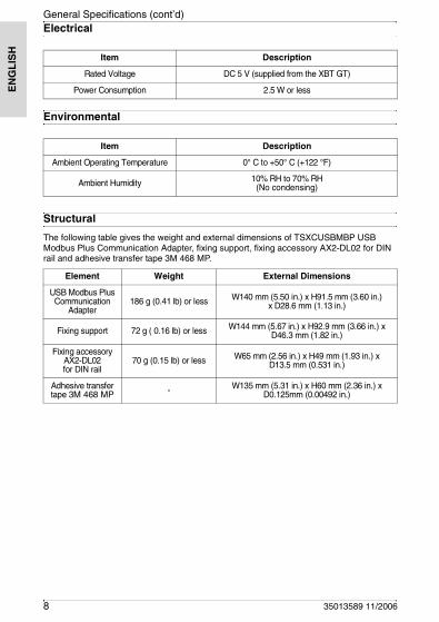
General Specifications (cont’d)Electrical
Environmental
Structural
The following table gives the weight and external dimensions of TSXCUSBMBP USB Modbus Plus Communication Adapter, fixing support, fixing accessory AX2-DL02 for DIN rail and adhesive transfer tape 3M 468 MP.
Item Description
Rated Voltage DC 5 V (supplied from the XBT GT)
Power Consumption 2.5 W or less
Item Description
Ambient Operating Temperature 0° C to +50° C (+122 °F)
Ambient Humidity 10% RH to 70% RH(No condensing)
Element Weight External Dimensions
USB Modbus Plus Communication
Adapter186 g (0.41 lb) or less W140 mm (5.50 in.) x H91.5 mm (3.60 in.)
x D28.6 mm (1.13 in.)
Fixing support 72 g ( 0.16 lb) or less W144 mm (5.67 in.) x H92.9 mm (3.66 in.) x D46.3 mm (1.82 in.)
Fixing accessory AX2-DL02 for DIN rail
70 g (0.15 lb) or less W65 mm (2.56 in.) x H49 mm (1.93 in.) x D13.5 mm (0.531 in.)
Adhesive transfer tape 3M 468 MP - W135 mm (5.31 in.) x H60 mm (2.36 in.) x
D0.125mm (0.00492 in.)

EN
GL
ISH
35013589 11/2006 9
Attachment methodsAttachment methods
Three different attachment methods can be used.
Screwing the fixing support to a wall or grid
Step 1: Place the fixing support on the wall or the grid in a vertical or horizontal direction. Use 4 attachment screws, the heads of which should be less than 6 mm (0.24 in) in height.
You can use the 4 screws supplied with the package:
Step 2: Insert the TSXCUSBMBP in the fixing support
Note: Please insert/remove the TSXCUSBMBP in/from the fixing support carrefully in the horizontal direction. Otherwise this may affect mechanical performance of the fixing support.
M0.16 x 0.24
6 pans wrench:mm
inch
6
0.24
0.12 on flats
3 on flats
M4 x 64 screws CBL ZS

EN
GL
ISH
10 35013589 11/2006
Attachment methods (cont’d)
Bonding the fixing support to a wall
Adhesive Application Recommendation:• The ideal application temperature is between 21 °C (69.8 °F) and 38 °C (100.4 °F).• Application on surfaces whose temperature is less than 10 °C (50 °F) is not
recommended because the adhesive would become too hard to enable adhesion.• For maximum bond strength the wall surface should be completely clean and dry.
Typical cleaning solvents are heptane (for oily surfaces) or isopropyl alcohol for plastics. Use reagent grade solvents since common household materials like rubbing alcohol frequently contain oils to minimize the drying affect on skin and can interfere with the performance of a pressure-sensitive adhesive. Carefully read and follow the manufacturer’s precautions and directions for use when working with solvents. These cleaning recommendations may not be in compliance with the rules of certain air quality management districts in California; consult applicable rules before use.
Step 1: Insert the TSXCUSBMBP in the fixing support.
Step 2: Bond the adhesive transfer tape 3M 468 MP included with the package contents to the fixing support. Apply pressure to enable the adhesive to come into direct contact with the surface.
Step 3: Remove the protective paper from the adhesive transfer tape 3M 468 MP.
Step 4: Bond the fixing support onto the wall in a vertical or horizontal direction.
For example, when placed horizontally:
Note: Please insert/remove the TSXCUSBMBP in/from the fixing support carrefully in the horizontal direction. Otherwise this may affect mechanical performance of the fixing support.
Adhesive transfer tape
3M 468 MP

EN
GL
ISH
35013589 11/2006 11
Attachment methods (cont’d)
Attaching the fixing support to DIN rail using the AX2-DL02
Step 1: Screw the fixing support to the fixing accessory AX2-DL02 for DIN rail in a vertical or horizontal direction. Use the 4 attachment screws and the 4 washers included with the package contents.
Step 2: Insert the TSXCUSBMBP in the fixing support.
Step 3: Place the fixing support with the TSXCUSBMBP onto the DIN rail as shown below. (Below example is for horizontal mount.)
Removing the TSXCUSBMBP and the AX2-DL02 from the DIN rail:
Note: Please insert/remove the TSXCUSBMBP in/from the fixing support carrefully in the horizontal direction. Otherwise this may affect mechanical performance of the fixing support.

EN
GL
ISH
12 35013589 11/2006
Connections9-pin sub-D Type (For Modbus Plus) and USB (For XBTGT)
Connect the TSXCUSBMBP to the Modbus Plus network using the 9-pin sub-D connector and to the XBT GT with the USB plug.
CAUTIONIMPROPER HANDLING HAZARD
Follow the procedure described below to prevent damage to the cable connector or the XBT GT.• When connecting the USB Data Transfer Cable to the PC or to the XBT
GT unit, insert the cable’s connector at the correct 90° angle.• When disconnecting the cable, make sure to hold the connector, not the
cable itself.
Failure to follow this instruction can result in injury or equipment damage.
USB port
Modbus Plus Network
Wire length including connector: 460 mm (18.1 in.)
9-pin sub-D connector

EN
GL
ISH
35013589 11/2006 13
This page is left blank intentionally.

EN
GL
ISH
14 35013589 11/2006