Embed Size (px)
Citation preview

May 4 , 2000 Slide 1Ottawa, ON May 23-25, 2000 XAUI /XGXS Proposal S l ide 1
IEEE 802.3ae
Task Force
XAUI/XGXS ProposalBy:
Don Alderrou, nSerial; Vipul Bhatt, Finisar; Brad Booth, Intel; Kirk Bovil, Blazel; Ed
Chang, NetWorth Technologies; Robert Dahlgren, SV Photonics; Kevin Daines, World Wide Packets; Joel Dedrick, AANetcom; Thomas Dineen, Dineen Consulting; Schelto
van Doorn, Infineon; Steve Dreyer, nSerial; Richard Dugan, Agilent; John Ewen, IBM;
Howard Frazier, Cisco; Mark Feuerstraeter, Intel; Eric Grann, Blaze; Steve Haddock, Extreme Networks; Chuck Haymes, IBM; Ken Herrity, Blaze; Jay Hoge, JDS Uniphase;
Osamu Ishida, NTT; Pat Kelly, Intel; Van Lewing, QED; David Lynch, Gennum; Jeff
Lynch, IBM; Henning Lysdal, Giga; Kreg Martin, Brocade Communications; Ron Miller, Brocade Communications; Shimon Muller, Sun; Bob Musk, JDS Uniphase; Brian
Peters, Blaze; Mark Ritter, IBM; Shawn Rogers, Texas Instruments; Koichiro Seto,
Hitachi Cable; Dave Simmons, Gennum; Jeff Stai, Qlogic; Daniel Svensson, SwitchCore; Steve Swanson, Corning; Rich Taborek, nSerial; Bharat Tailor, Gennum;
Jim Tavacoli, Accelerant Networks; Hemant Thakkar; Tom Truman, Bell Labs/Lucent;
Rick Walker, Agilent; Fred Weniger, Vitesse; Bill Wiedemann, Blaze; Jim Yokouchi, Sumitomo Electric; Jason Yorks, Cielo; Nariman Yousefi, Broadcom;

May 4 , 2000 Slide 2Ottawa, ON May 23-25, 2000 XAUI /XGXS Proposal S l ide 2
IEEE 802.3ae
Task Force
Presentation Purpose
§ Update of March ‘00 proposal
§ http://grouper.ieee.org/groups/802/3/ae/public/mar00/taborek_1_0300.pdf
§ Inclusion of 8B/10B Idle EMI Reduction proposal
§ http://grouper.ieee.org/groups/802/3/ae/public/may00/taborek_1_0500.pdf
§ Otherwise, no new material is introduced
§ Proposal is ready for Prime Time!

May 4 , 2000 Slide 3Ottawa, ON May 23-25, 2000 XAUI /XGXS Proposal S l ide 3
IEEE 802.3ae
Task Force
Description§ XAUI = 10 Gigabi t eX tended Attachment Unit Interface
§ X G X S = X G M I I eXtender Sublayer
§ C D R - based, 4 lane ser ial , sel f -t imed interface
§ 3.125 Gbaud , 8B/10B encoded over 20” FR-4 PCB t r aces
§ PHY and Protocol independent scalable archi tecture
§ Convenient implementat ion part i t ion
§ May be imp lemented i n CMOS, B i C M O S, S i G e
§ Direct mapping of RS/XGMII data to/from PCS
§ XGMII proposed by Howard Frazier, Cisco, et. al.http://grouper.i e e e .org/groups/802/3/10G_study/publ ic/ ju ly99/ f raz ie r_ 1 _ 0 7 9 9 . pd f

May 4 , 2000 Slide 4Ottawa, ON May 23-25, 2000 XAUI /XGXS Proposal S l ide 4
IEEE 802.3ae
Task Force
Applications
§ Increased XGMII reach
§ Low pin count interface = implementation flexibility
§ Ease link design with multiple jitter domains
§ Lower power consumption re: XGMII
§ Common transceiver module interface, enables SFF
§ P C S/PMA agent for WWDM
§ Avoids excessive penalt ies for a l l other P H Y s
§ Self-timed interface eliminates high-speed interface clocks

May 4 , 2000 Slide 5Ottawa, ON May 23-25, 2000 XAUI /XGXS Proposal S l ide 5
IEEE 802.3ae
Task Force
Highlights
§ Increased reach
§ XGMII is ~3” (~7 cm)
§ XAUI is ~20” (~50 cm)
§ Lower connection count
§ XGMII is 74 wires (2 sets of 32 data, 4 control & 1 clock)
§ XAUI is 16 wires (2 sets of 4 differential pairs)
§ Built -in jitter control
§ Chip -to-chip interconnect degrades XGMII source-synchronous clock
§ XAUI self -timed interface enables jitter attenuation at the receiver
May 4 , 2000 Slide 6Ottawa, ON May 23-25, 2000 XAUI /XGXS Proposal S l ide 6
IEEE 802.3ae
Task Force
Location - Layer Model
PHYSICAL
DATA LINK
NETWORK
TRANSPORT
SESSION
PRESENTATION
APPLICATION
OSIREFERENCE
MODELLAYERS
Reconciliation
MAC
MAC Control (Optional)
LLC
XAUI (Optional)
LANLAYERS
HIGHER LAYERS
MDI = Medium Dependent InterfaceXGMII = 10 Gigabit Media Independent InterfaceXAUI = 10 Gigabit Attachment Unit InterfacePCS = Physical Coding Sublayer
XGXS = XGMII Extender SublayerPMA = Physical Medium AttachmentPHY = Physical Layer DevicePMD = Physical Medium Dependent
PMD
MEDIUM
MDI
XGXS (Opt)
XGMII (Optional)
PMA
PCS
XGXS (Opt)

May 4 , 2000 Slide 7Ottawa, ON May 23-25, 2000 XAUI /XGXS Proposal S l ide 7
IEEE 802.3ae
Task Force
Implementation Example
TXC
TXD
R X C
R X D
PHY
MAC RS 36
36
XAUIXGMII
XGXS
MDI
X G X SPCS
PMA
PMD
“Big Chip” “LittleChip”
TransceiverForm Factor varies
from “daughter card”to small-form-factor
May 4 , 2000 Slide 8Ottawa, ON May 23-25, 2000 XAUI /XGXS Proposal S l ide 8
IEEE 802.3ae
Task Force
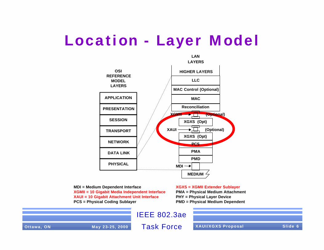
X G X S Funct ions§ Use 8B/10B transmission code
§ Perform column striping across 4 independent serial lanes
§ Identi f ied as lane 0, lane 1, lane 2, lane 3
§ Perform XAUI lane and interface (link) synchronization
§ Idle pattern adequate for link initialization
§ Perform lane-to-lane deskew
§ Perform clock tolerance compensation
§ Provide robust packet delimiters
§ Perform error control to prevent error propagation

May 4 , 2000 Slide 9Ottawa, ON May 23-25, 2000 XAUI /XGXS Proposal S l ide 9
IEEE 802.3ae
Task Force
Basic Code Groups
§ Similar to GbE
§ No even/odd al ignment, new Skip and Al ign
/A/ K28.3 (Align) - Lane deskew via code - group alignment
/K/ K28.5 (Sync) - Synchronization, EOP Padding
/R/ K28.0 (Skip) - Clock tolerance compensation
/S/ K27.7 (Start) - Start-of-Packet (SOP), Lane 0 ID
/T/ K29.7 (Terminate) - End-of- Packet (EOP)
/E/ K30.7 (Error) - Signaled upon detection of error
/d/ Dxx.y (data) - Packet data
May 4 , 2000 Slide 10Ottawa, ON May 23-25, 2000 XAUI /XGXS Proposal S l ide 10
IEEE 802.3ae
Task Force
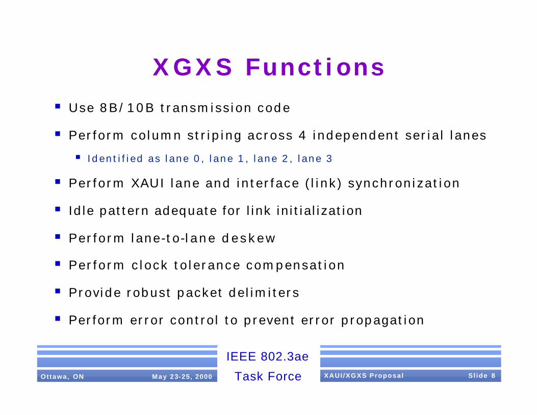
“Extra” Code Groups
§ The following are included in related proposals:
/Kb/ K28.1 (Busy Sync) - Synchronization/Rate control
/Rb/ K23.7 (Busy Skip) - Clock tolerance comp/Rate control
/LS/ K28.1 (Link Signaling) - LSS proposal
§ The following remaining 8B/10B special code- groups are not used:
K28.21, K28.4, K28.6, K28.7
1 R e s e r v e d f o r F i b r e C h a n n e l u s a g e i n N C I T S T 1 1 1 0 G F C p r o j e c t p r o p o s a l s

May 4 , 2000 Slide 11Ottawa, ON May 23-25, 2000 XAUI /XGXS Proposal S l ide 11
IEEE 802.3ae
Task Force
Data Mapping: MAC to XGMII
D7 D6 D5 D4 D3 D2 D1 D0
MAC’s Serial Bit Stream First Bit
D7 D6 D5 D4 D3 D2 D1 D0
MAC’s Serial Bit Stream First Bit
TXDn<0>
XGMII Data Bundles
RXDn<0>
TXDn<1>
RXDn<1>
TXDn<2>
RXDn<2>
TXDn<3>
RXDn<3>
TXDn<4>
RXDn<4>
TXDn<5>
RXDn<5>
TXDn<6>
RXDn<6>
TXDn<7>
RXDn<7>
LSBMSB
TXDn<K>
RXDn<K>
MAC is a bit serial interface
MAC octets represented by D7:0 map to 4 consecutive XGMII Data Bundles in rotating fashion of n=0:3 XGMII is a 32 bit data + 4 control bit interface

May 4 , 2000 Slide 12Ottawa, ON May 23-25, 2000 XAUI /XGXS Proposal S l ide 12
IEEE 802.3ae
Task Force
Data Mapping: XGMII to XAUI
8B/10BEncoder
TXDn<7:0,K>
(1.25 billion octets/s)
XGXS Service Interface
(1.25 billion code-groups/s)
8B/10BDecoder
XGXS Service Interface
(1.25 billion code-groups/s)
0 1 2 34 5 6 7 8 90 1 2 345 6 7 8 9
XGXS DECODE functionXGXS ENCODE function
7 6 5 4 3 2 1 0
Output of ENCODE function Input to DECODE function
10
8 + control 8 + control
10
0 0 1 1 1 1 1 x x x Properly aligned comma+ symbol
XAUIn<9:0>XAUIn<9:0>
a b c d e i f g h j a b c d e i f g h j
Input to ENCODE function Output of DECODE functionH G F E D C B A K H G F E D C B A K
XAUI(12.5 billion rx_bits/s)
bit 0 is received first
XAUI(12.5 billion tx_bits/s)
bit 0 is transmitted first
XGMII(1.25 billion octets/s)XGMII
K
RXDn<7:0,K>
7 6 5 4 3 2 1 0 K

May 4 , 2000 Slide 13Ottawa, ON May 23-25, 2000 XAUI /XGXS Proposal S l ide 13
IEEE 802.3ae
Task Force
Data Mapping Example
Lane 0 K R S dp d d --- d d d df A K R K
Lane 1 K R dp dp d d --- d d df T A K R K
Lane 2 K R dp dp d d --- d d df K A K R K
Lane 3 K R dp ds d d --- d d df K A K R K
XGXS Encoded Da ta
R S/XGMII
D<7:0,K0> I I S dp d d --- d d d df I I I I
D<15:8,K1> I I dp dp d d --- d d df T I I I I
D<23:16,K2> I I dp dp d d --- d d df I I I I I
D<31:24,K3> I I dp ds d d --- d d df I I I I I

May 4 , 2000 Slide 14Ottawa, ON May 23-25, 2000 XAUI /XGXS Proposal S l ide 14
IEEE 802.3ae
Task Force
Idle Encoding
§ Idle (no data to send) is conveyed by the randomized pattern /A/ K/R/:
+T-A+K-R-K+R+R+K-K+ R+K-R-K+R+R+R+K (example pattern)
-K+R+R+K-R-R-K+ R+K-R-R-K+ R+K-K+ R+A … on each XAUI l ane
§ /A/ spacing is randomized: 16 min, 32 max (80-bit d e s k e w capability)
§ /K/R/s between /A/s randomly selected (no discrete spectrum)
See ht tp ://grouper .i e e e .org/groups/802/3/ a e/publ ic/may00/t a b o r e k _ 1 _ 0 5 0 0 . pd f fo r add i t iona l de ta i l s
§ /A/, /K/ and /R/ are all a hamming distance of 3 from each other
§ Minimum IPG pattern is /A/K/R/ sequence, in order

May 4 , 2000 Slide 15Ottawa, ON May 23-25, 2000 XAUI /XGXS Proposal S l ide 15
IEEE 802.3ae
Task Force
Synchronizat ion§ X A U I 4 -lane l ink synchronizat ion is a 2 step process
1. Acquire sync on all 4 lanes individually;
2. Align/deskew synchronized lanes.
§ Loss - of - Sync on any lane resu l ts in XAUI l ink Loss- of - Sync
§ Lane sync acquis i t ion s imi lar to 1000BASE- X P C S
§ U s e hysteresis to preclude false sync and Loss-of- Sync due to bit errors
§ R e -synchronize only upon Loss-of- Sync (i.e. no “hot-sync”)
§ Periodic Align (/A/-column) check a good link health check
§ XAUI l ink sync is fast, straightforward and rel iable
§ See backup sl ides for an i l lustration

May 4 , 2000 Slide 16Ottawa, ON May 23-25, 2000 XAUI /XGXS Proposal S l ide 16
IEEE 802.3ae
Task Force
Deskew§ Skew is imparted by act ive and pass ive l ink e lements
§ X G X S d e s k e w accounts for a l l skew present at the Rx
§ L a n e d e s k e w performed by al ignment to d e s k e w pattern present in
Idle/IPG stream: Align /A/ code- groups in a l l lanes
§ 40 UI d e s k e w pattern needs to be 80 bits
§ /A/ column Idle/IPG spacing is 16 columns (160 bits) minimum
Skew Source # Skew Total Skew
SerDes Tx 1 1 UI 1 UI
PCB 2 1 UI 2 UI
Medium 1 <16 UI <16 UI
SerDes Rx 1 20 UI 20 UI
Total <39 UI

May 4 , 2000 Slide 17Ottawa, ON May 23-25, 2000 XAUI /XGXS Proposal S l ide 17
IEEE 802.3ae
Task Force
X G X S Deskew
Lane 3 K K R A K R R K K R K R
Lane 0 K K R A K R R K K R K R
Lane 1 K K R A K R R K K R K R
Lane 2 K K R A K R R K K R K R
Skewed data at receiver input. Skew ~18 bits
Lane 1 K K R A K R R K K R K R
Lane 2 K K R A K R R K K R K R
Lane 3 K K R A K R R K K R K R
Lane 0 K K R A K R R K K R K R
D e s k e w lanes by lining up Align code-groups

May 4 , 2000 Slide 18Ottawa, ON May 23-25, 2000 XAUI /XGXS Proposal S l ide 18
IEEE 802.3ae
Task Force
Clock Tolerance Compensation
§ The XGXS must restore the temporal f idel i ty of the s ignal by:
a. Repeating by amplifying and/or reshaping the signal w/<100% jitt er transfer;
b. Retiming the data to a timing reference other than the received data.
§ Idle pattern Skip (/R/) columns may be inserted/removed to adjust
for clock tolerance dif ferences due to ret iming on ly
§ Skip columns may be inserted anywhere in Idle stream
§ Proper disparity Skip required in each lane
§ Any Skip column may be removed
§ Clock to lerance for 1518 byte packet @ ±100 ppm is 0.76 UI/lane
§ A few bytes of elasticity buffering is sufficient to wait for many (~13) frames in case a Skip column is not available for removal.

May 4 , 2000 Slide 20Ottawa, ON May 23-25, 2000 XAUI /XGXS Proposal S l ide 19
IEEE 802.3ae
Task Force
Skip Column Insert Example
Lane 0 K R S dp d d --- d d d df A K R K
Lane 1 K R dp dp d d --- d d df T A K R K
Lane 2 K R dp dp d d --- d d df K A K R K
Lane 3 K R dp ds d d --- d d df K A K R K
Lane 0 K R S dp d d --- d d d df A R K R
Lane 1 K R dp dp d d --- d d df T A R K R
Lane 2 K R dp dp d d --- d d df K A R K R
Lane 3 K R dp ds d d --- d d df K A R K R
Skip column inserted here

May 4 , 2000 Slide 21Ottawa, ON May 23-25, 2000 XAUI /XGXS Proposal S l ide 20
IEEE 802.3ae
Task Force
Error Control
§ Packets with detected errors must be aborted
§ 8B/10B code v iolat ion detect ion may be propagated forward
§ IPG spec ia l code groups are chosen to ensure that running
disparity errors are detected
§ Rule: Signal Error code upon detected error or in column containing EOP if the error is detected in the column
fol lowing the EOP.
§ Error is s ignaled per lane s ince dispar i ty is checked per lane
§ XGXS checks received packets for proper formation

May 4 , 2000 Slide 22Ottawa, ON May 23-25, 2000 XAUI /XGXS Proposal S l ide 21
IEEE 802.3ae
Task Force
Electrical
§ Electrical interface is based on low swing AC coupled differential interface
§ AC coupling is required at receiver inputs
§ Link compliance point is at the receiver
§ Transmitter may use equalization as long as receiver
specif ications are not exceeded

May 4 , 2000 Slide 23Ottawa, ON May 23-25, 2000 XAUI /XGXS Proposal S l ide 22
IEEE 802.3ae
Task Force
XAUI Rx/Tx & Interconnect
Transmitter Parameter Value
Vo Dif(max) 800 mV
Vo Dif(min) 500 mV
Voh AC
Vol AC
Iout nominal 6.5 mA
Differential Skew(max) 15 ps
Receiver Parameter Value
Vin Dif(max) 1000 mV
Vin Dif(min) 175 mV
Loss 50ΩΩ 9.1 dB
Differential Skew(max) 75 ps
Interconnect Parameter Value
Tr/Tf Min, 20%-80% 60 ps1
Tr/Tf Max, 20%-80% 131 ps1
PCB Impedance 100 ±10ΩΩ
Connector Impedance 100 ±30ΩΩ
Source Impedance 100 ±20ΩΩ
Load Termination 100 ±20ΩΩ
Return Loss 10 dB2
1. Optional if transmitter meets the receiver
jitter and eye mask with golden PCB
2. SerDes inputs must meet the return loss from 100 MHz to 2.5 GHz (0.8 x 3.125Gbaud)

May 4 , 2000 Slide 24Ottawa, ON May 23-25, 2000 XAUI /XGXS Proposal S l ide 23
IEEE 802.3ae
Task Force
XAUI Loss Budget
Item Loss
Connector Loss 1 dB
NEXT + FEXT Loss 0.75 dB
PCB Loss 7.35 dB
Loss Budget 9.1 dB
PCB Condition Normal Worst
MSTL Loss Max (dB/in) 0.32 0.43
Max Distance (in) 23” 17.1”
PCB Condition Normal Worst
STL Loss Max (dB/in) 0.41 0.55
Max Distance (in) 18” 13.4”
Normal PCB was assumed with loss tangent of 0.22. Worst case it was assumed high temperature and humidity 85/85.
Better FR4 grade may reduce loss by as much as 50%.
HP test measurement for 20" line showed 5.2 dB loss or 0.26dB/ in based on the eye loss, the loss assumed here is very conservative.

May 4 , 2000 Slide 25Ottawa, ON May 23-25, 2000 XAUI /XGXS Proposal S l ide 24
IEEE 802.3ae
Task Force
XAUI Jitter
Jitter Compliance Point Tx1 Rx
Deterministic Jitter 0.17 UI 0.41 UI Total Jitter 0.35 UI2 0.65 UI 1-sigma RJ @ max DJ for 10-12 BER3 4.11 ps 5.49 ps 1-sigma RJ @ max DJ for 10-13 BER3 3.92 ps 5.23 ps
1. Tx point is for reference. Rx point is for compliance.
2. The SerDes component should have better jitter performance than specified here to allow for system noise.
3. 1-Sigma value listed here are at maximum DJ, if the DJ value is smaller then the 1-Sigma RJ may increase to the total jitter value.

May 4 , 2000 Slide 26Ottawa, ON May 23-25, 2000 XAUI /XGXS Proposal S l ide 25
IEEE 802.3ae
Task Force
Summary
§ Meets HSSG Object ives and PAR 5 Criter ia
§ Provides PHY, Protocol & Application independence
§ Based on generic 10 Gbps chip-to-chip interconnect
§ Resembles simple and famil iar 1000BASE- X P H Y
§ Low Complexity, Low Latency, Quick Synchronizing
§ May be integrated into MAC/RS ASIC, el iminating XGMII

May 4 , 2000 Slide 26Ottawa, ON May 23-25, 2000 XAUI /XGXS Proposal S l ide 26
IEEE 802.3ae
Task Force
Backup Slides
§ XGXS Synchronization state diagrams

Comma_Detect_2
Loss_of_Sync
Sync_Status <= FAILEnable_CDET <= TRUE
cg_bad
Comma_Detect_3
Comma_Detect_1
Enable_CDET <= FALSE
Reset
Sync_Complete
cg_comma
Sync_Acq’d_1
Sync_Status <= OK
Sync_Acq’d_2A
Gd_cg <= Gd_cg + 1 cg_good * Gd_cg != 3
Sync_Acq’d_2
Gd_cg <= 0
Sync_Acq’d_3
Gd_cg <= 0
Sync_Acq’d_4
Gd_cg <= 0
Sync_Acq’d_3A
Gd_cg <= Gd_cg + 1 * Gd_cg != 3cg_good
Sync_Acq’d_4A
Gd_cg <= Gd_cg + 1 * Gd_cg != 3cg_good
* Gd_cg = 3cg_good
* Gd_cg = 3cg_good
* Gd_cg = 3cg_good
cg_bad
cg_bad
cg_comma
cg_comma
cg_good
cg_bad
cg_bad
cg_bad
cg_bad
cg_bad
cg_bad
cg_good
cg_good
cg_bad
Note1: cg_bad may haveprogrammable count todisable back-2-back errors
Note2: cg_bad may bedisabled when Enable_DSkewis TRUE and in Sync_Acq’d_1
Note3: no_comma containsprogrammable timer to count time between comma code groups
Sync_Acq’d_1A
Sync_Status <= OK_NOC
cg_commacg_bad
no_comma

Skew_Detect_2
Loss_of_Skew
Skew_Status <= FAIL Enable_DSkew <= TRUE
Deskew_Error
Skew_Detect_3
Skew_Detect_1
Enable_DSkew <= FALSE
Reset + Any Sync_Status = FAIL
DeSkew_Complete
Column_Of_A
Skew_Acq’d
Skew_Status <= OK
Deskew_Error
Deskew_Error
Column_Of_A
Column_Of_A


![Clause 52 Optical PMD Test Suite - UNH InterOperability Laboratory · 2014. 4. 16. · [2] IEEE Std. 802.3ae-2002, subclause 52.6.1, Table 52-12 (10GBASE-LR/LW) InterOperability Laboratory](https://img.dokumen.tips/doc/110x75/610d43011dcaf703ce4e27d0/clause-52-optical-pmd-test-suite-unh-interoperability-laboratory-2014-4-16.jpg)

![TG3-Criteria-Definitions - IEEEgrouper.ieee.org/.../May00/00110r9P802-15_TG3-Criteria-Definition… · Web viewTG3-Criteria-Definitions. Date Submitted [11 May, 2000] Source [Mary](https://img.dokumen.tips/doc/110x75/5e47c7b64f1bc03a2755e404/tg3-criteria-definitions-web-view-tg3-criteria-definitions-date-submitted-11.jpg)