Embed Size (px)
Citation preview

Broadcast-Quality Up/Cross/Downconverter
Installation and Operation Manual
Edition B175-100159-00


Edition B December 2009
X50Broadcast-Quality Up/Cross/Downconverter
Installation and Operation Manual

Copyright InformationCopyright © 2009 Harris Corporation, 1025 West NASA Boulevard, Melbourne, Florida 32919-0001 U.S.A. All rights reserved. This publication supersedes all previous releases. Printed in Canada.
This product and related documentation are protected by copyright and are distributed under licenses restricting their use, copying, distribution, and decompilation. No part of this product or related documentation may be reproduced in any form by any means without prior written authorization of Harris Corporation and its licensors, if any.
This publication could include technical inaccuracies or typographical errors. Changes are periodically added to the information herein; these changes will be incorporated into new editions of the publication. Harris Corporation may make improvements and/or changes in the product(s) and/or the program(s) described in this publication at any time.
TASCAM® is a registered trademark of TEAC Corporation. Dolby® is a registered trademark of Dolby laboratories.
Warranty InformationThe limited warranty policy provides a complete description of your warranty coverage, limitations, and exclusions, as well as procedures for obtaining warranty service. To view the complete warranty, visit our website.This publication is provided “as is” without warranty of any kind, either express or implied, including, but not limited to, the implied warranties of merchantability, fitness for a particular purpose, or non-infringement.

X50 Installation and Operation Manual iiiCopyright © 2009, Harris Corporation
Contents
PrefaceManual Information ............................................................................................... vii
Purpose ........................................................................................................... viiAudience ......................................................................................................... viiRevision History ............................................................................................. viiWriting Conventions .....................................................................................viiiObtaining Documents ....................................................................................viii
Unpacking/Shipping Information ........................................................................... ixUnpacking a Product ....................................................................................... ixProduct Servicing ............................................................................................ ixReturning a Product ......................................................................................... ixRestriction on Hazardous Substances (RoHS) Directive ................................. xWaste from Electrical and Electronic Equipment (WEEE) Directive ........................................................................................... xi
Safety ..................................................................................................................... xiiSafety Terms and Symbols in this Manual ..................................................... xii
Chapter 1: IntroductionProduct Features ...................................................................................................... 1
Inputs ................................................................................................................ 1Outputs ............................................................................................................. 2Video Processing .............................................................................................. 2ANC Processing ............................................................................................... 2Audio Processing .............................................................................................. 3Other ................................................................................................................. 3
Options .................................................................................................................... 3Front and Back Views ............................................................................................. 4
Pinouts .............................................................................................................. 4Packing List ............................................................................................................. 5Signal Flow .............................................................................................................. 6
Chapter 2: InstallationPreparing for Installation ......................................................................................... 7
Electrical Requirements ................................................................................... 7Environmental Requirements ........................................................................... 7
Rack Mounting ........................................................................................................ 8Jumpers .................................................................................................................. 10Selecting an External Balun .................................................................................. 12
iv X50 Installation and Operation ManualCopyright © 2009, Harris Corporation
Contents
Configuring Network Settings ............................................................................... 13Supported Network Protocols ........................................................................ 13Making Required Hardware Connections ...................................................... 13Setting IP and Subnet Mask Addresses .......................................................... 13
Changing the PC Network Settings ....................................................................... 16Remote Control of the X50 ................................................................................... 18
Preparing for Remote Control via Control Panel ........................................... 19Selecting a Remote Unit to Control ............................................................... 19Configuring for Web Browser Control .......................................................... 21Configuring SNMP Support ........................................................................... 22Configuring Third-Party SNMP Software Control ........................................ 25
Monitoring and Control Using MIBs .................................................................... 27
Chapter 3: ControlsOverview ............................................................................................................... 29Front Panel Controls .............................................................................................. 29
Pushbuttons .................................................................................................... 30LEDs ............................................................................................................... 30Main Menu Items ........................................................................................... 31
Advanced Controls ................................................................................................ 31Aspect Ratio Conversion ....................................................................................... 33
Custom ARC .................................................................................................. 33Automatic ARC .............................................................................................. 33Output AFD, VI and WSS .............................................................................. 38
Closed Captioning and DVB Teletext Captioning ................................................ 43Color Correction .................................................................................................... 43
White Slope and Black Stretch ....................................................................... 43Gamma Correction ......................................................................................... 45
Custom Splash Screen ........................................................................................... 46Limitations on the Secondary Channel .................................................................. 46Auto Route Feature ................................................................................................ 46Proc Bypass ........................................................................................................... 47Audio Processing ................................................................................................... 47Audio Metadata ..................................................................................................... 48
Chapter 4: SpecificationsConversion Capabilities ........................................................................................ 51Video Input ............................................................................................................ 52
3G/HD/SD-SDI .............................................................................................. 52Fiber (OP+SFP+TR13P Module) ................................................................... 52S-Video ........................................................................................................... 53Composite Video ............................................................................................ 53Component Video .......................................................................................... 53Genlock .......................................................................................................... 54
Video Output ......................................................................................................... 553G/HD/SD-SDI .............................................................................................. 55Fiber (OP+SFP+TR13P Module) ................................................................... 56HDMI ............................................................................................................. 56S-Video ........................................................................................................... 57

X50 Installation and Operation Manual vCopyright © 2009, Harris Corporation
Contents
Composite Video ............................................................................................ 57Component Video .......................................................................................... 58
Audio Input ............................................................................................................ 59AES/DARS ..................................................................................................... 59Analog ............................................................................................................ 59
Audio Output ......................................................................................................... 60AES ................................................................................................................ 60Analog ............................................................................................................ 60
Communications .................................................................................................... 61GPI In/Out ...................................................................................................... 61RS-422 ............................................................................................................ 61LAN ................................................................................................................ 61Temperature ................................................................................................... 61Power Consumption ....................................................................................... 61Dimensions and Weight ................................................................................. 62
Appendix A: Laser Safety GuidelinesLaser Safety ........................................................................................................... 63
Precautions for Enclosed Systems .................................................................. 63Precautions for Unenclosed Systems ............................................................. 64
Label ...................................................................................................................... 64
Appendix B: Audio Bit ManipulationOverview ............................................................................................................... 65Channel Status Bits ............................................................................................... 66Validity and User Bits ........................................................................................... 67Miscellaneous Data ............................................................................................... 68
IndexKeywords ....................................................................................................... 69

vi X50 Installation and Operation ManualCopyright © 2009, Harris Corporation
Contents

X50 Installation and Operation Manual viiCopyright © 2009, Harris Corporation
Preface
Manual Information
PurposeThis manual details the features, installation, operation, maintenance, and specifications for the X50 Up/Cross/Downconverter.
AudienceThis manual is written for engineers, technicians, and operators responsible for the installation, setup, and/or operation of X50 Up/Cross/Downconverter.
Revision History
Table P-1. Document Revision History
Edition Date Revision HistoryA November 2009 Initial Release
B December 2009 New specifications added

viii X50 Installation and Operation ManualCopyright © 2009, Harris Corporation
Preface
Writing ConventionsTo enhance your understanding, the authors of this manual have adhered to the following text conventions:
Obtaining DocumentsProduct support documents can be viewed or downloaded from our website. Alternatively, contact your Customer Service representative to request a document.
Table P-1. Writing Conventions
Term or Convention Description
Bold Indicates dialog boxes, property sheets, fields, buttons, check boxes, list boxes, combo boxes, menus, submenus, windows, lists, and selection names
Italics Indicates E-mail addresses, the names of books or publications, and the first instances of new terms and specialized words that need emphasis
CAPS Indicates a specific key on the keyboard, such as ENTER, TAB, CTRL, ALT, or DELETE
Code Indicates variables or command-line entries, such as a DOS entry or something you type into a field
> Indicates the direction of navigation through a hierarchy of menus and windows
hyperlink Indicates a jump to another location within the electronic document or elsewhere
Internet address Indicates a jump to a website or URL
NoteIndicates important information that helps to avoid and troubleshoot problems

X50 Installation and Operation Manual ixCopyright © 2009, Harris Corporation
Preface
Unpacking/Shipping InformationUnpacking a Product
This product was carefully inspected, tested, and calibrated before shipment to ensure years of stable and trouble-free service. 1. Check equipment for any visible damage that may have occurred during
transit. 2. Confirm that you have received all items listed on the packing list. 3. Contact your dealer if any item on the packing list is missing.4. Contact the carrier if any item is damaged.5. Remove all packaging material from the product and its associated
components before you install the unit.Keep at least one set of original packaging, in the event that you need to return a product for servicing.
Product ServicingExcept for firmware upgrades and jumper selections, the X50 is not designed for field servicing. Return the X50 unit to the Harris Customer Service Center for all hardware upgrades, modifications, or repairs.
Returning a ProductIn the unlikely event that your product fails to operate properly, contact Customer Service to obtain a Return Authorization (RA) number, and then send the unit back for servicing. If the original package is not available, you can supply your own packaging as long as it meets the following criteria:• The packaging must be able to withstand the product’s weight.• The product must be held rigid within the packaging.• There must be at least 2 in. (5 cm) of space between the product and the
container.• The corners of the product must be protected.Ship products back to us for servicing prepaid and, if possible, in the original packaging material. If the product is still within the warranty period, we will return the product prepaid after servicing.

x X50 Installation and Operation ManualCopyright © 2009, Harris Corporation
Preface
Restriction on Hazardous Substances (RoHS) DirectiveDirective 2002 / 95 / EC—commonly known as the European Union (EU) Restriction on Hazardous Substances (RoHS)—sets limits on the use of certain substances found in electrical and electronic equipment. The intent of this legislation is to reduce the amount of hazardous chemicals that may leach out of landfill sites or otherwise contaminate the environment during end-of-life recycling. The Directive, which took effect on July 1, 2006, refers to the following hazardous substances: • Lead (Pb)• Mercury (Hg)• Cadmium (Cd)• Hexavalent Chromium (Cr-V1)• Polybrominated Biphenyls (PBB)• Polybrominated Diphenyl Ethers (PBDE)In accordance with this EU Directive, products sold in the European Union will be fully RoHS-compliant and “lead-free.” Spare parts supplied for the repair and upgrade of equipment sold before July 1, 2006 are exempt from the legislation. Equipment that complies with the EU directive will be marked with a RoHS-compliant symbol, as shown in Figure P-1.
Figure P-1. RoHS Compliance Symbol

X50 Installation and Operation Manual xiCopyright © 2009, Harris Corporation
Preface
Waste from Electrical and Electronic Equipment (WEEE) Directive
The European Union (EU) Directive 2002 / 96 / EC on Waste from Electrical and Electronic Equipment (WEEE) deals with the collection, treatment, recovery, and recycling of electrical and electronic waste products. The objective of the WEEE Directive is to assign the responsibility for the disposal of associated hazardous waste to either the producers or users of these products. As of August 13, 2005, producers or users are required to recycle electrical and electronic equipment at end of its useful life, and must not dispose of the equipment in landfills or by using other unapproved methods. (Some EU member states may have different deadlines.)In accordance with this EU Directive, companies selling electric or electronic devices in the EU will affix labels indicating that such products must be properly recycled. Contact your local Sales representative for information on returning these products for recycling. Equipment that complies with the EU directive will be marked with a WEEE-compliant symbol, as shown in Figure P-2.
Figure P-2. WEEE Compliance Symbol

xii X50 Installation and Operation ManualCopyright © 2009, Harris Corporation
Preface
SafetyCarefully review all safety precautions to avoid injury and prevent damage to this product or any products connected to it. If this product is rack-mountable, it should be mounted in an appropriate rack using the rack-mounting positions and rear support guides provided. To protect a frame from circuit overloading, connect each frame to a separate electrical circuit. If this product relies on forced air cooling, all obstructions to the air flow should be removed prior to mounting the frame in the rack. If this product has a provision for external earth grounding, ground the frame to the earth using the protective earth ground on the rear panel.IMPORTANT! Only qualified personnel should perform service procedures. Always disconnect the power supply before removing the lid.
Safety Terms and Symbols in this ManualWARNINGStatements identifying conditions or practices that may result in personal injury or loss of life. High voltage is present.
CAUTIONStatements identifying conditions or practices that can result in damage to the equipment or other property.

X50 Installation and Operation Manual 1Copyright © 2009, Harris Corporation
Chapter 1
Introduction
Product FeaturesThe X50 is a standalone up/down/cross converter in a 1-RU format. The X50 can provide broadcast quality multi-standard conversion along with support for aspect ratio change and AFD processing, closed captioning processing, video processing amplifier and video frame synchronization and delay, with built-in color correction. Audio processing capabilities include handling of 16 channels of embedded audio and 8 channels of discrete audio via AES or analog interfaces, with audio synchronization and delay for audio-to-video tracking.Full handling of the embedded audio metadata is provided with ability to de-embed and re-embed metadata from external sources. An optional fiber optic transceiver sub-module (SFP) will allow one receiver and one transmitter to be added to complement the SDI electrical inputs and outputs.
Inputs• Two auto-sensing SD/HD/3G SDI inputs and one SD/HD/3G SDI fiber
input with embedded audio, VANC data (WSS/VI/AFD, audio metadata and closed captioning/teletext data)
• One SD/HD component YPrPb/RGB input• One SD composite input• One S-Video input• Error monitoring (EDH, CRC) on each SDI input• Genlock input with loopback: analog composite with support for tri- and
bi-level sync • DARS input, unbalanced• Four AES inputs, unbalanced• Eight-channel analog audio inputs, balanced• RS-422 serial port for external metadata• Four GPI inputs, TTL

2 X50 Installation and Operation ManualCopyright © 2009, Harris Corporation
Chapter 1: Introduction
Outputs• Two SD/HD/3G SDI outputs and one SD/HD/3G SDI fiber output carrying
the converted program signal with embedded audio, VANC data (WSS/VI/AFD, audio metadata and closed captioning/teletext data)
• One SD/HD component YPrPb/RGB output• One SD composite output• One S-Video output• One HDMI output (audio and video streams)• User-selectable input and output video standard/formats• Four AES outputs, unbalanced• Eight-channel analog audio outputs, balanced• RS-422 serial port for external metadata• Four GPIO outputs, TTL
Video Processing• Dual-output processor supporting simultaneous down- and cross
conversion; simultaneous up- and ARC conversion• Advanced 10-bit image processor• Motion adaptive de-interlacing for exceptional vertical resolution• Color space conversion between SD (601) and HD (709)• User-configurable picture-resizing aspect ratio conversion (H/V size, H/V
position and cropping)• Fixed preset aspect ratios that include 16:9 anamorphic, 16:9 middle cut,
14:9, 4:3 and pixel true• Variable ARC controls• Aspect ratio adjustment according to embedded WSS/VI/AFD information• User-selectable color for the internally-generated background, 1…8 colors • Support for up to twelve frames of delay through the entire video path• Clean cut transition during aspect ratio change• SDI video clipping• Video noise reduction and detail enhancement• Video proc amp controls• Color correction
ANC Processing• Trans-coding of CC or TT according to input and output video formats• WSS, VI, and AFD processing: detection, insertion or re-insertion

X50 Installation and Operation Manual 3Copyright © 2009, Harris Corporation
Chapter 1: Introduction
Audio Processing• Embedded audio processing (de-embed, delay/sync, sample rate
conversion, embed) for sixteen channels (four groups)• Discrete audio processing for eight channels (four AES pairs or eight analog
mono channels)• Audio proc amp controls (gain, phase invert)• Handling of any embedded compressed audio with fixed delay• 24-bit audio processing; word-length control on embedded and AES outputs• Support for compressed and linear PCM in the same audio group• Audio delay that matches video propagation plus additional user delay of up
to 2.5 seconds
Other• 10/100 Ethernet connectivity• Store-and-recall AFD presets through CCS-P and SNMP• User-selectable LOV modes: Pass, Freeze, Black, and Test Pattern• Built-in SD/HD/3G test generator containing cross hatch pattern, color bar
signal, black, white, and horizontal sweep with chroma or luma-only signals• Clean handling of hot switch on input• Front panel and CCS Pilot control accessibility• Store-and-recall of control parameters via CCS applications and control
panels• Future support for SD memory card for logo/trouble slide storage and
firmware upgrades
Options
See page 12 for suggested AES baluns.Harris recommends the OREMTOOL for removing 1.0/2.3 FPB connectors on the X50. This product is available from White Sands Engineering. See page 5 in the following document:http://www.whitesandsengineering.com/downloads/catalog.pdf
Table 1-1. X50 Orderable Options
Name DescriptionX50OPT-3G 3.0 Gb/s input and output option for X50
OP+SFP+TR13P Small Form Factor Pluggable (SFP) for Harris fiber optic modules: 1310 nm wavelength transceiver with pathological support for baseband video
X50OPTCAB-AES BNC-to-DIN 1.0/2.3 AES interface cable

4 X50 Installation and Operation ManualCopyright © 2009, Harris Corporation
Chapter 1: Introduction
Front and Back Views
Figure 1-1. Front and Back Views
Pinouts
Figure 1-2. Female Back Panel Data Pinouts
Figure 1-3. Female Back Panel GPI Pinouts
15 234
9 678
G Tx-Rx+
Tx+Rx-
Ground
15 234
9 678
In1
Ground
In2GIn4 In3
Out4 Out3 Out2 Out1

X50 Installation and Operation Manual 5Copyright © 2009, Harris Corporation
Chapter 1: Introduction
Figure 1-4. Female Back Panel Analog Audio Input and Output Pinouts
Packing List• X50 frame with two power supplies• AC Power cords (2). • X50 Documentation CD-ROM package.
1213 510 7811 412 9 6 3
1425 1722 192023 1624 21 18 15
- ---G GGG+ +++Ch1a Ch4aCh3aCh2a Ch3bCh2bCh1b Ch4b
GGGG ++++--- -

6 X50 Installation and Operation ManualCopyright © 2009, Harris Corporation
Chapter 1: Introduction
Signal Flow
Figure 1-5. X50 Signal Flow
SD
I 2 in
(S
D/H
D/3
G S
DI w
ith
embe
dded
aud
io)
SD
I 1 in
(S
D/H
D/3
G S
DI w
ith
embe
dded
aud
io)
Fibe
r in
(SD
/HD
/3G
SD
I with
em
bedd
ed a
udio
)
Bala
nced
Rx
Bal
ance
d an
alog
in
(8-c
hann
el a
udio
)8-
ch
De-
inte
rlace
r
Scal
ar 1
Ana
log
Vid
eo
Enco
der
Dig
ital t
o an
alog
HD
MI
Tx
AE
SR
x
Fram
e sy
ncS
cala
r 2
SR
C
#
Com
pone
nt o
ut
S-V
ideo
out
HD
MI o
ut
24-c
h
16-c
h
8-ch
8-ch
8-ch
8-ch
Com
posi
te o
ut
SD
I 1
SD
I 2
CP
U m
onito
ring
and
cont
rol
4 AE
S in
(8
-cha
nnel
aud
io)
Ana
log
vide
o de
code
r
Com
pone
nt in
S-Vi
deo
in
Com
posi
te in
Aud
io s
ync
an
d de
lay
SFP
Tx
Fibe
r out
(SD
/HD
/3G
SD
I w
ith e
mbe
dded
aud
io)
DA
RS
inA
ES Rx
Vid
eo ti
min
g
Aud
io ti
min
g
Aud
io
genl
ock
and
vide
o tim
ing
Ref
eren
ce
in lo
op
Vid
eoP
roc
mux
and
vi
deo
TSG
Aud
io/A
NC
mux
and
vi
deo
TSG
Aud
io/A
NC
Byp
ass
SD
I 2 o
ut (S
D/H
D/3
G S
DI
with
em
bedd
ed a
udio
)
Aud
iode
mux
16-c
h
16-c
h
AN
Cde
mux
AN
C
proc
Aud
ioTo
ne
Gen
Aud
io
rout
ing
and
proc
6-ch
16-c
h
AE
STx
DA
CBa
lanc
edTx
4 A
ES
out
(8-c
hann
el a
udio
)
8-ch
8-ch
Bal
ance
d an
alog
out
(8
-cha
nnel
aud
io)
#
8-ch

X50 Installation and Operation Manual 7Copyright © 2009, Harris Corporation
Chapter 2
Installation
Preparing for InstallationPrior to installing your system, ensure that certain environmental and electrical conditions are met.
Electrical RequirementsThe X50 power supplies have a universal input of 100-240 VAC at 47 to 63 Hz (nominal), 75 W. There is no voltage selector switch. Each frame has space for two power supplies; however, a single power supply can meet the requirements of a fully-loaded frame.
Environmental RequirementsX50 units are cooled by forced air drawn in from the front, and exhausted through the rear. There must be free passage for air flow at the front and back of each unit to allow for adequate ventilation. Take care to select a dry, well-ventilated location with a minimum of dust.X50 units are designed for mounting in a standard 19-in. (48-cm) rack using front-mounting ears and rear support brackets, occupying a 1RU vertical space of 1.75 in. (4.4 cm). When installing an X50 in a rack, ensure that there is adequate space behind the mounting ears and clearance for the rear connecting cables. Allow about 10 inches (25 cm) of slack in the rear connecting cables for frame access and maintenance.After unpacking the frame, and before installing into a console or rack, allow at least 30 minutes for temperatures to equalize and to eliminate any condensation that may have developed. X50 frames require an ambient temperature of 41º to 95º F (5º to 35º C) with a relative humidity of 10-90% (non condensing).

8 X50 Installation and Operation ManualCopyright © 2009, Harris Corporation
Chapter 2: Installation
Rack MountingAlthough the pre-installed frame-mounting ears provide the main support for the X50 within a rack, you must install arms, brackets, and a cable relief bar at the rear of the unit to support the weight of cabling and frame stacking.
NoteThe frame mounting ears and the rack support brackets are reversible. You can install them with the ears at the front and support brackets at the rear, or with the ears at the rear and the support brackets at the front.
Figure 2-1. Mounting Ears in Front Position
The following procedure describes how to install the rack supports.1. Locate the support package in the box, consisting of two support arms, two
brackets with screws, a tie bar, and tie bar screws. (See Figure 2-2.)
Figure 2-2. Rack Support Brackets
Cable tie bar
Rear support arms
Tie bar screws
Brackets

X50 Installation and Operation Manual 9Copyright © 2009, Harris Corporation
Chapter 2: Installation
2. Attach the brackets to the sides of the frame using the screws that are provided. (See Figure 2-3 on page 9.)
CautionTo prevent damage to components inside the frame, do not use screws longer than those provided.
Figure 2-3. Bracket Installation
3. Attach the cable relief bar between the two support arms using the screws that are provided. You can secure the cable relief bar through any of the screw holes on the arm. (See Figure 2-4 on page 9.)
Figure 2-4. Attaching the Cable Relief Bar
4. Push the X50 into the front of the rack, and attach the frame’s front-mounting ears to the rack using the appropriate screws (not provided).

10 X50 Installation and Operation ManualCopyright © 2009, Harris Corporation
Chapter 2: Installation
5. Slide the two arms into their slots from the back of the frame and attach the arms to the back of the rack (Figure 2-5).
Figure 2-5. Installed Support Arms and Cable Relief Bar
JumpersThe analog audio input on the X50 can be set to either 600Ω or Hi-Z impedance (see Figure 2-6 on page 11). There are eight jumpers for this purpose, located near the rear of the main board inside the X50. (The default setting is Hi-Z.) The diagram on the circuit board shows how to align the jumpers.
To access the jumpers, follow these steps:1. Disconnect both AC power cords.2. Remove 15 screws from the one-piece front panel/lid. 3. Pull the scrolling knob straight off its shaft and then carefully slide the lid
off the unit. 4. Set the jumpers as required (Figure 2-6 on page 11).
WarningYou can receive an electric shock from exposed parts of the power supplies. Ensure that you remove AC power from both power supplies before you open the cover.

X50 Installation and Operation Manual 11Copyright © 2009, Harris Corporation
Chapter 2: Installation
Figure 2-6. Analog Audio Input Jumpers J14 to J21
The rubberized LED light tubes in the center of the control panel will require re-alignment when you replace the lid. Use a pin to help re-insert the light tubes back into their slots. Do not attempt to adjust the LEDs located on the left side of the control panel. These are fixed circuit board LEDs.
Figure 2-7. Re-Aligning Rubberized Light Tubes

12 X50 Installation and Operation ManualCopyright © 2009, Harris Corporation
Chapter 2: Installation
Selecting an External BalunThe following baluns from Neutrik are recommended for the unbalanced-to- balanced AES connections on the X50:• NADITBNC-F: Female chassis XLR 110Ω input to female BNC 75Ω
output http://www.neutrik.com/fl/en/audio/210_309314683/NADITBNC-F_detail.aspx
• NADITBNC-M: Female BNC 75Ω input to male chassis XLR 110Ω output http://www.neutrik.com/fl/en/audio/210_2044239418/NADITBNC-M_detail.aspx
• NADITBNC-FX: Female cable end XLR 110Ω input to-female BNC 75Ω output http://www.neutrik.com/fl/en/audio/210_1576769505/NADITBNC-FX_detail.aspx
• NADITBNC-MX: Female BNC 75Ω input to male cable end XLR 110Ω output http://www.neutrik.com/fl/en/audio/210_1923043515/NADITBNC-MX_detail.aspx

X50 Installation and Operation Manual 13Copyright © 2009, Harris Corporation
Chapter 2: Installation
Configuring Network SettingsWhen shipped, the X50 is configured with a default IP address, subnet mask, and default gateway. If you intend to control the unit remotely, or connect it to a network hub/switch along with other X50 units, you will need to reconfigure the IP with unique network settings. Local control (with a direct Ethernet crossover connection to a PC) does not require any IP configuration.
Supported Network ProtocolsThe X50 supports the following network protocols for remote/network control: • CCS Protocol • HTTP• SNMP
Making Required Hardware ConnectionsIf you are connecting an X50 directly to a PC (no network connection), connect one end of a crossover Ethernet cable to the Ethernet RJ-45 port on the back of the frame, and the other end to the PC Ethernet port. If you are establishing a network connection, connect a straight-through 10/100Base-T Ethernet cable between the X50 Ethernet port and the network hub/switch.
Setting IP and Subnet Mask AddressesTo allow devices to communicate on a network, you need to set all X50 devices to the same subnet (network location). When shipped, X50 units are configured with the same default IP (device identifier) and subnet addresses. These addresses need to be changed so that each unit is uniquely identified and the network location of all units is accurately reflected.An IP address is made up of a four-item set of numbers (octet). The default (factory-configured) IP address for every X50 unit is 192.168.100.250. For a class C network, you must change the first three items in the octet to identify the location (address) of the unit on your network, and also change the last item in the octet to uniquely identify the device from other X50 units.The default subnet mask address for every X50 is 255.255.255.0.
Setting the IP Address of a Single Unit with as Local or Remote Control PanelFollow these steps to configure the network addresses using a local or remote control panel:1. Follow this path: System Config > Setup (in the RCP, select Device
Setup).2. Scroll to the Device IP parameter, and then press Enter.
If this is a new unit being configured, the default IP displays. Otherwise, the current IP address of the unit displays.
14 X50 Installation and Operation ManualCopyright © 2009, Harris Corporation
Chapter 2: Installation
3. Change the IP address by following these steps:a. Press Enter to navigate to one of the four number sets in the octet.b. Modify the address value by using the scroll knob to set a new number.c. Press Enter to move to the next item in the octet, and then repeat step
(b) above.d. Press Exit when you are finished configuring the address.
4. Scroll to the Subnet Mask parameter, and then press Enter. If this is a new unit being configured, the default subnet mask displays. Otherwise, the current subnet displays.
5. Repeat the procedure described in step 4, this time for the subnet mask.6. Scroll to the Gateway parameter, and then press Enter.
If this is a new unit being configured, the default gateway displays. Otherwise, the current gateway address displays.
7. Repeat the procedure described in step 3, this time for the gateway parameter.
8. Select Save IP, and then press Enter.9. Select Yes option and then press Enter.10. Press Exit to return to the Setup menu.
Rebooting the X50 is not required.
Setting the IP Addresses of Multiple UnitsIf you have multiple X50 systems that require network configuration, you will need to set unique IP addresses and assign a subnet mask and gateway address for each of them one at a time. The following procedure summarizes the required steps:1. Apply power to the first X50 unit with a frame-mounted local control panel.
When ready for configuration, the main X50 menu shows on the display screen.
2. Configure the network settings for the first X50, as described in the procedure on page 13.
3. Restart the X50 unit.4. Plug in the next X50 system, configure its network information, and then
restart the unit.Follow this procedure for all remaining X50 units that require configuration.
5. Connect all X50 systems and remote panels to a network hub or switch using a 10/100Base-T Ethernet cable.

X50 Installation and Operation Manual 15Copyright © 2009, Harris Corporation
Chapter 2: Installation
6. Ensure that all configured X50 units are detected on the network. To do this, press Remote on the front panel. All X50 units configured with the same subnet mask address will display (you will see a list of all detected IP addresses). If a unit or RCP is not detected, ensure that the subnet mask address is accurate. Alternatively, confirm that all units were restarted after configuring any network settings.

16 X50 Installation and Operation ManualCopyright © 2009, Harris Corporation
Chapter 2: Installation
Changing the PC Network SettingsIn unusual situations, such as correcting a failed software upgrade, you may need to change your PC network settings. Follow these steps to change the settings:1. Change the IP Address of the PC to match that of the X50, by following
theses steps:a. Click Start > Settings and then click Control Panel.
This opens the Control Panel window.b. Double-click Network and Dial-up Connections, and then
double-click Local Area Connection.c. Click the General tab, and then click Properties.
This opens a new Local Area Connection Properties window.d. On the General tab, select Internet Protocol (TCP/IP), and then click
Properties..., ensuring you are working on the correct Ethernet adapter for the CCS network.The IP Address of the Internet Protocol TCP/IP Properties box appears.Figure 2-8 shows the portion of the Internet Protocol TCP/IP Properties box where you enter the IP Address, Subnet Mask, and Default Gateway of your PC.
Figure 2-8. Portion of IP Address Box
e. Note whether Obtain an IP address automatically is selected.You may need to re-select this option later when you revert back to the original PC IP Address.
f. Select Use the following IP address, and in the IP address box, type a new computer IP Address to match the first three octets of the IP Address of the X50, and then add a different fourth octet. (For example, if the X50 IP Address is 192.168.100.50, you could type 192.168.100.181).
g. In the Subnet Mask field, type: 255.255.255.0This value applies to Class C IP addresses; confirm the number with your network administrator.
X50 Installation and Operation Manual 17Copyright © 2009, Harris Corporation
Chapter 2: Installation
h. Enter the same Default Gateway number as the one on the X50, or leave blank.
i. Click OK to close the TCP/IP Properties box, and then close the two Local Area Connection boxes.
2. Verify the network settings were accepted by following the ipconfig procedure, as described below:a. Click Start, point to Programs > Accessories and then click
Command Prompt to open the Command Prompt window on the PC.
b. Type the following at the MS-DOS command prompt, and then press ENTER:ipconfig
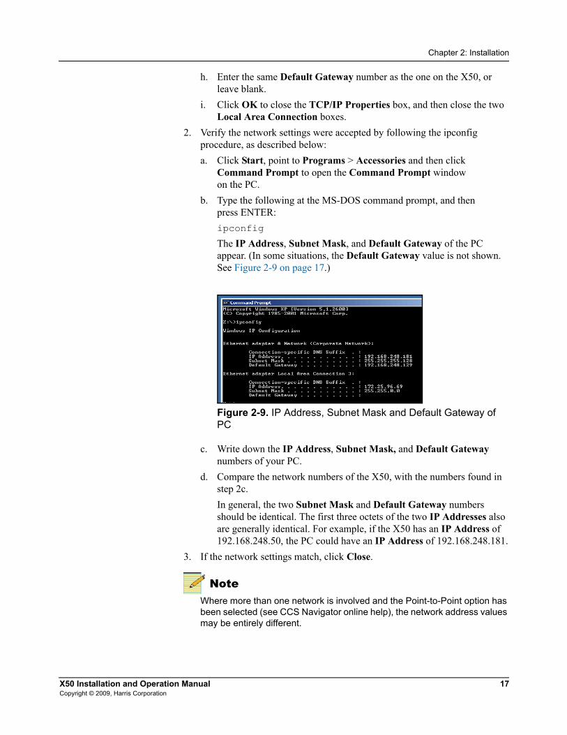
The IP Address, Subnet Mask, and Default Gateway of the PC appear. (In some situations, the Default Gateway value is not shown. See Figure 2-9 on page 17.)
Figure 2-9. IP Address, Subnet Mask and Default Gateway of PC
c. Write down the IP Address, Subnet Mask, and Default Gateway numbers of your PC.
d. Compare the network numbers of the X50, with the numbers found in step 2c.In general, the two Subnet Mask and Default Gateway numbers should be identical. The first three octets of the two IP Addresses also are generally identical. For example, if the X50 has an IP Address of 192.168.248.50, the PC could have an IP Address of 192.168.248.181.
3. If the network settings match, click Close.
NoteWhere more than one network is involved and the Point-to-Point option has been selected (see CCS Navigator online help), the network address values may be entirely different.

18 X50 Installation and Operation ManualCopyright © 2009, Harris Corporation
Chapter 2: Installation
Remote Control of the X50This section provides the following general configuration procedures:• “Preparing for Remote Control via Control Panel” (below)• “Selecting a Remote Unit to Control” on page 19
Figure 2-10. Network Configuration Diagram
Remote PC-based software control and monitoring options
SNMP Web browser Third-party control software
HP OpenviewTM
MicrosoftInternet
Explorer 6.0 or later
CCS Protocol
CCS Navigator
CCS application
X50 broadcast-quality up/cross/downconverter
3rd party hub or switch
multiple path converter/synchronizerX85-3G/X85HD/X75SD
X50 broadcast-quality up/cross/downconverter

X50 Installation and Operation Manual 19Copyright © 2009, Harris Corporation
Chapter 2: Installation
Preparing for Remote Control via Control PanelControl panels remotely control X50 units via broadcast. You will need to configure the switchers and routers in your network accordingly.Follow these steps to prepare your X50 models for remote control:1. Reconfigure each X50 with unique IP addresses and other appropriate
network settings, including shared subnet mask addresses. See “Setting IP and Subnet Mask Addresses” on page 13 for details.
2. Restart each X50, and then wait 20 seconds to allow for network detection.3. Connect all X50 units to a TCP/IP-based network hub or switch using
10/100Base-T Ethernet cable. 4. Discover all units found on the network, and then select the one you wish to
control.
Selecting a Remote Unit to ControlYou can remotely control all X50 units that share the same subnet. Follow these steps:1. Ensure all connections and network settings have been made.2. On the X50, press the Remote button to bring up a list of available units for
control (see Figure 2-11).
Figure 2-11. List of Systems Available for Remote Control
The <local device > option shown on-screen represents the unit you are using (the local unit that is in front of you), and is always available on this list. An asterisk (*) beside the name indicates that this is the remote system currently being controlled by the panel.
NoteInstead of IP addresses, you can give alphabetical names to individual X50 units that will appear in the list. To do this, see the Machine Name parameter.
3. Use the control knob to scroll through the list of available X50 devices, highlight the unit you wish to control, and then press Enter.The X50 screen reads Connecting...
4. Wait a few moments.The menu of the selected X50 unit appears along with all of that unit’s settings.

20 X50 Installation and Operation ManualCopyright © 2009, Harris Corporation
Chapter 2: Installation
5. Operate the selected unit as required. Once a unit is selected for remote control, all front panel features operate as if you were actually at the front panel of the selected remote unit. This means that the VFD panel, status indicators, and buttons (with the exception of the Remote and Option button) all control and/or reflect the status of the remote unit, not the one you are physically operating.
NoteThe light on the Remote button flashes while the unit is remotely controlling a device.
6. To switch to another unit, or to control the local device you are physically operating, press the Remote button, and then select a new device to control.
7. Select <local device > to resume normal single-unit operation.

X50 Installation and Operation Manual 21Copyright © 2009, Harris Corporation
Chapter 2: Installation
Configuring for Web Browser ControlOnce the networking parameters of the X50 have been configured appropriately, and it is connected to the Ethernet network, the built-in Web server allows a standard Web browser to control the frame. Before controlling your frame in this way, note the following system and browser requirements:• The X50 supports Web browsers that are compatible with HTML 4.0
(and later).• Although most standard Web browsers can be used with the X50 for HTTP
control, the following browsers have been tested and approved: Microsoft® Internet Explorer 6.0, Netscape® Navigator™ 7.2, and Mozilla® Firefox™ 1.0.
To select a unit for control, follow these steps:1. Ensure all required connections and network settings have been made
locally on your X50 unit(s).2. Open a supported Web browser, and then type the IP address of the unit you
wish to control into the Address, Location, or URL field of your Web browser (the name of the field depends on the Web browser you are using). For example, type the following to control an X50 unit with this IP address:
http://192.168.100.250

22 X50 Installation and Operation ManualCopyright © 2009, Harris Corporation
Chapter 2: Installation
Configuring SNMP SupportWith SNMP support, you can use a standard MIB browser to monitor parameters and alarms. You must set SNMP options using CCS Pilot or Navigator. Before you can configure SNMP support, you must discover the X50.
Setting SNMP OptionsDevices that support SNMP will have an SNMP tab in the Configuration window. To configure an X50 that supports SNMP, follow these instructions. 1. While your CCS software is in Build mode, right click on the X50 and
choose Configuration. The Configuration window opens.
2. Click the SNMP tab, and then click the Read button. The CCS network polls the module and retrieves its current settings. It fills in all the fields on the SNMP tab of the Configuration window with the settings that are on the device.
Figure 2-12. SNMP Tab on device Configuration Window

X50 Installation and Operation Manual 23Copyright © 2009, Harris Corporation
Chapter 2: Installation
In the top left portion of the window are SNMP Agent settings.
Below the SNMP Agent settings are System settings. The information in these fields describes the device that is currently selected in the Navigation window. This is user-defined information that, once provided by an administrator, is available on the device when it is retrieved by a MIB browser.
The Trap Destination IP Addresses field contains a list of IP addresses that will receive SNMP traps. It is in the format IP Address:Port Address:SNMP version.
3. To add new Trap Destination IP Addresses, see “Adding New Addresses for SNMP Traps” on page 24. To modify them, see “Modifying an SNMP Trap Destination” on page 24.
4. (Optional) If you wish the device to reboot automatically when you send the new configuration to it, place a check beside Reboot device after performing transfer.
5. Click Write to send the new configuration to the device.
Table 2-1. SNMP Agent Fields of SNMP Tab
Field FunctionPort Number (Can be from 0 to 65535) The network port used by
the SNMP agent; port 161 is the default for X50Read Community Has to match the “read community” setting in your
MIB browser
Write Community Has to match the “write community” setting in your MIB browser
Enable Authentication Traps
When checked, authentication traps are sent if the read or write community doesn’t match between the SNMP agent and MIB browser
Enable SNMP Agent
When checked, SNMP support is available; if not checked, SNMP support is disabled
Table 2-2. System Fields of SNMP Tab - MIB-2 System Information
Field ExplanationDescription The default is “Leitch SNMP Agent”
Location The physical location of the device
Contact The contact person for this device
Name Name of the device

24 X50 Installation and Operation ManualCopyright © 2009, Harris Corporation
Chapter 2: Installation
6. If you did not place a check beside Reboot device after performing transfer in step 6, click Reboot now and your changes to the configuration will take effect.
NoteThe device must be rebooted before changes will take effect.
Adding New Addresses for SNMP TrapsTo add a new SNMP trap destination, follow this procedure:1. Click Add beneath the Trap Destination IP Addresses field. The Add
Trap Destination window opens.
Figure 2-13. Add Trap Destination Window
2. Choose the SNMP version that you would like to use for traps. 3. Choose the IP address of that trap destination. 4. Choose the port number. The default is 162, but an administrator can set this
to any number between 0 and 65535. 5. Click Apply. A new line is added in the Trap Destination IP Addresses
field. 6. Repeat steps 2 through 5 to add more rows to the window. 7. Click OK to return to the SNMP tab of the Configuration window.
Modifying an SNMP Trap DestinationTo modify a trap destination, follow this procedure:1. In the Trap Destinations IP Addresses list, click on the item you would
like to modify.

X50 Installation and Operation Manual 25Copyright © 2009, Harris Corporation
Chapter 2: Installation
2. Click the Modify button. The Modify Trap Destination window opens.
Figure 2-14. Modify Trap Destination Window
3. Choose the SNMP version of the traps using the radio buttons at the top of the window.
4. Enter the IP address of that trap destination in the IP Address field.5. Enter the port number in the Port Number field.
The default value is 162.6. Click Apply. The selected entry in the Trap Destination IP Addresses
field is updated. 7. Repeat steps 2 through 6 to further update the row. 8. Click OK to close the Modify Trap Destination window.
Configuring Third-Party SNMP Software Control SNMP is an industry-standard protocol that allows other manufacturers’ control software to remotely monitor and control the X50.Harris provides MIB files that can be downloaded from the website. Two general MIB files (leitch.mib and ccsAlarm.mib) set up the structure to define parameters and alarms. Once these two MIBs are installed, you will want to install a MIB for each distinct module for which you wish to set up third-party software control.You can use any standard MIB browsing software with your X50. 1. Make the required network connections between the X50 unit(s) and your
PC with installed SNMP browser/control software.The SNMP configuration process for the X50 directs the SNMP agent where to send alarms (SNMP traps). This file must be modified before it is loaded back to the X50. For information on configuring SNMP, see page 22.
2. Load the leitch.mib file into your SNMP browser/control software.This MIB sets up the basic structure for product specific Harris MIBs. It can be found under the Private > Enterprise branch, and sets up the leitchProducts and leitchCommon sub-branches. The leitchCommon branch is initially empty. The leitchProducts branch contains folders for different families of Harris devices—for example, LeitchX75, NEO and X50.

26 X50 Installation and Operation ManualCopyright © 2009, Harris Corporation
Chapter 2: Installation
3. Load ccsAlarm.mib into your SNMP browser/control software.This MIB adds a ccsAlarms sub-branch to the leitchCommon folder. When it is installed, you will be able to receive traps with proper information as to where the alarms are triggered from.
4. Load product-specific X50 MIB files into your SNMP browser/control software.A product-specific MIB provides a clear path to the parameters and alarms on the device. Harris MIBs can be downloaded from our website.X50 MIBs will appear in the X50 folder under the leitchProducts folder. See Figure 2-15 on page 27.
5. Configure your MIB browser to connect to the unit by entering the IP address, Port (if you have changed the Port from its default in the configuration), and other standard configuration settings.
Your browser should now be able to connect to the SNMP agent running on the X50 unit. If you wish to receive traps, start up the trap receiver in your MIB browser software.
NoteTo verify that your configurations are correct, you can walk MIB2.

X50 Installation and Operation Manual 27Copyright © 2009, Harris Corporation
Chapter 2: Installation
Monitoring and Control Using MIBsEach X50 unit’s MIB can be fully expanded. When you expand an X50 MIB node in the tree view, there are three sub-folders (see Table 2-3).
To view a complete list of the parameter settings on the X50, walk the MIB for that X50, walk the X50 at an IP address, or walk the X50 type.
Figure 2-15. Typical MIB Loaded into NuDesign MIB Browser
Table 2-3. MIB Sub-Folders
Tree View Item Contents
Objects Lists the parameters for the device; all configurable and read-only parameters appear here (see Figure 2-15)
Identities Lists the alarms information for the device which is used by the MIB browser to make trap messages more meaningful (see “Alarms in MIB Browser” on page 28.)
Conformities A group of standard MIB information that guarantees that the MIB conforms to standard SNMP format

28 X50 Installation and Operation ManualCopyright © 2009, Harris Corporation
Chapter 2: Installation
Navigating Parameters in a Leitch MIBX50 MIBs make it possible to view a parameter’s range, walk a device or a frame, or receive alarm traps for a device (see Figure 2-16). For details on accessing these features, see the documentation that accompanies your third-party control software.
Figure 2-16. Alarms in MIB Browser
Parameters that have a limited list of options have two listings under the Entry branch of the tree. Parameters that have a range (as in a slider) of options have four listings under the Entry branch of the tree.
For information on the parameters for each individual device, see that device’s documentation, posted on our website. Some Harris products have HTML forms that display their parameters, and these are also posted on our website.
Table 2-4. Sub-Branches Under a Parameter in a Leitch MIB
Sub-Branch ContainsSlot ID (Does not apply to the X50)
Value The current setting of this parameter
High Range (slider ranges only)
The top value of this parameter
Low Range (slider ranges only) The bottom value of this parameter

X50 Installation and Operation Manual 29Copyright © 2009, Harris Corporation
Chapter 3
Controls
OverviewYou can control the X50 using many different interfaces:• Local front panel X50 controls• Remote front panel controls on other X50 units• CCS Level 3-enabled control hardware and software products• X50 Web browser
Front Panel ControlsThe X50 supports local and remote front panel control, CCS software, CCS-enabled controls panels, SNMP, and web browsers. At the control panel, you can change parameters using the rotary switch, push buttons, status LEDs, and VFD. When using the control panel, you will find some entries in the main menu begin with a + symbol. This indicates there are multiple levels for that item. Complete lists of basic and advanced control parameters are available in the X50/X75/X85 CD-ROM package.
Figure 3-1. X50 Controls and LEDs
Rotary knob
Pushbuttons
LEDs

30 X50 Installation and Operation ManualCopyright © 2009, Harris Corporation
Chapter 3: Controls
Pushbuttons
LEDsWhen LEDs are lit, the item next to the LED is either selected, enabled, or present. A flashing LED indicates the item is in an error condition. An LED that remains unlit is either not applicable, or—in the case of Rate—indicates an output frame rate of 50. Table 3-2 provides additional information about the left-side LEDs.
Table 3-1. Pushbutton Controls
Name FunctionEnter Selects or “takes” an option or value in a parameter
Exit Exits from one level in the parameter tree to a higher lever in the tree
Default Resets all of the X50 parameters to their default values, and flashes when you have selected a default value for a parameter (to reset all of the parameters using this control, you must press and hold the button for one second)
Remote Enables the controls to operate other remote X50, X75, and X85 units (to activate this control, you must press and hold the button for one second)
Status Displays the current machine status and/or error conditions (the VFD switches back to control mode to display the menu structure when you press the Enter or Exit button; hold the button for one second to obtain a list of alarms and their options)
Help Displays a brief description of a selected parameter’s function (hold the button for one second to view the control panel’s display options)
Table 3-2. Left-Side LEDs
Name Meaning when LitPower 1 and Power 2 Indicates which power supplies are in use
Mem Active Shows that the internal or SD card memory is in use; normal operation of the X50 may be interrupted
Audio Card Indicates the presence of an advanced audio module (future use)
Upgrading Indicates the X50 software is being upgraded; normal operation is interrupted

X50 Installation and Operation Manual 31Copyright © 2009, Harris Corporation
Chapter 3: Controls
Main Menu Items
Advanced ControlsAdvanced controls are designed for unusual applications, providing exceptional flexibility for the demands of professional video production facilities.
NoteWhen you disable Advanced Controls in the System Setup menu, those controls are hidden from view in the web browser.
Figure 3-2. Web Browser With Advanced Controls Disabled
Table 3-3. Main Menu
Name FunctionVideo Provides parameters for changing video settings
Audio Provides parameters for changing audio settings
Reference Sets the reference standard for the system
System Setup Sets the options for general system setup; also includes network IP addresses, factory recall , and entry to the advanced controls
Input Video Select Selects the video source to be processed
SDI 1 Output Format Selects the output video format on SDI 1
SDI 2 Output Format Selects the output video format on SDI 2
Analog/HDMI Output Select
Selects the video source for the analog/HDMI video outputs
Output Frame Rate Sets the output frame rate
Input Audio Select Selects the source audio to be processed

32 X50 Installation and Operation ManualCopyright © 2009, Harris Corporation
Chapter 3: Controls
If you are using the web browser control and need to enable the Advanced Controls mode, you must refresh the browser to have the full set of menu items appear on the left panel. Similarly, after disabling the Advanced Controls mode, you should refresh the browser to have the full set of menu items disappear on the left panel. Otherwise, these menu items will bring you to blank pages.

X50 Installation and Operation Manual 33Copyright © 2009, Harris Corporation
Chapter 3: Controls
Aspect Ratio ConversionYou can set the output aspect ratio conversion using Custom, Standard, or Automatic controls. These three methods are found in the ARC Preset parameter, with the following options.• Custom• Standard ARCs
• Anamorphic• 4:3 Pillar Box• 14:9 Pillar Box• 16:9 Cut• 4:3->21:9 Ltr• 16:9 Letter Box• 14:9 Letter Box• 4:3 Cut• 16:9->21:9 Ltr
• Automatic ARCs• AFD• AFD - ALTR• VI• VI - ALTR• WSS• WSS - ALTR
Depending on the current conversion mode (Up, Down, Cross, or SD-ARC), different subsets of these options will be in effect. Thus, for example, an ARC setting that is visible in upconversion may not be visible in downconversion.
Custom ARCTo make a custom ARC setting, select options in the Advanced, Variable, and Crop parameters of Scalar 1 and Scalar 2.
NoteWhen individual values are matched with a particular pre-defined standard aspect ratio, ARC Preset will change, to reflect that matching standard aspect ratio.
Automatic ARCActive Format Description (AFD), Video Index (VI), and Wide-Screen Signalling (WSS) are different systems in which embedded data automatically control the output aspect ratio. When you set ARC Preset to AFD, AFD-ALTR, VI, VI-ALTR, WSS, or WSS-ALTR, the X50 converts the aspect ratio according to the upstream AFD, VI, or WSS code. The x-ALTR versions of these options interpret the code in an alternative way.

34 X50 Installation and Operation ManualCopyright © 2009, Harris Corporation
Chapter 3: Controls
AFD transmits data in the VANC space of the SDI signal, enabling both 4:3 and 16:9 television monitors to optimally present video with preset ARC and safe area information. Without AFD, converted video may appear distorted or “cut off” when it appears on different monitors. See Figure 3-3 on page 34 for a comparison of AFD and non-AFD aspect ratio conversion.
Figure 3-3. AFD and Non-AFD ARC
VI provides embedded code in 525-line and 625-line component digital video signals. This code makes it possible for picture and program related source data to be carried in conjunction with a video signal.WSS is embedded code in a 625-line system. It contains information on the aspect ratio range of the transmitted signal and its position as it would appear on a conventional 4:3 display.Figure 3-5 on page 36 and Figure 3-6 on page 37 show the different AFD, VI, and WSS code selections. Figure 3-4 on page 35 explains the meanings of the diagrams.
SD-SDI 4:3 HD-SDI 16:9
Full frame Pillarbox
DownUp
Postage stamp
Full frame
SD-SDI 4:3
16:9 Letterbox
SD-SDI 4:3
Up
Postage stamp
Full frame
HD 16:9
Using active format description (best result)
Without active format description (undesirable result)
Using active format description, the original image
information is maintained throughout the entire
conversion , creating the best possible viewing area .

X50 Installation and Operation Manual 35Copyright © 2009, Harris Corporation
Chapter 3: Controls
Figure 3-4. AFD Diagram Explanation
Bounding box representsthe coded frame.
The smallest rectangle enclosingthe white regions indicates the areaof essential picture information.
Black regions indicate areasof the picture that do notcontain useful information andshould be cropped by thereceiver where appropriate.
Gray regions indicate areas of the picturethat may be cropped by the receiverwithout significant loss to the viewer.

36 X50 Installation and Operation ManualCopyright © 2009, Harris Corporation
Chapter 3: Controls
Figure 3-5. AFD Descriptions for 4:3
AFD 4:3 code and description
Illustration in a4:3 coded frameWSS name
16:9 Top
14:9 Top
>16:9
Full Frame
16:9 Center
14:9 Center
Full A 14:9
None
None
Description
Image with a 16:9 aspect ratio and with analternative 4:3 center as a vertically centered
letterbox in a 4:3 coded frame
alternative 14:9 center as a vertically centeredImage with a 16:9 aspect ratio and with an
letterbox in a 4:3 coded frame
Image with a 4:3 aspect ratio and with analternative 14:9 center in a 4:3 coded frame
Image with 14:9 aspect ratio as a verticallycentered letterbox in a 4:3 coded frame
Image with a 16:9 aspect ratio as a verticallycentered letterbox in a 4:3 coded frame
Image is full frame, with an aspect ratio that isthe same as the 4:3 coded frame
Image with aspect ratio greater than 16:9 asa vertically centered letterbox in a 4:3 coded
frame
Image with a 14:9 aspect ratio as letterbox atthe top of a 4:3 coded frame
Image with a 16:9 aspect ratio as letterbox atthe top of a 4:3 coded frame
AFD and VI Select parameter options
16:9 Top
14:9 Top
>16:9 in 4:3
16:9 L
14:9 L
4:3 Full
4:3 A 14:9
16:9 L A 4:3
16:9 L A 14:9

X50 Installation and Operation Manual 37Copyright © 2009, Harris Corporation
Chapter 3: Controls
Figure 3-6. AFD Descriptions for 16:9
AFD 16:9 code and description
Illustration in a16:9 coded frame
>16:9 in 16:9AFD Code: 0100
AFD and VI Select parameter options
16:9 A 4:3AFD Code: 1111
14:9 PAFD Code: 1011
4:3 P A 14:9 AFD Code: 1101
16:9 A 14:9 AFD Code: 1110
16:9 Full AFD Code: 1000
16:9 PrtctdAFD Code: 1010
4:3 P AFD Code: 1001
None
WSS name
None
None
None
None
Anamorphic
None
None
Description
Image with a 16:9 aspect ratio and withan alternative 4:3 center in a 16:9 coded
frame
Image with a 16:9 aspect ratio and withan alternative 14:9 center in a 16:9
coded frame
Image with a 4:3 aspect ratio and with analternative 14:9 center as a horizontallycentered pillarbox image in a 16:9 coded
frame
Image with a 14:9 aspect ratio as ahorizontally centered pillarbox image
in a 16:9 coded frame
Image is full frame, with a 16:9 aspectratio and with all image areas protected
Image with a 4:3 aspect ratio as ahorizontally centered pillarbox image
in a 16:9 coded frame
Image is full frame, with an aspect ratiothat is the same as the 16:9 coded
frame
Image with aspect ratio greater than 16:9as a vertically centered letterbox in a
16:9 coded frame

38 X50 Installation and Operation ManualCopyright © 2009, Harris Corporation
Chapter 3: Controls
Examples of Automatic Aspect Ratio ConversionYou can enable automatic ARC controls by setting the ARC Preset parameter to AFD, AFD-ALTR, VI, VI-ALTR, WSS, or WSS-ALTR. When you set ARC Preset to AFD and the upstream video has AFD code embedded in it, the system will present the video signal in the appropriate aspect ratio, and generate new downstream AFD code accordingly. (You can confirm that AFD is available in the input signal by checking the AFD Present parameter.)For example, in upconversion mode, an upstream signal with an AFD code of 1000 indicates the output will be a full frame 4:3 image. The X50 creates a 4:3 Pillar Box arc, and the output HD image becomes a 4:3 pillar box. The resulting AFD code becomes 1001 (4:3 center).In another example, the X50 is in downconversion mode. The upstream signal has AFD code 1111, indicating a 16:9 ratio with alternative 4:3 center. If you set the ARC Preset parameter to AFD, the X50 creates an output of 16:9 letter box and the resulting AFD code becomes 1111. If you set ARC Preset to AFD-ALTR, system does a center cut ARC, the output becomes 4:3 full, and the resulting AFD code becomes 1000. This result is commonly used in the USA.Figure 3-7 on page 39 to Figure 3-10 on page 42 show all of the conversion patterns.In the event that the current ARC is controlled by AFD, VI or WSS, and this data disappears from the input signal, the X50 provides you with two options:• Retain the current aspect ratio as set by the last AFD, VI, or WSS data.• Reset to the aspect ratio settings that were in use before the AFD, VI, or
WSS data took controlThe Auto ARC Reset parameter controls this feature. Select Yes to have the module reset to older values in the event of loss of data; select No (the default) to retain the current ARC.Some AFD code “encourages” cropping out some of the active video area. To prevent this, set AFD Crop Enable to Disable.The Out Aspect Ratio parameter controls the output aspect ratio of the SD signal, and it will affect how the AFD performs the automatic conversion. (It is assumed that an SD signal may be either 4:3 or 16:9, but an HD signal will always have a 16:9 ratio.) The default value of the Out Aspect Ratio parameter is 4:3.
Output AFD, VI and WSSYou can insert AFD, VI and WSS data into an output video stream either manually or automatically. This function is controlled by the AFD Control, VI Control, and WSS Control parameters. If you are using VI according to the SMPTE proposed RP-186+ standard as of January 11, 2007, you must ensure you have enabled the standard by setting Enable AFD in VI, (located in the same path as the other output control).

X50 Installation and Operation Manual 39Copyright © 2009, Harris Corporation
Chapter 3: Controls
Figure 3-7. 4:3 to 16:9 Conversion
4:3 to 16:9 conversion
Illustration in a4:3 coded frameWSS name
16:9 Top
14:9 Top
>16:9
Full Frame
16:9 Center
14:9 Center
Full A 14:9
None
None
AFD and VI Select parameter options
16:9 Top
14:9 Top
>16:9 in 4:3
16:9 L
14:9 L
4:3 Full
4:3 A 14:9
16:9 L A 4:3
16:9 L A 14:9
Conversion Conversion (Alternative)

40 X50 Installation and Operation ManualCopyright © 2009, Harris Corporation
Chapter 3: Controls
Figure 3-8. 4:3 to 4:3 Conversion
4:3 to 4:3 conversionConversion(Alternative)Conversion
Illustration in a4:3 coded frameWSS name
16:9 Top
14:9 Top
>16:9
Full Frame
16:9 Center
14:9 Center
Full A 14:9
None
None
AFD and VI Select parameter options
16:9 Top
14:9 Top
>16:9 in 4:3
16:9 L
14:9 L
4:3 Full
4:3 A 14:9
16:9 L A 4:3
16:9 L A 14:9

X50 Installation and Operation Manual 41Copyright © 2009, Harris Corporation
Chapter 3: Controls
Figure 3-9. 16:9 to 4:3 Conversion
16:9 to 4:3 conversion
Illustration in a16:9 coded frame
Conversion (Alternative)Conversion
AFD and VI Select parameter options
>16:9 in 16:9AFD Code: 0100
16:9 A 4:3AFD Code: 1111
14:9 PAFD Code: 1011
4:3 P A 14:9 AFD Code: 1101
16:9 A 14:9 AFD Code: 1110
16:9 Full AFD Code: 1000
16:9 PrtctdAFD Code: 1010
4:3 P AFD Code: 1001
None
WSS name
None
None
None
None
Anamorphic
None
None

42 X50 Installation and Operation ManualCopyright © 2009, Harris Corporation
Chapter 3: Controls
Figure 3-10. 16:9 to 16:9 Conversion
16:9 to 16:9 conversionConversion (Alternative)ConversionIllustration in a
16:9 coded frame
>16:9 in 16:9AFD Code: 0100
AFD and VI Select parameter options
16:9 A 4:3AFD Code: 1111
14:9 PAFD Code: 1011
4:3 P A 14:9 AFD Code: 1101
16:9 A 14:9 AFD Code: 1110
16:9 Full AFD Code: 1000
16:9 PrtctdAFD Code: 1010
4:3 P AFD Code: 1001
None
WSS name
None
None
None
None
Anamorphic
None
None

X50 Installation and Operation Manual 43Copyright © 2009, Harris Corporation
Chapter 3: Controls
Closed Captioning and DVB Teletext CaptioningAlthough North America has dedicated standards for closed captioning of video (EIA-608 and 708), many countries in Europe and elsewhere have not yet adopted formal standards. For these countries, closed captioning is part of the DVB Teletext System as described in ITU-R BT-653-3. These specifications define all Teletext Systems (Systems A, B, C, D) used in the world and are also known as the World System Teletext (WST). A Teletext system is made of several pages of various data information and CC data is described in one these pages. System B is used in Australia, the UK, and Germany, among other countries.Australian closed captions are inserted on line 21/334 in analog PAL broadcast signals, as per the ITU-R BT-653-3. When analog PAL is produced or converted to SDTV (625 digital), a digitized version of the closed captioning appears on line 21/334 (in the same way line 21 on NTSC signals is digitized and appears on the line 21 of SD-SDI signals). The document proposed by Free TV Australia indicates how to carry this CC data into the VANC area of SD-and HD-SDI signals by use of the SMPTE 334M VANC embedding protocol. For digital broadcasting, Australia intends to use the ETSI EN 300 472 standard that specifies the conveyance of ITU-R System B Teletext in DVB bit streams.Closed Captioning and Teletext data that is embedded in the input stream is detected by the CC/TT Present parameter. This information is re-embedded into output video stream when you set the CC/TT Embed parameter to On.
Color CorrectionThe color corrector changes the following attributes of an input signal:• Gain• Offset• White Slope • Black Stretch • Gamma Correction These parameters include “lock” options that make it possible for you to adjust all of the options of a particular group in tandem, rather than separately.
White Slope and Black StretchThe white slope is comprised of G White Knee, B White Knee, R White Knee, and GBR White Knee Lock. Black Stretch includes G Black Knee, B Black Knee, R Black Knee, and GBR Black Knee Lock.Component knees determine the amount of additional gain applied to segments at the ends of the RGB transfer functions in the look-up tables.

44 X50 Installation and Operation ManualCopyright © 2009, Harris Corporation
Chapter 3: Controls
The values displayed are a percent of the available correction. A positive white knee increases the slope of the last 15% of RGB values, and decreases the slope of the preceding 15%. A positive black knee parameter will increase the slope of the first 15% of the transfer function by the amount entered and decrease the slope of the next 15%, to return to the unmodified transfer function. Each component knee is added to the total knee (the sum cannot exceed 100%) to produce the correction applied to the respective component.
Figure 3-11. Examples of Increased and Decreased White Slope
White Slope
Details in bright
areas are less
visibile
Details in bright
areas are more
visibile
Normal white knee
Decreased white knee
Increased white knee
Out
put
Input
X50 Installation and Operation Manual 45Copyright © 2009, Harris Corporation
Chapter 3: Controls
Figure 3-12. Increased and Decreased Black Knees
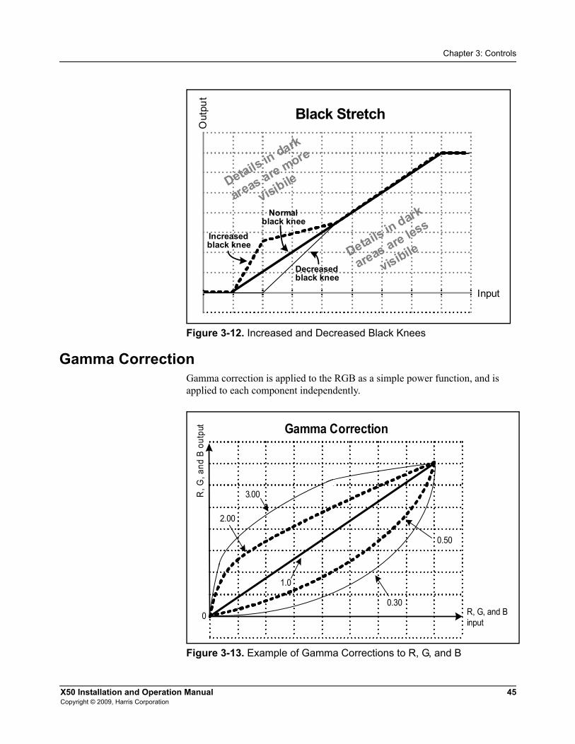
Gamma CorrectionGamma correction is applied to the RGB as a simple power function, and is applied to each component independently.
Figure 3-13. Example of Gamma Corrections to R, G, and B
Black Stretch
Details in dark
areas are less
visibile
Details in dark
areas are more
visibile
Out
put
Input
Normal black knee
Increased black knee
Decreased black knee
Gamma Correction
0
R, G
, and
B o
utpu
t
R, G, and Binput
0.30
0.50
1.0
2.00
3.00

46 X50 Installation and Operation ManualCopyright © 2009, Harris Corporation
Chapter 3: Controls
Custom Splash ScreenYou can add your station’s logo or any other graphic to the startup splash screen on the VFD of the X50. To add a custom graphic, follow these steps:1. Create a 24-bit Windows bitmap file of the size 128x32, using a graphics
program.2. If the logo has a background color of black, save the bitmap file as
logo.bmpOrIf the logo has a background of white, save the bitmap file as logo-i.bmp (the application will invert the colors of the logo before displaying).
3. Upload the file via Navigator’s file transfer tab (or via FTP) to /config4. Reboot the X50 to see the logo displays briefly.
NoteIf both logo.bmp and logo-i.bmp exist and are valid images, logo.bmp will be used.
Limitations on the Secondary ChannelThe second video channel of the X50 is subject to certain timing limitations.H-Phase and V-Phase parameters make it possible to adjust reference signals for a wide range of formats. However, these parameters control the timing for both channels of video. The two video channels cannot be phased independently of each other. The ranges of the H-Phase and V-Phase parameters are based on the output standard of the primary channel.Similarly, the Audio/Video Sync parameter provides automatic tracking of the audio and video signals (see Figure 3-15 on page 49). However, this timing is based on the output of the primary channel. Different formats may have different propagation delays, and thus, caution may be needed to ensure the secondary channel audio and video tracking is correct.
Auto Route FeatureThe X50 is designed to automatically route an alternate video source if the Primary Input selection fails. The Backup Input 1 selection is the first alternate video source; if that source fails, the next priority is given to the selected source in Backup Input 2. The Auto Switch Delay parameter makes it possible for you to set the amount of delay before the X50 switches to the next backup input. The adjustable range is between 0 and 5 seconds.If the Primary Input signal returns when the X50 is routed to Backup Inputs 1 or 2, the X50 reverts to the Primary Input signal. The Auto Route feature is only available in the Advanced Controls mode.

X50 Installation and Operation Manual 47Copyright © 2009, Harris Corporation
Chapter 3: Controls
Proc BypassProc Bypass is an option found in the SDI1 Out Format and SDI2 Out Format parameters. In the X50, this function bypasses the scalar and all processing (noise reduction, detail enhancement, color correction, etc.) but is downstream of the frame synchronization.
Audio ProcessingThe Input Audio Select parameter selects the audio source to be routed to all audio outputs. This pre-empts individual audio controls. The default Map Through option routes demux audio to mux and HDMI outputs, and AES audio to AES and analog outputs.Figure 3-15 on page 49 shows the audio routing in the X50. The AES Present, Analog Present, and DMX Channel Present read-only parameters display the status of the incoming audio feeds. When you select these parameters, each of the eight channels is displayed as a symbol. The AES Present parameter has a unique feature that notifies you when an AES signal is available for that channel (visible as a P symbol on the channel), but the channel has been set to an analog input.See Figure 3-14 on page 47 for an explanation of these symbols .
CautionThe analog audio output of the X50 is always low-impedance. To ensure that you do not overload the audio output, always connect to high impedance downstream.
Figure 3-14. Audio Status Parameters
DMX Present = = A A D D = =
No signal present
Audio present
Data present
No signal present
Analog Present = = = = = = A A
AES Present = = A A D D P P
No signal present
Data present
Audio present (but not selected)
Audio present
Analog audio present

48 X50 Installation and Operation ManualCopyright © 2009, Harris Corporation
Chapter 3: Controls
Audio MetadataThe audio metadata feature de-embeds audio metadata from various sources and then re-embeds the audio metadata into multiple outputs.The audio metadata source may be one of the following:• Metadata embedded in SDI (Methods A and B)• Input of the serial port• Metadata generatorThe audio metadata may be inserted into the following outputs:• SDI 1 and SDI 2 (Methods A and B)• Serial portOnce the source is selected, it applies to all of the outputs.

X50 Installation and Operation Manual 49Copyright © 2009, Harris Corporation
Chapter 3: Controls
Figure 3-15. X50 Audio Routing
Audi
o sy
nc
and
dela
y
SRC
s 9
to 1
2
AES
1 in
AES
4 in
AES
3 in
AES
2 in
Ana
log
1 in
Ana
log
4 in
Anal
og 3
in
Ana
log
2 in
SR
Cs
1 to
8
Dem
ux 1
Dem
ux 8
Dem
ux 7
Dem
ux 6
Dem
ux 5
Dem
ux 4
Dem
ux 3
Dem
ux 2
8 pa
irs
4 pa
irs
Test
gen
erat
or•
400
Hz
•10
00 H
z•
2000
Hz
•40
00 H
z•
SM
PTE
RP
155
•E
BU
R68
Out
put
rout
er12
pai
rs
Aud
io p
roc
gain
an
d in
vert
(16-
chan
nel)
Aud
io p
roc
gain
an
d in
vert
(16-
chan
nel)
Aud
io p
roc
gain
an
d in
vert
(8-c
hann
el)
Aud
io p
roc
gain
an
d in
vert
(8-c
hann
el)
Aud
io p
roc
gain
an
d in
vert
(8-c
hann
el)
4 AE
S o
ut
(8-c
hann
el a
udio
)
Vide
o ou
t 1(1
6-ch
anne
l mux
out
put )
Vid
eo o
ut 2
(16-
chan
nel m
ux o
utpu
t )
Bala
nced
ana
log
out
(8-c
hann
el a
udio
)
HD
MI o
ut
(8-c
hann
el a
udio
)

50 X50 Installation and Operation ManualCopyright © 2009, Harris Corporation
Chapter 3: Controls

X50 Installation and Operation Manual 51Copyright © 2009, Harris Corporation
Chapter 4
Specifications
Conversion CapabilitiesThe X50 can convert any of the input signals and formats listed in Table 4-1 to any of the specified output signals and formats. (The symbol Y indicates that the designated format conversion is supported.).
Table 4-1. X50 Supported Conversion Formats
Outputs
486i/ 59.94
720p/ 59.94
1080i/ 59.94
1080p/ 23.98*
1080p/59.94
1080p/ 59.94 DL*
576i/ 50
720p/ 50
1080i/ 50
1080p/ 25
1080p/50
1080p/ 50 DL*
Inpu
t
480i/59.94 Y Y Y Y2 Y Y
720p/59.94 Y Y Y Y2 Y Y
1080i/59.94 Y Y Y Y2 Y Y
1080p/23.98 Y1 Y1 Y1 Y Y1 Y1
1080psf/23.98 Y1 Y1 Y1 Y Y1 Y1
1080p/59.94 Y Y Y Y2 Y Y
1080p/59.94 DL*
Y Y Y Y2 Y Y
576i/50 Y Y Y Y Y Y
720p/50 Y Y Y Y Y Y
1080i/50 Y Y Y Y Y Y
1080p/25 Y Y Y Y Y Y
1080p/50 Y Y Y Y Y Y
1080p/50 DL* Y Y Y Y Y Y
Y1 indicates that 2:3 cadence is used; Y2 indicates material with 3:2 cadence converted with no motion artifacts* DL = Dual Link 3 Gb/s and Level B 3 Gb/s

52 X50 Installation and Operation ManualCopyright © 2009, Harris Corporation
Chapter 4: Specifications
Video Input
3G/HD/SD-SDI
Fiber (OP+SFP+TR13P Module)
Table 4-2. 3G/HD/SD-SDI Input Video Specifications
Item SpecificationNumber of inputs 2
Standard • 3G: SMPTE 424M (2.97, 2.97/1.001 Gb/s)• HD: SMPTE 292M (1.485, 1.485/1.001 Gb/s)• SD: SMPTE 259M-C (270 Mb/s, 525/625 component video)
Connector BNC (IEC169-8)
Impedance 75Ω
Return loss • >10 dB, typical, from 5 MHz to 2970 MHz• >15 dB, typical, from 5 MHz to 1485 MHz• >20 dB, typical, from 5 MHz to 270 MHz
Equalization • 3G: Adaptive cable equalization for up to 164 ft (50 m), typical, of Belden 1694A co-axial cable
• HD: Adaptive cable equalization for up to 492 ft (150 m) typical, of Belden 1694A co-axial cable
• SD: >23 dB Belden 8281 co-axial cable
Table 4-3. Fiber Input Specifications
Item Minimum Typical Maximum NoteNumber of LC connector inputs
- - 1
Input wavelength 1260 nm - 1620 nm
Optical power monitor accuracy
-2 dB 0 2 dB
Sensitivity at 270 Mb/s(SMPTE 259M)
- -22 dBm -20 dBm Pathological
Sensitivity at 1.5 Gb/s (SMPTE 292M)
- -22 dBm -19 dBm Pathological
Sensitivity at 3 Gb/s (SMPTE 424M)
- -19 dBm -18 dBm Pathological
Overload 0 dBm - - BER = 1E-12 against SDI matrix check field signals for video applications. BER = 1E-12 against PRBS 223-1 for datacom applications.

X50 Installation and Operation Manual 53Copyright © 2009, Harris Corporation
Chapter 4: Specifications
S-Video
Composite Video
Component Video
Table 4-4. S-Video Input Specifications
Item SpecificationStandard • NTSC
• PAL-B• PAL-M
Connector 4-pin DIN
Table 4-5. Composite Video Input Specifications
Item SpecificationStandard • NTSC (SMPTE 170M)
• PAL-B (ITU 624-2)• PAL-M
Connector BNC (IEC 169-8)
Input level 1.0 V pk-to-pk
Impedance 75Ω
Return loss >40 dB, 0.1 MHz to 6 MHz
Common mode range 5.0 V
CMRR 60 dB @ 50/60 Hz, 5 V pk-to-pk
Table 4-6. Component Video Input Specifications
Item SpecificationFormat Betacam/SMPTE
Connector BNC (IEC 169-8)
Input level 1.0 V pk-to-pk
Impedance 75Ω
Return loss >40 dB, 1 kHz to 6 MHz

54 X50 Installation and Operation ManualCopyright © 2009, Harris Corporation
Chapter 4: Specifications
Genlock
Table 4-7. Genlock Input Specifications
Item SpecificationConnector BNC (IEC169-8)
Impedance 75Ω
Return loss • >40 dB (typical) to 6 MHz• >35 dB (typical) to 30 MHz
Common mode range 5.5 V pk-to-pk
CMRR 60 dB @ 60Hz, 5 V pk-to-pk
Input level • 1 V pk-to-pk, -5.0 dB to +6.0 dB for NTSC/PAL-B• ±300 mV, -3.5 dB to +6.0 dB for Tri-Level Sync:
• 1080i: 59.94/50• 1080p: 29.97/25
Signal type • NTSC/PAL-B Analog Composite• ±300 mV Tri-Level Sync
Standard • SMPTE 170M (NTSC)• ITU-R BT.470-6 (PAL-B)• SMPTE 274M (1080i, 1080p)

X50 Installation and Operation Manual 55Copyright © 2009, Harris Corporation
Chapter 4: Specifications
Video Output
3G/HD/SD-SDI
Table 4-8. 3G/HD/SD-SDI Output Video Specifications
Item SpecificationNumber of outputs 2
Standard • 3G: SMPTE 424M (2.97, 2.97/1.001 Gb/s)• HD: SMPTE 292M (1.485, 1.485/1.001 Gb/s)• SD: SMPTE 259M-C (270 Mb/s, 525/625 component
video)
Connector BNC (IEC169-8)
Impedance 75Ω
Return loss • >10 dB, typical, from 5 MHz to 2970 MHz• >15 dB, typical, from 5 MHz to 1485 MHz• >20 dB, typical, from 5 MHz to 270 MHz
Signal level 800 mV ± 10%
DC offset 0.0V ± 0.5 V
Rise and Fall Time • 3G: <135 ps (20% to 80%)• HD: <270 ps (20% to 80%)• SD: 400 - 1500 ps (20% to 80%)
Overshoot < 10% of amplitude (all outputs terminated)
Jitter • Timing jitter:• 3G: <2 UI peak to peak• HD: <1 UI peak to peak• SD: <0.2 UI peak to peak
• Alignment jitter:• 3G: <0.3 UI peak to peak• HD: <0.2 UI peak to peak• SD: <0.2 UI peak to peak

56 X50 Installation and Operation ManualCopyright © 2009, Harris Corporation
Chapter 4: Specifications
Fiber (OP+SFP+TR13P Module)
HDMI
Table 4-9. Fiber Output Specifications
Item Minimum Typical Maximum Note*Number of LC connector outputs
- - 1
Standards • 3G: SMPTE 424M• HD: SMPTE 292M• SD: SMPTE 259M
Peak wavelength 1280 nm 1310 nm 1340 nm Measured at 25°C
Spectrum width (RMS) - 1.5 nm 3 nm
Average output power -7 dBm - 0 dBm
Optical rise/fall time (3G HD-SDI)
- 105/120 ps 165/180 ps
Extinction ratio 5dB 7 dB -
Jitter - <110 ps 180 ps SD-SDI Pathological
- <60 ps 100 ps 1.5 G SDI Pathological
- <45 ps 70 ps 3G HD-SDI Pathological
Laser safety level Class 1
* Rise and fall times, 20% to 80%, are measured following a fourth-order Bessel-Thompson filter with a bandwidth of 0.75 x clock frequency corresponding to the serial data rate.
Table 4-10. HDMI Output Specifications
Item SpecificationNumber of outputs 1
Standards • 525• 625• 1080i/59.94• 1080i/50
• 1080p/23.98• 720p/59.94• 720p/50
Connector HDMI
Compliance HDMI 1.3

X50 Installation and Operation Manual 57Copyright © 2009, Harris Corporation
Chapter 4: Specifications
S-Video
Composite Video
Table 4-11. S-Video Output Specifications
Item SpecificationStandard • NTSC
• PAL-B• PAL-M
Connector 4-pin DIN
Table 4-12. Composite Video Output Specifications
Item SpecificationStandard • NTSC
• PAL-B• PAL-M
Connector BNC (IEC 169-8)
Resolution 12 bits
Impedance 75Ω
Return Loss >40 dB, 0.1 MHz to 6 MHz
Frequency response -1.6 dB at 6 MHz
DC offset <0.5 mV
Differential gain <0.5%
Differential phase ≤ 1.2° pk-to-pk
Y/C gain <1°, typical
Y/C delay • <10 ns (NTSC)• <23.1 ns (PAL)
Transient response <0.5% K Factor
SNR 63 dB, typical, luma ramp

58 X50 Installation and Operation ManualCopyright © 2009, Harris Corporation
Chapter 4: Specifications
Component Video
Table 4-13. Component Video Output Specifications
Item SpecificationFormat Betacam/SMPTE
Connector BNC (IEC 169-8)
Resolution 12 bits
Impedance 75Ω
Return loss >40 dB, 1 kHz to 6 MHz
Frequency Response • -0.5 dB to 5.5 MHz (Y)• -3.27 to 3.0 MHz (Pb/Pr)
DC offset <0.0 ±5 mV
Relative delay <±10 ns
SNR 63 dB, typical, luma ramp

X50 Installation and Operation Manual 59Copyright © 2009, Harris Corporation
Chapter 4: Specifications
Audio Input
AES/DARS
Analog
Table 4-14. AES/DARS Input Specifications
Item Unbalanced SpecificationNumber of inputs 4 x AES, 1 x DARS
Standard AES3, SMPTE 276M
Type Unbalanced, AC coupled
Connector 1.0/2.3 DIN
Sensitivity ≥100 mV
Impedance 75Ω
Return loss >25 dB, 0.1 MHz to 6 MHz
Input audio rate 48 kHz
Bits 16, 20, or 24
Channel status and user bit
Maintained, but professional mode, 48 kHz. See page 66 for details.
Table 4-15. Analog Audio Input Specifications
Item SpecificationNumber of inputs 8 mono channels
Type Balanced
Connector DB-25, Tascam-style cable snake for balanced 8-channel audio
Input audio level 28 dBu to 12 dBu (adjustable in 0.5 dB increments)
Input Impedance High-Impedance or 600Ω, jumper selectable
CMRR >80 dB @ 60 Hz, typical

60 X50 Installation and Operation ManualCopyright © 2009, Harris Corporation
Chapter 4: Specifications
Audio Output
AES
Analog
Table 4-16. AES Output Specifications
Item Unbalanced SpecificationsNumber of outputs 4
Standard AES3, SMPTE 276M
Type Unbalanced, AC coupled
Connector 1.0/2.3 DIN
Signal amplitude 1.0 V pk-to-pk ±10%
Impedance 75Ω
Return loss >25 dB, 0.1 MHz to 6 MHz
Jitter <20 ns
DC offset 0.0 ±50 mV
Rise/fall time 30 ns to 44 ns (10% to 90%)
Audio rate 48 kHz
Bits 24, 20 or 16
Channel status and user bit
Maintained, but professional mode, 48 kHz. See “Audio Bit Manipulation” on page 65 for full details.
Table 4-17. Analog Audio Output Specifications
Item SpecificationNumber of inputs 8 mono channels
Type Balanced
Connector DB-25, Tascam-style cable snake for balanced 8-channel audio
Output audio level 28 dBu to 16 dBu (adjustable in 2 dB increments)
Output Impedance 66Ω
Frequency response 0.15 dB, 20 Hz to 20 kHz
THD ≥80 dB, 20 Hz to 20 kHz
SNR >100 dB typical
Crosstalk >90 dB, 20 Hz to 20 kHz, typical
Linearity <1.0 dB (-80 dBu to + 20 dBu), typical

X50 Installation and Operation Manual 61Copyright © 2009, Harris Corporation
Chapter 4: Specifications
Communications
GPI In/Out
RS-422
LAN
TemperatureThe X50 requires an ambient temperature of 41º to 95º F (5º to 35º C) with a relative humidity of 10-90% (non condensing).
Power ConsumptionThe X50 operates at 100-240 VAC, 47-63 Hz, 75 W.
Table 4-18. GPI In/Out Specifications
Item SpecificationConnector DB-9
Number of inputs 4
Number of outputs 4
Table 4-19. RS-422 Specifications
Item SpecificationStandard RS-422
Connector DB-9
Table 4-20. LAN Specifications
Item SpecificationConnector RJ-45
Type 10/100 Ethernet

62 X50 Installation and Operation ManualCopyright © 2009, Harris Corporation
Chapter 4: Specifications
Dimensions and Weight
Table 4-21. Dimension and Weight Specifications
Item SpecificationWeight 8.45 lb. (3.83 kg), excluding rack and cable supports
Height 1.72 in. (4.37 cm)
Width 17.47 in. (44.4 cm); 17.60 in. (44.7 cm) with rear supports
Depth 21.25 in. (54.0 cm)
X50 Installation and Operation Manual 63Copyright © 2009, Harris Corporation
Appendix A
Laser Safety Guidelines
Laser Safety
Optical fiber telecommunication systems use semiconductor laser transmitters that emit infrared light that is normally not visible to the human eye. Although a conventional laser produces a small beam of light, the power density is very high, and it can cause damage to your eyes.If a beam of laser light enters the eye, the eye magnifies and focuses the energy on the retina. The energy that reaches the retina can be as much as 100,000 times more than at the cornea and, as a result, it can burn the retina. Laser transmission products are classified in four major groups (Class 1, 2, 3, and 4), according to their emissions and potential for causing injury. Fiber optic transmitter modules in this series are designated Class 1.
Precautions for Enclosed SystemsIn its normal operating mode, an optical fiber communication system is totally enclosed and presents no risk of eye injury. However, if the fiber optic cables that interconnect various components of an optical fiber disconnect or break, you may be exposed to laser emissions. Also, technicians may be exposed to laser emissions during installation and servicing. Unlike some other laser designs, semiconductor lasers have a highly divergent beam that decreases rapidly with distance. The greater the distance, the less energy will enter the eye, and the less potential risk for eye injury.
WARNINGUse of controls, adjustments, and procedures other than those specified in this document may result in hazardous laser radiation exposure.
WARNINGEye damage may occur if an optical instrument such as a microscope, magnifying glass, or eye loupe is used to stare at the energized fiber end.

64 X50 Installation and Operation ManualCopyright © 2009, Harris Corporation
Appendix A: Laser Safety Guidelines
Under normal operating conditions, optical fiber telecommunication systems are completely enclosed; nonetheless, observe the following precautions: 1. Do not stare into optical connectors or broken fibers. 2. Ensure technicians have satisfactorily completed an approved training
course before performing installation or maintenance.3. Ensure there are appropriate warning labels near the optical ports of the
modules.
Precautions for Unenclosed SystemsDuring service, maintenance, or restoration, an optical fiber telecommunication system is considered unenclosed. Under these conditions, follow these practices:
1. Avoid exposing the eye to emissions from unterminated, energized optical connectors at close distances.
2. Ensure that only authorized, trained personnel use optical test equipment during installation or servicing.
3. Turn off all laser sources before scanning a fiber with an optical test set.4. Keep all unauthorized personnel away from the immediate area of the
optical fiber systems during installation and service. For guidance on the safe use of optical fiber communication systems in the workplace, consult ANSI Z136.2, American National Standard for Safe Use of Lasers in the U.S. or outside the U.S., IEC-60825, Part 2.
LabelThe label shown in Figure A-1 is applicable to Class 1 laser products.
Figure A-1. Label for Class 1 Laser Products
CAUTIONOnly authorized, trained personnel shall be permitted to do service, maintenance, and restoration.
CLASS 1LASER PRODUCT

X50 Installation and Operation Manual 65Copyright © 2009, Harris Corporation
Appendix B
Audio Bit Manipulation
OverviewThis appendix contains information on the manipulation of bits that occur when using the X50 modules.RX Key: N = not recognized, Y = recognized, S = recognized and stored or passed through or bothTX Key: N = not transmitted, Y = transmitted
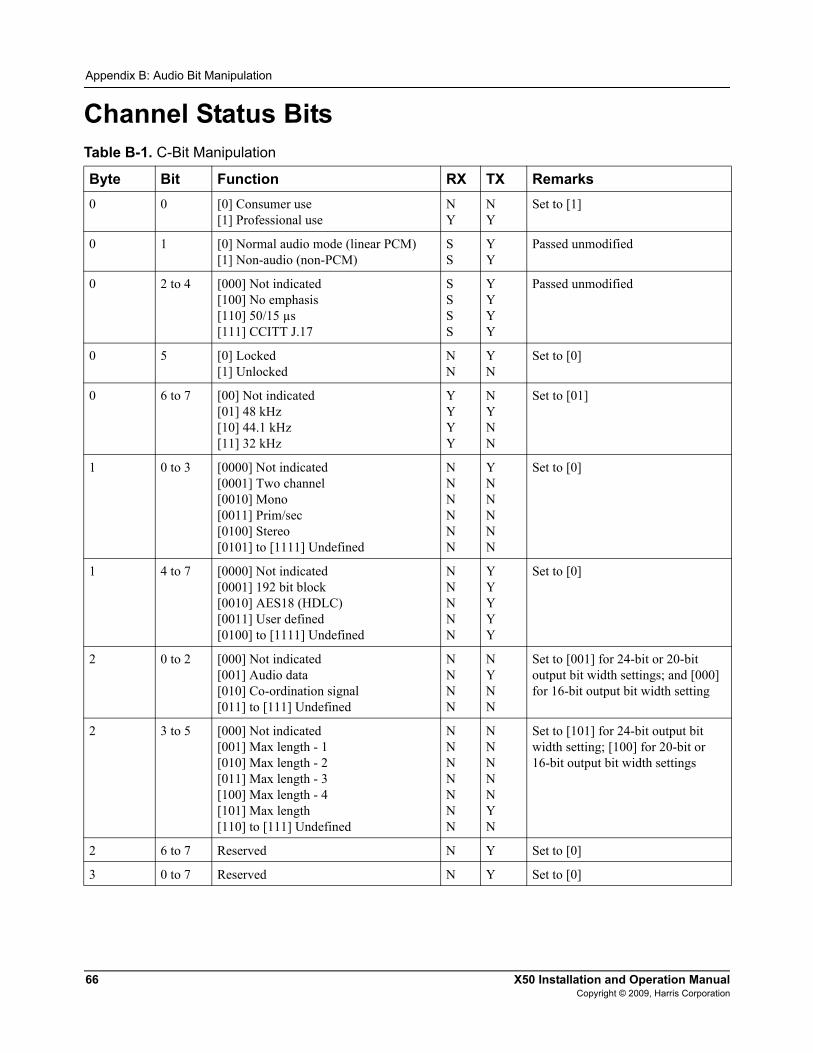
66 X50 Installation and Operation ManualCopyright © 2009, Harris Corporation
Appendix B: Audio Bit Manipulation
Channel Status BitsTable B-1. C-Bit Manipulation
Byte Bit Function RX TX Remarks0 0 [0] Consumer use
[1] Professional useNY
NY
Set to [1]
0 1 [0] Normal audio mode (linear PCM)[1] Non-audio (non-PCM)
SS
YY
Passed unmodified
0 2 to 4 [000] Not indicated[100] No emphasis[110] 50/15 µs[111] CCITT J.17
SSSS
YYYY
Passed unmodified
0 5 [0] Locked[1] Unlocked
NN
YN
Set to [0]
0 6 to 7 [00] Not indicated[01] 48 kHz[10] 44.1 kHz[11] 32 kHz
YYYY
NYNN
Set to [01]
1 0 to 3 [0000] Not indicated[0001] Two channel[0010] Mono[0011] Prim/sec[0100] Stereo[0101] to [1111] Undefined
NNNNNN
YNNNNN
Set to [0]
1 4 to 7 [0000] Not indicated[0001] 192 bit block[0010] AES18 (HDLC)[0011] User defined[0100] to [1111] Undefined
NNNNN
YYYYY
Set to [0]
2 0 to 2 [000] Not indicated[001] Audio data[010] Co-ordination signal[011] to [111] Undefined
NNNN
NYNN
Set to [001] for 24-bit or 20-bit output bit width settings; and [000] for 16-bit output bit width setting
2 3 to 5 [000] Not indicated[001] Max length - 1[010] Max length - 2[011] Max length - 3[100] Max length - 4[101] Max length[110] to [111] Undefined
NNNNNNN
NNNNNYN
Set to [101] for 24-bit output bit width setting; [100] for 20-bit or 16-bit output bit width settings
2 6 to 7 Reserved N Y Set to [0]
3 0 to 7 Reserved N Y Set to [0]
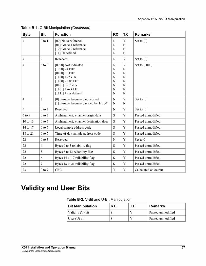
X50 Installation and Operation Manual 67Copyright © 2009, Harris Corporation
Appendix B: Audio Bit Manipulation
Validity and User Bits
4 0 to 1 [00] Not a reference [01] Grade 1 reference[10] Grade 2 reference[11] Undefined
NNNN
YNNN
Set to [0]
4 2 Reserved N Y Set to [0]
4 3 to 6 [0000] Not indicated[1000] 24 kHz[0100] 96 kHz[1100] 192 kHz[1100] 22.05 kHz[0101] 88.2 kHz[1101] 176.4 kHz[1111] User defined
NNNNNNNN
YNNNNNNN
Set to [0000]
4 7 [0] Sample frequency not scaled[1] Sample frequency scaled by 1/1.001
NN
YN
Set to [0]
5 0 to 7 Reserved N Y Set to [0]
6 to 9 0 to 7 Alphanumeric channel origin data S Y Passed unmodified
10 to 13 0 to 7 Alphanumeric channel destination data S Y Passed unmodified
14 to 17 0 to 7 Local sample address code S Y Passed unmodified
18 to 21 0 to 7 Time-of-day sample address code S Y Passed unmodified
22 0 to 3 Reserved N Y Set to 0
22 4 Bytes 0 to 5 reliability flag S Y Passed unmodified
22 5 Bytes 6 to 13 reliability flag S Y Passed unmodified
22 6 Bytes 14 to 17 reliability flag S Y Passed unmodified
22 7 Bytes 18 to 21 reliability flag S Y Passed unmodified
23 0 to 7 CRC Y Y Calculated on output
Table B-1. C-Bit Manipulation (Continued)
Byte Bit Function RX TX Remarks
Table B-2. V-Bit and U-Bit Manipulation
Bit Manipulation RX TX RemarksValidity (V) bit S Y Passed unmodified
User (U) bit S Y Passed unmodified

68 X50 Installation and Operation ManualCopyright © 2009, Harris Corporation
Appendix B: Audio Bit Manipulation
Miscellaneous DataTable B-3. Miscellaneous Data
Item RX Specification TX SpecificationAudio sampling frequency 32 to 48 kHz 48 kHz
Audio sampling word length 16 to 24 bits 24 bits

X50 Installation and Operation Manual 69Copyright © 2009, Harris Corporation
Index
KeywordsAActive Format Description (AFD) 33–42AES connector removal 3Analog audio jumpers 10–11Aspect ratio conversion 33–42Audio
metadata 48processing 47routing 49Status parameters 47
Australian TV closed captioning 43Auto Route feature 46
BBack and front views of the X50 4Backup input 46Baluns 12Black knee 43–45Bracket and relief bar installation 8–10Buttons 30Bypass function 47
CC-bit manipulation 66–67Closed captioning 43Color correction 43–45Control software, third-party 22–28Conversion specifications 51Correcting color 43–45
DDevice IP parameter 13Dimension and weight specifications 62Directives
Restriction on Hazardous Substances xWaste from Electrical and Electronic Equipment xi
Downloadable MIB files 22–28DVB teletext captioning 43
EElectrical and environmental requirements 7Embedding closed captioning 43Environmental requirements 7External baluns 12
FFree TV Australia closed captioning 43Front and back views of the X50 4
GGateway parameter 14
IInstallation preparation 7IP Address 13–25Ipconfig command 17
JJumpers 10–11
LLaser precautions 63–64LEDs 30Limitations of secondary channel 46Logos 46
MMain menu items 31Metadata, audio 48MIB file 22–28Mounting ears 8MS-DOS command prompt 17
70 X50 Installation and Operation ManualCopyright © 2009, Harris Corporation
Index
NNetwork settings 13–15
OOptions for the X50 3
PPacking list 5PC network settings 16–17Pinouts 4–5Power requirements 7Primary input 46Proc Bypass 47Product features 1–3Product servicing ixPushbutton controls 30
RRack mounting the X50 8–10Remote control 18–28Restriction on Hazardous Substances (RoHS) directive xReturning a product ixRevision history vii
SSafety
precautions xiiprecautions with lasers 63–64RoHS directive xWEEE directive xi
Secondary channel limitations 46Shipping a product ixSignal flow 6, 49SNMP 22–28Specifications
audio input 59component video 53, 58
composite video 53, 57conversion capability 51genlock 54GPI 61HDMI output 56LAN 61RS-422 61S-video 53, 57temperature 61video input 52–54video output 55–58weight and dimensions 62
Splash screen 46Subnet Mask 14Support bracket and relief bar installation 8–10Support documents viii
TTeletext system 43Temperature requirements 7Third-party control software 22–28
UUnpacking a product ix
VV-bit and U-bit manipulation 67Video Index (VI) 33–42
WWaste from Electrical and Electronic Equipment (WEEE)
directive xiWeb browser control 21Weight and dimensions specifications 62White Slope 43–44Wide Screen Signalling (WSS) 33–42World System Teletext 43


Broadcast Communications Division 4393 Digital Way | Mason, OH USA 45040 | Tel: 1 (513) 459 3400
www.broadcast.harris.com
Copyright © 2009 Harris Corporation
Harris and Leitch are registered trademarks of Harris Corporation. Trademarks and tradenames are the property of their respective companies.