Embed Size (px)
Citation preview

Web iSite User Guide iiDX Release 3.1

ii Web iSite User GuideiDX Release 3.1

Copyright © 2012 VT iDirect, Inc. All rights reserved. Reproduction in whole or in part without permission is prohibited. Information contained herein is subject to change without notice. The specifications and information regarding the products in this document are subject to change without notice. All statements, information, and recommendations in this document are believed to be accurate, but are presented without warranty of any kind, express, or implied. Users must take full responsibility for their application of any products. Trademarks, brand names and products mentioned in this document are the property of their respective owners. All such references are used strictly in an editorial fashion with no intent to convey any affiliation with the name or the product's rightful owner.
Document Name: UG_Web_iSite_User_Guide iDX 3.1_RevA_032712.pdf
Document Part Number: T0000431
Web iSite User Guide iiiiDX Release 3.1

Revision History
The following table shows all revisions for this document. If you do not have the latest revision for the release, or are not sure, please check the TAC Web site at: http://tac.idirect.net.
Revision Date Released Reason for Change(s) Who Updated?
A 03/20/2012 First release of document for iDX Release 3.1 CJones
Web iSite User Guide iviDX Release 3.1

Contents
List of Figures . . . . . . . . . . . . . . . . . . . . . . . . . . . . . . . . . . . . viii
List of Tables . . . . . . . . . . . . . . . . . . . . . . . . . . . . . . . . . . . . . . x
About This Guide . . . . . . . . . . . . . . . . . . . . . . . . . . . . . . . . . . . .xiPurpose. . . . . . . . . . . . . . . . . . . . . . . . . . . . . . . . . . . . . . . . . . . . . . . . . . . . . xi
Intended Audience . . . . . . . . . . . . . . . . . . . . . . . . . . . . . . . . . . . . . . . . . . . . . xi
Contents Of This Guide . . . . . . . . . . . . . . . . . . . . . . . . . . . . . . . . . . . . . . . . . . xi
Document Conventions . . . . . . . . . . . . . . . . . . . . . . . . . . . . . . . . . . . . . . . . . xii
Related Documents . . . . . . . . . . . . . . . . . . . . . . . . . . . . . . . . . . . . . . . . . . . . xiii
Getting Help . . . . . . . . . . . . . . . . . . . . . . . . . . . . . . . . . . . . . . . . . . . . . . . . xiii
1 Web iSite Overview . . . . . . . . . . . . . . . . . . . . . . . . . . . . . . . . . 11.1 Introduction . . . . . . . . . . . . . . . . . . . . . . . . . . . . . . . . . . . . . . . . . . . . . . 2
1.1.1 What You Can Do with Web iSite . . . . . . . . . . . . . . . . . . . . . . . . . . . . . . . . . . . 2Web iSite Highlights . . . . . . . . . . . . . . . . . . . . . . . . . . . . . . . . . . . . . . . . . . 2
1.1.2 Before Accessing the Evolution X1 Satellite Router . . . . . . . . . . . . . . . . . . . . . . . 2
1.2 Launching a Web iSite Session . . . . . . . . . . . . . . . . . . . . . . . . . . . . . . . . . . 3
1.3 Using the Web iSite Interface . . . . . . . . . . . . . . . . . . . . . . . . . . . . . . . . . . . 41.3.1 Web iSite User Interface Components . . . . . . . . . . . . . . . . . . . . . . . . . . . . . . . . 5
Browser Tab . . . . . . . . . . . . . . . . . . . . . . . . . . . . . . . . . . . . . . . . . . . . . . . 5Page . . . . . . . . . . . . . . . . . . . . . . . . . . . . . . . . . . . . . . . . . . . . . . . . . . . . 5Sections . . . . . . . . . . . . . . . . . . . . . . . . . . . . . . . . . . . . . . . . . . . . . . . . . . 6Information Fields . . . . . . . . . . . . . . . . . . . . . . . . . . . . . . . . . . . . . . . . . . . 6Top Navigation Bar . . . . . . . . . . . . . . . . . . . . . . . . . . . . . . . . . . . . . . . . . . . 6Main Default Pages . . . . . . . . . . . . . . . . . . . . . . . . . . . . . . . . . . . . . . . . . . . 7Sub-Pages . . . . . . . . . . . . . . . . . . . . . . . . . . . . . . . . . . . . . . . . . . . . . . . . . 7
v Web iSite User GuideiDX Release 3.1

Left Navigation Bar . . . . . . . . . . . . . . . . . . . . . . . . . . . . . . . . . . . . . . . . . . . 7X1 Satellite Router LED Indicators . . . . . . . . . . . . . . . . . . . . . . . . . . . . . . . . . 7Hiding and Un-hiding a Page Section . . . . . . . . . . . . . . . . . . . . . . . . . . . . . . . 9
2 The Dashboard . . . . . . . . . . . . . . . . . . . . . . . . . . . . . . . . . . . 112.1 Remote Information . . . . . . . . . . . . . . . . . . . . . . . . . . . . . . . . . . . . . . . . 12
2.2 Equipment Details . . . . . . . . . . . . . . . . . . . . . . . . . . . . . . . . . . . . . . . . . 12
2.3 Real-Time Remote Events . . . . . . . . . . . . . . . . . . . . . . . . . . . . . . . . . . . . 13Real-Time Event Messages . . . . . . . . . . . . . . . . . . . . . . . . . . . . . . . . . . . . . 13
3 Status Pages . . . . . . . . . . . . . . . . . . . . . . . . . . . . . . . . . . . . . 153.1 Modem Status Page . . . . . . . . . . . . . . . . . . . . . . . . . . . . . . . . . . . . . . . . . 16
3.1.1 Modem Information . . . . . . . . . . . . . . . . . . . . . . . . . . . . . . . . . . . . . . . . . . . . 163.1.2 Modem State . . . . . . . . . . . . . . . . . . . . . . . . . . . . . . . . . . . . . . . . . . . . . . . . 173.1.3 Rx State . . . . . . . . . . . . . . . . . . . . . . . . . . . . . . . . . . . . . . . . . . . . . . . . . . . 183.1.4 Tx State . . . . . . . . . . . . . . . . . . . . . . . . . . . . . . . . . . . . . . . . . . . . . . . . . . . 183.1.5 ODU Status . . . . . . . . . . . . . . . . . . . . . . . . . . . . . . . . . . . . . . . . . . . . . . . . . . 18
3.2 Ethernet Status Page . . . . . . . . . . . . . . . . . . . . . . . . . . . . . . . . . . . . . . . 193.2.1 Connection . . . . . . . . . . . . . . . . . . . . . . . . . . . . . . . . . . . . . . . . . . . . . . . . . 203.2.2 Transmitter . . . . . . . . . . . . . . . . . . . . . . . . . . . . . . . . . . . . . . . . . . . . . . . . . 203.2.3 Receiver . . . . . . . . . . . . . . . . . . . . . . . . . . . . . . . . . . . . . . . . . . . . . . . . . . . 21
3.3 IP Configuration Page . . . . . . . . . . . . . . . . . . . . . . . . . . . . . . . . . . . . . . . 213.3.1 LAN Interface . . . . . . . . . . . . . . . . . . . . . . . . . . . . . . . . . . . . . . . . . . . . . . . . 223.3.2 Management Interface . . . . . . . . . . . . . . . . . . . . . . . . . . . . . . . . . . . . . . . . . . 223.3.3 DHCP . . . . . . . . . . . . . . . . . . . . . . . . . . . . . . . . . . . . . . . . . . . . . . . . . . . . . 223.3.4 DNS . . . . . . . . . . . . . . . . . . . . . . . . . . . . . . . . . . . . . . . . . . . . . . . . . . . . . . 233.3.5 Static Routes . . . . . . . . . . . . . . . . . . . . . . . . . . . . . . . . . . . . . . . . . . . . . . . . 243.3.6 Multicast Groups . . . . . . . . . . . . . . . . . . . . . . . . . . . . . . . . . . . . . . . . . . . . . . 24
3.4 Remote Events Page . . . . . . . . . . . . . . . . . . . . . . . . . . . . . . . . . . . . . . . . 25
3.5 Satcom Graphs Page . . . . . . . . . . . . . . . . . . . . . . . . . . . . . . . . . . . . . . . . 263.5.1 Rx SNR . . . . . . . . . . . . . . . . . . . . . . . . . . . . . . . . . . . . . . . . . . . . . . . . . . . . 263.5.2 Tx Power . . . . . . . . . . . . . . . . . . . . . . . . . . . . . . . . . . . . . . . . . . . . . . . . . . . 273.5.3 Tx Frequency Offset . . . . . . . . . . . . . . . . . . . . . . . . . . . . . . . . . . . . . . . . . . . 273.5.4 Clock Adjustment . . . . . . . . . . . . . . . . . . . . . . . . . . . . . . . . . . . . . . . . . . . . . 28
4 Commissioning Pages . . . . . . . . . . . . . . . . . . . . . . . . . . . . . . . 294.1 Angle Calculator Page . . . . . . . . . . . . . . . . . . . . . . . . . . . . . . . . . . . . . . . 30
vi Web iSite User GuideiDX Release 3.1

4.1.1 Remote Location . . . . . . . . . . . . . . . . . . . . . . . . . . . . . . . . . . . . . . . . . . . . . . 304.1.2 Spacecraft Position . . . . . . . . . . . . . . . . . . . . . . . . . . . . . . . . . . . . . . . . . . . . 314.1.3 Elevation . . . . . . . . . . . . . . . . . . . . . . . . . . . . . . . . . . . . . . . . . . . . . . . . . . . 314.1.4 Gross Antenna Pointing . . . . . . . . . . . . . . . . . . . . . . . . . . . . . . . . . . . . . . . . . 31
4.2 Antenna Pointing Page . . . . . . . . . . . . . . . . . . . . . . . . . . . . . . . . . . . . . . 32
4.3 Cross Polarization Test Page . . . . . . . . . . . . . . . . . . . . . . . . . . . . . . . . . . 334.3.1 Transmit Frequency . . . . . . . . . . . . . . . . . . . . . . . . . . . . . . . . . . . . . . . . . . . . 334.3.2 Transmit Power . . . . . . . . . . . . . . . . . . . . . . . . . . . . . . . . . . . . . . . . . . . . . . 344.3.3 Modulator . . . . . . . . . . . . . . . . . . . . . . . . . . . . . . . . . . . . . . . . . . . . . . . . . . 35
5 Admin Pages. . . . . . . . . . . . . . . . . . . . . . . . . . . . . . . . . . . . . 375.1 File Management Page . . . . . . . . . . . . . . . . . . . . . . . . . . . . . . . . . . . . . . 38
5.1.1 Load Package . . . . . . . . . . . . . . . . . . . . . . . . . . . . . . . . . . . . . . . . . . . . . . . . 385.1.2 Load Options File . . . . . . . . . . . . . . . . . . . . . . . . . . . . . . . . . . . . . . . . . . . . . 39
5.2 The X1 Console Page . . . . . . . . . . . . . . . . . . . . . . . . . . . . . . . . . . . . . . . . 405.2.1 Using The Command Line . . . . . . . . . . . . . . . . . . . . . . . . . . . . . . . . . . . . . . . . 415.2.2 The X1 Event Message Window . . . . . . . . . . . . . . . . . . . . . . . . . . . . . . . . . . . . . 42
Event Message Format . . . . . . . . . . . . . . . . . . . . . . . . . . . . . . . . . . . . . . . . 42
Appendix A Restart X1 Satellite Router in Factory Default Mode . . 43A.1 Restarting the X1 Satellite Router in Factory Default Mode . . . . . . . . . . . . . 43
A.1.1 When to Use the Factory Default Mode . . . . . . . . . . . . . . . . . . . . . . . . . . . . . . . 43A.1.2 Operating in Factory Default Mode . . . . . . . . . . . . . . . . . . . . . . . . . . . . . . . . . . 44A.1.3 Factory Default Mode Restart Procedures . . . . . . . . . . . . . . . . . . . . . . . . . . . . . 44A.1.4 Returning to Normal Operational Mode . . . . . . . . . . . . . . . . . . . . . . . . . . . . . . . 45
Web iSite User Guide viiiDX Release 3.1

List of Figures
Figure 1. The Web iSite Login dialog . . . . . . . . . . . . . . . . . . . . . . . . . . . . . . . . . . . . . . 3Figure 2. Web iSite Default Page . . . . . . . . . . . . . . . . . . . . . . . . . . . . . . . . . . . . . . . . . 4Figure 3. Web iSite Browser Tab . . . . . . . . . . . . . . . . . . . . . . . . . . . . . . . . . . . . . . . . . 5Figure 4. Typical Web iSite Page . . . . . . . . . . . . . . . . . . . . . . . . . . . . . . . . . . . . . . . . . 5Figure 5. Management Interface Section of IP Configuration Page . . . . . . . . . . . . . . . . . . . 6Figure 6. Typical Section with IP Address and Subnet Mask Fields . . . . . . . . . . . . . . . . . . . 6Figure 7. Main Console Buttons . . . . . . . . . . . . . . . . . . . . . . . . . . . . . . . . . . . . . . . . . . 6Figure 8. Status Page Links . . . . . . . . . . . . . . . . . . . . . . . . . . . . . . . . . . . . . . . . . . . . . 7Figure 9. Commissioning Page Links . . . . . . . . . . . . . . . . . . . . . . . . . . . . . . . . . . . . . . . 7Figure 10. Admin Page Links . . . . . . . . . . . . . . . . . . . . . . . . . . . . . . . . . . . . . . . . . . . . 7Figure 11. Web iSite LED Indicators . . . . . . . . . . . . . . . . . . . . . . . . . . . . . . . . . . . . . . . 7Figure 12. Ethernet Status Page with Connection and Transmitter Sections hidden. . . . . . . . 9Figure 13. Page: Dashboard - Section: Remote Information . . . . . . . . . . . . . . . . . . . . . . . 12Figure 14. Page: Dashboard - Section: Equipment Details . . . . . . . . . . . . . . . . . . . . . . . . 12Figure 15. Page: Dashboard - Section: Real-Time Remote Events . . . . . . . . . . . . . . . . . . . 13Figure 16. Page: Modem Status - Section: Modem Information . . . . . . . . . . . . . . . . . . . . . 16Figure 17. Page: Modem Status - Section: Modem Information . . . . . . . . . . . . . . . . . . . . . 16Figure 18. Page: Modem Status - Section: Modem State . . . . . . . . . . . . . . . . . . . . . . . . . 17Figure 19. Page: Modem Status - Section: Rx State . . . . . . . . . . . . . . . . . . . . . . . . . . . . 18Figure 20. Page: Modem Status - Section: Tx State . . . . . . . . . . . . . . . . . . . . . . . . . . . . 18Figure 21. Page: Modem Status - Section: ODU Status . . . . . . . . . . . . . . . . . . . . . . . . . . 19Figure 22. Page: Ethernet Status with all sections collapsed . . . . . . . . . . . . . . . . . . . . . . 19Figure 23. Page: Ethernet Status - Section: Connection . . . . . . . . . . . . . . . . . . . . . . . . . 20Figure 24. Page: Ethernet Status - Section: Transmitter . . . . . . . . . . . . . . . . . . . . . . . . . 20Figure 25. Page: Ethernet Status - Section: Receiver . . . . . . . . . . . . . . . . . . . . . . . . . . . 21Figure 26. IP Configuration Page with all Sections collapsed . . . . . . . . . . . . . . . . . . . . . . 21Figure 27. Page: IP Configuration - Section: LAN Interface . . . . . . . . . . . . . . . . . . . . . . . 22Figure 28. Page: IP Configuration - Section: Management Interface . . . . . . . . . . . . . . . . . 22Figure 29. Page: IP Configuration - Section: DHCP Mode as Relay . . . . . . . . . . . . . . . . . . . 22Figure 30. Page: IP Configuration - Section: DHCP Mode as Server . . . . . . . . . . . . . . . . . . 23Figure 31. Page: IP Configuration Page - Section: DNS Mode as Enabled . . . . . . . . . . . . . . 23Figure 32. Page: IP Configuration Page - Section: Static Routes . . . . . . . . . . . . . . . . . . . . 24Figure 33. Page: IP Configuration Page - Section: Multicast Groups . . . . . . . . . . . . . . . . . 24Figure 34. Status Page Group: Real-Time Remote Events Page . . . . . . . . . . . . . . . . . . . . 25Figure 35. Satcom Graphs Page with all sections collapsed . . . . . . . . . . . . . . . . . . . . . . . 26Figure 36. Page: Satcom Graphs - Section: Receiver SNR . . . . . . . . . . . . . . . . . . . . . . . . 26Figure 37. Page: Satcom Graphs - Section: Tx Power . . . . . . . . . . . . . . . . . . . . . . . . . . . 27Figure 38. Page: Satcom Graphs - Section: Tx Frequency Offset . . . . . . . . . . . . . . . . . . . 27
viii Web iSite User GuideiDX Release 3.1

Figure 39. Page: Satcom Graphs - Section: Clock Adjustments . . . . . . . . . . . . . . . . . . . . 28Figure 40. Angle Calculator Page . . . . . . . . . . . . . . . . . . . . . . . . . . . . . . . . . . . . . . . . 30Figure 41. Page: Angle Calculator - Section: Remote Location . . . . . . . . . . . . . . . . . . . . . 30Figure 42. Page: Angle Calculator - Section: Spacecraft Position . . . . . . . . . . . . . . . . . . . 31Figure 43. Page: Angle Calculator - Section: Elevation . . . . . . . . . . . . . . . . . . . . . . . . . . 31Figure 44. Page: Angle Calculator - Section: Gross Antenna Pointing . . . . . . . . . . . . . . . . 31Figure 45. Antenna Pointing Page . . . . . . . . . . . . . . . . . . . . . . . . . . . . . . . . . . . . . . . 32Figure 46. Antenna Pointing Status . . . . . . . . . . . . . . . . . . . . . . . . . . . . . . . . . . . . . . 32Figure 47. Cross Polarization Test Page with all sections collapsed . . . . . . . . . . . . . . . . . 33Figure 48. Cross Polarization Page - Transmit Frequency Section . . . . . . . . . . . . . . . . . . . 33Figure 49. Cross Polarization Test Page - Start and Stop buttons . . . . . . . . . . . . . . . . . . . 34Figure 50. Cross Polarization Test Page - Transmit Power Section . . . . . . . . . . . . . . . . . . 34Figure 51. Cross Polarization Test Page - Modulator Section . . . . . . . . . . . . . . . . . . . . . . 35Figure 52. File Manage Page with all sections collapsed . . . . . . . . . . . . . . . . . . . . . . . . . 38Figure 53. The X1 Console Page . . . . . . . . . . . . . . . . . . . . . . . . . . . . . . . . . . . . . . . . . 41Figure 54. The X1 Command Line and Command Window . . . . . . . . . . . . . . . . . . . . . . . . 41Figure 55. The X1 Event Message Window . . . . . . . . . . . . . . . . . . . . . . . . . . . . . . . . . . 42
Web iSite User Guide ixiDX Release 3.1

x Web iSite User GuideiDX Release 3.1
List of Tables
Table 1. Description of X1 LED Indicators . . . . . . . . . . . . . . . . . . . . . . . . . . . . . . . . . . . . 8Table 2. Possible Values for Modem State Fields . . . . . . . . . . . . . . . . . . . . . . . . . . . . . . 17

About This Guide
PurposeThe Web iSite User Guide provides instructions for using the Web Interface to the iDirect Evolution X1 Satellite Routers. For details on configuring the X1 Satellite Routers, see the iBuilder User Guide; and for installing and commissioning the X1 Satellite Routers, see the iDirect Satellite Router Installation and Commissioning Guide, for iDX Release 3.1.
Intended AudienceThe Web iSite User Guide is intended for iDirect installers and other field installers and technicians tasked with installing and commissioning iDirect Evolution X1 Satellite Routers.
Contents Of This GuideThis document contains the following major sections:
• Web iSite Overview
• The Dashboard
• Status Pages
• Commissioning Pages
• Admin Pages
Web iSite User Guide xiiDX Release 3.1

Document ConventionsThis section illustrates and describes the standard conventions used throughout this document. Review the documentations conventions table prior to using this manual—it provides information on how to interpret standard conventions used in iDirect documents.
.
Convention Description Example
Blue Courier font
Used when the user is required to enter a command at a command line prompt or in a console)
[SWITCH_PORT_n]vid = vlan_id
Courier font
Used to show the resultant output from a command entered at a command line or on a console.
Output similar to the following sample appears:[SECURITY]password = $idi2$/bFMhf$5H8mYAaP1sTZ0m1Ny/dYyLaS40/admin_password = $idi2$146rgm$.KtDb4OH5CEBxzH6Ds2xM.ehHCHos_password = $1$UTKh0V$cc/UfNThFmBI7sT.zYptQ0
Bold Trebuchet
font
Used when the user must type information or values into a field in a Windows-type interface software.
Used when specifying names of commands, menus, folders, tabs, dialogs, list boxes, and options.
1.To add a remote to an inroute group, right-click the Inroute Group and select Add Remote.
The Remote dialog box has a number of user-selectable tabs across the top. The Information Tab is visible when the Dialog opens.
Blue Trebuchet
Used to show hyperlinked text within a document.
For instructions on performing specific tasks on a remote, see “Using the Remote Probe” on page 59.
Bold italic Trebuchet
Used to emphasize information for the user, such as in notes.
Note: The Tx Power for a remote cannot be set outside of the Min/Max range defined in iBuilder.
Red italic Trebuchet
font
Used when the user needs to STRICTLY follow instructions or have additional knowledge about a procedure or action.
WARNING!The following procedure may cause a network outage.
xii Web iSite User GuideiDX Release 3.1

Related DocumentsThe following iDirect documents are available at http://tac.idirect.net and may also contain information relevant to this release. Please consult these documents for information about installing and using iDirect’s satellite network software and equipment.
• iDX Release Notes
• iDX Software Installation Guide or Network Upgrade Procedure Guide
• iDX iMonitor User Guide
• iDX Technical Reference Guide
• iDX Installation and Commissioning Guide for Remote Satellite Routers
• iDX Features and Chassis Licensing Guide
• iDX Software Installation Checklist/Software Upgrade Survey
• iDX Link Budget Analysis Guide
Getting HelpThe iDirect Technical Assistance Center (TAC) is available to provide assistance 24 hours a day, 365 days a year. Software user guides, installation procedures, an FAQ page, and other documents that supports our products are available on the TAC Web site. The TAC Web site is accessed at: http://tac.idirect.net. The TAC may also be contacted by telephone or e-mail.
Telephone: (703) 648-8151.
E-mail: [email protected]
For sales or product purchasing information contact iDirect Corporate Sales at the following telephone number or e-mail address:
Telephone: (703) 648-8000
E-mail: [email protected]
iDirect strives to produce documentation that is technically accurate, easy to use, and helpful to our customers. Please help us to improve this document by providing any feedback. Send comments to [email protected].
Web iSite User Guide xiiiiDX Release 3.1

xiv Web iSite User GuideiDX Release 3.1

1 Web iSite Overview
This chapter presents an introduction of the Web iSite tool for working with iDirect Evolution X1 Satellite Routers. It contains a quick overview of what can be done with Web iSite, the various elements of which the user interface is comprised, and the basics of how to interact with the various pages of the Web iSite interface.
This chapter contains the following sections:
• “Introduction” on page 2
• “Launching a Web iSite Session” on page 3
• “Using the Web iSite Interface” on page 4
Web iSite User Guide 1iDX Release 3.1

Introduction
1.1 IntroductionThis introduction will describe what is possible with Web iSite, what must be done prior to accessing an Evolution X1 Satellite Router, and what is seen when Web iSite is first launched.
1.1.1 What You Can Do with Web iSiteThe X1 Web interface is used primarily for commissioning new sites and monitoring TDMA remotes from the local LAN side. It contains functions to help installers calculate antenna azimuth/elevation settings, perform antenna pointing, put up a continuous wave (CW) carrier for antenna peaking, cross-polarization and 1dB compression tests, and load software and configurations.
Web iSite also provides configuration and real-time status/statistical information about the X1 remote unit. Instead of interacting with the iDirect NMS, Web iSite connects directly to each remote to perform all of its operations—this access does not include historical data about the remote unit. See the Satellite Router Installation and Commissioning Guide for specific instructions on commissioning remotes.
Web iSite HighlightsA few highlights of Web iSite are listed below:
• Real-time display of the Satellite Router’s LED status
• A dashboard view of high-level remote information such as if the remote is in network, if it’s locked to the satellite, and real-time events
• Status and monitoring views of real-time modem information and events, Ethernet receive and transmit connections, and IP configuration and information
• Remote commissioning tools, including tools for lookup angle calculation, antenna pointing, and cross polarization
• Administration tools for loading new packages and options files
• Factory Default Mode restart to reset the Satellite Router to factory default settings
1.1.2 Before Accessing the Evolution X1 Satellite RouterWeb iSite may be used at any time to access the X1 Satellite Router. All that is required is the IP address assigned to the remote and a physical Ethernet connection to the remote.
The default IP address for an X1 remote unit is set to 192.168.0.1 when shipped from the factory or when booted into Factory Default Mode; otherwise the IP address is based on the iBuilder generated Options file that was last uploaded to the device. Connection to the X1 Satellite Router is not possible using the iVantage iSite Client.
Default factor setting of the Evolution X1 Satellite Router are as shown below:
• LAN IP address: 192.168.0.1
• Subnet Mask: 255.255.255.0
• DHCP Server: Enabled
• Single Client Address: 192.168.0.2
• Two Configured User Accounts: Admin and User (iDirect password)
2 Web iSite User GuideiDX Release 3.1

Launching a Web iSite Session
1.2 Launching a Web iSite SessionInternet Explorer, Google Chrome, or Firefox Internet browsers may be used to access an Evolution X1 Satellite Router. Web iSite compatible browser versions include:
• Internet Explorer (Version 7 and later)
• Mozilla Firefox (Version 8 and later)
• Google Chrome (Version 16 and later)
When initially opened, Web iSite the X1 Satellite Router already has two default user accounts: admin and user. The admin user has access to the full functionality of Web iSite, while the user account has restricted access.
By default, the admin and user accounts both have the same “iDirect” password. These accounts and passwords may be configured later using the NMS iBuilder application. For information on configuring remotes, see the iBuilder User Guide.
To launch Web iSite perform the following:
1. Connect the LAN port of the PC to the LAN port of the Satellite Router using an Ethernet cable.
2. Launch the Web browser of choice.
3. Enter the IP Address of the X1 Satellite Router into the url address field, as shown in the following example, where nnn.nnn.nnn.nnn is the IP Address of the X1 remote:
http://196.168.0.1 (the default IP address is shown here)
Note: If a connection is not established using the default IP address then the IP Address from the Options file must be used. Also see Appendix A.
4. Enter a User name and Password when the Login page displays. On the initial login, enter the default name of admin and the password of iDirect.
Figure 1. The Web iSite Login dialog
5. Click Login to complete the login process.
The Web iSite application automatically connects to the X1 Satellite Router and the CPU processes that perform the Web iSite functions.
Web iSite User Guide 3iDX Release 3.1

Using the Web iSite Interface
1.3 Using the Web iSite InterfaceThe default page of Web iSite is shown in Figure 2. This page, including the visible page elements, is typical of the pages of which Web iSite is comprised. These elements are described in the following discussions.
Figure 2. Web iSite Default Page
4 Web iSite User GuideiDX Release 3.1

Using the Web iSite Interface
1.3.1 Web iSite User Interface ComponentsWeb iSite consists of several pages, each comprised of one or more sections that contain various page elements. These page elements are described in the following sections.
Browser TabAfter connecting to the Evolution X1 Satellite Router, the browser tab appears as shown in Figure 3. The tab identifies the name of the Web iSite application, and the IP address of the X1 remote to which the connection is established. The browser tab may appear slightly different, based on the Internet browser.
Figure 3. Web iSite Browser Tab
PageAny screen presented in Web iSite, is referred to as a page. The entire application is comprised of several pages that either presents X1 information or supports interaction with the Satellite Router. The contents of a page may provide static or real-time information about the remote. A page may also provide interactive tools that supports a Web iSite operation.
Figure 4. Typical Web iSite Page
Web iSite User Guide 5iDX Release 3.1

Using the Web iSite Interface
SectionsThe information on a Web iSite page is generally grouped by section. Each page is normally partitioned into two or more sections. A section contains a grouping of information fields, or elements used in performing an operation—such as file uploading or putting up a continuous carrier wave (CW). Each section is identified by a section title that reflects the specific information grouping. Figure 5, shows the Management Interface section of the IP Configuration page.
Figure 5. Management Interface Section of IP Configuration Page
Information FieldsEach data element presented in a page section is contained in an information field. Most sections contain a grouping of static or dynamic information fields. A page section generally consists of several fields, each of which is identified by a field label that indicates the field content. Some data fields may not be modified and are only for viewing or monitoring purposes; the data in other fields may be modified.
Figure 6. Typical Section with IP Address and Subnet Mask Fields
Top Navigation BarAcross the top of each Web iSite page is the top navigation bar. This navigation bar has four main page buttons that appear on each Web iSite page. When one of these buttons is clicked, the associated page group may be accessed. Clicking the Commissioning button, for example, navigates to the Commissioning pages. Likewise, clicking the Admin navigates to the Admin page group.
Figure 7. Main Console Buttons
6 Web iSite User GuideiDX Release 3.1

Using the Web iSite Interface
Main Default PagesTo work with one of the main page groups of Web iSite, simply click on one of the main page buttons. When one of these buttons is clicked the default page for the selected page group opens. For example, the default page for the Status group, is the Modem Status page; the default page for the Commissioning page group is the Angle Calculator page; and the default page for the Admin group is the File Management page.
Sub-PagesEach Web iSite page group is comprised of a number of pages that displays different content. The pages of the group may be accessed from the default page of a group as well as from the other pages of the group. The pages of a page group are called sub-pages. The Console Page, for example is a sub-page of the Admin page group.
Left Navigation BarAlong the left side of each Web iSite page is the left navigation bar. This panel contains links to additional Web iSite pages in the current page group, which may be accessed from the current page. The left navigation bar and the associated page links are displayed on each page of the page group. Click on the page link to navigate to the selected page.
X1 Satellite Router LED IndicatorsWhen a connection with an X1 Satellite Router is established, the real-time status of each LED indicator of that Satellite Router is reflected on each Web iSite page. A description of each of the indicators, shown in Figure 11, is provided in Table 1.
Figure 11. Web iSite LED Indicators
Figure 8. Status Page Links Figure 9. Commissioning Page Links
Figure 10. Admin Page Links
Web iSite User Guide 7iDX Release 3.1

Using the Web iSite Interface
Note: Table abbreviations include the following: Demod = Demodulator; NCR = Network Clock Reference; D/S = Downstream
Table 1. Description of X1 LED Indicators
LED LED State Description of X1 State
RX
OFF Receiver disabled or not configured.
Yellow—Solid On D/S carrier configured, but demodulator is not locked.
Yellow—1 Sec Flashing Downstream carrier configured, demodulator locked to downstream carrier, but NCR not locked.
Green—Solid On D/S carrier configured—Demod/NCR locked to D/S Carrier.
TX
OFF Modem OFF (Rx only Mode)
Yellow—Solid On Transmitter disabled)
Green—Solid On Transmitter enabled
NET
Red—Solid Serious fault indicated when RX and NET LEDs are also red.
Yellow—Solid On Demodulator Not Locked to downstream carrier
Yellow—1 Sec Flashing Demodulator locked to downstream carrier
Green—2 Sec Flashing Primary D/S carrier locked——acquisition in progress
Green—1 Sec Flashing Demodulator/NCR locked to D/S carrier—acquisition in progress
Green—Solid Modem acquired into network
POWER
OFF Board DC power Input low or not present at the X1 remote.
Green—Solid Board DC power Input threshold detected
Yellow—Solid BUC/LNB power failure.
8 Web iSite User GuideiDX Release 3.1

Using the Web iSite Interface
Hiding and Un-hiding a Page SectionIn Web iSite, it is possible hide any page section that does not need to be viewed. With a single click on a section title—for example, Receiver, the information fields of that section are hidden. To un-hide or display the fields of the section, click Receiver a second time. The contents of a section toggles between display and hide with each click of the section title. When hidden, the section contracts, showing only the section title. In Figure 12, for example, the Connection and Transmitter sections are hidden.
Figure 12. Ethernet Status Page with Connection and Transmitter Sections hidden.
Web iSite User Guide 9iDX Release 3.1

Using the Web iSite Interface
10 Web iSite User GuideiDX Release 3.1

2 The Dashboard
This chapter describes the X1 Dashboard. The Dashboard page provides a quick overview of key information about the X1 Satellite Router to which the connection is established.
The Dashboard is the default landing page—displayed whenever Web iSite is launched. From the Dashboard, access is provided to basic information such as the remote’s IP Address, whether the remote is in network, if it’s locked to the satellite, as well as a view of real-time remote events.
This chapter contains the following sections:
• “Remote Information” on page 12
• “Equipment Details” on page 12
• “Real-Time Remote Events” on page 13
Note: Since the Dashboard is a central point for viewing the modem’s key identifiers, operating parameters, and real-time events, information seen on the Dashboard may also be seen on another of the Web iSite pages.
Web iSite User Guide 11iDX Release 3.1

Remote Information
2.1 Remote InformationFigure 13 shows the Remote Information section of the Web iSite Dashboard page. This section provides key identifier information for the X1 Satellite Router. For example the Model Type, which may be and Evolution X1 Indoor or Evolution X1 Outdoor unit; the device Serial Number, found on the back panel of the device; the Login Name of the current Web iSite session; the Software Version, which identifies the version number and build that is currently in operation on the remote; and the remote’s LAN IP Address and LAN Subnet Mask.
Figure 13. Page: Dashboard - Section: Remote Information
2.2 Equipment DetailsThe Equipment Details section of the Web iSite Dashboard page is shown in Figure 14. This section of the dashboard provides important real-time information as to the status of the remote in terms of the network—for example whether the remote’s Data Link is established or otherwise; whether the remote is currently In Network, Waiting for Rx Lock, Waiting for Acquisition, or otherwise.
Other equipment details include real-time status of the key modem operating parameters of Tx Power, the modems maximum transmit power determined during commissioning; the remote’s operating Temperature, and the remote’s total Up Time.
Figure 14. Page: Dashboard - Section: Equipment Details
12 Web iSite User GuideiDX Release 3.1

Real-Time Remote Events
2.3 Real-Time Remote EventsFigure 15, shows the Real-Time Remote Events section of the Web iSite Dashboard. After the software and options file has been loaded to the X1 Satellite Router and the modem is reset and restarted, Web iSite displays the last 10 events that have occurred on the remote.
This Dashboard section, the same as in the Web iSite Status pages, is primarily a monitoring tool used to aid in resolving issues that may exist with the remote. With the information provided in this window, an iDirect TAC representative can trace events in the remote and perform an investigation and analysis of problems that may occur in the remote.
Figure 15. Page: Dashboard - Section: Real-Time Remote Events
Real-Time Event MessagesTypical real-time remote event messages that may be seen on the Dashboard include items such as TCP connection assigned or terminated; TX power setting; flash firmware completed; modem configuration written; or Remote Hello, upon being reset. In general, Dashboard real-time remote events include the following:
• REMOTE HELLO—generated on first acquisition into the network after reset
• TLS client connection/disconnection
• Package and options upload
• CrossPolTestMsg
• PanicMsg
• ResetMsg
• RxODUMsg
• TxODUMsg
• StopTxMsg
• TxPowerMsg
Web iSite User Guide 13iDX Release 3.1

Real-Time Remote Events
14 Web iSite User GuideiDX Release 3.1

3 Status Pages
This chapter describes the Web iSite Status pages. This page group provides a monitoring window into the real-time events of the X1 Satellite Router. The Status pages provides a view of some of the key operating parameters of the Satellite Router and access to graphic visuals of the Satellite Router’s network satellite traffic.
This chapter contains the following sections:
• “Modem Status Page” on page 16
• “Ethernet Status Page” on page 19
• “IP Configuration Page” on page 21
• “Remote Events Page” on page 25
• “Satcom Graphs Page” on page 26
Web iSite User Guide 15iDX Release 3.1

Modem Status Page
3.1 Modem Status PageThe Modem Status page is the default page of the Status page group of Web iSite. This page provides specific modem information and operating parameters of the X1 Satellite Router. The Modem Status page, as shown in Figure 16, is comprised of the sections Modem Information, Modem State, Rx State, Tx State, and ODU Status.
Figure 16. Page: Modem Status - Section: Modem Information
3.1.1 Modem InformationFigure 17 shows the Modem Information section of the Modem Status page. This section provides key identifier information for the X1 Satellite Router. For example the Model Type, which may be an EvolutionX1Indoor or EvolutionX1Outdoor unit; the device Serial Number, found on the back panel of the device; the Satellite Router’s Ethernet MAC Address; and the Software Version, which identifies the version number and build that is currently in operation on the remote.
Figure 17. Page: Modem Status - Section: Modem Information
16 Web iSite User GuideiDX Release 3.1

Modem Status Page
3.1.2 Modem StateFigure 18 shows the Modem State section of the Modem Status page. This section provides information relative to the modem’s status with regard to the network, as well specific modem operating parameters. The CPU Load reflects the current operating load of the remote’s CPU; and the Temperature reflects the remote’s current board temperature. Table 2 show possible values for the Network, Data Link, Satellite Rx, and Satellite Tx fields.
Figure 18. Page: Modem Status - Section: Modem State
Table 2 show possible values for the Network, Data Link, Satellite Rx, and Satellite Tx fields.
Table 2. Possible Values for Modem State Fields
Network Data Link Satellite Rx Satellite Tx
Waiting for Rx Lock Closed Waiting for Tuner Lock On
Waiting for Acquisition Opening Waiting for Demod Lock Off
In Acquisition Established Waiting for NCR Lock
Detected Pass-Through Locked
In Network Closing
Wrong Network Rx-Only
Web iSite User Guide 17iDX Release 3.1

Modem Status Page
3.1.3 Rx StateThe Rx State section reflects the modem’s receive operating parameters. iBuilder configured values contained in this section include the Downlink Center Frequency and Symbol Rate, both of which should reflect the corresponding values contained in the modem’s Options file. Dynamic values of this section include the remote’s Rx Composite Power, which changes as it reflects the fluctuating characteristics of the Rx SNR; and the CRC 8 and CRC 32 fields, which show the receive line frame errors for 8-bit and 32-bit CRC calculations.
Figure 19. Page: Modem Status - Section: Rx State
3.1.4 Tx StateThe Tx State section reflects the modem’s transmit operating parameters. The values shown in the Tx Power, Max TX Power, and Initial Tx Power fields should reflect the corresponding values derived during commissioning, configured in iBuilder and reflected in the modem’s Options file.
Figure 20. Page: Modem Status - Section: Tx State
3.1.5 ODU StatusThe ODU (outdoor unit) Status section reflects key operating parameters of the Block Up Converter (BUC) and the Low Noise Block (LNB) amplifier devices that are associated with the Satellite Router.
Displayed in this section include the iBuilder configured settings for the LNB Local Oscillator Frequency and the BUC Local Oscillator Frequency translation values; the operating L-Band Frequency setting; and the LNB Spectral Inversion and BUC Spectral Inversion fields, both of which may show a configured value of Normal or Inverted.
18 Web iSite User GuideiDX Release 3.1

Ethernet Status Page
Figure 21. Page: Modem Status - Section: ODU Status
3.2 Ethernet Status PageThe Ethernet Status page, as the name implies, provides pertinent information about the Satellite Router’s Ethernet connection, its receive data link, and its transmit data link. This information is presented in the Connection, Transmitter, and Receiver sections, as shown in Figure 22, and described in the following sections.
Figure 22. Page: Ethernet Status with all sections collapsed
Web iSite User Guide 19iDX Release 3.1

Ethernet Status Page
3.2.1 ConnectionFigure 23, shows the Connection section of the Ethernet Status page. This section provides key Ethernet connection information for the local LAN subnet to which the X1 Satellite Router is connected—for example connection Speed, Duplex Mode, the IP Address, MAC Address, and the Subnet Mask.
The Status field displays either Connected or Disconnected based on the actual connection status of the Satellite Router. If the modem is connected, the Speed field shows the connections speed established at 10 Mbit/s or 100 Mbit/s; otherwise the field will contain Not Available. Possible values for the Duplex Mode field include Full Duplex, Half Duplex, and Not Available.
Figure 23. Page: Ethernet Status - Section: Connection
3.2.2 TransmitterFigure 24 shows the Transmitter section of the Ethernet Status page. This section tracks and displays the total number of Ethernet Frames transmitted by the Satellite Router, the number of Dropped Frames, and the number of Error Frames, seen by the Satellite Router, since the modem was last restarted. This statistical information provides a key measure of the stability of the remote’s Ethernet transmit characteristics.
Figure 24. Page: Ethernet Status - Section: Transmitter
20 Web iSite User GuideiDX Release 3.1

IP Configuration Page
3.2.3 ReceiverThe Receiver section of the Ethernet Status page is shown in Figure 25. This section tracks and displays the total number of Ethernet Frames received by the Satellite Router, the number of Dropped Frames, and the number of Error Frames, since the modem was last restarted. This statistical information provides a key measure of the stability of the remote’s Ethernet receive characteristics.
Figure 25. Page: Ethernet Status - Section: Receiver
3.3 IP Configuration PageThe IP Configuration page, provides important configuration information about the network in which the Satellite Router is connected. This information, which reflects data contained in the configuration database, is presented in the LAN Interface, Management Interface, DHCP, Static Routes, and Multicast Group sections, as shown in Figure 26. The sections of this page are all shown hidden.
Figure 26. IP Configuration Page with all Sections collapsed
By design, the X1 Satellite Router may be configured on up to four VLANs - by default, VLAN1 is defined as the Management VLAN; the other three are considered User VLANs. The IP Configuration page shown in Figure 26, indicates that only the default VLAN - the Management VLAN is configured. When additional VLANs are configured, each has a unique VLAN tab — the additional tabs are numbered using the VLAN ID —for example VLAN1, VLAN12, VLAN22, and VLA32. Only the default VLAN has the Management Interface section. These sections are described in the following discussions.
Web iSite User Guide 21iDX Release 3.1

IP Configuration Page
3.3.1 LAN InterfaceFigure 27 shows the LAN Interface of the IP Configuration page. In an iDirect Network, the LAN Interface refers to the IP address through which the remote communicates with the LAN network behind the Satellite Router. Hence, the LAN Interface IP Address represents the remote’s IP Address on the VLAN on which it is configured; the associated subnet mask is shown in the Netmask field.
Figure 27. Page: IP Configuration - Section: LAN Interface
3.3.2 Management InterfaceFigure 28 shows the Management Interface of the IP Configuration page. In an iDirect network, the Management Interface refers to the hub side of the network. Hence, the remote’s Management Interface IP Address represents the remote’s virtual interface on the default VLAN. The NMS always communicates with the remotes using this IP address. This address should not conflict with the LAN Interface addresses.
Figure 28. Page: IP Configuration - Section: Management Interface
3.3.3 DHCPThe DHCP section of the IP Configuration page displays as shown in Figure 29, when the DHCP Mode in iBuilder is ‘set to Relay. The DHCP mode is configured for Relay when an existing or separate DHCP server is used at the hub location. In this mode only the IP Address of the relay station is shown, in the Relay To field. In iBuilder, DHCP mode is disabled by default.
Figure 29. Page: IP Configuration - Section: DHCP Mode as Relay
22 Web iSite User GuideiDX Release 3.1

IP Configuration Page
The DHCP section is extended, as shown in Figure 30, when the DHCP Mode is configured for Server. The DHCP Mode is selected as Server if the X1 remote is enabled to act as the DHCP Server. In this case, the section is extended to show the Lease Range and Lease Time; the IP addresses for both the Primary and Secondary DNS; and for the Default Gateway.
Figure 30. Page: IP Configuration - Section: DHCP Mode as Server
3.3.4 DNSThe DNS section of the IP Config page, is shown in Figure 31. Here, the section is extended to show the Name and IP Address for both the Primary and Secondary DNS. If the DNS Mode value is Disabled, the section only shows the DNS Mode field—no other fields are shown.
Figure 31. Page: IP Configuration Page - Section: DNS Mode as Enabled
Web iSite User Guide 23iDX Release 3.1

IP Configuration Page
3.3.5 Static RoutesFigure 32 shows the Static Routes section of the IP Configuration page. This page section displays the list of IP Addresses configured in iBuilder as Static Routes for the X1 Satellite Router.
Figure 32. Page: IP Configuration Page - Section: Static Routes
3.3.6 Multicast GroupsThe Multicast Groups section of the IP Configuration page is shown in Figure 33. Using the Direction to indicate the flow of traffic, and the IP Address of the multicast group, this section lists the persistent Multicast Groups in which the X1 Satellite Router is a member.
Figure 33. Page: IP Configuration Page - Section: Multicast Groups
24 Web iSite User GuideiDX Release 3.1

Remote Events Page
3.4 Remote Events PageThe X1 Real Time Remote Events page is shown in Figure 34. When the remote is in operation, this page logs the events of the X1 Satellite Router, displaying the last 40 events that have occurred.
This area, is also a monitoring and troubleshooting tool that is used to aid in resolving problems that may exist with the remote. With the information provided in this window, an iDirect TAC representative can perform an investigation and analysis of problems with the remote and quickly pinpoint problems.
Figure 34. Status Page Group: Real-Time Remote Events Page
Web iSite User Guide 25iDX Release 3.1
Satcom Graphs Page
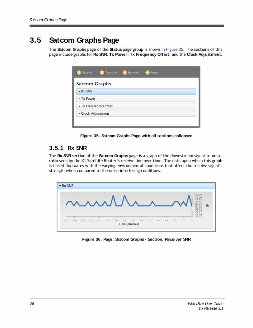
3.5 Satcom Graphs PageThe Satcom Graphs page of the Status page group is shown in Figure 35. The sections of this page include graphs for Rx SNR, Tx Power, Tx Frequency Offset, and the Clock Adjustment.
Figure 35. Satcom Graphs Page with all sections collapsed
3.5.1 Rx SNRThe Rx SNR section of the Satcom Graphs page is a graph of the downstream signal-to-noise ratio seen by the X1 Satellite Router’s receive line over time. The data upon which this graph is based fluctuates with the varying environmental conditions that affect the receive signal’s strength when compared to the noise interfering conditions.
Figure 36. Page: Satcom Graphs - Section: Receiver SNR
26 Web iSite User GuideiDX Release 3.1

Satcom Graphs Page
3.5.2 Tx PowerThe Tx Power section of the Satcom Graphs page is a graph of the X1 Satellite Router’s transmit line power characteristics over time.
Figure 37. Page: Satcom Graphs - Section: Tx Power
3.5.3 Tx Frequency OffsetThe Tx Frequency Offset section of the Satcom Graphs page is a graph of the X1 Satellite Router’s transmit line frequency offset characteristics over time. The Tx frequency offset data reflects the frequency offsets applied to the remote from the Protocol Processor as part of the uplink control process (UCP).
Figure 38. Page: Satcom Graphs - Section: Tx Frequency Offset
Web iSite User Guide 27iDX Release 3.1
Satcom Graphs Page
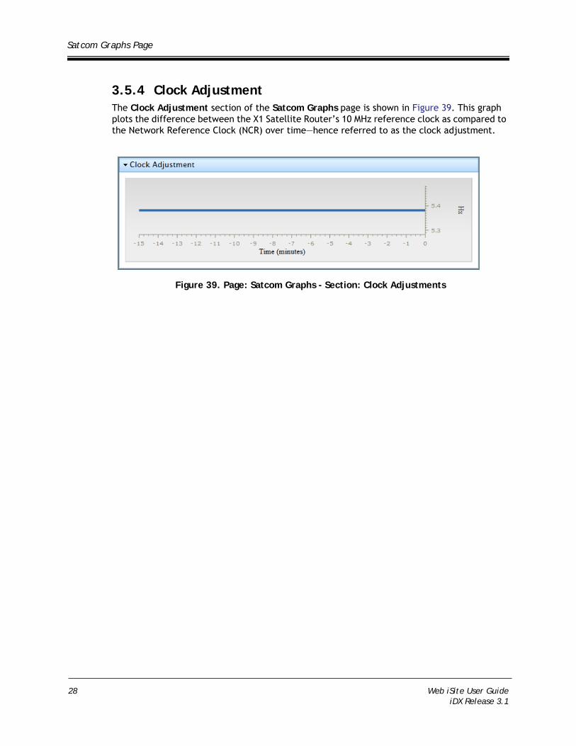
3.5.4 Clock AdjustmentThe Clock Adjustment section of the Satcom Graphs page is shown in Figure 39. This graph plots the difference between the X1 Satellite Router’s 10 MHz reference clock as compared to the Network Reference Clock (NCR) over time—hence referred to as the clock adjustment.
Figure 39. Page: Satcom Graphs - Section: Clock Adjustments
28 Web iSite User GuideiDX Release 3.1

4 Commissioning Pages
This chapter presents the Web iSite Commissioning pages. The pages of this page group, which may be familiar to users of the iVantage iSite tool, are designed to assist network installers and technicians in working with the X1 Satellite Routers during the installation and commissioning tasks. Access to the Commissioning pages is limited to Admin users only.
This chapter contains the following sections:
• “Angle Calculator Page” on page 30
• “Antenna Pointing Page” on page 32
• “Cross Polarization Test Page” on page 33
Note: This chapter only describes the various pages of this page group, and the tools found on these pages. For full information and specific details on installing and commissioning the Evolution X1 Satellite Routers, refer to the iDirect Satellite Routers Installation and Commissioning Guide.
Web iSite User Guide 29iDX Release 3.1

Angle Calculator Page
4.1 Angle Calculator PageThe Web iSite Angle Calculator page, shown in Figure 40, is a Web iSite tool designed to assist with gross antenna pointing. Given the appropriate values, the look angle calculator determines the Polarization Offset, Azimuth True, and Elevation Actual.
Notice that with some fields, increment and decrement buttons are adjacent to the field, so that adjust to the field value may be made as necessary. There are also fields that have an adjacent drop arrow so that the appropriate value may be selected from a list—for example, Deg. North or Deg. West. The page fields that are white spaces are display only fields.
If this is an initial installation of the Satellite Router, the modifiable fields are populated with values from the remote’s Options file or will have an initial value of 0.0. All other fields will be blank.
Figure 40. Angle Calculator Page
4.1.1 Remote LocationThe Remote Location section of the Angle Calculator page is shown in Figure 41. This section is used to enter the Latitude and Longitude for the X1 Satellite Router’ exact location.
Figure 41. Page: Angle Calculator - Section: Remote Location
30 Web iSite User GuideiDX Release 3.1

Angle Calculator Page
4.1.2 Spacecraft PositionThe Spacecraft Position section of the Angle Calculator page is shown in Figure 42. Here, the Longitude is entered for the satellite that is being used. Use the drop arrow to select the appropriate direction of the satellite as Deg. East or Deg. West.
Figure 42. Page: Angle Calculator - Section: Spacecraft Position
4.1.3 ElevationThe Elevation section of the Angle Calculator page is shown in Figure 43. Here, the an Elevation Offset is entered in order to derive the correct value for Elevation True.
Figure 43. Page: Angle Calculator - Section: Elevation
4.1.4 Gross Antenna PointingThe Gross Antenna Pointing section of the Angle Calculator page is shown in Figure 44. The look angle calculated values for Elevation Actual, Azimuth True, and Polarization Offset are displayed in this section.
Figure 44. Page: Angle Calculator - Section: Gross Antenna Pointing
Web iSite User Guide 31iDX Release 3.1

Antenna Pointing Page
4.2 Antenna Pointing PageThe Web iSite Antenna Pointing page, shown in Figure 45, is a Web iSite tool designed to assist with antenna pointing. The tool itself is a color-coded graphical voltage display that simplifies the task of locking on to the downstream carrier for a specific network.
Figure 45. Antenna Pointing Page
As the antenna azimuth plane is manipulated in a slow sweeping motion, the graph displays a voltage reading in the range of 12-24 volts to indicate the signal strength and when the remote is successfully locked onto the correct satellite and outbound carrier.
The antenna status may be determined using the information given in Figure 46. The graphical display of the voltage range is color-coded, where 0-2 VDC is red; 2-10 VDC is yellow; and 12-24 VDC is green. As the antenna azimuth is moved, the graph will turn red, then yellow, and finally completely green as there is a lock on to the downstream carrier.
Figure 46. Antenna Pointing Status
Note: For full information and specific details on installing and commissioning the Evolution X1 Satellite Routers, refer to the iDirect Satellite Routers Installation and Commissioning Guide.
32 Web iSite User GuideiDX Release 3.1

Cross Polarization Test Page
4.3 Cross Polarization Test PageThe Web iSite Cross Polarization Test page is shown in Figure 47. This test page supports the putting up of a modulated or unmodulated continuous wave (CW) carrier as part of the test. The three sections of this page include Transmit Frequency, Transmit Power, and Modulator. The cross polarization test is generally performed in conjunction with the Satellite Provider.
Figure 47. Cross Polarization Test Page with all sections collapsed
Note: As mentioned earlier, refer to the Satellite Router Installation and Commissioning Guide, for complete instructions on commissioning the X1 Satellite Router—including the performance of the Cross Polarization Test.
4.3.1 Transmit FrequencyFigure 48 shows the Transmit Frequency section of the Cross Polarization page. The fields in this section provide the setup for the cross-polarization test. The test frequency, the value entered for RF Uplink Frequency, is obtained from the satellite provider. The BUC LO (local oscillator) Frequency, which is generally read from the remote’s Options file, should reflect the appropriate value associated with Ku-Band, Ka-Band, or C-Band. The L-Band Tx Frequency is automatically calculated and displayed for the X1 Satellite Router.
Figure 48. Cross Polarization Page - Transmit Frequency Section
Web iSite User Guide 33iDX Release 3.1

Cross Polarization Test Page
In the Transmit Frequency section of the Cross Polarization Test page, the RF Uplink Frequency, BUC LO Frequency, and L-Band TX Frequency field values should fall within the following ranges:
RF Uplink Frequency — 5,850 MHz to 14,750 MHz
BUC LO Frequency — 4,900 MHz to 13,050 MHz
L-Band TX Frequency — 950 MHz to 1,700 MHz
If a field value exceeds the expected range, a red exclamation mark appears beside the field.
As part of the cross polarization test the operator is instructed by the Satellite Provider’s Operator to put up the carrier wave (CW), at the frequency that was entered in the RF Uplink Frequency field. When instructed, simply click the Start button shown in Figure 49. At any time or when instructed, click the Stop button to take down the CW carrier.
Figure 49. Cross Polarization Test Page - Start and Stop buttons
As long as the L-Band TX Frequency is within range, the Start button will be enabled and a Cross Polarization Test can be started.
4.3.2 Transmit PowerFigure 50 shows the Transmit Power section of the Cross Polarization page. The Adjust Transmit Power field is used in performing the 1 db compression test, while the Network Operator continues to monitor the Carrier Wave (CW). The value, which is generally incremented in 1 db adjustments under the advice of the satellite provider’s operator, may only be adjusted after the test is started. The transmit power adjustment value may also be adjusted downward if the BUC is already saturated and the 1 db adjustment shows no further increase in power.
Figure 50. Cross Polarization Test Page - Transmit Power Section
34 Web iSite User GuideiDX Release 3.1

Cross Polarization Test Page
4.3.3 ModulatorFigure 51 shows the Modulator section of the Cross Polarization page. The cross polarization test supports the testing of a remote by transmitting either a modulated or unmodulated carrier at a specific uplink frequency. Using this section, and the Modulator PN radio buttons, an installer can control the ON and OFF switching of the CW carrier. The modulation should only be switched On after receiving instruction to do so by the Satellite Provider operator.
Figure 51. Cross Polarization Test Page - Modulator Section
Web iSite User Guide 35iDX Release 3.1

Cross Polarization Test Page
36 Web iSite User GuideiDX Release 3.1
5 Admin Pages
This chapter describes the Web iSite Admin pages. This page group provides additional tools for assisting installers or technicians with the task of troubleshooting or commissioning of the remote. Tools are included for loading the software Package and Options file to the X1 Satellite Router, as well as a command console tool for invoking a limited set of commands on the X1 remote.
Access to the Admin page group is available only to Admin users.
This chapter contains the following sections:
• “File Management Page” on page 38
• “The X1 Console Page” on page 40
Web iSite User Guide 37iDX Release 3.1

File Management Page
5.1 File Management PageThe File Management page, shown in Figure 52, is generally used at the Satellite Router location, during a commissioning phase, to load the necessary files to the X1 remote. The topics in this section describes how these page sections are used, however the Satellite Router Installation and Commissioning Guide must be referenced for complete instructions on performing the installation and commissioning tasks.
As shown in the figure, this page consists of the Load Package section, used to load the software image required by the X1 Satellite Router; the Load Options File section, used to load the iBuilder configured options for a specific remote; and the Restart section, used to re-initialize the remote.
Figure 52. File Manage Page with all sections collapsed
WARNING!Use of Web iSite for loading of the remote Package file and Options file is typically performed only during the commissioning of the remote or in case of recovering the remote. Both files should always be loaded at this time. After the remote has been commissioned, loading of the Package and Options file is generally downloaded from the iBuilder application.
5.1.1 Load PackageEach X1 Satellite Router must be loaded with the appropriate Package file, which is based specifically on the iDX release and whether the operation involves an X1 Indoor unit or X1 Outdoor unit. In either case, the package file is generally downloaded from the iDirect TAC Web site at http://tac.idirect.net, and stored on a local PC.
38 Web iSite User GuideiDX Release 3.1

File Management Page
To load a Package file to the Satellite Router, perform the following steps:
1. Click the Browse button in the Load Package section of the File Management page, to locate the appropriate Package file.
2. With the Package file selected, click the Load button and wait until the Load Package prompt message indicates that the package was successfully saved to the remote.
3. Close the message dialog and continue with the following steps under Options File Load (See 5.1.2) to load the Options file to the Satellite Router.
5.1.2 Load Options FileEach X1 Satellite Router must also be loaded with the appropriate Options file, which is based on the iBuilder generated configuration, created specifically for a unique Satellite Router. In either case, the package file is generally provided and must be available for loading to the Satellite Router from the local PC.
To load an Options File to the Satellite Router, perform the following steps:
1. Click the Browse button in the Load Options File section of the File Management page, to locate and select the appropriate Options file.
2. With the Options file selected, click the Load button and wait until the Load Options File prompt message indicates that the options files was successfully saved to the remote.
Web iSite User Guide 39iDX Release 3.1

The X1 Console Page
3. Close the message dialog and perform the following step to restart the Satellite Router.
4. Click the Restart button in the Restart Device section, and wait until the Restart prompt message is displayed. Click the Restart button or choose the Cancel button.
5. After clicking Restart, wait until the Satellite Router has successfully restarted, the current Web iSite session is logged out, and the Login page is again displayed.
5.2 The X1 Console PageThe X1 Console page, shown in Figure 53,is a diagnostic and troubleshooting tool to assist with any problems that may arise during the commissioning task, or in any situation where troubleshooting may be required after the X1 remote has been commissioned. The page is comprised of three areas—the command response window, the top most area just under the Console label; the command line, the blue highlighted area beneath the command response window; and the X1 event message window, the bottom message area of the page.
Whereas there are no restrictions on its use other than the fact that it is limited to use by Admin user accounts, the tool is primarily intended for use in conjunction with the iDirect Technical Assistance Center (TAC) in resolving issues with the remote.
40 Web iSite User GuideiDX Release 3.1

The X1 Console Page
Figure 53. The X1 Console Page
5.2.1 Using The Command LineFigure 54 shows the command line field and the command response window of the Console page. The command line is the blue highlighted field, showing the words “type command here.” When a valid command is typed using the correct syntax, and followed by pressing the Enter key, a command response displays in the above command response window. Clicking the Clear button at any time erases the contents of the command response window.
Figure 54. The X1 Command Line and Command Window
Note: When using the tx_power command from the Web iSite command line, the value that is submitted is in tenths of a dbm and must therefore be multiplied by a factor of 10 (same as adding zero to the value). Two examples are shown below:
Example 1: Enter a Tx power of -22dbm
tx_power -220
Example 2: Enter a Tx power of -25dbm
tx_power -250
Web iSite User Guide 41iDX Release 3.1

The X1 Console Page
5.2.2 The X1 Event Message WindowThe X1 event message window is the page area just below the command line, as shown in Figure 55. When the remote is in operation, this area displays a continuous log of events of the X1 Satellite Router. This area is also a troubleshooting tool that is used to aid in resolving problems that may exist with the remote unit. With the information provided in this window, an iDirect TAC representative can perform a detailed investigation and analysis of problem with the remote and quickly pinpoint causes.
If necessary, it is possible to increase the size of the event message window. First, click and hold down the mouse button directly on the horizontal hash mark just above the window—then drag the line up to increase the window size or down to decrease the size.
Figure 55. The X1 Event Message Window
Event Message FormatThe messages displayed in the event message window are intended for debugging purposes only. The format of the event message is as seen in the following example:
Example:-[ i] [236626366] <satFSM> - snr: 2057; fade slope: 0; time: 750where the components of the message, in the order as seen in the example, include:
Level indicator as follows: [ d] — debug; [ i] — info; [ w] — warning; [ e] — error; [ c] — critical; [L<n>] — level 0 to 9.
Time since startup (in milliseconds counter): [nnnn]. This counter will wrap around and restart from 0 on every 49 days.
Area of interest identifier: <identifier>.
Arbitrary message: message preceded by dash (-).
42 Web iSite User GuideiDX Release 3.1

Appendix A Restart X1 Satellite Router in Factory Default Mode
Factory Default Mode is a restart operation in which the X1 remote is reset to its default factory settings. This appendix describes the Factory Default Mode of the Evolution X1 Satellite Router; conditions under which it may be necessary to restart the remote in Factory Default Mode; the procedure for starting the remote in this mode; and the procedure for returning the remote to the normal operational mode.
A.1 Restarting the X1 Satellite Router in Factory Default ModeThe Evolution X1 Satellite Router should be restarted in “Factory Default Mode” whenever it is necessary to return the Satellite Router to its default settings. The following discussions describe the Factory Default Mode operation and how to start the X1 Satellite Router for this operational mode as well as how to return to the normal operational mode.
A.1.1 When to Use the Factory Default ModeA Factory Default Mode restart should only be used as a last resort when it is no longer possible to upload a software package and/or options file to the Satellite Router. Physical presence at the Satellite Router location is required in order to press the reset button and connect a PC to the LAN port of the Satellite Router. Typical cases for restarting in Factory Default Mode are listed below:
• Connecting to an Evolution X1 Satellite Router with an unknown IP address
• Reloading the software package and options file on a failed Evolution X1 Satellite Router
Web iSite User Guide 43iDX Release 3.1

Restarting the X1 Satellite Router in Factory Default Mode
A.1.2 Operating in Factory Default ModeWhen operating in Factory Default Mode, the Satellite Router always executes the factory firmware using the default options even if a software package and/or options file are loaded on the Satellite Router. The laptop PC must have either DHCP enabled or a static IP address of 192.168.0.X to connect to the Satellite Router.
The default factor setting of the Evolution X1 Satellite Router are as follows:
• LAN IP address: 192.168.0.1
• Subnet Mask: 255.255.255.0
• DHCP Server: Enabled
• Single Client Address: 192.168.0.2
• Two Configured User Accounts: Admin and User (iDirect password)
A.1.3 Factory Default Mode Restart ProceduresTo enter Factory Default Mode, access to the reset button on the Satellite Router is required. Both the indoor and outdoor versions of the Evolution X1 have reset buttons. Locating and accessing the reset button on either the X1 Indoor unit or X1 Outdoor unit is as follows:
X1 Indoor Unit: The reset button is accessed through a small hole on the back panel between the Rx In and LAN ports; a small diameter straight tool is required.
X1 Outdoor Unit: If already installed, remove the M25 Cable Gland that covers the LAN port where the Ethernet cable is connected—the reset button below the LAN port.
Note: See the Evolution X1 Outdoor Satellite Router Installation and Safety Manual for details on the physical connections to the modem.
Perform the following steps to restart the X1 Satellite Router in Factory Default Mode:
1. Press and hold the reset button.
2. Release the reset button after eight seconds.
3. At this point, the procedures in the Satellite Router Installation and Commissioning Guide, to load the software package and options file to the Satellite Router may be used.
Perform the following steps to restart the X1 Satellite Router if after the first procedure establishing a connection to the remote is still unsuccessful:
1. Remove power from the X1 Satellite Router.
2. Press and hold the reset button.
3. Apply power to the X1 Satellite Router while still holding the reset button.
4. Release the reset button after eight seconds.
5. The procedures for loading the software package and options file to the Satellite Router, in the Satellite Router Installation and Commissioning Guide may now be used.
44 Web iSite User GuideiDX Release 3.1

Restarting the X1 Satellite Router in Factory Default Mode
A.1.4 Returning to Normal Operational ModeWhen you have finished loading the package file and options file, you must restart the Satellite Router to return to normal operational mode.
Perform the following to restart an X1 Satellite Router in Normal Operational Mode:
1. Hold down the reset button for less than eight seconds to restart the Satellite Router in operational mode. This process is identical to cycling the power by removing power and then re-applying power to the Satellite Router.
Web iSite User Guide 45iDX Release 3.1