Embed Size (px)
Citation preview

\.
\
\\ t
X-Ray Diffraction Characterizationof Residual Stresses
Produced by Shot PeeningfauIS.~evey
President, Director of Res~arch.Lambda Research Inc., 1111 Harrison Avenue, Cincinnati, OH 4.5214
ABSTRACT
A brief overview of the theory and practice of x-ray diffraction residualstress measurement as applied to shot peened materials is presented.
The unique ability of x-ray diffraction methods to determine both themacroscopic residual stress and the depth and magnitude of the cold worked~
layer produced by shot peening is described. The need to obtain a completedescription of the subsurface residual stress distribution, in order toaccurately characterize the residual stress distributions produced by shotpeening, is emphasized.
Non-destructive surface residual stress measurements are shown to generallybe inadequate to reliably characterize the residual_stresses produced by shotpeening. ~ractical applications of x-ray diffraction methods for qualitycontrol testing are considered. Examples 'are presented for steel and nickelbase alloys.
KETI10RDS
X-ray diffraction, residual stress, shot peening, non-destructive
INTRODUCTION
Shot peening 'is commonly used to produce a layer of compressive residualstress at the surface of components suhject to fatigue or stress corrosionfailure. The shot peening process is .controlled by monitoring the Almenintensity. However, no simple relationship ex±~ts between the peeningintensity measured with the Almen strip and the residual str~ss-depth
distribution produced. The Almen arc height d~pends·upon the form of theresidual stress-depth curve, and quite different~ stress distributions canproduce equivalent arc heights. ·ConverselY, ··peening to the same Almenint-ensity· with different shot sizes will 'generally· produc·e differentsubsurface residual stress distrihutions. The stress distribution producedby shot·peening depends upon the properties of the material being shotpeened-, prior processing, and the specific peening parameters used. 'Shotpeening can only - be reliably controlled and optimized ,by measuring thesubsurface- residual stress distributions produced. '
X-ray diffraction (XRD) is the most accurate and best developed method ofquantifying the residual stresses produced by surface treatments such as shotpeening. XRD· offers a number of advantages when compared to the variousmechanical methods, or the non-linear-elastic Ultrasonic or magnetic methodscurrently available. XRD is a linear-elastic method in which the residual

82 SHOT PEENING
stress in the mat.erial is c~lcula.ted f.rom the strain measu:red in the crystallattice. XRD methods are not significantly influenced by material pro'pertiessuch as hardness, degree of co.ld. work., or pre.fe.rred orientation. XRD .iscapable of high spatial' res·ol.u·t~on, on theord.er c·f .millimeters i and (fepthresolution on the order of microns, and 'can be' applied to a wide varietyof sample geometri~s.. The ·macrpsc9pic ·residual stress and infor~ation
related to the degree of cold working can' be obtained simultaneously by XRDmethods. XRD is applicable t~ mos·~ polycrystalline materials, metallic orceramic, and is non-destructive at the sample surface. XRD methods are'well es~ablished, having .been developed 'and standardized by the SAE [1] andASTM [2]. .. . "
The most common problems encountered in using XRD techniques are due to thehigh precision required for measurement of the diffraction angles, which inturn requires accurate sample/instrument alignment and precise methods ofdiffraction peak location [3]. XRD methods· are limited to relatively finegrained materials~ and often cannot be applied to coarse-grained castings.·The shallow depth of penetration of the x-ray beam, on.the order.of 8 pm, isan advantage for high resolution subsurface profiles, but . can he adisadvantage when trying to characterize a stress distribution produced byshot peening with only' surface measurements. RarelYI extreme preferredorie~tation or ne~r-surface stress ~radients and asso~ia~ed s~ear stressescan cause errors.
XRD methods of residual str'ess measurement -'have been widely used for fortyyears in automotive and aerospace applications, and interest in the use ofXRD stress measurement for quality control testing is increasing.Specifications now exist req~iring minimum levels of compression'pro~ucedbyshot peening and limiting the tensile stresses produced by EDM and grinding.Commercial XRD residual stress measurement equipment, designed for bothlaboratory use and portable measurement in the field or shop environmen~, isreadily available. However, a basic understanding of the theory andassumptions behind XRD techniques and caution in the interpretation of theresults are necessary for reliable application.
This paper briefly describes the theory, methods, and limitations of XRDresidual stress measurement as applied to the study of residual stressdistributions produced hy shot peening. Special mention is made of problemscommonly encountered in both obtaining and interpreting data from shot peenedsamples.
THEORY
Macroscopic Residual stress Measurement
Because the depth of penetration of the x-ray beam is extremely s~al1ow, thediffracting volume can be considered to represent a free surface under planestress. As shown in Fig. 1, ·the biaxial surface stress field is defined hythe pricipal residual and/or 'applied stresses, .(11 and (12; with' no stress
. normal to the surface. The stress to be' determined is the stress, ad> 'lying in the plane of the surface at an angle, ~ r to the 'maximum .principalstress, (11 • The direction of mea~urement is determined by "the' plane ofdiffraction. The stress in any direction (for any angle, ~.) can bedetermined by rotating "the specimen 'in the.,x-ray beam. If the stress ismeasured ~n at least three different directions, ~he ~rincip~l stresses andtheir orientation can be calculated.

l\IIEASUREhmNT OF RESIDUAL,STRESSES 83
Fig. 1 Plane Stress a~ a Free Surface
Consider the strain vector, €,~ lying in the- plane defined by thesurface normal and' the stress, a~ , to be determined. €~~ is at an angle~ # to the surface normal, and can be expressed in terms of the stress of
interest and the sum of the principal stresses as,
(1) e - 1~V a", Sin2"'-(~)(G +G ) •4> if! " 1 2
A typical metallic sample will consist of a large number of small grains orcrystals, .nominally randomly oriented, as shown schematically in Fig. 1. Thecrystal lattice consists of planes of atoms identified by their HillerIndices, (hkl). The spacing between a specific set of lattice planes, forexample, the {211} planes in a steel, will be equal regardless of orientationrelative to the sample surface in a stress-free specimen, and will beexpanded or compressed elastically by an amount dependent upon orientation byany stress present in the specimen. The state of stress can, therefore, bedetermined by measuring the lattice spacing at different orientations.
The only crystals which diffract x-rays are those which are properly orientedrelative to the incident and diffracted x-ray beam to satrsfy Bragg's Law,
(2) n A = 2d SinO
where A is the x-:ray wavelength, n is an jnteger (typically 1), 8 is thediffraction angle, and d is the lattice spacing. 'XRD can be used toselectively measure the lattice'spacing of only those crystals of a selectedphase which have a specific orientation relative to the sample surface bymeasuring. 8 and calcul~ting d from ~q. 2.
The lattice spacing can be determined for any orientation, ~ , relative ~othe sample surface by. merely rotating the specimen. It can be seenintuitively that if 09 is a tensile stress, the spacing between lattice

84 SHOT PEENING
(3)
planes parallel to the surface will be reduced by a Poisson's ratiocontraction, while the spacing of planes tilted into the direction of thetensile stress will be expanded. If we express the strain in terms of thecrystal lattice spacing, d d
. <1'''' - 0
do
where' do is the stress-free lattice spacing, our "st"rain gage" becomes thelattice spacing measured in the direction ~, ~. Substituting eq. 3 intoeq. 1 and rearranging, the lattice spacing measured in any orientation can beexpressed as a function of the stresses present in the sample and-the elasticconstants in the (hkl) crystallographic di~ection used for stressmeasurement,
(4) d(cf>,ift)=(1-,ftkl CJ4> do Sin2.p-(~)dJCJ1+CJ2) +do
It should be noted that the elastic constants in the (hkl) direction maydiffer significantly from the values obtained by mechanical testing becauseof elastic anisotropy, and should be determined empirically [4].
SHOT PEENED 5056 ALUMINUM1.2300
1.2295-
1.2290-
1.2285_
1.2280-
0.6
G.p = - 21.5 Its i
1 • 2270-r----..-,----.,., -,.' --..,..1 '------40.0 0.1 (J.2 0.3 0.4 0.5
Sin2 .."
d (311 }·YS. Sin'.
rig. 2Linear Dependence 01 Lattice Spacing
with Sine-Squared~Psi in Shot Peened Aluminum

rII
!1\lliASURENIENT OF RESIDUAL STRESSES 85
\
\\
Examination of Eq. 4 shows that the lattice spacing measured at any angle,~ , in the plane defined by a~ .in· the surface normal, will vary linearly
as a function of Sin2~. The actual lattice spacing of the (311) planesplotted as a function of Sin2~ for shot peened, 5056 aluminum is shown inFig. 2. The intercept of the, plot is equal to' the unstressed latticespacing, do, minus the Poisson's ratio contraction caused by the sum of the·principal stresses. The stress is determined from the slope, knowing theelastic constants, and the unstressed lattice spacing which is generallyunknown. Because the value of the lattice spacing measured at ~ '= 0differs by not more than 0.1 percent from the stress-free lattice spacing,the intercept can be substituted for do. The residual stress can then becalculated. without reference to a stress-free standard.
XRD·macroscopic residuai stress measurement provides the arithmetic averagestress in a diffracting volume defined hy the size of the irradiated area andthe depth of penetration of the x-ray beam. The residual stress in thatvolume is assumed to be uniform' both along the surface and as a function ofdepth. Rapid variation of the stress within the depth of penetration of thex-rays is a significant source of error. The errors caused by the presenceof a subsurface stress gradient can be corrected if material is removed inthin layers by electropolishing {so as not to induce residual stresses}, anda series of measurements is made as a function of depth. Correction may#then be necessary for the stress relaxation caused by electropolishing [5].~ .
tin: Broadening and Cold, Working
¥hen a metallic material is cold worked by a process such as shot peening,the ~rystals are severely plastically deformed. The non-uniformity of thisplastic deformation with depth causes the compressive macroscopic residualstresses produced by shot peening. As the crystals are deformed, latticedefects and dislocation tangles develop, producing microstrain (strain overthe dimensions on the order of the crystal lattice) and a reduction in thecrystallite size (the perfect regions within the crystals which are free ofdefects).
Both the increase in microstrain and the reduction in 'the crystallite sizecause broadening of the diffraction peak used for measuring the macroscopicresidual stress. This line broadening information can be used to quantifythe degree to which the m.aterial has been pl.astically deformed. by the ·shotpeening process.
Fig. 3 shows an empirical line broadening curve developed for the {420}diffraction peak. of the nickel base alloy, Rene 95. The peak half-hreadth isa nearly linear function of the amount of cold work,' calculated as the trueplastic strain. Fig. 3 was developed using a series of specimens deformed ~n
tension, compression, and by prior grinding or shot, peening followed by'tension. Line broadening is independent ot the mode of deformation, andadditive as damage to the crystal structure accumulates. Similar linebroadening curves have been developed ~or a ~ariety of alloys to date. Thedegree to which the material has been cold worked can be calculate~~rom thewidth of the peak used for XRD residual s~ress measurement. The amount ofcold York, expressed as true plastic strain, can ·then be used to determinethe variation of such properties as yield' strength as a function of depthafter shot peening.' .

86 SHOT PEENING
RENE 95 (420) BREADTH vs COLD WORK
D Tension
V "Compression
* Ground + Tension¢ Shot Peened + Tension
, \\\
B~O
7.0'420
6.
HAL S.OF
BR 4.0EADTH 3.0
D. e 2.0
g'
1.
0.0
0 10 20
COLD WORK X
30 40
Fig. J
The Variation ~ ~he (420) Di~frac~ion
Peak Width with Cold Work (True PlasticStrain> ~or Rene 95
LIMITATIONS IN APPLICATION TO SHOT PEENED SAMPLES
Shot peened metallic ~lloys a~e nearly ideal specimens for XRD residualstress measurement. However, problems do develop, some related to the methoditself, and spme related to the nature and form of the samples.
General
First, XRD methods require expensive preC2S20n apparatus, usually computercontrolled, and extensive data processing, to reliably determine the positionof broad diffraction peaks to the required accuracy on the order of 0.01 deg.Technicians must be well-trained with an understanding ~f both basiccrystallography and stress analysis. These requirements may be difficult to'meet in the field or shop environment. Errors in XRD residual stressmeasurement may arise from a variety of 'sources, and are often diffiollt todetect.
Second, the areas of primary interest, such as .Dolt holes, fillets, the rootarea of gear teeth, dovetail slots, etc., are often inaccessible to the x-raybeam. In these case~, sectionin~ is required to~allow,access to the surfaceof interest. The likelihood of residual stress relaxation' during. sectioningrequires that the surface be strain gaged without-altering the near-surfaceresidual stress distribution in order to measure the sectioning stressrelaxation. Any sectioning stress relaxation which occurs can be calculated,and used to correct the XRD results obtained on the sectioned part.

MEASURElYIENT,OF'RESIDUAL STRESSES
Stress Gradients
·87
Near surface residual stress gradients, the rapid change of residual stresswith depth at the surface, is a primary source of error [6], and impactsdirectly upon the use of XRD methods for non-destructive surface measurement.Many surface treatments pro~uce residual stress distributions which varyrapidly near the surface of the material. Shot peening of work hardeningmaterials, particularly after prior surface deformation caused by.turning,grinding, etc., can produce a pronounced "hook" in the form of a rapidincrease in compression just beneath the sample surface. Typical subsurfaceresidual stress gradients are evident at the surface of the resiudal stressprofiles shown for various methods of processing Inconel 118 in Figs. 4, 5and 6.
·RESIDUAL STRESS DISTRIBUTION600
RESIDUAL
5 TRE55
t1Pa
Inccnel 718Abrasively Cut
-10000 50 100 150 200 250 300 350
DEPTH, Microns
COLD WORK DISTRIBUTION2
Co 20LD
W0RK
0
0 50 100 150 200 250 300 350
DEPTH, Microns
Fig. 4Residual Stress and Cold Work Dis~ributions
Produced by Abrasive Cutting of Inconel 718

\\
88 .
600
400
RE ~OOSIDU 0AL
STRE55
Mpa
RESIDUAL S~RESS'DISTRIBUTION
Inconel 718Shot Peened
110 S~eel Shot, 6~8 A; 100%
SHOT PEENING
0 50 100 150 200 250 300 350
DEPTH~ Microns
COLD WORK DISTRIBUTION
25
C0 20LD
15W0R 10K
% 5
0
0 SO 100 150 200 250 300 350
DEPTH, t1~:crons
Residual Stress and Cold Work DistributionsFig. S Produced by Shot Peening (6-BA) Inconel 718

~ASUREIvIENTOF ·RESIDUAL STRESSES 89
Inccnel 718Shot Peened
330 Steel Shot, 5-7 C, 400%
350300250200150100
RESIDUAL STRESS DISTRIBUTION
50
\\
\\
600
4
RE 200SIDU 0AL
S -200T
-RES5 -400
HP -600a
-BOO
-1000
0
DEPTH~ Microns
COLD WORK DISTRIBUTION
2
Co 20LD
15W0R 10K
X 5
0
0 50 100 150 200
DEPTH, Microns250 ~oo
Fig .. 6Residual Stress and Cold Work Di.tributionsProduced by Shot Peening t5-7C) Inconel 718

90 SHOTPEENlNG
\\
The rate of attenuation of the x-ray beam can he determined by calculatingthe linear absorption' coefficient from the density and 'composition of' ,thealloy. If XRD. measurements are made at fine increments of depth byelectropolishing, t~e true residua1 st~ess 'distribution· can be caiculatedfrom the apparent distribution [7]. Failure to make the correction canlead to errors as high as 300 MPa, and· can even change the .sign of -thesurface results.' Non-destructive surface XRD stress me'asurements cannot becorrected, and must, therefore, be used with caution.
0-1-------:-------:--------:-----1
. .. ~.. EIec:t.ropolisrcf/Peened. . ~ . . . . . . . . . .
. ._. _. +-DecarbUriZed/P~d:··· - - - -: - .
. .
................. -:-._ _ -: . ., : ..
...... , .. - ...:- . -..... - ... - ~ . - .. --.... -.. :- ... - .... - ....-250
-750
-uso
-1.000 .
-1500-L---..r---i---,---~--oor-----,-75---r--O'.1000.000 0.025 0.050 0.0
DEPTH Cmm)
o Decarb/Peen V£1p/Peen
8.0_----=C21.=:1::.>.:.P-=E=-AK:.:...:...:.WID...:.:::....:.T.:.:H:...:D~I5...:...:..TRlB__UTI_._ON ~
Elp/Peened~ :. ~- ~ - .: - ~ - - - - - .
···~~~rburtzed/Pe~ed : _.. - .
. . . . : - .~. ' - .. -:- .. - . - . - ~ .
o.o-L-------r---,-.:..--i-----,----r------,.--,0.000 0.025 0.050 0.075 0.100
DEPTH Cmm)
o Dec:arb/Peen
Fig. 7
~esidual Stress an~ Peak Wid~h DistributionsProduced by· Shot Peening (22A) Decarpurizedand Electropolished, Surfaces o~ 8620 Steel
'~ASURE1vIENT O~ RESIPUAL STRESSES
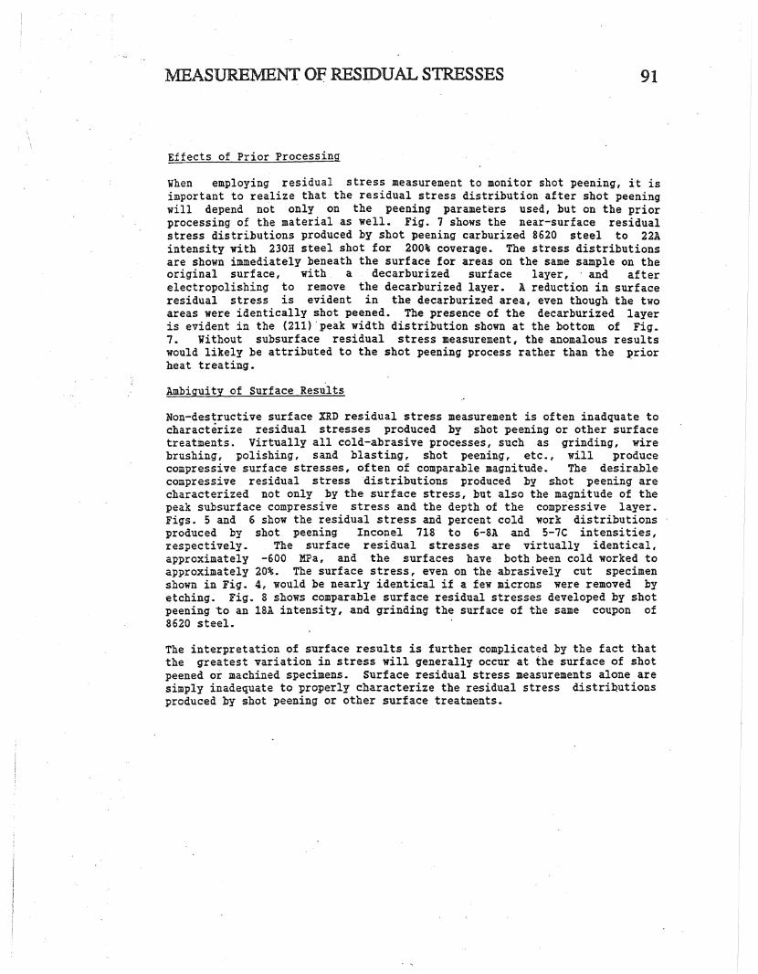
Effects of Prior Processing
91
When employing residual stress measurement to monitor shot peening, it isimportant to realize that the residual stress distribution after shot peeningwill depend not only on the peening parameters used, but on the priorprocessing of the material as well. Fig. 7 shows the near-surface residualstress distributions produced by shot peening carburized8620 steel to 22Aintensity with 230H steel shot for 200% coverage. The stress distributionsare shown immediately beneath the surface for areas on the same sample on theoriginal surface, with a decarburized surface layer,' and afterelectropolishing to remove the decarburized layer. A reduction in surfaceresidual stress is evident in the decarburized area, eVen though the twoareas were identically shot peened. The presence of the decarburized layeris evident in the (211) .peak width distribution shown at the bottom of Fig.7. Without subsurface residual stress measurement, the anomalous resultswould likely be attributed to the shot peening process rather than the ~rior
heat treating.
Ambiguity of Surface Results
Non-destructive surface XRD residual stress measurement is often inadquate tocharacterize residual stresses produced by shot peening or other surfacetreatments. Virtually all cold-abrasive processes l such as grinding, wirebrushing, polishing, sand blasting, shot peening, etc., will producecompressive surface stresses, often of comparable magnitude. The desirablecompressive residual stress "distributions produced hy shot peening arecharacterized not only by the surface stress, but also the magnitude of thepeak subsurface compressive stress and the depth of the compressive layer.Figs. 5 and 6 show the residual stress and percent cold work distributionsproduced by shot peening Inconel 718 to 6-8A and 5-1C intensities l
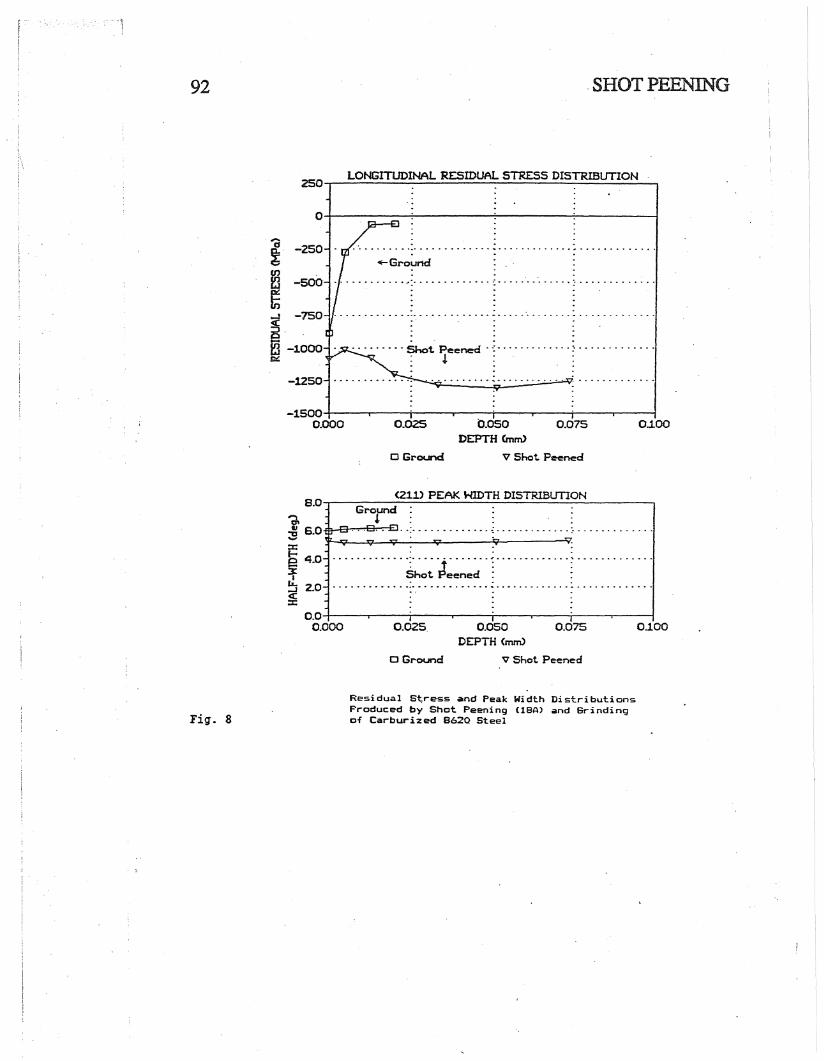
respectively. The surface residual stresses are virtually identical,approximately -600 MFa, and the surfaces have both been cold worked toapproximately 20%. The surface stress, even on the abrasively cut specimenshown in Fig. 4, would be nearly identical if a few microns were removed byetching~ Fig. 8 shows comparable surface residual stresses developed by shotpeening to an 18A intensity, and grinding the surface of the same coupon of8620 steel.
The interpretation of surface results is further complicated by the fact thatthe greatest variation in stress will generally occur at the surface of shotpeened or machined specimens. Surface residual stress measurements alone aresimply inadequate to ~roperly characterize the residual stress distri~utions
produced by shot peening or other surface treatments.
92 .SHOT PEENING
LONGITUDINAL RESIDUAL STRESS DISTRIBUTION250-,..-----------------------
O..-...------..;.-.-----~-----..-.;.-------i
...Ground
. . ........... _._ •••••••••••• " ••••••••••••• .; D ••••••
. ,...a~. -250
~ -500' : 00.0 •••• -: ••••••••••••• :- •• 0 ••••••••••
~ .. . .~ -750 :0...•.......•. -•...... - - .
~ ·-1000 . . Shot Peened' -; : '"c:; !..
-1250
0.1000.0750.050DEPTH Cmm>
V Shot Peened
0.025
o Ground
-lS00~-----.;..------?------......--------1
0.000
<21.1) PEAK WIDTH DISTRIBUTION8.0.....---
G-
ro-und---:-------------------..
~ :
i=~ 4.0 ~~~J~~~..( ~ .~ 2.0 ':., - = : .«:c
1~ 6.0"""'--~~~~··:········o ~ :.. - .. o .v--Q---.:cr---1;t...----J;;;t.-----l~----JV
0.1000.0750.050DEPTH (mm)
V Shot Peened
0.025.
Cl Ground
O.O-l---.....---------------r--------;..----.----f0.000
Fig. 8
Residual S~ress ~nd Peak Width DistributionsProduced by Shot Peening (lEA) and Grindingof Carburized 862Q Steel

~ASUREMENT OF RESIDUAL STRESSES
CONCLUSIONS
93
1. X-ray diffraction (XRD) residual stress measurement is the best developedand most accurate method available for "the characterization of the residualstress distributions produced by shot .peening. However, a thoroughunderstanding of the method and proper technique are required to achieveaccurate results. Caution is warranted in interpreting the results obtained,particularly non-destructive surface measurements.
2. The residual stress distributions produced by shot peening will dependupon by the prior thermal-mechanical history of the surface layers. Residualstress measurement alone may be inadquate to verify that shot peening wasperformed to a specific specification. Subsurface measurement, coupled withline broadening information, offers the most reliable tool for qualitycontrol of shot peening.
3. A given level of surface compressive residual stress is a necessary, butnot sufficient, condition to indicate that shot .peening was performedproperly. Many surface treatments other than shot peening produce similarlevels of surface compression, as will shot peening to different lImenintensities.
4. Subsurface residual stress measurement, with correction for penetrationof the x-ray beam and stress relaxation caused by electropolishing, isnecessary to accurately and reliably characterize residual stressdistrihutions produced by shot peening.
REFERENCES
1. HILLEY, M.E., ed., "R~sidual Stress Measurement by X-ray Diffraction,"SAE J784a, Society of Automotive Engineers, Warrendale, PA (1971).
2. ASTM, "Standard Method for Verifying the Alignment of X-ray DiffractionInstrumentation for Residual Stress Measurement," E915, Vol. 3.01,.Philadelphia, PA, 809-812, (1984).
3. PREVEY, P.S., "The Use of Pearson VII Distribution Functions in X-RayDiffraction Residual Stress Measurement," Adv. In X-Ray Analysis, Vol.29, Plenum Press, NY, 103-112, (1986).
4.. PREVEY, P. s. t. "A Method of Determining the Elastic Properties of Alloysin Selected Crystallographic Directions for X-ray Diffraction ResidualStress Measurement," Adv. in X-ray Analysis, Vol. 20, Plenum Press, NY,345-354, (1977).
5. MOORE, M.C. and EVANS, V.P., "Mathematical Corrections for Stressin Removed Layers in X-Ray Diffraction Residual Stress Analysis,n SAETrans., Vol. 66, (1958).
6. HILLEY, M.E., ed., SAE J784a, 61, {1977}.
7. KOISTINEN, D.P. and MARBURGER, R.E., Trans ASM, Vol. 51,· 537 ~ (1959).