Embed Size (px)
Citation preview

- 1 - Nikon Metrology UK Ltd Kerastari 13th June 2012
X-ray Tomography of the
Antikythera Mechanism
Andrew Ramsey
Nikon Metrology UK Ltd
(formerly X-Tek Systems Ltd)

- 2 - Nikon Metrology UK Ltd Kerastari 13th June 2012
X-ray Tomography of the Antikythera Mechanism
• The history of the Antikythera Mechanism
• Who were X-Tek and how did we get involved?
• Computed Tomography – What is it?
• Why is our CT different to medical CT?
• Microfocus X-ray sources – how do we magnify?
• High energy X-ray sources – how can we see through metal?
• Previous X-ray studies of the Mechanism
• What equipment did we use?
• How can we can see buried features using CT?
• The findings… What is the Mechanism?
- 3 - Nikon Metrology UK Ltd Kerastari 13th June 2012
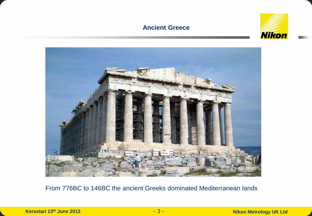
From 776BC to 146BC the ancient Greeks dominated Mediterranean lands
Ancient Greece

- 4 - Nikon Metrology UK Ltd Kerastari 13th June 2012
The Ancient Greeks were masters in many of the arts and sciences…
Ancient Greek Computing???

- 5 - Nikon Metrology UK Ltd Kerastari 13th June 2012
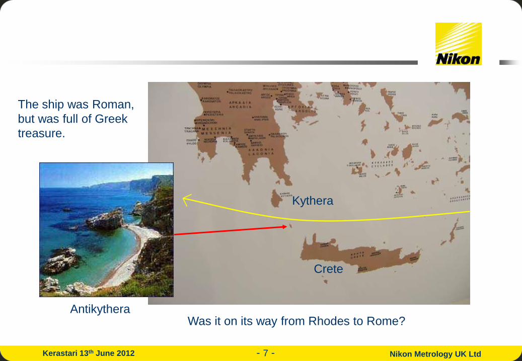
In 1900 sponge divers sheltered from a storm just off the island of Antikythera (the
one before Kythera!) in the Mediterranean between Crete and Greece. Afterwards
they decided to dive and found an ancient shipwreck – a veritable treasure-ship. As
well as dozens of marble and bronze statues, jewellery and other loot, they found a
small wooden box.

- 6 - Nikon Metrology UK Ltd Kerastari 13th June 2012
The box lay in a cupboard in the National Archaeological Museum in Athens and
wasn’t studied well until 1950 when an Englishman, Derek de Solla Price* studied
it. Inside the rapidly decaying box he found the remains of a bronze geared
mechanism of remarkable workmanship.
* Scientific American, June 1959, pp. 60-67
After many years of studying the
numbers of teeth on the gear wheels
Price formed the theory that the
Antikythera Mechanism was an early
astronomical computing machine.
Was this the world’s first computer?
- 7 - Nikon Metrology UK Ltd Kerastari 13th June 2012
Antikythera
Kythera
Crete
The ship was Roman,
but was full of Greek
treasure.
Was it on its way from Rhodes to Rome?

- 8 - Nikon Metrology UK Ltd Kerastari 13th June 2012
“…the orrery recently constructed by our
friend Posidonius, which at each
revolution reproduces the motion of the
sun, the moon and the five planets that
take place in the heavens every day and
night…”
Marcus Tullius Cicero, De Natura
Deorum, ~79 BC
Picture courtesy of “Mediterranean Archaeology and Archaeometry”,
Vol. 2, No. 2, pp.45-58 by Tony Freeth

- 9 - Nikon Metrology UK Ltd Kerastari 13th June 2012
Who are Metris X-Tek and how did we get involved?
• X-Tek was a small family-owned company based in Tring in Great Britain.
• It is now part of Nikon Metrology, owned by Nikon Corporation, Japan.
• In Tring we design and manufacture X-ray inspection equipment, for both
real-time imaging (live X-ray images) and 3D CT ( = Computed Tomography)
The small market town of
Tring
- 10 - Nikon Metrology UK Ltd Kerastari 13th June 2012
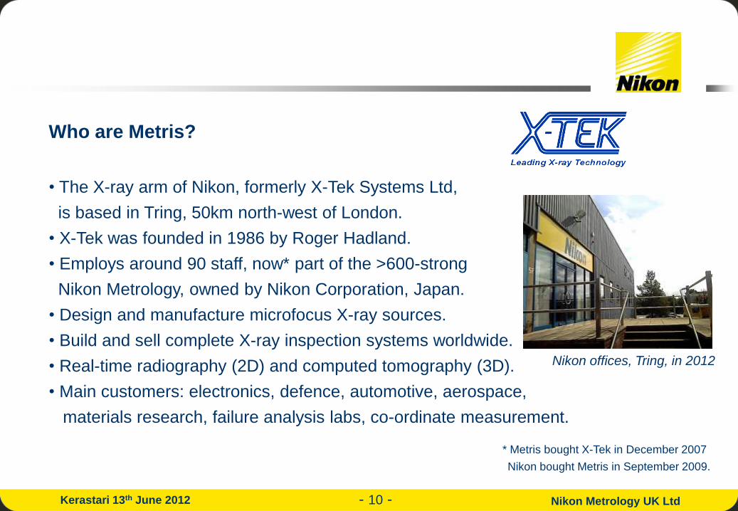
Who are Metris?
• The X-ray arm of Nikon, formerly X-Tek Systems Ltd,
is based in Tring, 50km north-west of London.
• X-Tek was founded in 1986 by Roger Hadland.
• Employs around 90 staff, now* part of the >600-strong
Nikon Metrology, owned by Nikon Corporation, Japan.
• Design and manufacture microfocus X-ray sources.
• Build and sell complete X-ray inspection systems worldwide.
• Real-time radiography (2D) and computed tomography (3D).
• Main customers: electronics, defence, automotive, aerospace,
materials research, failure analysis labs, co-ordinate measurement.
* Metris bought X-Tek in December 2007
Nikon bought Metris in September 2009.
X-Tek offices, Tring, in 2005 Nikon offices, Tring, in 2012

- 11 - Nikon Metrology UK Ltd Kerastari 13th June 2012
X-Tek – How did we get involved?
• First approached by Tony Freeth, a freelance film-maker based in
London, in 2000.
• Aware of our high-resolution computed tomography (CT) expertise.
• Tony asked could we do this and did we want to get involved?
• X-Tek sales staff: “Of course!”
• Tony: “When I get the funding…”
5 years later:
• But when Roger and our R&D team finally looked into what the
mechanism comprised, they realised we needed to do quite a bit of
development work!
Tony Freeth
Roger Hadland

- 12 - Nikon Metrology UK Ltd Kerastari 13th June 2012
What imaging technique did we use and why is it new?
• We used Microfocal X-ray Computed Tomography (known as “µCT”).
• Most people’s experience of CT is in a medical CT scanner in a hospital:
In a medical CT scanner the priorities
are:
• fast scan speed;
• low X-ray dose to patient;
• good views of organic material.

- 13 - Nikon Metrology UK Ltd Kerastari 13th June 2012
What is different about X-Tek’s µCT?
• X-Tek’s Microfocal Computed Tomography differs from standard medical X-ray
imaging in that it has:
a much smaller spot size (down to 1µm) –
allows magnification.
much higher energy X-rays (medical: 70kV,
we can use up to 450kV) and no limit on dose.
a more sensitive detector – so we can see
more subtle differences.
a more precise sample manipulator – for
better alignment during reconstruction.

- 14 - Nikon Metrology UK Ltd Kerastari 13th June 2012
What are X-rays?
• X-rays are electromagnetic radiation just like visible light, infra-red light,
ultra-violet light and radio waves, but with a much shorter wavelength than
any of these.
X-Tek X-ray sources produce energies in the range 30-450keV (in red).

- 15 - Nikon Metrology UK Ltd Kerastari 13th June 2012
How do we generate X-rays?
• We generate X-rays by firing electrons at high speed on to a metal target.
• Electrons are produced from a hot filament (like a light bulb).
• They are accelerated using a high voltage into a beam tube.
• They travel at up to 80% the speed of light (giving them energies of 30 - 450keV).
• They are focused by a magnetic lens into a small spot (1 – 5µm) onto a metal target.
• The sudden deceleration of the charged electrons when they hit the target produces
99.3% heat and 0.7% X-rays.

- 16 - Nikon Metrology UK Ltd Kerastari 13th June 2012
e-
Conical X-ray beam
Metal target at earth potential
e-
e-
Magnetic lens
Filament (at -
225kV) Focus cup
How we generate X-rays:

- 17 - Nikon Metrology UK Ltd Kerastari 13th June 2012
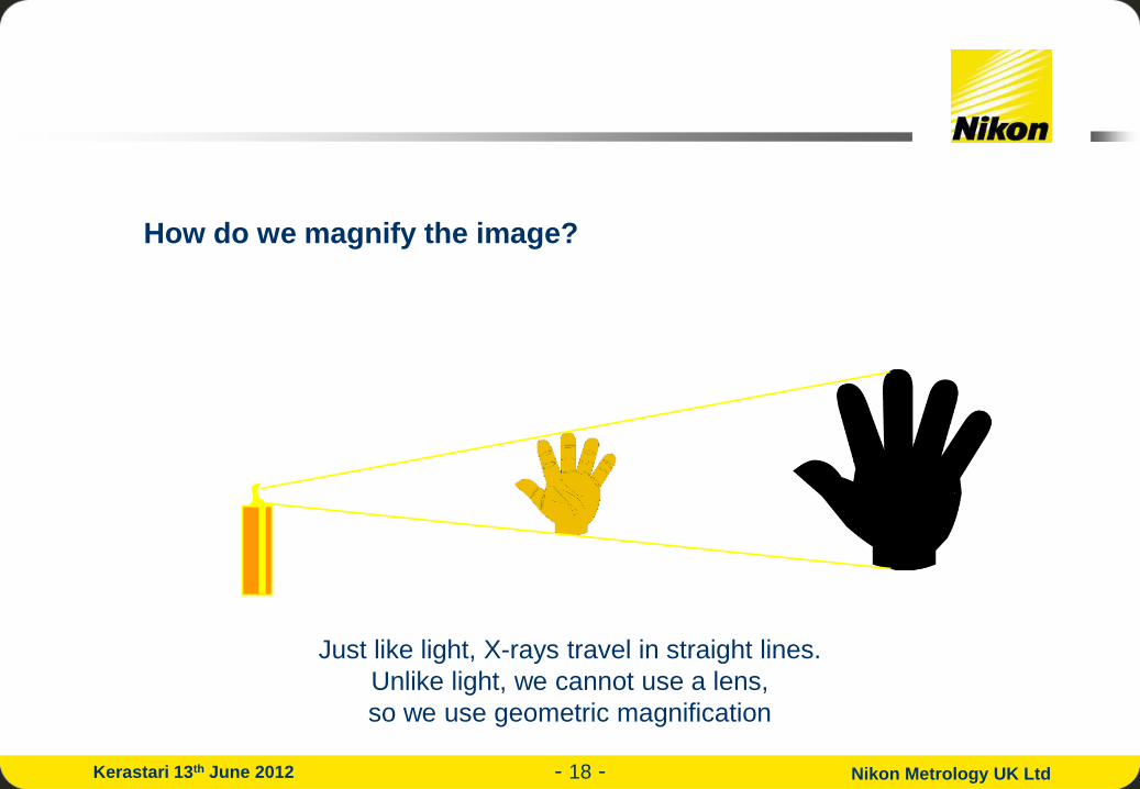
How do we magnify the image?
Just like light, X-rays travel in straight lines.
Unlike light, we cannot use a lens,
so we use geometric magnification
- 18 - Nikon Metrology UK Ltd Kerastari 13th June 2012
How do we magnify the image?
Just like light, X-rays travel in straight lines.
Unlike light, we cannot use a lens,
so we use geometric magnification
- 19 - Nikon Metrology UK Ltd Kerastari 13th June 2012
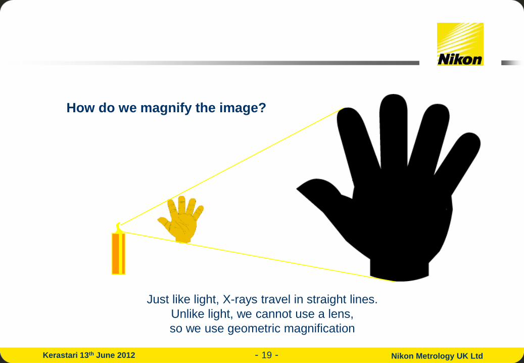
How do we magnify the image?
Just like light, X-rays travel in straight lines.
Unlike light, we cannot use a lens,
so we use geometric magnification

- 20 - Nikon Metrology UK Ltd Kerastari 13th June 2012
The magnification can be increased by moving the sample
closer to the X-ray source.
450kV X-ray source
Detector

- 21 - Nikon Metrology UK Ltd Kerastari 13th June 2012
What is microfocal X-ray computed tomography?
• Microfocal means that the size of the X-ray source is only a few microns across
(1 micron or 1µm is 1/1000th of one millimetre).
• Using a small X-ray source means that we can magnify the X-ray images on to
the detector and thus see more detail.
Microfocus source
(~3µm) Typical medical
X-ray source
(~1mm)
Large sharp image Large blurred image
Object

- 22 - Nikon Metrology UK Ltd Kerastari 13th June 2012
How do we keep the image sharp
when we magnify?
An optical analogy here is the difference between the shadow cast by a
small light source, such as a candle and that cast by a larger light source,
such as a window.
- 23 - Nikon Metrology UK Ltd Kerastari 13th June 2012
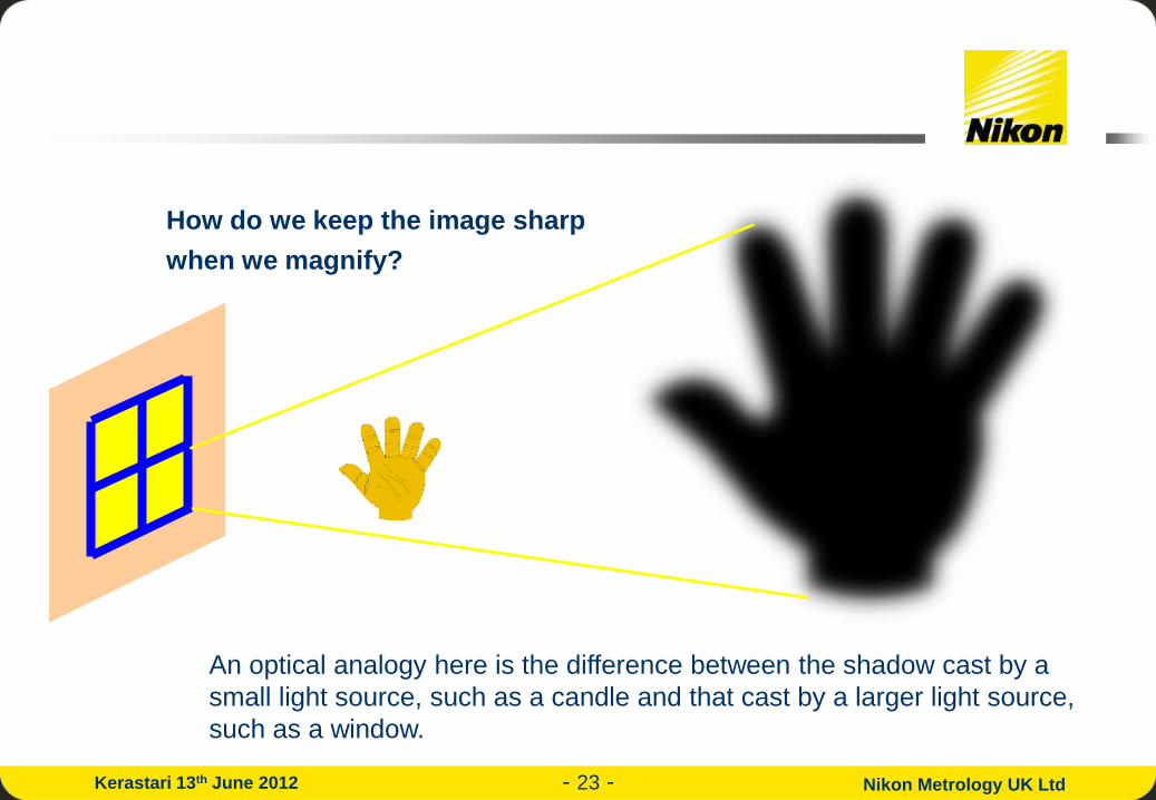
How do we keep the image sharp
when we magnify?
An optical analogy here is the difference between the shadow cast by a
small light source, such as a candle and that cast by a larger light source,
such as a window.

- 24 - Nikon Metrology UK Ltd Kerastari 13th June 2012
Why do we need higher energy X-rays?
• Medical X-rays typically have energies of 70 – 140kV.
• They can penetrate bone but are stopped by only a few mm of metal.
• The Mechanism is made of bronze and the largest fragment is ~120mm across.
• So much higher energy X-rays are needed.
• Nikon (X-Tek) is the only company in the world which has a
microfocus X-ray source which can generate X-rays with
such penetrating power.
Wilhelm Röntgen’s first radiograph (1895): the low energy X-
rays penetrated the bone but not the gold ring.

- 25 - Nikon Metrology UK Ltd Kerastari 13th June 2012
How do we image the X-rays?
• The magnified shadow of the object is imaged using an
amorphous silicon flat panel detector which comprises:
• a 400x400mm fluorescent screen which converts the X-ray
energy into light to form an image,
• an array of 2000x2000 light-sensitive diodes, each
200x200µm in size.
• electronics to allow this image to be read by the computer
with a precision of 1 part in 65536 (16 bits).
A 2k x 2k 16-bit panel
kindly lent to us by
PerkinElmer, later
purchased.

- 26 - Nikon Metrology UK Ltd Kerastari 13th June 2012
Electronics
Medical
Castings
… and complex mechanisms!
Seam at
the top
of a
drinks
can
Battery
A blown fuse
X-rays can be used to see
more than just bones!

- 27 - Nikon Metrology UK Ltd Kerastari 13th June 2012
What is Computed Tomography?
• Computed Tomography (or CT) is the process of imaging an object from all directions
using penetrating radiation (e.g. X-rays) and using a computer to reconstruct the internal
3-D structure of the object from the intensity values in the projected images.
• It is the process used in a medical CT scanner, though in our case we keep the source and
detector stationary and rotate the object. Hospital patients might complain if we did this to them!

- 28 - Nikon Metrology UK Ltd Kerastari 13th June 2012
CT requires us to penetrate the object with X-rays from all directions:
The intensity must not fall to zero at any angle
X-ray source
Intensity vs pixel position
Detector
Turntable
with sample

- 29 - Nikon Metrology UK Ltd Kerastari 13th June 2012
CT requires us to penetrate the object with X-rays from all directions:
The intensity must not fall to zero at any angle
X-ray source
Intensity vs pixel position
Detector
Turntable
with sample
- 30 - Nikon Metrology UK Ltd Kerastari 13th June 2012
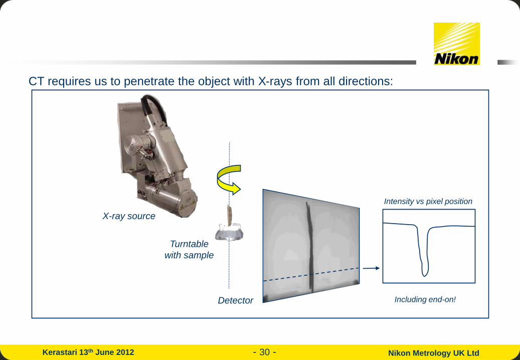
CT requires us to penetrate the object with X-rays from all directions:
Including end-on!
X-ray source
Intensity vs pixel position
Turntable
with sample
Detector

- 31 - Nikon Metrology UK Ltd Kerastari 13th June 2012
From thousands of images like these a computer algorithm
generates a 3D volume which can be sliced in software to
reveal details hidden under the corrosion.

- 32 - Nikon Metrology UK Ltd Kerastari 13th June 2012
But how does Computed Tomography (CT) actually work?
• First we process each of the images (using a filter) to remove the blurring
which simply projecting them through the volume would cause.
• Then we project them through the volume, adding in one image after another
at the rotation angle it was collected at.
• For each rotation angle, the intensity of the pixel (point in the image) on to
which each point in the volume (voxel) projects (draw a line from the source
through the voxel to the detector) is added into the volume.
• At the end of all the projection angles the volume is complete.

- 33 - Nikon Metrology UK Ltd Kerastari 13th June 2012
But how does Computed Tomography (CT) actually work?
Each voxel is projected on to the pixel that a line from the source through that voxel
hits. The intensity of this pixel is added into the voxel. This is repeated for all images.
So for 3000 images, each of the billion or so voxels is processed 3000 times. That’s
why it used to take a long time to reconstruct CT volumes! (Typically 1 hour in 2005.)
Pre-filtered
projection image
Detector
Source
Reconstruction volume

- 34 - Nikon Metrology UK Ltd Kerastari 13th June 2012
But how does Computed Tomography (CT) actually work?
Horizontal slices through a CT volume as projections are added:
Left – right: top: 4, 8, 16, bottom: 32, 64, 128 images added.

- 35 - Nikon Metrology UK Ltd Kerastari 13th June 2012
For a good quality CT volume we need 1000s of projection images.
To collect these in a reasonable time we used continuous rotation.
Typical scans were 20 mins (1500 images) & 40 mins (3000 images).
The displacement of an edge pixel from
one angle to the next must be no more
than the size of one voxel (=3D pixel)
in the volume.
How many images do we need to collect for a CT scan?

- 36 - Nikon Metrology UK Ltd Kerastari 13th June 2012
Previous X-ray studies of the Mechanism:
• 1971: First radiographed (on film) by Price –
model made.
• 1990: X-ray laminography by Michael Wright –
new model made*.
• 2005: New X-ray 3D CT inspection by Tony
Freeth / Mike Edmunds (a collaboration of Athens
Kapodistrian University, University of Thessaloniki,
Cardiff University, X-Tek Systems Ltd, Hewlett
Packard – funded by the Leverhulme Trust).
* Michael Wright “Understanding the Antikythera Mechanism”, Athens Press Conference, October 2005
An early radiograph of Fragment A
on film by Price (1970).

- 37 - Nikon Metrology UK Ltd Kerastari 13th June 2012
Model of the mechanism, in the
National Archaeological Museum in
Athens, made by Derek de Solla
Price from early X-ray film images

- 38 - Nikon Metrology UK Ltd Kerastari 13th June 2012
Michael Wright,
formerly of the
Science Museum,
London, showing
Tony Freeth his
hand-built
reconstruction of
the Antikythera
Mechanism in
Athens, 2006.
Wright and Alan
Bromley performed
laminography on
many of the
fragments in 1980
and Wright has
since decoded
much of the
mechanism’s
structure.

- 39 - Nikon Metrology UK Ltd Kerastari 13th June 2012
Tony Freeth,
London
Mike Edmunds,
Cardiff Univ.
Some of the X-Tek team The HP team
Xenophon, Yanis & Agamemnon,
Athens Univ.
John Seiradakis,
Thessaloniki Univ.
And the staff of the National Archaeological Museum, Athens
The New Team

- 40 - Nikon Metrology UK Ltd Kerastari 13th June 2012
Material: Corroded bronze. Size of largest fragment: 120mm.
For solid bronze:
Each mm reduces the X-ray intensity at 200kV by 4x ...Transmission through 120mm 10-70 %
At 400kV this drops to 2x ...Transmission through 120mm 10-37 %
We were hoping for a lot of corrosion!

- 41 - Nikon Metrology UK Ltd Kerastari 13th June 2012
But Nikon/X-Tek runs an X-ray CT inspection service…

- 42 - Nikon Metrology UK Ltd Kerastari 13th June 2012
So, why not simply ship the mechanism to Tring…?
But of course, the Mechanism is far too fragile to be transported anywhere,
so…

- 43 - Nikon Metrology UK Ltd Kerastari 13th June 2012
We had to ship the X-ray system to Greece!
All 8 tonnes of it.
X-Tek car park at 1am!

- 44 - Nikon Metrology UK Ltd Kerastari 13th June 2012
4 days later, after 2500 km of roads, the system arrived in Athens

- 45 - Nikon Metrology UK Ltd Kerastari 13th June 2012
And was delivered to the National Archaeological Museum
- 46 - Nikon Metrology UK Ltd Kerastari 13th June 2012
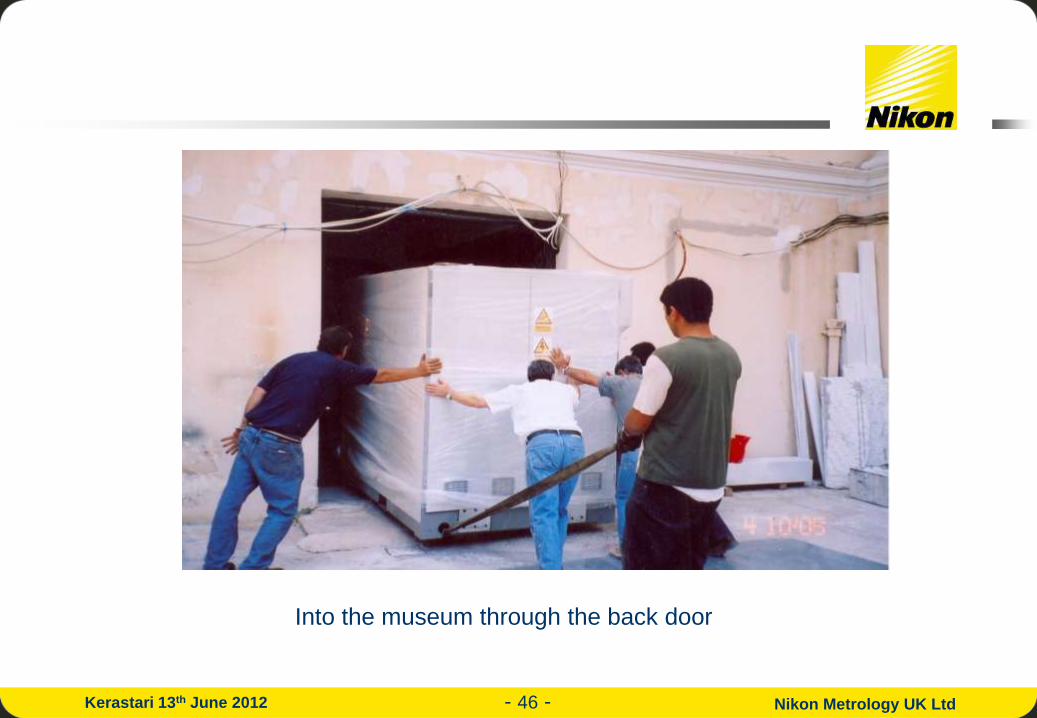
Into the museum through the back door

- 47 - Nikon Metrology UK Ltd Kerastari 13th June 2012
Unpacking the system
- 48 - Nikon Metrology UK Ltd Kerastari 13th June 2012
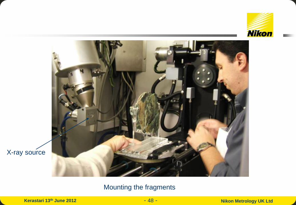
Mounting the fragments
X-ray source

- 49 - Nikon Metrology UK Ltd Kerastari 13th June 2012
Fragment A

- 50 - Nikon Metrology UK Ltd Kerastari 13th June 2012
Most of X-Tek’s low energy (up to 225kV) open-
tube sources are single ended with the target at
ground potential, allowing the sample to be
placed very close to the source and so giving
very high magnification.
X-Tek’s R&D team had worked hard to develop
the fore-runner to our new double-ended system
which can now generate X-rays up to 450kV
whilst maintaining a small focal spot (~50µm).
This extra penetrating power would be very
helpful in inspecting the larger fragments.
X-Tek’s new 450kV microfocus X-ray source:

- 51 - Nikon Metrology UK Ltd Kerastari 13th June 2012
How does X-Tek achieve such a high voltage?
• Most microfocal X-ray sets achieve 225kV with no problem using a target at ground
potential.
• X-Tek have taken a second 225kV tube and raised the potential of the target to +225kV
to attract the already fast-moving electrons.
• So the total potential that the electrons are accelerated through is 450kV.
• We can now produce X-rays with energies up to 450keV from a region about 50µm in
size.
• The positive module can be taken off and replaced with a 5µm standard lens for
inspecting small objects at 225kV or lower.

- 52 - Nikon Metrology UK Ltd Kerastari 13th June 2012
Mounting the smaller fragments

- 53 - Nikon Metrology UK Ltd Kerastari 13th June 2012
Some of the people involved

- 54 - Nikon Metrology UK Ltd Kerastari 13th June 2012
Watching the CT data being collected
- 55 - Nikon Metrology UK Ltd Kerastari 13th June 2012
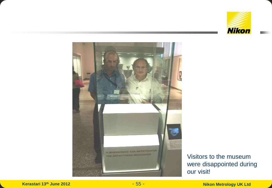
Visitors to the museum
were disappointed during
our visit!

- 56 - Nikon Metrology UK Ltd Kerastari 13th June 2012
Results:
• In just over two weeks we collected 600 GB of data.
• It took several months of effort to count all the teeth on the gears and
decipher the text.
• Full results were presented at a conference in Athens in November 2006.
• Here is a summary:

- 57 - Nikon Metrology UK Ltd Kerastari 13th June 2012
One of dozens of gear wheels
inside the mechanism
fragments.
Note writing on gear wheel.
Note serifs on the letters!
~30mm Mike Edmunds didn’t believe it was real!

- 58 - Nikon Metrology UK Ltd Kerastari 13th June 2012
Writing and
divisions on the
scales
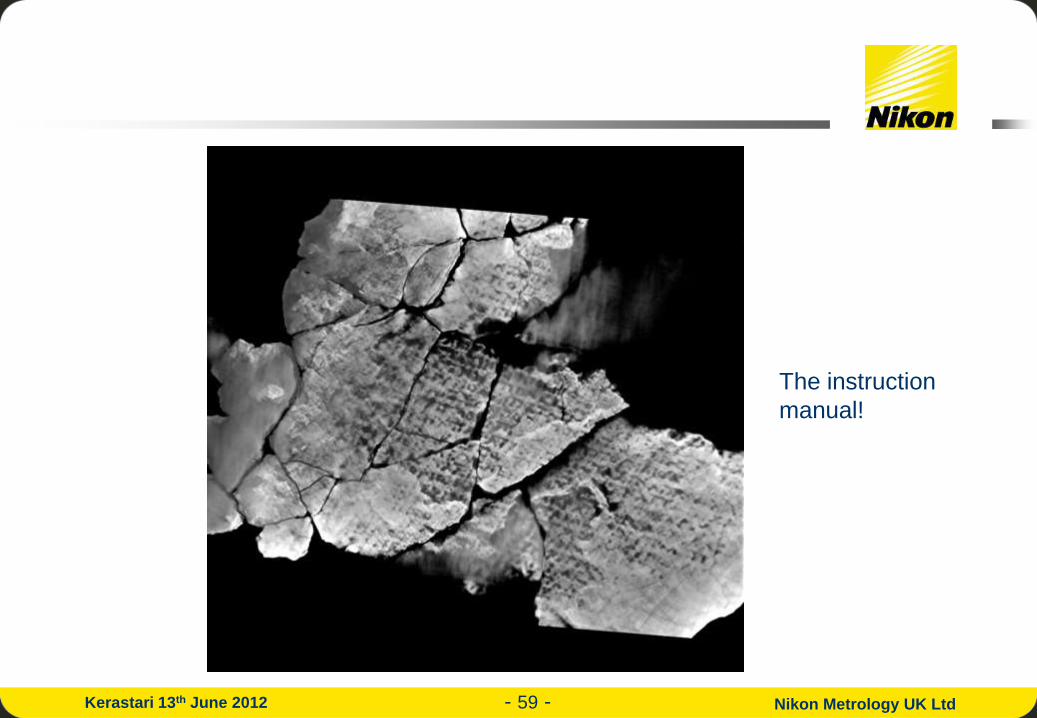
- 59 - Nikon Metrology UK Ltd Kerastari 13th June 2012
The instruction
manual!

- 60 - Nikon Metrology UK Ltd Kerastari 13th June 2012
How do we see the text in a CT scan when it doesn’t show up in a radiograph?
Letters punched into
bronze plate
CT cutting plane
(row of voxels)
Position
Intensity in CT slice
The voxels need to be smaller than the depth of punching of the letters.
Intensity in the radiograph
Slice position
Intensity

- 61 - Nikon Metrology UK Ltd Kerastari 13th June 2012
Reading the text is not easy.
The CT slices are flat, the plate is
not, so the slice needs to be
moved around to see all the text,
which can then be pieced
together. Each time you move the
slice plane, it takes a few seconds
for the computer to redraw the
image.
= chrysoun sfairion (golden sphere)
- 62 - Nikon Metrology UK Ltd Kerastari 13th June 2012

- 63 - Nikon Metrology UK Ltd Kerastari 13th June 2012
CT slices through
Fragment A from
front to back.

- 64 - Nikon Metrology UK Ltd Kerastari 13th June 2012
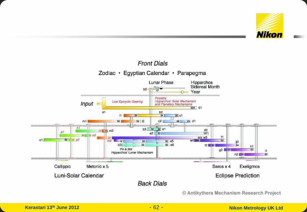
The CT results showed that the Antikythera Mechanism was a complex lunar-
solar calendar which modelled the position of the Sun and the Moon (and
possibly Mercury and Venus) against the background stars.
Using a set of eccentric gears and a pin and slot mechanism it modelled the
elliptical nature of the Moon’s orbit around the Earth.
By recording solar and lunar eclipses on a 223-month spiral lunar calendar scale
(the length of the Saros, or eclipse-repeat period = 18 years, 11 days, 8 hrs), the
Mechanism was able to predict not only the months in which eclipses could
occur, but also the time of day. It is not yet clear whether the records were
historical (possibly Babylonian dating back to 600BC) or were predicted by the
Mechanism itself.
By showing that eclipses in successive cycles occur 8 hours later the Mechanism
shows awareness of eclipses happening on the other side of the (round*) world.
* Eratosthanes calculated the diameter of the Earth in about 250BC, and got a value of 13525km
(true value = 12757km)
- 65 - Nikon Metrology UK Ltd Kerastari 13th June 2012
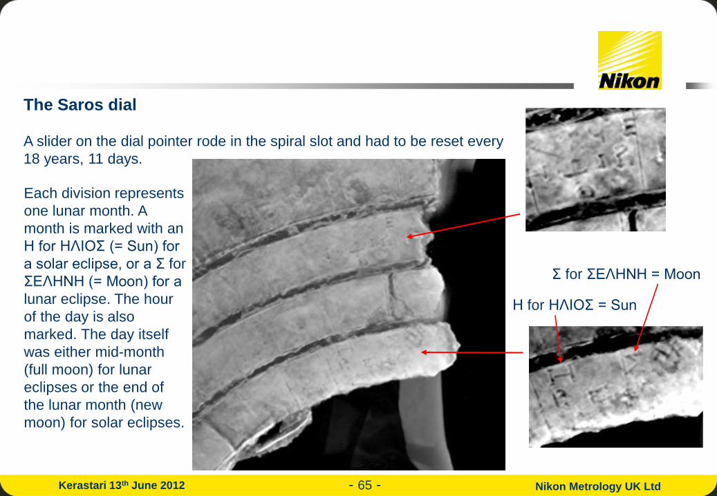
Η for ΗΛΙΟΣ = Sun
Σ for ΣΕΛHΝH = Moon
Each division represents
one lunar month. A
month is marked with an
Η for ΗΛΙΟΣ (= Sun) for
a solar eclipse, or a Σ for
ΣΕΛHΝH (= Moon) for a
lunar eclipse. The hour
of the day is also
marked. The day itself
was either mid-month
(full moon) for lunar
eclipses or the end of
the lunar month (new
moon) for solar eclipses.
The Saros dial
A slider on the dial pointer rode in the spiral slot and had to be reset every
18 years, 11 days.

- 66 - Nikon Metrology UK Ltd Kerastari 13th June 2012
The dial pointer on the spiral Saros dial had a “pointer-follower” which rode in the spiral groove.
Every 18 years and 11 days it had to be reset by hand.
Left: Magnified CT slices
through Fragment A
Right: Reconstructed
model of pointer-follower

- 67 - Nikon Metrology UK Ltd Kerastari 13th June 2012
The Moon’s elliptical motion is driven by a pin on one gear and a slot in an
eccentric gear above this. As the pin slides up & down in the slot, the speed of
the gear varies, just as the Moon’s speed varies in its elliptical orbit.

- 68 - Nikon Metrology UK Ltd Kerastari 13th June 2012
A recreation of the front dials of the Antikythera Mechanism by Dionysis Kriaris
Half-silver, half-black
lunar sphere
Golden solar sphere

- 69 - Nikon Metrology UK Ltd Kerastari 13th June 2012
A recreation of the Olympiad dial – a 4-year dial showing which games are taking place
Olympia
Pythia
Nemea
Isthmia

- 70 - Nikon Metrology UK Ltd Kerastari 13th June 2012

- 71 - Nikon Metrology UK Ltd Kerastari 13th June 2012
Thank you to all my colleagues at Nikon Metrology,
especially:
For more info see: http://www.xtekxray.com/antikythera.htm &
http://www.antikythera-mechanism.gr
For more on Nikon Metrology see: www.nikonmetrology.com
Martin Allen
David Bate
Bob Brailey
Alan Crawley
Roger Hadland
And to the Antikythera Research
Project team for inviting X-Tek to
participate.
Ian Haig
Peter Hockley
Andrew Ray
Matt Williams

- 72 - Nikon Metrology UK Ltd Kerastari 13th June 2012
X-ray Tomography of the
Antikythera Mechanism _
Thank you!
Σας ευχαριστούμε!
For more info see: http://www.xtekxray.com/antikythera.htm &
http://www.antikythera-mechanism.gr
For more on Nikon Metrology see: www.nikonmetrology.com