Embed Size (px)
Citation preview
www.monash.edu.au
Introduction to Data Modelling: Entity Relationship Modelling
IMS1002 /CSE1205 Systems Analysis and Design

www.infotech.monash.edu.au
2
Data Modelling
• Focus on the information aspects of the organisation
• In a database environment many applications share the same data
• The database is a common asset and corporate resource
• Corporate and application level data modelling
www.infotech.monash.edu.au
3
Conceptual Data Modelling
• A conceptual data model is a representation of organisational data
• Captures the structure, meaning and interrelationships amongst the data
• Independent of any data storage and access method, DBMS, platform issues
• Occurs in parallel with other systems analysis activities

www.infotech.monash.edu.au
4
• Identification of information requirements• Allows integration of data across the
organisation and across applications• Helps eliminate problems of data
inconsistency and duplication across the organisation
Conceptual Data Modelling

www.infotech.monash.edu.au
5
• Techniques;– Entity Relationship (ER) modelling
– Normalisation
– Data Structure Diagrams (DSD)
• Good modelling techniques are supported by rigorous standards and conventions to remove ambiguity and aid understanding
Conceptual Data Modelling
www.infotech.monash.edu.au
6
Entity Relationship Modelling
• Used for conceptual data modelling• Diagrammatic technique used to represent:
– things of importance in an organisation - entities
– the properties of those things - attributes
– how they are related to each other -
relationships
www.infotech.monash.edu.au
7
• Entity relationship (ER) models can be readily transformed into a variety of technical architectures
• All information about the system’s data identified during conceptual data modelling must be entered into the data dictionary or repository
• This assists in checking the consistency of data and process models
Entity Relationship Modelling
www.infotech.monash.edu.au
8
• Data “objects” or entities are things about which we wish to store information
• ER models show the major data objects and the associations between them
• ER models are useful in the initiation, analysis and design phases
Entity Relationship Modelling
www.infotech.monash.edu.au
9
Entity
• Something of interest about which we store information
eg. EMPLOYEESALES ORDERSUPPLIER
• Often identified from nouns used within the business application
• Should be LOGICAL (not physical)
www.infotech.monash.edu.au
10
Identifying Entities
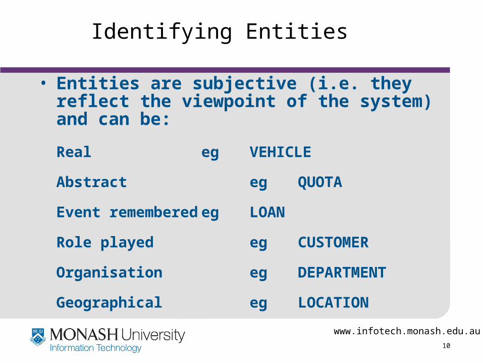
• Entities are subjective (i.e. they reflect the viewpoint of the system) and can be:
Real eg VEHICLE
Abstract eg QUOTA
Event remembered eg LOAN
Role played eg CUSTOMER
Organisation eg DEPARTMENT
Geographical eg LOCATION
www.infotech.monash.edu.au
11
Representing Entities
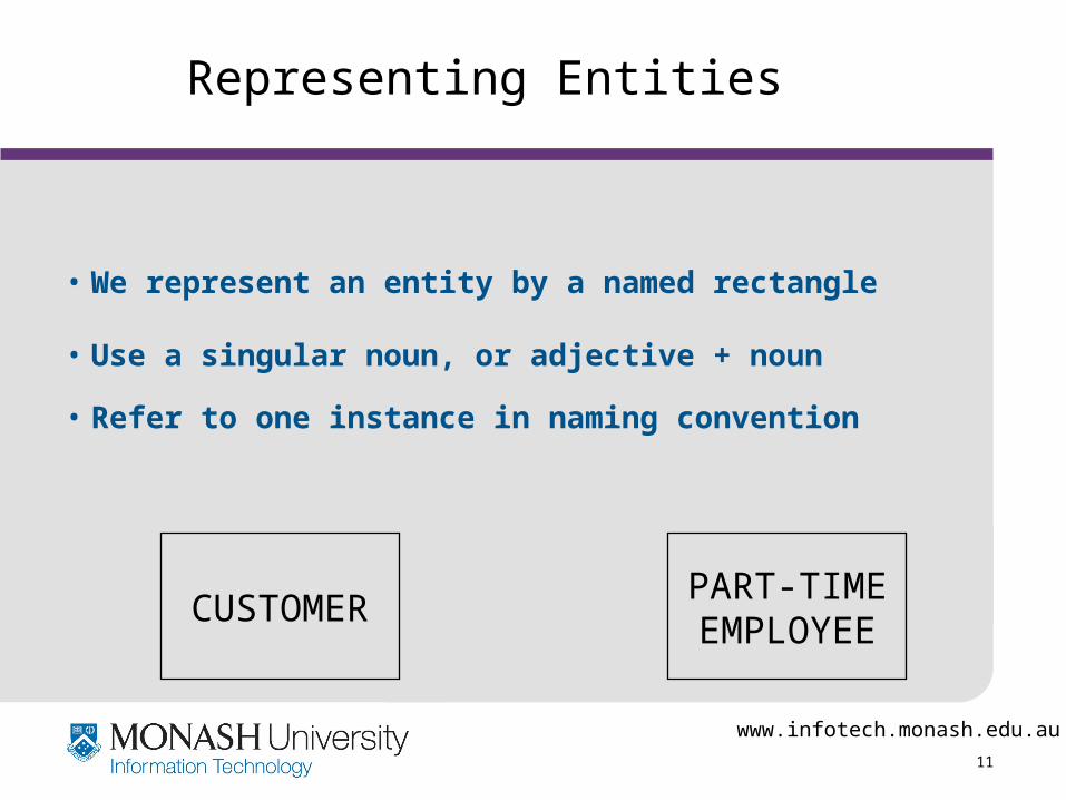
• We represent an entity by a named rectangle
• Use a singular noun, or adjective + noun
• Refer to one instance in naming convention
PART-TIMEEMPLOYEE
CUSTOMER
www.infotech.monash.edu.au
12
Entity Types and Instances
• An entity type is a classification of entity instances
eg BN Holdings ABC Engineering Acme Corp. Ltd.
SUPPLIER
www.infotech.monash.edu.au
13
Entity Types are Logical
• E.g. in a sales and inventory system there might be 3 physical forms of data:– a stock file
– product brochures sent to customers enquiring about products
– a product range book used by salespeople when calling on customers to take orders
which could be represented by one logical entity
PRODUCT
www.infotech.monash.edu.au
14
Entity Types are Logical
• E.g. in a Student Records System there might be an entity type STUDENT which represents some of the data used in several physical forms of data:
>Student re-enrolment forms
>Subject class lists
>Student results file
The ER model identifies the minimum set of data objects necessary to construct the data used within the system in its various physical forms.
www.infotech.monash.edu.au
15
Relationship
• Is an association between two entities
• We may wish to store information about the association
• Often recognised by a verb or "entity” + verb + “entity"
eg CUSTOMER places ORDER
• Relationships capture the "business rules" of the system
www.infotech.monash.edu.au
16
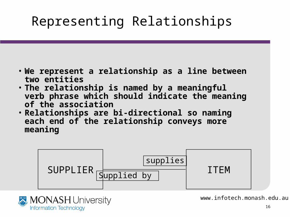
Representing Relationships
• We represent a relationship as a line between two entities
• The relationship is named by a meaningful verb phrase which should indicate the meaning of the association
• Relationships are bi-directional so naming each end of the relationship conveys more meaning
SUPPLIER ITEMsupplies
Supplied by

www.infotech.monash.edu.au
17
Relationship Types and Instances
• A relationship type is a classification of relationship instances
MIS FinanceMarketing
John SmithBill BrownSue Blackemploys
employsemploys
DEPT EMPLOYEEemploys
www.infotech.monash.edu.au
18
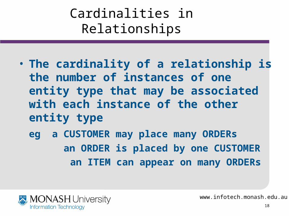
Cardinalities in Relationships
• The cardinality of a relationship is the number of instances of one entity type that may be associated with each instance of the other entity type
eg a CUSTOMER may place many ORDERs
an ORDER is placed by one CUSTOMER
an ITEM can appear on many ORDERs
www.infotech.monash.edu.au
19
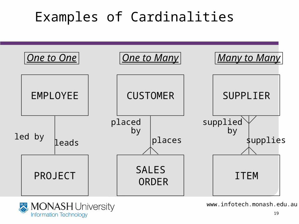
Examples of Cardinalities
EMPLOYEE CUSTOMER SUPPLIER
PROJECTSALES
ORDERITEM
leads places supplies
One to One One to Many Many to Many
led by
placed by
supplied by
www.infotech.monash.edu.au
20
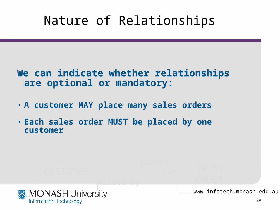
Nature of Relationships
We can indicate whether relationships are optional or mandatory:
• A customer MAY place many sales orders
• Each sales order MUST be placed by one customer
CUSTOMER SALESORDER
places
placed by

www.infotech.monash.edu.au
21
Notations
EMPLOYEE
COURSE
attends
EMPLOYEE
COURSE
attends
Is attended by
Notation used in Hoffer et al (1999) Notation used in Whitten et al (2001)

www.infotech.monash.edu.au
22
Notations
EMPLOYEE
EMPLOYEE
EMPLOYEE
EMPLOYEE
EMPLOYEE
EMPLOYEE
or Exactly one
One and only one
Zero or one
One or more
Zero, one or more
More than one
www.infotech.monash.edu.au
23
Relationship Degree
• The degree of a relationship is the number of entity types that participate in the relationship.
• The most common relationships in ER modelling in practice are:
unary (degree one)
binary (degree two)
ternary (degree three)
www.infotech.monash.edu.au
24
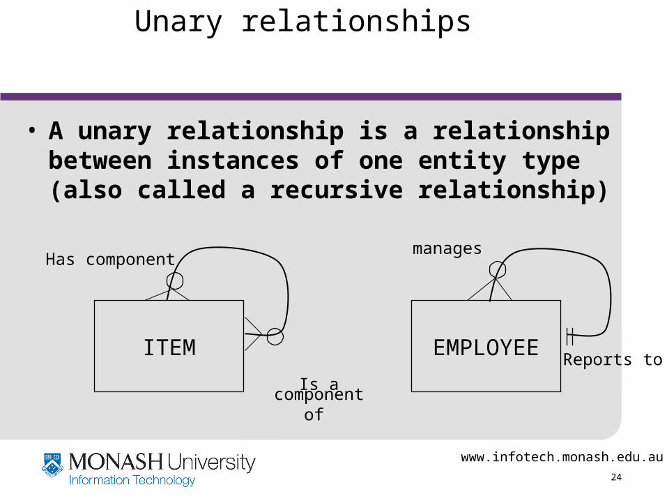
Unary relationships
• A unary relationship is a relationship between instances of one entity type (also called a recursive relationship)
EMPLOYEEITEM
Has component manages
Reports to
Is a componentof
www.infotech.monash.edu.au
25
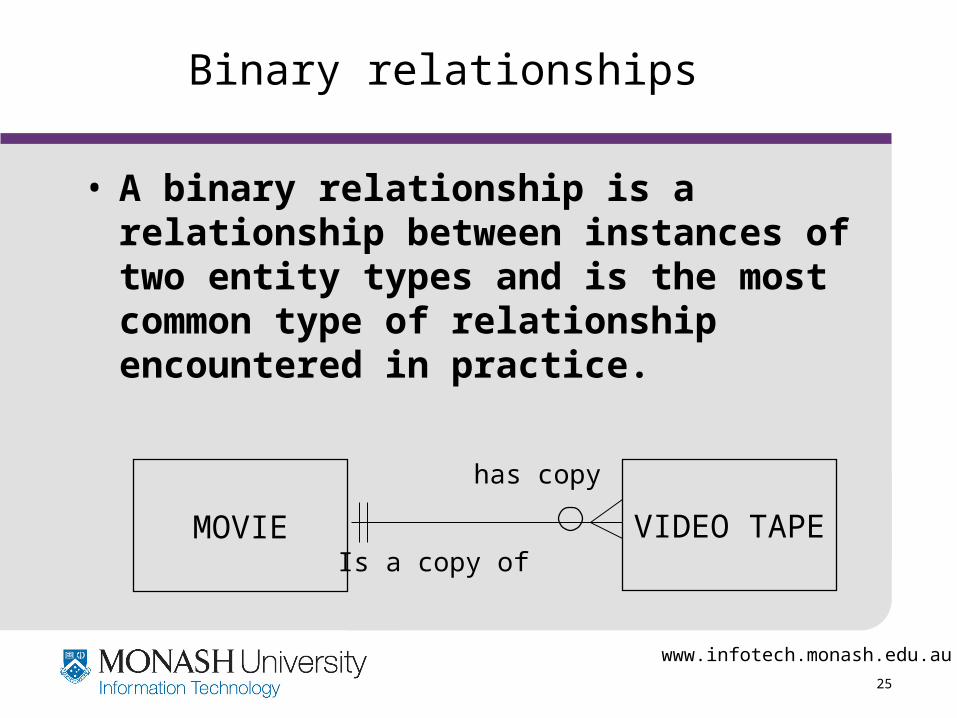
Binary relationships
• A binary relationship is a relationship between instances of two entity types and is the most common type of relationship encountered in practice.
MOVIE VIDEO TAPE
has copy
Is a copy of
www.infotech.monash.edu.au
26
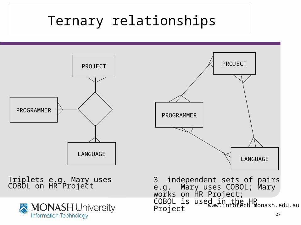
Ternary relationships
• A ternary relationship is a simultaneous relationship between instances of three entity types.
• A ternary relationship is NOT the same as three binary relationships between the same three entity types.
www.infotech.monash.edu.au
27
Ternary relationships
PROGRAMMER
PROJECT
LANGUAGE
PROGRAMMER
PROJECT
LANGUAGE
Triplets e.g. Mary uses COBOL on HR Project
3 independent sets of pairs e.g. Mary uses COBOL; Mary works on HR Project;COBOL is used in the HR Project

www.infotech.monash.edu.au
28
Example ER model
CUSTOMER
ITEM
SALESORDER
EMPLOYEE
employs
made by
places
is on
employed by
makes
placed by
is for
DEPARTMENT
www.infotech.monash.edu.au
29
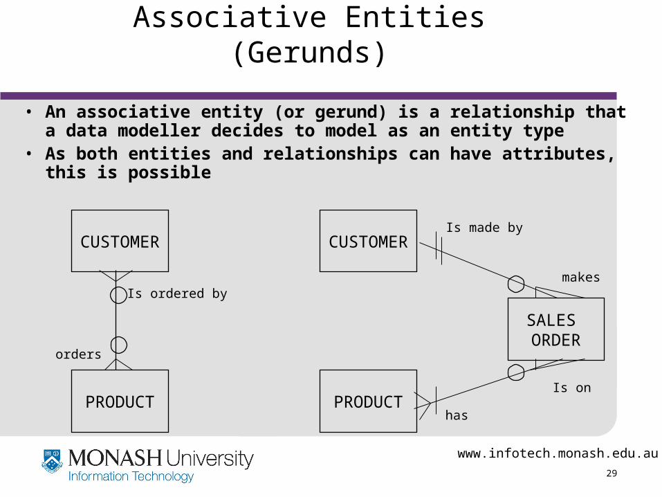
Associative Entities (Gerunds)
• An associative entity (or gerund) is a relationship that a data modeller decides to model as an entity type
• As both entities and relationships can have attributes, this is possible
PRODUCT
CUSTOMER
Is ordered by
orders
PRODUCT
CUSTOMER
SALES ORDER
makes
Is made by
has
Is on
www.infotech.monash.edu.au
30
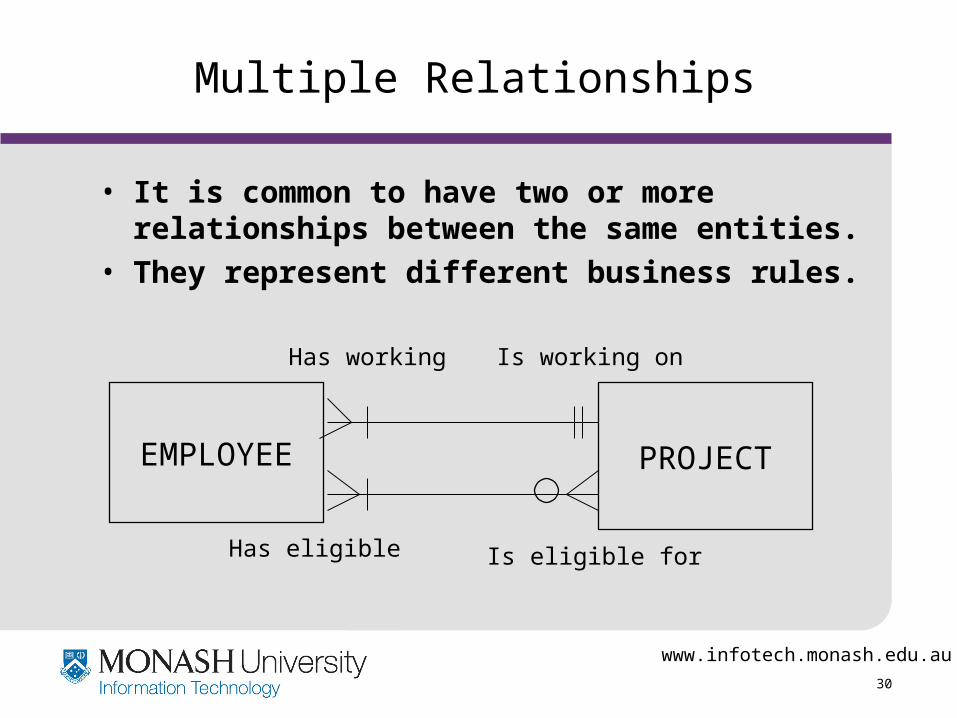
Multiple Relationships
• It is common to have two or more relationships between the same entities.
• They represent different business rules.
EMPLOYEE PROJECT
Is working on
Is eligible for
Has working
Has eligible

www.infotech.monash.edu.au
31
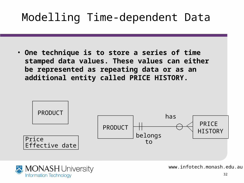
Modelling Time-dependent Data
• Some data values vary over time and it may be important to store a history of data values to understand trends and for forecasting.E.g. for accounting purposes we are likely to need a history of costs of material and labour costs and the time period over which each cost was in effect.
• Modelling time-dependent data can result in changes to entities, attributes and relationships.
www.infotech.monash.edu.au
32
• One technique is to store a series of time stamped data values. These values can either be represented as repeating data or as an additional entity called PRICE HISTORY.
Modelling Time-dependent Data
PRODUCTPRICE
HISTORY
has
belongsto
PRODUCT
PriceEffective date
www.infotech.monash.edu.au
33
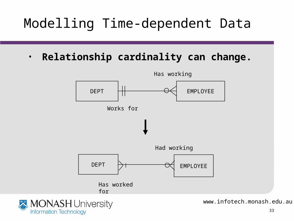
Modelling Time-dependent Data
• Relationship cardinality can change.
DEPT EMPLOYEE
Works for
DEPT EMPLOYEE
Has worked for
Has working
Had working

www.infotech.monash.edu.au
34
Entity subtypes and supertypes
• Some entities can be generalised (or specialised) to form other entities
• An entity subtype is made up from some of the instances of the entity
E.g. the entity types
motor cartrucktrain
can be grouped together to form the entity supertypetransport vehicle
www.infotech.monash.edu.au
35
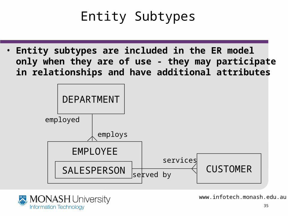
Entity Subtypes
• Entity subtypes are included in the ER model only when they are of use - they may participate in relationships and have additional attributes
SALESPERSON
EMPLOYEE
DEPARTMENT
CUSTOMER
employs
services
employed
served by
www.infotech.monash.edu.au
36
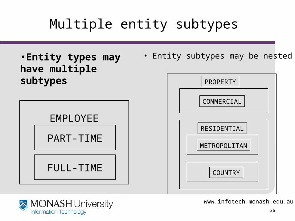
Multiple entity subtypes
EMPLOYEE
PART-TIME
FULL-TIME
PROPERTY
RESIDENTIAL
METROPOLITAN
COUNTRY
COMMERCIAL
• Entity subtypes may be nested•Entity types may have multiple subtypes

www.infotech.monash.edu.au
37
Entity Subtypes
Multiple entity subtypes should be• Non-overlapping (disjoint)• Collectively exhaustive
This enables easier translation to a relational design
EMPLOYEE
PART-TIME
SALARIED
RESIDENTIAL
METROPOLITAN
COMMERCIAL
PROPERTY
? ?
www.infotech.monash.edu.au
38
Building a Basic ER Model
• Identify and list the major entities in the system
• Represent the entities by named rectangles
• Identify, draw, name, and quantify relationships • Indicate mandatory/optional nature of
relationships
• Revise for entity subtypes where appropriate

www.infotech.monash.edu.au
39
Example ER model
• Airline ticketing model
FLIGHT
TICKET
PASSENGER
AIRLINEROUTE
AIRLINE
AIRPORT
COUPON
for
made up of
scheduled as
arrival
departure
operated by
shown on
See Barker (1989), chap 2.4

www.infotech.monash.edu.au
40
Eliciting Information for an ER Model
• Fact-finding and information gathering techniques are used to determine the entities and relationships
• Identify both existing and new information
• Existing documents are particularly useful e.g. forms, paper-based and computer files, reports, listings, data
manuals, data dictionary
• Existing and new business rules for information are often difficult to elicit from documents ... it is essential to speak directly to the client
www.infotech.monash.edu.au
41
ER Modelling Difficulties
• Is a given object an entity or relationship ?• Are two similar objects one entity or two ?• Is a given object an entity or an attribute of
(data item about) an entity?e.g. EMPLOYEE and EMPLOYEE SPOUSE
• Do we need to store data about the object?• What is the 'best' data model ?
www.infotech.monash.edu.au
42
Quality dimensions
• Correctness
• Completeness
• Understandability
• Simplicity
• Flexibility
www.infotech.monash.edu.au
43
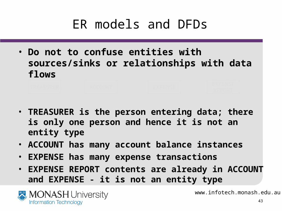
ER models and DFDs
• Do not to confuse entities with sources/sinks or relationships with data flows
• TREASURER is the person entering data; there is only one person and hence it is not an entity type
• ACCOUNT has many account balance instances
• EXPENSE has many expense transactions
• EXPENSE REPORT contents are already in ACCOUNT and EXPENSE - it is not an entity type
EXPENSEREPORT
ACCOUNTTREASURER EXPENSE
www.infotech.monash.edu.au
44
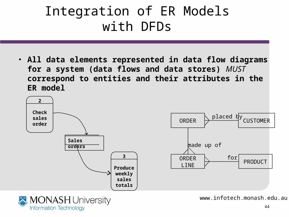
Integration of ER Models with DFDs
• All data elements represented in data flow diagrams for a system (data flows and data stores) MUST correspond to entities and their attributes in the ER model
ORDER CUSTOMERplaced by
ORDERLINE
PRODUCTfor
made up of
2
Check sales order
3
Produce weekly sales totals
Sales orders
www.infotech.monash.edu.au
45
Barker, R. (1989) CASE*METHOD Entity Relationship Modelling, Addison-Wesley, Wokingham UK. Chapters 4,5
Hoffer, J.A., George, J.F. and Valacich, J.S., (1999)., Modern Systems Analysis and Design, (2nd ed), Benjamin/Cummings, Massachusetts. Chapter 10
Whitten, J.L. & Bentley, L.D. and Dittman, K.C., (2001), Systems Analysis and Design Methods, (5th edn.), McGraw Hill Irwin, Boston MA USA. Chapter 7
References