Embed Size (px)
Citation preview

Before attempting to connect or operate this product,please read these instructions carefully and save this manual for future use.
Model No. WV-CS554WV-CS854A
Combination CameraOperating Instructions
ENGL
ISH
FRAN
ÇAIS
2
The serial number of this product may be foundon the top of the unit.You should note the serial number of this unit inthe space provided and retain this book as a per-manent record of your purchase to aid identifica-tion in the event of theft.
Model No.
Serial No.
WARNING:To reduce the risk of fire or electric shock, do not expose this appliance to rain or moisture.
The lightning flash with arrow-head symbol, within an equilater-al triangle, is intended to alert theuser to the presence of uninsu-lated "dangerous voltage" withinthe product's enclosure that maybe of sufficient magnitude to con-stitute a risk of electric shock topersons.
The exclamation point within anequilateral triangle is intended toalert the user to the presence ofimportant operating and mainte-nance (servicing) instructions inthe literature accompanying theappliance.
CAUTION: TO REDUCE THE RISK OF ELECTRIC SHOCK,DO NOT REMOVE COVER (OR BACK).
NO USER-SERVICEABLE PARTS INSIDE.REFER SERVICING TO QUALIFIED
SERVICE PERSONNEL.
CAUTIONRISK OF ELECTRIC SHOCK
DO NOT OPEN
SA 1965
SA 1966
NOTE: This equipment has been tested andfound to comply with the limits for a Class A digi-tal device, pursuant to Part 15 of the FCC Rules.These limits are designed to provide reasonableprotection against harmful interference when theequipment is operated in a commercial environ-ment. This equipment generates, uses, and canradiate radio frequency energy and, if notinstalled and used in accordance with the instruc-tion manual, may cause harmful interference toradio communications.Operation of this equipment in a residential areais likely to cause harmful interference in whichcase the user will be required to correct the inter-ference at his own expense.
FCC Caution: To assure continued compliance,(example - use only shielded interface cableswhen connecting to computer or peripheraldevices). Any changes or modifications notexpressly approved by the party responsible forcompliance could void the user’s authority tooperate this equipment.
For U.S.A

3
CONTENTSPREFACE ................................................................................................................ 4FEATURES .............................................................................................................. 4
Camera Cleaning ............................................................................................. 5 Preset Data Uploading or Downloading ........................................................... 5
PRECAUTIONS ....................................................................................................... 5CONSTRUCTION .................................................................................................... 7SETUP ..................................................................................................................... 8
Setup Menu ...................................................................................................... 8 Setup Menu Description ................................................................................... 11
SETTING PROCEDURES ....................................................................................... 16 Menu Display .................................................................................................... 16 Preset ............................................................................................................... 17 Deleting Preset Positions .................................................................................. 22 Home Position Setting ...................................................................................... 22 Self Return Setting ............................................................................................ 22 Auto Mode Setting ............................................................................................ 23 AUTO PAN KEY Setting .................................................................................... 24 DIGITAL FLIP ON/OFF ..................................................................................... 25 LOCAL/REMOTE Setting .................................................................................. 25 SPECIAL 1 ........................................................................................................ 25 Camera Setting ................................................................................................. 35 RS485 Setup ...................................................................................... 46
INSTALLATION ....................................................................................................... 48CONNECTIONS ...................................................................................................... 53SYSTEM CONNECTIONS ........................................................................................ 55PREVENTION OF BLOOMING AND SMEAR .......................................................... 56SPECIFICATIONS .................................................................................................... 56ACCESSORIES ........................................................................................................ 58OPTIONAL ACCESSORIES ..................................................................................... 58APPENDIX ............................................................................................................... 59
ENGL
ISH

4
• High quality picture of 755 x 485 pixels.
• Super Dynamic2 extends the dynamicrange up to 46 dB.
• Minimum illumination of 1 lx for color, 0.06 lxfor black and white , or 2 lx .
• 64 preset positions for , 8 presetpositions for .
• Auto Black/White mode enables the camerato switch between C/L and B/W in responseto input lights .
• Digital Flip allows a 180 degree tilting totrace passing objects right under the cam-era.
• Privacy zone settings veil unwanted zonesso as not to be displayed on the monitor.
• A run of manual operations is memorized inPATROL LEARN for repetitive use in future.
• Built-in digital motion detector and alarm out-put.
• Protocol adaptability to Panasonic’s proto-col.
• Automatic gain control circuit
• Image hold
• Digital noise reduction effect
FEATURES
Symbols Used in This InstructionsThis operating instructions is included both of thecombination cameras WV-CS554 and WV-CS854A.It uses the icons shown below to describe thefunctions available with each model.
Functions only with the WV-CS554Combination CameraFunctions only with the WV-CS854A Combination Camera
Panasonic presents highly advanced CCTV tech-nology that meets the demands of new and ever-changeing applications.This high-performance combination color cam-era is utilized as a video surveillance device.The camera incorporates the Super-Dynamic2Digital Signal Processor, pan-tilt mechanism and
PREFACE22 times zoom lens in a compact enclosure. Anewly developed 1/4-inch CCD is employed foruse under extremely low light conditions.It also assures clear display of pictures in whichbright and dark objects coexist without mutualinterference thanks to the Super-D 2 DSP.

5
1. Do not attempt to disassemble the cam-era.To prevent electric shock, do not removescrews or covers.There are no user-serviceable parts inside.Ask a qualified service personnel for servic-ing.
2. Handle the camera with care.Do not abuse the camera. Avoid striking,shaking, etc. The camera could be dam-aged by improper handling or storage.
3. Do not expose the camera to rain or mois-ture, not try to operate it in wet areas.This product is designed for indoor use orlocations where it is protected from rain andmoisture.Turn the power off immediately and ask aqualified service personnel for servicing.Moisture can damage the camera and alsocreate the danger of electric shock.
PRECAUTIONS
Camera CleaningEven if this function is used, it may be produced noise on the monitor screen, or the preset position maybe deviated in the cause of prolonged use.In case of these, set the REFRESH mode on the special 2 menu (see page 46).
To use with the WJ-SX550B Matrix Switcher, set the auto cleaning function on each unit side, then cleanWV-CS554/WV-CS854A one time a day.
Preset Data Uploading or Downloading To download the preset data from video camera to system controller or to upload the downloaded data tocamera, set the following functions to OFF.
Downloading or uploading the data may not work normally if these functions are set to ON.• Alarm (see page 31)
• Preset alarm (see page 34) • Cleaning (see page 33)• Motion detection (see page 42) • Auto mode (see page 23)• Self return (see page 22)
Aim the camera at a motionless object such as a wall if possible.
Note: Take notice of the following cases when uploading the downloaded data to a camera.• Preset positions may vary. If a preset position varies, delete the preset position and set the cor-
rect preset position newly.• If a preset data of WV-CS854A is uploaded to lower level models (e.g. WV-CS854, WV-CS554,
etc.), an error may occur and uploading may not be completed successfully.
6
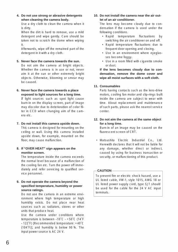
4. Do not use strong or abrasive detergentswhen cleaning the camera body.Use a dry cloth to clean the camera when itis dirty.When the dirt is hard to remove, use a milddetergent and wipe gently. Care should betaken not to scratch the dome when wipingit.Afterwards, wipe off the remained part of thedetergent in it with a dry cloth.
5. Never face the camera towards the sun.Do not aim the camera at bright objects.Whether the camera is in use or not, neveraim it at the sun or other extremely brightobjects. Otherwise, blooming or smear maybe caused.
6. Never face the camera towards a placeexposed to light sources for a long time.If light sources such as spot light causeburn-in on the display screen, part of imagemay discolor due to deterioration of color fil-ter in CCD when changing aim of the cam-era etc.
7. Do not install this camera upside down.This camera is designed for mounting on theceiling or wall. Using this camera installedupside down, for example, mounted on thefloor, may cause malfunction.
8. If “OVER HEAT” sign appears on themonitor screen.The temperature inside the camera exceedsthe normal level because of a malfunction ofthe cooling fan etc. Turn the power off imme-diately and refer servicing to qualified ser-vice personnel.
9. Do not operate the camera beyond thespecified temperature, humidity or powersource ratings.Do not use the camera in an extreme envi-ronment where high temperature or highhumidity exists. Do not place near heatsources such as radiators, stoves or otherunits that produce heat.Use the camera under conditions wheretemperature is between –10˚C - +50˚C (14˚F- 122˚F) [Recommended temperature: +40˚C(104˚F)], and humidity is below 90 %. Theinput power source is AC 24 V.
To prevent fire or electric shock hazard, use aUL listed cable, VW-1, style 1015, AWG 18 orUL listed power supply cord, type SJT shouldbe used for the cable for the 24 V AC inputterminals.
CAUTION
10. Do not install the camera near the air out-let of an air conditioner.The lens may become cloudy due to con-densation if the camera is used under thefollowing conditions.
• Rapid temperature fluctuations byswitching the air conditioner on and off.
• Rapid temperature fluctuations due tofrequent door opening and closing.
• Use in an environment where eyeglas-ses become foggy.
• Use in a room filled with cigarette smokeor dust.
If the lens becomes cloudy due to con-densation, remove the dome cover andwipe all moist surfaces with a soft cloth.
11. ConsumablesParts having contacts such as the lens-drivemotors, cooling fan motor and slip-rings builtinside the camera are subject to wear withtime. About replacement and maintenanceof such parts, please ask the nearest servicecenter.
12. Do not aim the camera at the same objectfor a long time.Burn-in of an image may be caused on thefluorescent screen of CRT.
• Matsushita Electric Industrial Co., Ltd.Herewith declares that it will not be liable forany damage, whether direct or indirect,caused by using for business transaction orsecurity, or malfunctioning of this product.

7
w
e
r
t
q
y u
o
i
!0
y Camera Mounting Base
u Panning Start Point
i Fall Prevention Wire
o Decoration Cover
!0 Dome Cover
q Alarm Input Connector
w Alarm Output Connector
e Video Output Connector
r Data Port
t Power Cable
CONSTRUCTION

9
ShutterSpeed
Selection
AGCON/OFF
SensitivityUp
ON/OFF
WHITEBAL
AWC ATW
Super-D2OFF
Light Control
ALC/MANUAL
Super-D2ON
ManualLevel
Adjustment(Contrast)
ManualMaskArea
Selection
INTManual
Selection
VD2AutomaticSelection
ManualLevel
Adjustment
ManualLevel
Adjustment
V-phaseManual
Adjustment
LLManual
Selection
MotionDetectorON/OFF
ManualMaskArea
Selection
ManualLevel
Adjustment
CameraMenu
CAMERA IDEditing
CAMERA IDDisplay Position
SyncINT/LL
CameraResetSetting
Hue
Adjustment
Pedestal
Adjustment
APGain
Adjustment
ChromaGain
Adjustment
StopBit
Selection
ParityCheck
Selection
DataBit
Selection
BAUDRate
Selection
Sub-Address
Delay Time
Selection
Xon/Xoff
Selection
AlarmData
Selection
WaitTime
Selection
RS-485
Setup
UnitNumber
Selection
RS-485Setup
To A
A
Special2
BurstON/OFFSelection
Refresh
Setting
Digital NoiseReduction
Mode SelectionLOW1/LOW2/HIGH1/HIGH2
B/W
Selection
To
BAF MODESelection
B
8
Setup MenuSetup menus are shown in the diagram below. Various kinds of setup are available to have the camerafulfill your requirements. Menus are built in a hierarchical structure from the Setup menu at the top downto Manual Mask Area Selection at the bottom.These menus are described in the following pages for reference prior to setup.Switches, keys and the joystick are used for setup operations.
SETUP
Setup
Menu
HomePosition
Selection
SelfReturnSetting
Auto PanKey
Setting
DigitalFlip
ON/OFF
Local/Remote
Selection
PRESETMenu
Auto PanSettingMenu
PresetAlarm
ON/OFF
Image HoldON/OFF
EL-ZoomON/OFF
AlarmIN/OUTSetting
PasswordRegistration
PasswordVerification
CleaningDisplay
CleaningON/OFF
LearningDisplay
Patrol LearnPlay/Stop
ZoneParameter
Setting
ZoneNumber
Selection
Privacy ZoneON/OFF
Propo.P/T
ON/OFF
PasswordLock
ON/OFF
DirectionSetting
Area TitleDisplay
Area TitleEditing
AlarmIN/OUT
Area TitleSelection
AutoMode
Selection
Special1
PositionSetting
LightControl
ALC/MANUAL
Dwell TimeSetting
MAPMenu
PresetNo. SET
Menu
PresetID
Setting
PresetID
Editing
Scene FileSetting
ManualIris
Adjustment
Super-D2ON
Super-D2OFF
ManualMaskArea
Selection
ManualLevel
Adjustment(Contrast)
ElectronicSensitivity
Up ON/OFF
WhiteBalance
AWC ATW
MotionDetectorON/OFF
ShutterSpeed
ON/OFF
AGCON/OFF
AF ModeSelection
PresetSettingMenu
SensitivityLevel
Adjustment
ManualLevel
Adjustment
ManualLevel
Adjustment
MaskArea
Selection
DemonstrationDisplay

10
Function/Controller
Open Special 2 F2 key
The keys (switches) to use for setup are as shown in the table below. The joystick on the connected con-troller may also be used for setup. The table also shows the functions versus the operations of the individ-ual controllers. For further details, see the manual for the controller to be used. The switches and controlsare abbreviated as SW and CTRL in the table.
OPERATE LOGIN ALARM
FUNCTION
SX
IRIS
CLOSE OPEN
NEAR FAR
WIDE TELE
FOCUS
ZOOM
AUTO FOCUS
IRIS RESET
HOME
SET UP
ALM RECALL
CAM SETUP CAM FUNCTION
MULTI SCREEN DEF
WIPEREL-ZOOM
SHIFT
ALM RESET
VTR CAM
STILL
-1 CAM/DEC
ALM SUSPEND
+1 CAM/INC
PATROLSTOP
AUX 1
AUX 2
B/W UNIT
SEQ PAUSE
BOOST
SEQUENCE AUTOPRESET
POSI
FS
MON CAM
LOGOUTESC SET
CAMERA SITE CONTROL
UP
L R
DOWN
BUSY PROHIBITEDMONITORUNIT CAMERA
System Controller WV-CU 360
1 2 3
4 5 6
7 8 9
MON CAM
ESC SET
0
ACKRESET
BACKSEQ
FORWARDSEQ ALT
DEC–1CAM
INC+1CAM STOP1 2
AUX
CLOSE OPENIRIS
PRESET
FOCUSNEAR
ZOOMTELE
FARWIDE
System Controller WV-CU 550B
LEFT RIGHT
UP
DOWN
ALARM BUSY
F3 F4F2F1
AF
[WV-CU550B]
[WV-CU161]
[WV-RM70]
Joystick
CAM (SET)Key
MON (ESC)Key
CAM (SET)Key
MON (ESC)Key
SET KeyCAM (SET) Key
OPERATE REMOTE
NORMAL PROGALARMRESET
SYSTEMALARM OFF
Camera Controller WV-RM 7070
Up Switch
Set SwitchRightSwitch
Left Switch DownSwitch
[WV-CU360]Joystick
Joystick
FOCUS SwitchZOOM Switch
FOCUS SwitchZOOM Switch
Up Switch
R
System Controller WV-CU
1 2 3
4 6
7 8 9
0
5
SHIFT
OPERATE ALARM
RESET
RESET
SUSPEND
CAMERASETUP
PATROLPAY
PROGRAMPRESET
CAMERAFUNCTION
SERUP
ESC
HOME
SET
PRESET WIDE TELE
NEAR
AUX1
B/W
AUTO
WIPER
AUX2
DEF
UP
DOWN
LFAR
FOCUS
IRISCLOSS OPEN
PROGRAM
ALARM
IRIS RESET
AUTO FOCUS
Left Switch
Right Switch
Down Switch
WV-CU550B WV-CU360 WV-CU161 WV-RM70
Open CAM SETUP See page 16CAM SETUPkey (for 2 sec-onds or more)
CAMERA SETUPkey (for 2 seco-nds or more)
See page 16
Close CAM SETUP F4 keyCAM SETUPkey (for 2 sec-onds or more)
CAMERA SETUPkey (for 2 seco-nds or more)
PROG SW
Move the cursorJoystick(←, ↑ , ↓ , →)
Joystick(←, ↑ , ↓ , →)
Direction SW(←, ↑ , ↓ , →)
Direction SW(←, ↑ , ↓ , →)
Select a parameterJoystick(←, →)
Joystick(←, →)
Direction SW(←, →)
Direction SW(←, →)
Adjust the levelJoystick(←, →)
Joystick(←, →)
Direction SW(←, →)
Direction SW(←, →)
Move the cameradirection
Joystick(←, ↑ , ↓ , →)
Joystick(←, ↑ , ↓ , →)
Joystick(←, ↑ , ↓ , →)
Direction SW(←, ↑ , ↓ , →)
Zoom & FocusZOOM CTRL &FOCUS CTRL
ZOOM CTRL &FOCUS CTRL
ZOOM CTRL &FOCUS CTRL
Direction SW(←, ↑ , ↓ , →)
Enter the setting CAM (SET) key CAM (SET) key CAM (SET) key SET SW
Open a submenu CAM (SET) key CAM (SET) key CAM (SET) key SET SW
Enter CAM ID &PRESET IDdisplay position
MON (ESC) key MON (ESC) key SET keySET SW(for 2 seconds)
Enter MASKsetting
MON (ESC) key MON (ESC) key SET keySET SW(for 2 seconds)
All Reset F3 key4+5+6 key (for 2 secondsor more)
4+5+6 key (for 2 secondsor more)
R+SET+L SW(for 2 seconds)
4+6 key(for 2 secondsor more)
4+6 key(for 2 secondsor more)
R+L SW(for 2 seconds)
Notes:• A changed parameter is entered only when you move the cursor to
another item or open a new menu. A changed parameter will not beentered if the setup menu is closed without taking either of the abovesteps.
• Setting procedures in the following pages are described on theassumption that the camera is used with WJ-SX550B Matrix Switcherand WV-CU550B System Controller.

11
Setup Menu Description PRESET(1) Position (POSITION SET)
POSITION SET adjusts the camera picture by panning, tilting, zooming and focusing.See page 17 for the setting.
(2) Preset Identification (PRESET ID)A preset ID (identification of up to 16 alphanumeric characters) can be displayed on the screen.See page 19 for the setting.
(3) Light Control (ALC/MANUAL)ALC/MANUAL refers to the mode of the incoming light level control.See page 20 for the setting.
(4) Dwell Time (DWELL TIME)DWELL TIME is the duration that the picture of each camera position is displayed.You can select a preset duration from the menu.See page 21 for the setting.
(5) Scene File (SCENE FILE)SCENE FILE stores up to 10 files. Each file has a set of detailed parameters for Shutter Speed, AGC,Electronic Sensitivity Enhancement, White Balance, Motion Detector and AF mode. The scene filescan be recalled later to reproduce the parameter settings under the same conditions as stored in thefiles.See page 21 for the setting.
Home Position (HOME POSITION)HOME POSITION is the camera’s basic position. It returns to this position automatically, when a specifictime has elapsed after a manual operation. This setting functions only when AUTO MODE is OFF.See page 22 for the setting.
Self Return (SELF RETURN)SELF RETURN is the time-out parameter for returning to the home position. The camera returns to AUTOMODE if it is set to ON when a specific time has elapsed after a manual operation.See page 22 for the setting.
AUTO MODEAUTO MODE is for setting the movement of the camera. You can select one from the four automatic oper-ation modes and one manual operation mode as follows:OFF mode: No automatic operation. The camera can be operated only manually.SEQ mode: The camera operates in the sequence of preset positions in numerical order.SORT mode: The camera operates in the sequence of preset positions counterclockwise from Pan/Tilt
Starting Point.AUTO PAN mode: The camera automatically turns within the preset panning range.PATROL mode: The camera operates in the patrol learn function.See page 23 for the setting.

12
AUTO PAN KEYThis setting assigns SEQ, SORT, AUTO PAN or PATROL (PLAY) to the AUTO key on the controller. Aftersetting this, the AUTO key performs as assigned.Note: AUTO PAN LED on the controller does not light if something other than AUTO PAN is assigned.
DIGITAL FLIP ON/OFF Tilt range is limited within 0° to 90° if OFF is selected. If ON is selected it widens the range up to 180° withthe digital flip that reverses horizontal and vertical scanning when the camera is tilted through the 90°point (Downright position if the camera is installed on a ceiling). Tilt range narrows from 180° to 90° if PANLIMIT is set to ON.
LOCAL/REMOTEThis setting determines whether the camera continues or stops the ongoing auto operation when theSystem Controller is turned off.LOCAL: The camera continues operating in auto mode when the controller is turned OFF.REMOTE: The camera stops operating in auto mode approx.1 minute after the controller is turned off.See page 25 for the setting.
SPECIAL 1(1) Privacy Zone ON/OFF (PRIVACY ZONE)
This setting is to mask unwanted zones, hiding them from display on the monitor. When (DIS) followsON or OFF, set PASSWORD LOCK to OFF if you want to change this setting. Up to 8 zones can beregistered. Submenus are provided for zone number selection and for parameter setting. See page25 for details.
(2) Proportional Pan-Tilt Speed ON/OFF (PROPO. P/T) If ON is selected, the zoom ratio changes corresponding to pan-tilt speed. For example, pan-tiltspeed slows down with zoom in. See page 27 for details.
(3) Area Title ON (NESW), ON (USER), OFF Up to 8 area titles can be added to specific scenes by DIRECTION (NESW) or alphanumerical(USER) naming. The titles are displayed right under the camera title on the monitor when the cameraturns to positions with area titles. See page 27 for details.
(4) Patrol LearnA set of manual operations is stored (LEARN), reproduced (PLAY) or turned inactive (OFF). Patroloperation stops if SEQ, SORT or AUTO PAN is set to AUTO MODE on the SETUP menu. See page 29for details.
(5) Alarm IN/OUT (ALARM IN/OUT) Alarm input and output are set on the submenu. Preset positions are assigned to ALARM IN 1 to 4. Ifinputs are supplied via the ALARM INPUT connector, the camera turns to respective positions. Then,the camera sends output signals via the ALARM OUT connector or the coaxial cable to the externaldevices. B/W may be chosen instead of a preset position if light is so insufficient that color noise maydisturb picture clarity. CNT-CLS (Contact Closure) 1,2 and COAX ALM OUT are for alarm output set-ting. See page 31 for details.
(6) Password Lock ON/OFF (PASSWORD LOCK ON/OFF)This setting controls access to the PRIVACY ZONE to be free or limited. If PASSWORD LOCK ON isselected, the (DIS) follows the PRIVACY ZONE ON or OFF set on the SPECIAL 1 menu.

13
(7) Cleaning ON/OFFThis is for refreshing the electric-mechanical contacts built in the camera. Use this function for main-tenance when the camera has been directed to a specific spot or panned over a specific range for along time.
(8) Electric Zoom ON/OFFUp to 10-fold ( 2-fold) electrical zooming is available beside 22-fold optical zooming.
(9) Preset Alarm ON/OFFAlarm signals are output in the following cases if ON is selected.
• Positioning is completed in SEQ mode.• Positioning is completed in SORT mode.• Positioning is completed at HOME position in SELF RETURN mode.• Positioning is completed in command request.• Positioning is completed in ALARM IN.• Positioning to the start point is completed for AUTO PAN.• Positioning to the start point is completed for PATROL PLAY.
(10) Image Hold ON/OFF (IMAGE HOLD ON/OFF) The camera picture remains as a still image on the monitor until the camera reaches the preset posi-tion. This function is useful for surveillance via local area network.
Camera(1) Camera Identification (CAMERA ID)
You can use the camera identification (CAMERA ID) to assign a name to the camera. The camera IDconsists of up to 16 alphanumeric characters. You can select whether to have the camera ID dis-played on the monitor screen or not.See page 35 for the setting.
(2) Light Control (ALC/MANUAL)You can select the mode for adjusting the lens iris.The modes are as follows:ALC: The lens iris is automatically adjusted according to the brightness of the object. You can select
one of two modes (SUPER-D2 ON or SUPER-D2 OFF).MANUAL: The lens iris is fixed at the value that you have set regardless of the brightness of the
object.
• ALC Mode with SUPER-D2 ONSuper-Dynamic 2 Function (SUPER-D2)The important object in a scene is usually placed in the center of the monitor’s screen. In SUPER-D2mode, more photometric weight is given to the center of the screen (where the important object islocated) than to the edge of the picture (where a bright backlight would most likely be located).You can use the SUPER-D2 function if you select ALC.It eliminates interference by strong background lighting which makes the camera picture dark, suchas a spotlight.See page 36 for the setting.
• ALC Mode with SUPER-D2 OFFIn this mode, the picture is divided into 48 areas. If there is a source of brightness that interferes withthe clarity of the picture in these masks, corresponding areas mask the light to keep the clarity of thepicture.
14
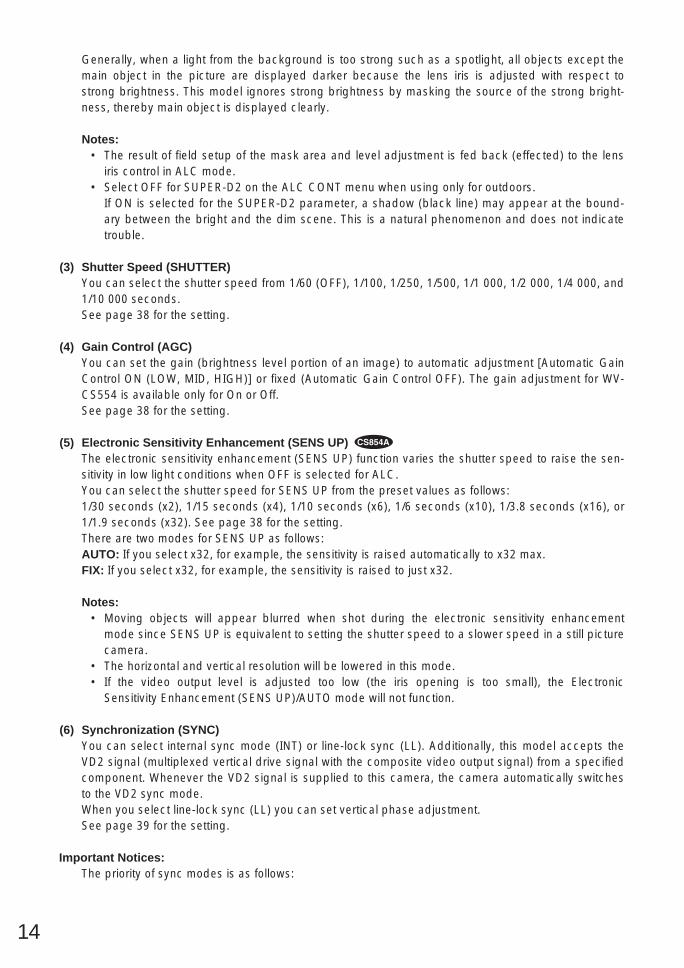
Generally, when a light from the background is too strong such as a spotlight, all objects except themain object in the picture are displayed darker because the lens iris is adjusted with respect tostrong brightness. This model ignores strong brightness by masking the source of the strong bright-ness, thereby main object is displayed clearly.
Notes:• The result of field setup of the mask area and level adjustment is fed back (effected) to the lens
iris control in ALC mode.• Select OFF for SUPER-D2 on the ALC CONT menu when using only for outdoors.
If ON is selected for the SUPER-D2 parameter, a shadow (black line) may appear at the bound-ary between the bright and the dim scene. This is a natural phenomenon and does not indicatetrouble.
(3) Shutter Speed (SHUTTER)You can select the shutter speed from 1/60 (OFF), 1/100, 1/250, 1/500, 1/1 000, 1/2 000, 1/4 000, and1/10 000 seconds.See page 38 for the setting.
(4) Gain Control (AGC)You can set the gain (brightness level portion of an image) to automatic adjustment [Automatic GainControl ON (LOW, MID, HIGH)] or fixed (Automatic Gain Control OFF). The gain adjustment for WV-CS554 is available only for On or Off.See page 38 for the setting.
(5) Electronic Sensitivity Enhancement (SENS UP) The electronic sensitivity enhancement (SENS UP) function varies the shutter speed to raise the sen-sitivity in low light conditions when OFF is selected for ALC.You can select the shutter speed for SENS UP from the preset values as follows:1/30 seconds (x2), 1/15 seconds (x4), 1/10 seconds (x6), 1/6 seconds (x10), 1/3.8 seconds (x16), or1/1.9 seconds (x32). See page 38 for the setting.There are two modes for SENS UP as follows:AUTO: If you select x32, for example, the sensitivity is raised automatically to x32 max.FIX: If you select x32, for example, the sensitivity is raised to just x32.
Notes:• Moving objects will appear blurred when shot during the electronic sensitivity enhancement
mode since SENS UP is equivalent to setting the shutter speed to a slower speed in a still picturecamera.
• The horizontal and vertical resolution will be lowered in this mode.• If the video output level is adjusted too low (the iris opening is too small), the Electronic
Sensitivity Enhancement (SENS UP)/AUTO mode will not function.
(6) Synchronization (SYNC)You can select internal sync mode (INT) or line-lock sync (LL). Additionally, this model accepts theVD2 signal (multiplexed vertical drive signal with the composite video output signal) from a specifiedcomponent. Whenever the VD2 signal is supplied to this camera, the camera automatically switchesto the VD2 sync mode. When you select line-lock sync (LL) you can set vertical phase adjustment.See page 39 for the setting.
Important Notices:The priority of sync modes is as follows:

15
1. Multiplexed Vertical Drive (VD2) (Highest)2. Line-lock (LL)3. Internal Sync (INT) (Lowest)
Note: The priority of automatic sync mode is the same as shown above.
(7) White Balance (WHITE BAL)You can select one of two modes for white balance adjustment as follows:
• ATW (Auto Tracing White Balance)In this mode, the color temperature is monitored continuously and thereby white balance is set auto-matically. The color temperature range for the proper white balance is approximately 2 600 - 6 000K.Proper white balance may not be obtained under the following conditions:1. The color temperature is out of the 2 600 - 6 000K range.2. When the scene contains mostly high color temperature (bluish) objects, such as a blue sky.3. When the scene is dim.
In these cases, select the AWC mode.
• AWC (Automatic White Balance)In this mode, accurate white balance is obtained within a color temperature range of approx. 2 300 -10 000K. See page 41 for the setting.
(8) Motion Detector (MOTION DET) The Motion Detector detects the motion in the scene by monitoring changes in the brightness level.You can select the level of sensitivity for motion on the SET UP menu.When the camera detects the motion it supplies the alarm signal to the external equipment and stopsat its position for the preset DWELL time. See page 42 for the setting.
(9) Auto Focus (AF MODE)The camera adjusts the focus automatically to the best position by sensing sharpness in the centerarea of the picture. S, M and L stand for the breadth of the sensing area: Small, Middle and Large.See page 43 for details.MANUAL S, M, L: Auto-focus is activated when the AF key on the controller is pressed.AUTO S, M, L: Auto-focus is activated automatically while operating manually (WV-CS854A): pan, tilt
or zoom. Auto-focus is activated automatically after a manual operation (WV-CS554).Note: If SENS UP is set to ON except x2 FIX or x2 AUTO setting, AUTO (S/M/L) is disabled and
MANUAL (S/M/L) is automatically selected.
(10)Special 2 Menu (SPECIAL 2) or Special Menu (SPECIAL) This menu allows you to adjust the following items: chroma level, aperture level, pedestal level, chro-ma phase (hue), and up side down. You can also reset your parameters to the values preset at thefactory. See page 44 for the setting.
RS485 CommunicationCommunication parameters
• Full/Half duplex (page 51)• Transmission speed (2 400 - 19 200 bps) (page 47)• Parity bit, Stop bit, Flow control (page 47)• Wait time, Delay time, Alarm output (page 47)• Camera units (96 units max.) (page 49)• Termination ON/OFF (page 51)• Reset parameters (page 48)

16
SETTING PROCEDURESThe following setting procedures are described on the assumption that this model is used in combinationwith the WJ-SX550B Matrix Switcher and WV-CU550B System Controller. In case of using a controllerother than the WV-CU550B, refer to the table on page 10.
Menu Display Setup Menu Display
WV-CU550B1. Select the number of the camera you want to set up and a monitor
to display the SET UP MENU.2. Display the D4 menu on the LCD by pressing the appropriate cur-
sor buttons.3. Press the F1 button.
The SET UP MENU appears on the monitor.4. To close the SET UP MENU, press the F4 button.
WV-CU360Press the CAM SETUP key for 2 seconds or more to open theSETUP menu.
WV-CU161Press the CAMERA SETUP key for 2 seconds or more to open theSETUP menu.
WV-RM701. Turn the MODE SELECTION switch to the NORMAL or ALARM
OFF position.2. Press the PROG switch for 2 seconds or more to open the
Program menu.3. Move the cursor to Camera Set Up, then press the SET switch to
open the SETUP menu.
D4 menu
F1
F1 F2 F3 F4
Camera Set Up Menu Res A.Res Exit
F2 F3 F4
Camera Set Up Menu On Exit
** RS485 SET UP ** UNIT NUMBERSUB ADDRESS BAUD RATEDATA BITPARITY CHECKSTOP BITXON/XOFFWAIT TIMEALARM DATADELAY TIMERET
11192008NONE1NOT USEOFFAUTO2OFF
Submenu(for RS485 setup)
** SET UP MENU **PRESET 1 MAP HOME POSITION SELF RETURN AUTO MODE AUTO PAN KEY DIGITAL FLIP LOCAL/REMOTE SPECIAL1CAMERARS485 SET UP
OFFOFFOFFAUTO PANONLOCAL
Setup menu
** SET UP MENU **PRESET 1 MAP HOME POSITION SELF RETURN AUTO MODE AUTO PAN KEY LOCAL/REMOTE PATROL CLEANINGCAMERA
OFFOFFOFFAUTO PANLOCALSTOPOFF
Setup menu
Submenu DisplayThe items marked can be selected/changed on the submenu.
• Move the cursor to an item with the mark and press the CAM(SET) key. The submenu is displayed.
17
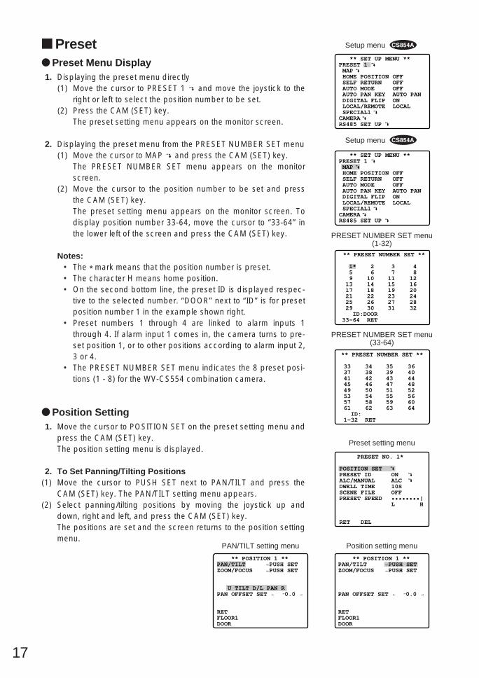
Preset Preset Menu Display1. Displaying the preset menu directly
(1) Move the cursor to PRESET 1 and move the joystick to theright or left to select the position number to be set.
(2) Press the CAM (SET) key.The preset setting menu appears on the monitor screen.
2. Displaying the preset menu from the PRESET NUMBER SET menu(1) Move the cursor to MAP and press the CAM (SET) key.
The PRESET NUMBER SET menu appears on the monitorscreen.
(2) Move the cursor to the position number to be set and pressthe CAM (SET) key.The preset setting menu appears on the monitor screen. Todisplay position number 33-64, move the cursor to “33-64” inthe lower left of the screen and press the CAM (SET) key.
Notes:• The * mark means that the position number is preset.• The character H means home position.• On the second bottom line, the preset ID is displayed respec-
tive to the selected number. “DOOR” next to “ID” is for presetposition number 1 in the example shown right.
• Preset numbers 1 through 4 are linked to alarm inputs 1through 4. If alarm input 1 comes in, the camera turns to pre-set position 1, or to other positions according to alarm input 2,3 or 4.
• The PRESET NUMBER SET menu indicates the 8 preset posi-tions (1 - 8) for the WV-CS554 combination camera.
** SET UP MENU **PRESET 1 MAP HOME POSITION SELF RETURN AUTO MODE AUTO PAN KEY DIGITAL FLIP LOCAL/REMOTE SPECIAL1CAMERARS485 SET UP
OFFOFFOFFAUTO PANONLOCAL
** PRESET NUMBER SET **
2 6 10 14 18 22 26 30
1* 5 9 13 17 21 25 29 ID:DOOR33-64 RET
3 7 11 15 19 23 27 31
4 8 12 16 20 24 28 32
PRESET NUMBER SET menu(1-32)
** PRESET NUMBER SET **
34 38 42 46 50 54 58 62
33 37 41 45 49 53 57 61 ID: 1-32 RET
35 39 43 47 51 55 59 63
36 40 44 48 52 56 60 64
PRESET NUMBER SET menu(33-64)
Position Setting1. Move the cursor to POSITION SET on the preset setting menu and
press the CAM (SET) key.The position setting menu is displayed.
2. To Set Panning/Tilting Positions(1) Move the cursor to PUSH SET next to PAN/TILT and press the
CAM (SET) key. The PAN/TILT setting menu appears.(2) Select panning/tilting positions by moving the joystick up and
down, right and left, and press the CAM (SET) key.The positions are set and the screen returns to the position settingmenu.
PRESET NO. 1*
POSITION SETPRESET IDALC/MANUALDWELL TIMESCENE FILEPRESET SPEED
RET DEL
ON ALC 10SOFF ••••••••|L H
Preset setting menu
→PUSH SET→PUSH SET
** POSITION 1 **PAN/TILTZOOM/FOCUS
PAN OFFSET SET ← −0.0 →
RETFLOOR1DOOR
Position setting menu
→PUSH SET→PUSH SET
** POSITION 1 **PAN/TILTZOOM/FOCUS
U TILT D/L PAN RPAN OFFSET SET ← −0.0 →
RETFLOOR1DOOR
** SET UP MENU **PRESET 1 MAP HOME POSITION SELF RETURN AUTO MODE AUTO PAN KEY DIGITAL FLIP LOCAL/REMOTE SPECIAL1CAMERARS485 SET UP
OFFOFFOFFAUTO PANONLOCAL
Setup menu
PAN/TILT setting menu
Setup menu

18
3. Pan OffsetIf the camera is replaced with a new one, Pan Offset is used toadjust its positions to be the same as before except patrol setting.The controller can be downloaded or uploaded the camera presetposition data.Caution: The preset data for conventional camera (WV-CS654 for
example) is incompatible with WV-CS854A’s. WV-CS854A’spreset data will be destroyed if you upload the conventionaldata. When this happened, prepare a WV-CS854A having theinitial factory settings. Download the factory settings into thecontroller and then upload to the camera whose data isdestroyed.
(1) Display the PRESET NUMBER SET menu.(2) Select a position number for the picture to be most enlarged
among the numbers by moving the joystick. Then press theCAM (SET) key. POSITION setting menu appears.
(3) Move the cursor to PAN OFFSET SET and select the right orleft arrow by moving the joystick.
(4) Press the CAM (SET) key until the desired offset value indegree appears.
(5) Move the cursor to other than PAN OFFSET, then press theMON (ESC) key.
Notes:• Further adjustment of the other positions is unnecessary. This
adjustment applies to all other positions.• Make sure to move the cursor before pressing the key in step
5. Otherwise the settings will be ignored.• Retry when the camera fails to upload or download the data.
4. To Set the Lens Zoom and Focus Positions(1) Move the cursor to PUSH SET next to ZOOM/FOCUS and
press the CAM (SET) key. The ZOOM/FOCUS setting menuappears.
(2) Select a zoom position by moving the zoom control up anddown, and a focus position by moving the focus control upand down, and then press the CAM (SET) key.The positions are set and the screen returns to the positionsetting menu.
Notes:• When the camera is used at a nearly horizontal angle, the
focus may not be adjustable to a high level of accuracy.• If you move the cursor to POSITION number and move the
joystick right or left, the position number can be selected. The selected preset position number can also be set afterpressing the CAM (SET) key.
• The preset and camera IDs appear at the lower-left corner ofthe position setting menu after setting them.
5. Move the cursor to RET and press the CAM (SET) key to return tothe preset setting menu.
→PUSH SET→PUSH SET
** POSITION 1 **PAN/TILTZOOM/FOCUS
PAN OFFSET SET ← −0.0 →
RETFLOOR1DOOR
Position setting menu
** POSITION 1 **PAN/TILTZOOM/FOCUS
U ZOOM D/L FOCUS RPAN OFFSET SET ← −0.0 →
RETFLOOR1DOOR
→PUSH SET→PUSH SET
→PUSH SET→PUSH SET
** POSITION 1 **PAN/TILTZOOM/FOCUS
PAN OFFSET SET ← −0.0 →
RETFLOOR1DOOR
Position setting menu
** PRESET NUMBER SET **
2 6 10 14 18 22 26 30
1* 5 9 13 17 21 25 29 ID:DOOR33-64 RET
3 7 11 15 19 23 27 31
4 8 12 16 20 24 28 32
PRESET NUMBER SET menu(1-32)
→PUSH SET→PUSH SET
** POSITION 1 **PAN/TILTZOOM/FOCUS
PAN OFFSET SET ← −0.0 →
RETFLOOR1DOOR
Position setting menu
ZOOM/FOCUS setting menu

19
Preset ID Setting1. Move the cursor to PRESET ID on the preset setting menu and
select ON or OFF by moving the joystick to the right or left.ON: Preset ID is displayed on the screen.OFF: Preset ID is not displayed.
2. Press the CAM (SET ) key to display the preset ID setting menu.
To Enter a New PRESET ID1. Move the cursor to the desired character using the joystick,
and press the CAM (SET) key.2. The selected character appears in the editing area. (The
pointer in the editing area moves to the right automatically atthis moment.) To enter a blank, select SPACE.
3. Repeat the above procedure until all characters areentered.
Command
EditingArea
CharacterArea
Pointer
Character Cursor
PRESET NO. 1* 0123456789 ABCDEFGHIJKLM NOPQRSTUVWXYZ ().,'":;&#!?= +-*/%$
SPACE COPY POSI RET RESET
DOOR............
Preset ID setting menu
To Copy a Preset ID from Another Position1. Move the cursor to COPY and press the CAM (SET) key. The
preset ID in the preceding position is immediately shown.Each consecutive pressing of the CAM (SET) key displays theID preceding the one currently displayed.
2. Display the most prospective ID.3. Follow the step “To change an entered PRESET ID” if neces-
sary.
To Change an Entered PRESET ID1. Move the pointer to the character to be edited in the editing
area by using the joystick, and press the CAM (SET) key.2. Select a new character by using the joystick.3. Press the CAM (SET) key to determine the PRESET ID.
PRESET NO. 1* 0123456789 ABCDEFGHIJKLM NOPQRSTUVWXYZ ().,'":;&#!?= +-*/%$
SPACE COPY POSI RET RESET
DOOR............
PRESET NO. 1* 0123456789 ABCDEFGHIJKLM NOPQRSTUVWXYZ ().,'":;&#!?= +-*/%$
SPACE COPY POSI RET RESET
DOOR............
To Delete an Entered PRESET IDMove the cursor to RESET and press the CAM (SET) key.
PRESET NO. 1* 0123456789 ABCDEFGHIJKLM NOPQRSTUVWXYZ ().,'":;&#!?= +-*/%$
SPACE COPY POSI RET RESET
DOOR............
PRESET NO. 1*
POSITION SETPRESET IDALC/MANUALDWELL TIMESCENE FILEPRESET SPEED
RET DEL
ON ALC 10SOFF••••••••|L H
Preset setting menu

20
To Set a Display Position for a PRESET ID1. Move the cursor to POSI and press the CAM (SET) key. The
display position set menu appears.2. Using the joystick, move the ID to the desired position on the
screen, then press the MON (ESC) key. The display positionis set and the screen returns to the PRESET ID setting menu.
PRESET NO. 1* 0123456789 ABCDEFGHIJKLM NOPQRSTUVWXYZ ().,'":;&#!?= +-*/%$
SPACE COPY POSI RET RESET
DOOR............
FLOOR 1DOOR
PRESET NO. 1* 0123456789 ABCDEFGHIJKLM NOPQRSTUVWXYZ ().,'":;&#!?= +-*/%$
SPACE COPY POSI RET RESET
DOOR............
Display position set menu
To Enter the Next ID without Returning to the Preset SettingMenu1. With the preset ID setting menu, move the cursor to the top
line and select the desired position number by moving thejoystick to the right or left.
2. Enter, copy, change or delete the ID as described above.
To Return to the Preset Setting MenuMove the cursor to RET and press the CAM (SET) key.
Light Control Setting1. Move the cursor to ALC/MANUAL and select ALC or MANUAL by
moving the joystick to the right or left.ALC: The lens iris is automatically adjusted to suit the brightness
of the object.MANUAL: The lens iris is fixed at the set value regardless of the
brightness of the object.
2. In case of ALC Press the CAM (SET) key. The backlight compensation menuappears in the display. See page 36 for the setting.
3. In case of MANUAL Press the CAM (SET) key. The setting menu appears in the dis-play. Set the lens iris level as desired by moving the joystick to theright or left.
PRESET NO. 1*
POSITION SETPRESET IDALC/MANUALDWELL TIMESCENE FILEPRESET SPEED
RET DEL
ON ALC 10SOFF ••••••••|L H
Preset setting menu
** MANUAL CONT **
IRIS
RET
••••|••••CLOSE OPEN
Manual setting menu

21
** SCENE FILE 1 **
SHUTTERAGCSENS UPWHITE BALMOTION DETAF MODE
RET
OFFON(MID)OFFATWOFFMANUAL M
Scene file setting menu
** SCENE FILE 1 **
SHUTTERAGCWHITE BALAF MODE
RET
OFFONATWMANUAL M
Scene file setting menu
PRESET NO. 1*
POSITION SETPRESET IDALC/MANUALDWELL TIMESCENE FILEPRESET SPEED
RET DEL
ON ALC 10S1 ••••••••|L H
Preset setting menu
** PRESET NUMBER SET **
2 6 10 14 18 22 26 30
1* 5 9 13 17 21 25 29 ID:DOOR33-64 RET
3 7 11 15 19 23 27 31
4 8 12 16 20 24 28 32
PRESET NUMBER SET menu
PRESET NO. 1*
POSITION SETPRESET IDALC/MANUALDWELL TIMESCENE FILEPRESET SPEED
RET DEL
ON ALC 10SOFF••••••••|L H
Preset setting menu
Dwell Time Setting• Move the cursor to DWELL TIME and set a dwell time by moving
the joystick to the right or left. Dwell time changes as follows:
The letter S stands for second(s), and MIN stands for minute(s).
Scene File Setting1. To set a scene file number
Move the cursor to SCENE FILE and select a scene file number (1to 10, or OFF) by moving the joystick to the right or left. No scenefile is selected at OFF.
2. To set scene file detailsMove the cursor to a scene file number and press the CAM (SET)key. The setting menu appears.See the pages below for the setting.
Shutter speed: page 38AGC: page 38Electronic sensitivity enhancement: page 38White balance: page 40Motion detector: page 42Auto focus: page 43
Preset Speed• Move the cursor to PRESET SPEED and select a speed by moving
the joystick to the right or left.
To Return to the PRESET NUMBER SET Menu• Move the cursor to RET and press the CAM (SET) key. The PRE-
SET NUMBER SET menu appears with the * mark on the right ofthe preset position number.
To Return to the Setup Menu• Move the cursor to RET and press the CAM (SET) key.
PRESET NO. 1*
POSITION SETPRESET IDALC/MANUALDWELL TIMESCENE FILEPRESET SPEED
RET DEL
ON ALC 10SOFF••••••••|L H
Preset setting menu
2S 3S 5S 10S 30S 1MIN 2MIN 3MIN 4MIN

22
PRESET NO. 1*
POSITION SETPRESET IDALC/MANUALDWELL TIMESCENE FILEPRESET SPEED
RET DEL
ON ALC 10SOFF••••••••|L H
Preset setting menu
Deleting Preset Positions1. Move the cursor to PRESET 1 and select the position number to
be deleted by moving the joystick.
2. Press the CAM (SET) key to display the preset setting menu.
3. Move the cursor to DEL and press the CAM (SET) key.This deletes the preset position and the PRESET NUMBER SETmenu appears. The * mark on the right of the number disappears.Note: Your selected preset number is canceled only in SEQ and
SORT mode. The previous set parameters (for PAN, TILTpositions, etc.) are not changed. If you want to change theseparameters, you must set them again.
** SET UP MENU **PRESET 1 MAP HOME POSITION SELF RETURN AUTO MODE AUTO PAN KEY DIGITAL FLIP LOCAL/REMOTE SPECIAL1CAMERARS485 SET UP
OFFOFFOFFAUTO PANONLOCAL
Setup menu
Home Position Setting1. To set a position number for the home position
Move the cursor to HOME POSITION and select the desired posi-tion number by moving the joystick to the right or left.
2. Select OFF if you are not using the home position function.Note: This setting functions only when AUTO MODE is set to OFF.
** PRESET NUMBER SET **
2 6 10 14 18 22 26 30
1* 5 9 13 17 21 25 29 ID:DOOR33-64 RET
3 7 11 15 19 23 27 31
4 8 12 16 20 24 28 32
** PRESET NUMBER SET **
2 6
1* 5
ID:DOORRET
3 7
4 8
PRESET NUMBER SET menu
** SET UP MENU **PRESET 1 MAP HOME POSITION SELF RETURN AUTO MODE AUTO PAN KEY DIGITAL FLIP LOCAL/REMOTE SPECIAL1CAMERARS485 SET UP
15OFFOFFAUTO PANONLOCAL
Setup menu
Self Return Setting• To set a time-out parameter for return to the home position
Move the cursor to SELF RETURN and select a return time bymoving the joystick to the right or left. Return time changes as fol-lows:
** SET UP MENU **PRESET 1 MAP HOME POSITION SELF RETURN AUTO MODE AUTO PAN KEY DIGITAL FLIP LOCAL/REMOTE SPECIAL1CAMERARS485 SET UP
OFF10MINOFFAUTO PANONLOCAL
Setup menu2MIN 3MIN 5MIN 10MIN
60MIN 30MIN 20MIN
1MIN
OFF
MIN stands for minute(s).
Note: The camera will return to the AUTO MODE if that is set toSEQ, SORT, AUTO PAN or PATROL when a specific time haselapsed after a manual operation.
PRESET NUMBER SET menu

23
Auto Mode SelectionThe menu screens follow the example for WV-CS854A.1. To set auto mode
Move the cursor to AUTO MODE and select a mode by movingthe joystick to the right or left. Modes change as follows:
** SET UP MENU **PRESET 1 MAP HOME POSITION SELF RETURN AUTO MODE AUTO PAN KEY DIGITAL FLIP LOCAL/REMOTE SPECIAL1CAMERARS485 SET UP
OFFOFFAUTO PANAUTO PANONLOCAL
Setup menu
2. When AUTO PAN is selected, set details as follows:Move the cursor to AUTO PAN and press the CAM (SET) key todisplay the AUTO PAN setting menu.
3. To set a panning start position and panning end positionFollow the steps below.(1) Move the cursor to POSITION SET and press the CAM (SET)
key.The cursor moves to START.
(2) Move the joystick to the right or left to select a panning startposition and press the CAM (SET) key.This determines the start position and the cursor moves toEND.
(3) Move the joystick to the right or left to select a panning endposition and press the CAM (SET) key.This determines the end position and the cursor moves toPOSITION SET.
4. To set a panning speedMove the cursor to SPEED, and move the joystick to the right orleft to set a panning speed.The panning speed increases when the joystick is moved to theright, and decreases when it is moved to the left.
Caution: If the panning range is changed after the camera hasnot panned for a long time or has been panning in the samepanning range, the picture may not be clear or noise mayappear. In this case, pan the camera fully several times. If thisdoes not eliminate the problem, refer servicing to qualifiedservice personnel.
5. To set pan limit ON/OFFMove the cursor to PAN LIMIT and select ON or OFF by movingthe joystick to the right or left.ON: Manual pan is limited from the start point to the end point
specified by POSITION SET. Set endless turn to OFF beforepan limit is set to ON.
OFF: Manual pan is not limited.
Note: When ON is set, manual pan moves the camera away fromthe other side of the start-end range.
** AUTO PAN **
POSITION SET
SPEED
PAN LIMITENDLESSDWELL TIME
RET
STARTEND••••|••••L HOFFOFF1S
AUTO PAN setting menu
** AUTO PAN **
POSITION SET
SPEED
PAN LIMITENDLESSDWELL TIME
RET
STARTEND••••|••••L HOFFOFF1S
** AUTO PAN **
POSITION SET
SPEED
PAN LIMITENDLESSDWELL TIME
RET
STARTEND••••|••••L HOFFOFF1S
** AUTO PAN **
POSITION SET
SPEED
PAN LIMITENDLESSDWELL TIME
RET
STARTEND••••|••••L HOFFOFF1S
OFF SEQ SORT AUTO PAN PATROL
OFF SEQ SORT AUTO PAN

24
6. To set endless turn ON/OFFMove the cursor to ENDLESS, and move the joystick to the right orleft to set endless turn ON or OFF.ON: The camera pans from the start position to the end position,
then keeps rotating in the same direction to return to the startposition. Set pan limit to OFF before endless turn is set to ON.
OFF: The camera pans from the start position to the end position,then rotates backward to the start position.This movement is repeated over and over.
7. To set a dwell timeMove the cursor to DWELL TIME and select a dwell time by mov-ing the joystick to the right or left. Dwell time changes as follows:
** AUTO PAN **
POSITION SET
SPEED
PAN LIMITENDLESSDWELL TIME
RET
STARTEND••••|••••L HOFFON1S
** AUTO PAN **
POSITION SET
SPEED
PAN LIMITENDLESSDWELL TIME
RET
STARTEND••••|••••L HOFFOFF1S0S 1S 2S 3S
30S 5S10S20S
Notes:• When the panning, tilting, zooming or focusing in SEQ, SORT
or PATROL (only for WV-CS854A) mode operation is con-trolled manually, the Auto mode function should be canceled.To activate Auto mode, select the desired AUTO MODE againor set a time for SELF RETURN in the SET UP menu to resumethe AUTO MODE after the time set.
• When 0S is selected, the camera stops without dwelling andstarts.
• Auto refreshing may be activated during PATROL PLAY orAUTO MODE to calibrate the lens position.
AUTO PAN KEY SettingThis is to assign one of following auto function to the AUTO key on thecontroller. Pressing the AUTO key activates the assigned functionafter this setting. The menu screen follows the example for WV-CS854A.
• Move the cursor to AUTO PAN KEY and select an auto function bymoving the joystick to the right or left.Mode changes as follows:
AUTO PAN: assigns auto panning function to the key.SEQ: assigns SEQUENCE function to the key.SORT: assigns SORT function to the keyPATROL: assigns PATROL PLAY function to the key.Note: AUTO PAN LED on the controller does not light if someting
other than AUTO PAN is assigned. AUTO PAN does not stopwith the AUTO PAN key.
** SET UP MENU **PRESET 1 MAP HOME POSITION SELF RETURN AUTO MODE AUTO PAN KEY DIGITAL FLIP LOCAL/REMOTE SPECIAL1CAMERARS485 SET UP
OFFOFFOFFAUTO PANONLOCAL
Setup menu
SEQ SORT AUTO PAN
PATROL

25
** SPECIAL 1 **PRIVACY ZONE OFF(ENB)PROPO.P/T ONAREA TITLE ON(USER)PATROL STOPALARM IN/OUTPASSWORD LOCK OFFCLEANING OFFEL-ZOOM ONPRESET ALM OFFIMAGE HOLD OFFRET
Special 1 menu
** ZONE NUMBER 1*/8 **
RET
ZONE NUMBER setting menu
** SET UP MENU **PRESET 1 MAP HOME POSITION SELF RETURN AUTO MODE AUTO PAN KEY DIGITAL FLIP LOCAL/REMOTE SPECIAL1CAMERARS485 SET UP
OFFOFFOFFAUTO PANONLOCAL
Setup menu
DIGITAL FLIP ON/OFF• Move the cursor to DIGITAL FLIP and select ON or OFF by mov-
ing the joystick to the right or left.OFF: Tilt range is limited from 0° to 90°.ON: The digital flip function allows the tilt angle to widen up to
180°. The image on the monitor screen is flipped horizontallyand vertically at the tilt angle of approx. 135°. (If the camerais installed on a ceiling).
Note: Tilt range narrows from 180° to 90° if PAN LIMIT is set toON.
Notes:• Digital flip functions while moving the joystick downwards. In case
of moving the joystick to other directions, it does not function.• When OFF is selected for DIGITAL FLIP, the following operations
are required to move the camera 180° vertically.1) Move the joystick downwards and the camera will aim below.2) Move the joystick to the right or left and the camera will rotate
180° horizontally.3) Move the joystick upwards.
• To set preset position directly from the WV-CU360 controller, it ismomentary required setting the electronic zoom function and digi-tal flip function to OFF. Tilt range setting is disabled between 90° and 180°.
LOCAL/REMOTE Setting• Move the cursor to LOCAL/REMOTE, and move the joystick to the
right or left.You can toggle between LOCAL and REMOTE.Note: REMOTE does not work when the WV-RM70, WV-CU360,
WV-CU161, WJ-FS616, WJ-SX550B or WJ-SX850 is connect-ed. Make sure that LOCAL is selected in this case.
SPECIAL 1 Privacy Zone ON/OFF (PRIVACY ZONE)Up to 8 unwanted zones can be masked on the monitor screen.
1. Move the cursor to PRIVACY ZONE and then select ON (ENB) orOFF (ENB) by moving the joystick to the right or left. Press theCAM (SET) key to display the ZONE NUMBER selection menu.
ON (ENB): Preset privacy zones are veiled on the monitor screen.OFF (ENB): Veil function does not work.
Note: If (DIS) follows, instead of (ENB), after ON or OFF, step 2onward are not applicable. Select OFF for PASSWORD LOCKto take the following steps.
** SET UP MENU **PRESET 1 MAP HOME POSITION SELF RETURN AUTO MODE AUTO PAN KEY DIGITAL FLIP LOCAL/REMOTE SPECIAL1CAMERARS485 SET UP
OFFOFFOFFAUTO PANONLOCAL
Setup menu

26
** ZONE NUMBER 3*/8 ** PAN/TILT →PUSH SET ZOOM/FOCUS →PUSH SET U TILT D/L PAN R
ZONE SCALE ••••|•••• SET DEL L HRET
PAN/TILT setting menu
** ZONE NUMBER 3*/8 ** PAN/TILT →PUSH SET ZOOM/FOCUS →PUSH SET
ZONE SCALE ••••|•••• SET DEL L HRET
ZONE setting menu
2. Select a zone number by moving the joystick to the right or left,then press the CAM (SET) key.
• A zone number followed by * (asterisk) indicates that the zone hasalready been registered.
• When a zone number having no * is selected, the picture iszoomed out fully.
• When a registered zone number is selected, the camera moves tothe preset position. Note that if you move any of PAN/TILT,ZOOM/FOCUS or ZONE SCALE in that position, the registeredzone number having no * is canceled.
• Zone frame appears in the center of the screen if 3 or fewer maskareas exist in that picture and if the zone number is not registeredyet.
• The privacy zone setting may appear on the monitor dependingon the direction of the camera.
• Privacy zone function will not work at start-up immediately afterturning power on.
3. To register a new zone3-1 Move the cursor to PUSH SET on the PAN/TILT line, then
press the CAM (SET) key.
3-2 Move the joystick to adjust the pan and tilt position so that thedesired position comes into the zone frame.
Note: Zone setting is not available while the zone frame disap-pears, for example the camera directs further downward fromthe 45° position.
3-3 Move the cursor to PUSH SET on the ZOOM/FOCUS, thenpress the CAM (SET) key.
3-4 Adjust zoom and focus, then press the CAM (SET) key.Zoom can be adjusted within the range of 1 to 10 magnifica-tions.
3-5 Move the cursor to ZONE SCALE, and move the joystick tothe right or left to adjust the zone frame. Press the CAM (SET)key after the adjustment.Moving the joystick in the L direction decreases the zoneframe, and moving it in the H direction increases it. However,the aspect ratio is fixed at 3 to 4.The privacy zone setting has been completed.The menu returns to the ZONE NUMBER setting menu. If DELis selected, zone setting is released and the ZONE NUMBERsetting menu appears.
** ZONE NUMBER 3*/8 ** PAN/TILT →PUSH SET ZOOM/FOCUS →PUSH SET
ZONE SCALE ••••|•••• SET DEL L HRET
ZONE SCALE setting menu
** ZONE NUMBER 3*/8 ** PAN/TILT →PUSH SET ZOOM/FOCUS →PUSH SET U ZOOM D/L FOCUS R
ZONE SCALE ••••|•••• SET DEL L HRET
ZOOM/FOCUS setting menu
** ZONE NUMBER 1*/8 ** PAN/TILT →PUSH SET ZOOM/FOCUS →PUSH SET
ZONE SCALE ••••|•••• SET DEL L HRET
ZONE setting menu

27
3-6• To complete new settings and repeat another setting, move the cursor to SET and press the CAM
(SET) key. The ZONE NUMBER Selection menu returns.• To cancel new settings and return to SPECIAL 1 MENU, move the cursor to DEL and press the
CAM (SET) key. New settings are not registered.• To complete new settings and return to SPECIAL 1 MENU, move the cursor to RET and press the
CAM (SET) key.
Proportional Pan/Tilt (PROPO. P/T) • Move the cursor to PROPO. P/T and select either ON or OFF by
moving the joystick to the right or left.Default : ON
ON: Pan/tilt speed is in inverse proportion to the zoom ratio as fol-lows:
Zoom ratio Speed levelx1 8 (the fastest) x2 5 x4 3 x8 1 x15 or more 0 (the slowest)
* The speed level values are approximate.
OFF: The speed is constant at the fastest level on the communi-cation command regardless of the zoom ratio.
Area Title (AREA TITLE) Up to 8 area titles can be added in specific positions.
1. Select ON (NESW), ON (USER) or OFF by moving the joystick tothe right or left.ON (NESW): An area title is displayed indicating the camera
direction: North (N), North-East (NE), East (E), South-East(SE), South (S), South-West (SW), West (W) and North-West(NW).
ON (USER): A user customized area title is displayed with a maxi-mum of 16 characters.
OFF: Area tittle is not displayed.Default : ON (USER)
2. Press the CAM (SET) key. A submenu appears except when OFFis selected.
Settings for ON (NESW)1. Move the cursor to PUSH SET on the PAN/TILT line, then press
the CAM (SET) key. PAN/TILT is highlighted and “U TILT D/L PANR” appears.
2. Move the joystick to turn the camera north, then press the CAM(SET) key. The origin of the direction (North) is set.
** SPECIAL 1 **PRIVACY ZONE OFF(ENB)PROPO.P/T ONAREA TITLE ON(USER)PATROL STOPALARM IN/OUTPASSWORD LOCK OFFCLEANING OFFEL-ZOOM ONPRESET ALM OFFIMAGE HOLD OFFRET
Special 1 menu
** SPECIAL 1 **PRIVACY ZONE OFF(ENB)PROPO.P/T ONAREA TITLE ON(NESW)PATROL STOPALARM IN/OUTPASSWORD LOCK OFFCLEANING OFFEL-ZOOM ONPRESET ALM OFFIMAGE HOLD OFFRET
Special 1 menu
PUSH SETPUSH SET
** DIRECTION(NESW) **PAN/TILTZOOM/FOCUSPOSI
+ N
RET
p
p
AREA TITLE (NESW) setting menu
PUSH SETPUSH SET
** DIRECTION(NESW) **PAN/TILTZOOM/FOCUSPOSI U TILT D/L PAN R
+ N
RET
p
p
PAN/TILT setting menu

28
Note: Area titles appear in reverse video until the origin is set.
3. Move the cursor to PUSH SET on the ZOOM/FOCUS line, thenpress the CAM (SET) key. ZOOM/FOCUS is highlighted and “UZOOM D/L FOCUS R” appears.
4. Move the joystick to adjust the zoom or focus.
5. Move the cursor to POSI , then press the CAM (SET) key. Thedisplay position of the area title appears on the monitor. If need-ed, change the display position by moving the joystick, then pressthe MON (ESC) key.An area title is always displayed under the camera ID.If the camera ID and an area title are set to be shown in separatepositions, the area title display position has priority over the cam-era ID setting.
6. Move the cursor to RET, then press the CAM (SET) key. SPECIAL1 menu appears again.
Setting [ON (USER)]If ON (USER) is selected on the SPECIAL 1 menu, the Area Titleselection menu appears. The screen has the number column andtitle column above RET and RESET.
Note: The area numbers followed by an asterisk * have alreadypreset.
1. To select a camera direction, move the cursor to the desired num-ber, then press the CAM (SET) key. The direction menu of theselected number appears.
2. Adjust PAN/TILT, ZOOM/FOCUS and display position in the assame way as AREA TITLE, DIRECTION (NESW). See page 27.
3. To add a user-customized title, move the cursor to the title of thedesired number, then press the CAM (SET) key. AREA TITLEmenu of the selected number appears.
AREA TITLE Editing1. Move the cursor to the desired character in the character field
using the joystick then press the CAM (SET) key.2. The selected character appears in the editing field and the blink-
ing cursor moves one position to the right.3. Repeat steps 1 and 2 until one area title is completed.4. Move the cursor to POSI , then press the CAM (SET) key. The
display position of the area title appears on the monitor. If need-ed, change the display position by moving the joystick, then pressthe MON (ESC) key.
PUSH SETPUSH SET
** DIRECTION(NESW) **PAN/TILTZOOM/FOCUSPOSI U ZOOM D/L FOCUS R
+ N
RET
p
p
ZOOM/FOCUS setting menu
FLOOR 1N
Display Position setting menu
PUSH SETPUSH SET
** DIRECTION(USER) 1 **PAN/TILTZOOM/FOCUS
+ NORTH
RET DEL
p
p
DIRECTION (USER) setting menu
** AREA TITLE(USER) ** 1* NORTH 2 3 EAST 4 SOUTH-EAST 5 SOUTH 6 SOUTH-WEST 7 8 NORTH-WEST
RET RESET
AREA TITLE (USER) selection menu
** SPECIAL 1 **PRIVACY ZONE OFF(ENB)PROPO.P/T ONAREA TITLE ON(USER)PATROL STOPALARM IN/OUTPASSWORD LOCK OFFCLEANING OFFEL-ZOOM ONPRESET ALM OFFIMAGE HOLD OFFRET
SPECIAL 1 menu
29
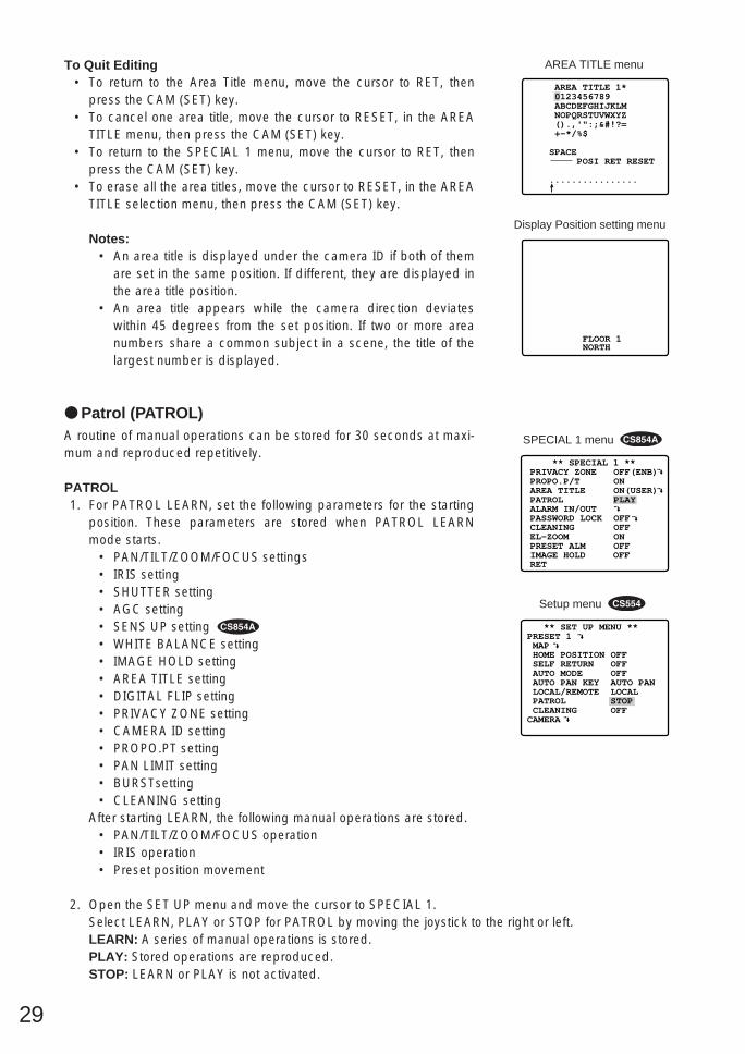
To Quit Editing• To return to the Area Title menu, move the cursor to RET, then
press the CAM (SET) key.• To cancel one area title, move the cursor to RESET, in the AREA
TITLE menu, then press the CAM (SET) key.• To return to the SPECIAL 1 menu, move the cursor to RET, then
press the CAM (SET) key.• To erase all the area titles, move the cursor to RESET, in the AREA
TITLE selection menu, then press the CAM (SET) key.
Notes:• An area title is displayed under the camera ID if both of them
are set in the same position. If different, they are displayed inthe area title position.
• An area title appears while the camera direction deviateswithin 45 degrees from the set position. If two or more areanumbers share a common subject in a scene, the title of thelargest number is displayed.
Patrol (PATROL)A routine of manual operations can be stored for 30 seconds at maxi-mum and reproduced repetitively.
PATROL1. For PATROL LEARN, set the following parameters for the starting
position. These parameters are stored when PATROL LEARNmode starts.
• PAN/TILT/ZOOM/FOCUS settings• IRIS setting• SHUTTER setting• AGC setting• SENS UP setting • WHITE BALANCE setting• IMAGE HOLD setting• AREA TITLE setting• DIGITAL FLIP setting• PRIVACY ZONE setting• CAMERA ID setting• PROPO.PT setting• PAN LIMIT setting• BURSTsetting• CLEANING setting
After starting LEARN, the following manual operations are stored.• PAN/TILT/ZOOM/FOCUS operation• IRIS operation• Preset position movement
2. Open the SET UP menu and move the cursor to SPECIAL 1.Select LEARN, PLAY or STOP for PATROL by moving the joystick to the right or left.LEARN: A series of manual operations is stored.PLAY: Stored operations are reproduced.STOP: LEARN or PLAY is not activated.
FLOOR 1NORTH
Display Position setting menu
** SPECIAL 1 **PRIVACY ZONEPROPO.P/TAREA TITLEPATROLALARM IN/OUTPASSWORD LOCKCLEANINGEL-ZOOMPRESET ALMIMAGE HOLD OFFRET
OFF(ENB) ON ON(USER) PLAY OFF OFF ON OFF
SPECIAL 1 menu
** SET UP MENU **PRESET 1 MAP HOME POSITION SELF RETURN AUTO MODE AUTO PAN KEY LOCAL/REMOTE PATROL CLEANINGCAMERA
OFFOFFOFFAUTO PANLOCALSTOPOFF
Setup menu
AREA TITLE 1* 0123456789 ABCDEFGHIJKLM NOPQRSTUVWXYZ ().,'":;&#!?= +-*/%$
SPACE POSI RET RESET
................
AREA TITLE menu

30
PATROL LEARN with a Controller Having PATROL Key1. Press the PATROL key and the CAM (SET) key simultaneously to
start PATROL LEARN. The setup menu changes to show “LEARN-ING” and the starting point parameters are stored.
2. Operate manually. Operations data is stored.3. To stop, press the PATROL STOP key.
PATROL LEARN with a Controller not Having PATROL Key1. Close the SET UP or SPECIAL 1 menu to start PATROL LEARN.
Starting point parameters are stored and “LEARNING” is dis-played on the monitor.
2. Operate manually.3. Open the SET UP menu to stop learning.
Notes:• It is recommended that you set PAN LIMIT to ON for PATROL LEARN. Otherwise PAN LIMIT is
invalid for playback.• Restart from the beginning if the power has failed during PATROL LEARN.• LEARN also stops 30 seconds after starting, or if the memory is full.• Auto refreshing may be activated during PATROL PLAY or AUTO MODE to calibrate the lens
position.
PATROL PLAY with a Controller Having PATROL Key1. Press the PATROL key. The camera turns to the starting point and the operations stored in the memo-
ry are reproduced. Iris operation only is accepted during playback.2. Press the PATROL STOP key to stop playback or press any manual operation key (e.g.,
PAN/TILT/ZOOM/FOCUS) except the iris keys.
PATROL PLAY with a Controller not Having PATROL Key1. Close the SET UP or SPECIAL 1 menu. The camera turns to the starting point and the operations
stored in the memory are reproduced. Iris operation only is accepted during playback.2. Open the SET UP menu, or press any manual operation key (e.g., PAN/TILT/ ZOOM/FOCUS) except
the iris keys to stop playback.
PATROL PLAY with AUTO PAN Key1. If the PATROL PLAY function is assigned to the AUTO PAN key, press the AUTO PAN key to turn the
camera back to the starting point and to reproduce the operation data stored in the memory.2. Press the PATROL STOP key or any manual operation key (e.g., PAN/TILT/ZOOM/FOCUS) except the
iris keys to stop playback.
Notes:• During PATROL PLAY, the camera movement may occasionally deviate from the entered routine
when the routine includes a move to a preset position. If this happens, re-enter the routine of manualoperations in PATROL LEARN.
• During PATROL PLAY, black and white automatic switching does not work.• During PATROL PLAY, when the power of the system controller is turned on or off, PATROL PLAY
stops. In case of this, press the PATROL PLAY key again. (If SELF RETURN is set, PATROL PLAY willstart again after elapsing the setting return time.)
LEARNING
PATROL LEARN

31
Alarm IN/OUT (ALARM IN/OUT)Move the cursor to ALARM IN/OUT, then press the CAM (SET) key.ALARM I/O submenu appears.
Note: While the camera is in AF mode or the lens moves betweenWIDE and TELE, alarm input may be ignored if several alarminputs are received in succession.
ALARM IN 1-4Alarm input signals are supplied from external devices throughthe ALARM IN connector to turn the camera to a preset position.
1. Move the cursor to ALARM IN 1* and select a preset position orOFF by moving the joystick, then press the CAM (SET) key.
* Set ALARM IN 2, 3 and 4 in the same way as ALARM IN 1.
1 POSI, 2 POSI, 3 POSI, 4 POSI: Preset position. If an alarm input is received, the camera turns to apreset position, then sends alarm output signal. Position number correspond to alarm input num-bers (1-1, 2-2, 3-3 and 4-4).
B/W: Available for ALARM INPUT 4 only. The camera changes its mode from color to black and whiteif ALARM IN 4 is supplied.
OFF: The camera ignores alarm inputs.
Note: If two or more alarm inputs are received while the camera is moving to a preset position, thecamera starts to aim at preset positions in small preset numerical order after current positioning.
CNT-CLS 1-2 (Output)Two contact closure signals (Open collector type) are output through the ALARM OUT connector.
1. Move the cursor to CNT-CLS 1, then select OFF, ALARM or AUX 1 by moving the joystick to the rightor left.When ALARM is selected, TIME OUT appears. Select an appropriate duration from among 100 MS,200 MS, 1000 MS (1 s), 2000 MS (2 s), 4000 MS (4 s) by moving the joystick to the right or left.
Note: The shorter the duration, the more frequent will be the detection output.
2. Move the cursor to CNT-CLS 2, then select OFF, B/W or AUX 2 by moving the joystick to the right orleft.OFF: Contact closure signals are inactivated.ALM: Available for CNT-CLS 1 only. Motion detection is output.AUX 1(2): An alarm signal is output when the camera receives a command from the controller.B/W: Available for CNT-CLS 2 only. ON (active) is output when the camera operates in black and
white mode if ALARM IN 4 is set to B/W.
Note: We recommend that you set the connected external device to ignore the shorter alarm outputsof 90 ms or less from the camera.
COAXIAL ALARM OUT Alarm output signals are supplied through the coaxial cable.
1. Move the cursor to COAX and select ON or OFF.
** ALARM IN/OUT **ALARM IN 1ALARM IN 2ALARM IN 3ALARM IN 4 CNT-CLS 1 TIME OUTCNT-CLS 2COAX ALM OUT
RET
OFF OFF OFF OFF OFF 100MS OFF OFF
ALARM I/O submenu
** SPECIAL 1 **PRIVACY ZONEPROPO.P/TAREA TITLEPATROLALARM IN/OUTPASSWORD LOCKCLEANINGEL-ZOOMPRESET ALMIMAGE HOLD OFFRET
OFF(ENB) ON ON(USER) STOP OFF OFF ON OFF
SPECIAL 1 menu

32
2. Press the CAM (SET) key.ON: The camera sends an alarm output signal via the coaxial cable after it turns to a preset position.OFF: The camera does not send the output signal.
Notes:• The camera ignores alarm inputs during manual operation.• Select OFF when the camera downloads or uploads the preset data.
Password Lock (PASSWORD LOCK) Caution: For security, do not operate your VCR for recording while the
password menus are displayed on the monitor.
A 3-digit number is used for a password to limit access to the privacyzone settings.
1. Move the cursor to PASSWORD LOCK, then select ON or OFF bymoving the joystick to the right or left.Note: ON or OFF can be changed only after going through the
password verification.
OFF: Access to the privacy zone settings is free. (ENB) followsafter ON or OFF of PRIVACY ZONE on the SPECIAL 1 menu.
ON: Access is limited by the verification menu. (DIS) follows ONor OFF of PRIVACY ZONE on the SPECIAL 1 menu.
2. Press the CAM (SET) key.
PASSWORD VERIFICATION3. The password verification menu appears.
3-1 Select a numeral for the first digit by moving the joystick to the right or left, then press the CAM(SET) key. Though the entered password is not displayed, the up-arrow moves one character tothe right.
3-2 Repeat the above step for the 2nd and 3rd digits.Default : 123.
3-3 The cursor moves to OK after all the three digits have been entered. Except for changing thepassword to a new one, press the CAM (SET) key.If the correct password is entered, the screen returns to SPECIAL 1. The ON or OFF set on theSPECIAL 1 menu is as set in step 1.If a wrong password is entered, the screen returns to the verification menu. Repeat steps 3-1 to3-3 to verify the password.
3-4 To cancel a password incomplete or of a wrong number, move the cursor to RESET or OK, andpress the CAM (SET) key. The screen returns to the verification menu.
3-5 To return to the SPECIAL 1 menu without verifying the password, move the cursor to RET, thenpress the CAM (SET) key.
NEW PASSWORD4. To change the password in step 3-3 above, move the cursor from
OK to NEW PASSWORD, then press the CAM (SET) key. NEWPASSWORD menu appears.Notes:
• NEW PASSWORD menu is accessible only after the verifica-tion has been completed.
** PASSWORD? ** 0 1 2 3 4 5 6 7 8 9
. . . ↑
OK RESETNEW PASSWORDRET
PASSWORD
** SPECIAL 1 **PRIVACY ZONE OFF(ENB)PROPO.P/T ONAREA TITLE ON(USER)PATROL STOPALARM IN/OUTPASSWORD LOCK ON CLEANING OFFEL-ZOOM ONPRESET ALM OFFIMAGE HOLD OFFRET
Special 1 menu
** NEW PASSWORD? ** 0 1 2 3 4 5 6 7 8 9
. . . ↑ . . .
OK RESETRET
NEW PASSWORD

33
• The following operations for NEW PASSWORD will not affect to ON/OFF changing of the PRIVA-CY ZONE on the SPECIAL 1 menu.
The up-arrow mark appears indicating the first digit on the first line.
4-1 Enter a new three-digit password in the same way as in steps 3-1 to 3-2.4-2 The cursor moves to OK after all the three digits is entered. Press the CAM (SET) key to move the
cursor to the first digit on the second line.4-3 Enter the same password as you have entered on the first line.4-4 The cursor moves to OK. Press the CAM (SET) key. If the new password is successfully entered,
the screen returns to SPECIAL 1.4-5 Retry step 4-1 to 4-4. If the first entry for the password is different from the second one, the
screen returns to the NEW PASSWORD? menu.4-6 To return to the SPECIAL 1 menu without changing the password, move the cursor to RET, then
press the CAM (SET) key.
Cleaning ON/OFF (CLEANING ON/OFF)CLEANINGBuilt-in electric mechanical contacts are refreshed at regular intervals(approx. 7 days) if CLEANING is set to ON. A dry contract affects adversely picture quality and motors operation.
1. Move the cursor to CLEANING and select ON or OFF by movingthe joystick to the right or left.
ON: The contacts are cleaned as programmed for about 1minute. “CLEANING” disappears when it is over.
OFF: No contact cleaning.
Note: Select OFF when the camera downloads or uploads thepreset data.
Electric Zoom ON/OFF (EL-ZOOM ON/OFF)The electric zoom magnifies a scene 10-fold. With a 22-fold opticalzoom lens, the camera is capable of 220-fold zoom (44-fold zoom forWV-CS554).
1. Move the cursor to EL-ZOOM and select ON or OFF by movingthe joystick to the right or left, then press the CAM (SET) key.
ON: Tenfold electric zoom is available with the ZOOM switch onthe controller.
OFF: The electric zoom function is not used.
** SPECIAL 1 **PRIVACY ZONE OFF(ENB)PROPO.P/T ONAREA TITLE ON(USER)PATROL STOPALARM IN/OUTPASSWORD LOCK OFFCLEANING ONEL-ZOOM ONPRESET ALM OFFIMAGE HOLD OFFRET
Special 1 menu
** SET UP MENU **PRESET 1 MAP HOME POSITION SELF RETURN AUTO MODE AUTO PAN KEY LOCAL/REMOTE PATROL CLEANINGCAMERA
OFFOFFOFFAUTO PANLOCALSTOPON
Setup menu
CLEANING
CLEANING
** SPECIAL 1 **PRIVACY ZONE OFF(ENB)PROPO.P/T ONAREA TITLE ON(USER)PATROL STOPALARM IN/OUTPASSWORD LOCK OFFCLEANING OFFEL-ZOOM ONPRESET ALM OFFIMAGE HOLD OFFRET
Special 1 menu

34
Notes:• A scene magnified by EL-ZOOM may be inferior to a non-
magnified one in picture quality.• The electronic zoom does not function in preset position set-
ting mode.• To set preset position directly from the WV-CU360 controller,
it is momentary required setting the electronic zoom functionto OFF.
Preset Alarm ON/OFF (PRESET ALARM ON/OFF)
An alarm output is sent when the camera moves to the designatedposition respective to the mode.
1. Move the cursor to PRESET ALARM and select ON or OFF.
ON: Alarm signals are sent out in the following cases.• Positioning is completed in AUTO SEQ mode.• Positioning is completed in AUTO SORT mode.• Positioning to the HOME position is completed in SELF
RETURN mode.• Positioning is completed for a position request command.• Positioning to the designated point is completed for ALARM
IN/OUT.• Positioning to the start point is completed for AUTO PAN.• Positioning to the start point is completed for PATROL PLAY.
OFF: Alarm signals are not output.
Note: Select OFF when the camera downloads or uploads thepreset data.
Image Hold ON/OFF (IMAGE HOLD ON/OFF) The camera picture remains as a still image on the monitor until thecamera reaches the preset position. This function is useful for surveil-lance via local area network.
1. Move the cursor to IMAGE HOLD and select ON or OFF.
ON: The last displayed still image is shown till the camera finishesmoving to a preset position. However, the still image may bedistorted with the effect of panning or tilting.
OFF: The current image is displayed while the camera is movingto a preset position.
** SPECIAL 1 **PRIVACY ZONE OFF(ENB)PROPO.P/T ONAREA TITLE ON(USER)PATROL STOPALARM IN/OUTPASSWORD LOCK OFFCLEANING OFFEL-ZOOM ONPRESET ALM ONIMAGE HOLD OFFRET
Special 1 menu
** SET UP **CAMERA IDALC/MANUALSHUTTERAGCSYNCWHITE BALAF MODEEL-ZOOM
RET SPECIAL
OFF ALCOFFONINT ATW MANUAL MON
Camera setting menu
** SPECIAL 1 **PRIVACY ZONE OFF(ENB)PROPO.P/T ONAREA TITLE ON(USER)PATROL STOPALARM IN/OUTPASSWORD LOCK OFFCLEANING OFFEL-ZOOM ONPRESET ALM OFFIMAGE HOLD ONRET
Special 1 menu

35
Camera Setting1. To Display the Camera Setting Menu• Move the cursor to CAMERA , and press the CAM (SET) key.
The camera setting menu is displayed.
** SET UP MENU **PRESET 1 MAP HOME POSITION SELF RETURN AUTO MODE AUTO PAN KEY DIGITAL FLIP LOCAL/REMOTE SPECIAL1CAMERARS485 SET UP
OFFOFFOFFAUTO PANONLOCAL
Setup menu
** SET UP **CAMERA IDALC/MANUALSHUTTERAGCSYNCWHITE BALAF MODEEL-ZOOM
RET SPECIAL
OFF ALCOFFONINT ATW MANUAL MON
Camera setting menu
Character editing menu
CAM1
** SET UP **CAMERA IDALC/MANUALSHUTTERAGCSENS UPSYNCWHITE BALMOTION DETAF MODE
RET SPECIAL2
OFF ALC OFFON(MID)X2 AUTOINT ATW OFF MANUAL M
2. Camera Identification Setting (CAMERA ID)1. Move the cursor to CAMERA ID, and select ON (to display the
camera identification) or OFF by using the joystick.
2. Follow the steps below to edit the camera ID characters:2-1 Move the cursor to CAMERA ID and press the CAM (SET) key
to display the character editing menu.2-2 Move the cursor to the character you want to edit or change
by using the joystick, and press the CAM (SET) key. Theselected character appears in the editing area.
2-3 Repeat the steps above until all characters are edited.
3. After editing the camera identification characters, follow the stepsbelow to set the position of the CAMERA ID on the monitorscreen.3-1 Move the cursor to POSI, and press the CAM (SET) key to
display the ID position menu.3-2 Use the joystick to decide the position of the CAMERA ID on
the monitor screen. Press the MON (ESC) key to fix the posi-tion, and return to the character editing menu.
Notes:• When you want the pointer to move to a specific character in
the editing area, select a new character, and press the CAM(SET) key. This function allows you to edit or correct a specif-ic character.
• When you want a blank space in the CAMERA ID, move thecharacter cursor to SPACE, and press the CAM (SET) key.
• When you want to erase all characters in the editing area,move the cursor to RESET and press the CAM (SET) key.
CAMERA ID 0123456789 ABCDEFGHIJKLM NOPQRSTUVWXYZ ().,'":;&#!?= +-*/%$
SPACE POSI RET RESET
CAM1............
** SET UP MENU **PRESET 1 MAP HOME POSITION SELF RETURN AUTO MODE AUTO PAN KEY LOCAL/REMOTE PATROL CLEANINGCAMERA
OFFOFFOFFAUTO PANLOCALSTOPOFF
Setup menu
Camera setting menu

36
• The positioning of the CAMERA ID stops at the edges of thescreen.
• The CAMERA ID moves faster when the joystick is kept to theright or left for one second or more.
• To return to SET UP for setting other items, move the cursor toRET, and press the CAM (SET) key.
CAMERA ID 0123456789 ABCDEFGHIJKLM NOPQRSTUVWXYZ ().,'":;&#!?= +-*/%$
SPACE POSI RET RESET
CAM1............
CAMERA ID 0123456789 ABCDEFGHIJKLM NOPQRSTUVWXYZ ().,'":;&#!?= +-*/%$
SPACE POSI RET RESET
CAM1............
3. Light Control Setting (ALC/MANUAL)1. Display SET UP on the monitor screen.
If necessary, refer to Setup Menu Display on page 16 for detailson displaying the SET UP on the monitor screen.
2. Move the cursor to ALC/MANUAL and select ALC or MANUAL byusing the joystick. When you select ALC, set backlight compen-sation.Note: The backlight compensation submenu associated with this
menu is described separately and should be set up afterinstalling the camera at the site and observing the actual sitepicture.
3. When MANUAL is selected, quit the setup menu by pressingMON (ESC) key. Press OPEN or CLOSE key on the controller foriris adjustments.
** SET UP **CAMERA IDALC/MANUALSHUTTERAGCSENS UPSYNCWHITE BALMOTION DETAF MODE
RET SPECIAL2
OFF ALC OFFON(MID)X2 AUTOINT ATW OFF MANUAL M
Camera setting menu
** ALC CONT ** BACK LIGHT COMP
SUPER-D2
LEVEL
RET
ON
••••|••••- +
** ALC CONT ** BACK LIGHT COMP
SUPER-D2
MASK SET
LEVEL
RET
OFF
••••|••••- +
Backlight compensation menu(1) ALC Mode with SUPER-D2 ON1. Press the CAM (SET) key after selecting ALC. The ALC CONT
menu appears.2. Move the cursor to the SUPER-D2 parameter and select ON.3. If you want to adjust the video output level, move the cursor to the
“I” position. Adjust to the desired level by using the joystick.4. Move the cursor to RET and press the CAM (SET) key to return to
the CAM SET UP menu. (To return to the camera picture, pressthe F4 button.)

37
Blinking
Blinking
Blinking
Turns to white
(2) ALC Mode with SUPER-D2 OFF1. Move the cursor to the SUPER-D2 parameter and select OFF.
(When you select MANUAL, SUPER-D2 is not available.) The itemMASK SET appears on the menu.
2. Move the cursor to MASK SET and press the CAM (SET) key. The48 mask areas appear on the monitor screen. The cursor is blink-ing in the top left corner of the screen.
3. To mask an area where backlight is bright, move the cursor to thatarea then press the CAM (SET) key. The mask turns white. Repeatthis procedure to mask the desired area.
4. To cancel a masked area, move the cursor to that area, thenpress the CAM (SET) key. To cancel all masking area, press theF2 button of the WV-CU550B. (For the WV-RM70, press the rightand left switches simultaneously.)
5. After masking is completed, press the MON (ESC) key. The 48mask areas on the monitor screen disappear and the field setupmenu appears.
6. If you want to change the video output level (picture contrast),move the “I” cursor for LEVEL and adjust the level.
7. Move the cursor to RET and press the CAM (SET) key to return tothe CAM SET UP menu. (To return to the camera picture, pressthe F4 button.)
** ALC CONT ** BACK LIGHT COMP
SUPER-D2
MASK SET
LEVEL
RET
OFF
••••|••••- +
** ALC CONT ** BACK LIGHT COMP
SUPER-D2
MASK SET
LEVEL
RET
OFF
••••|••••- +

38
** SET UP **CAMERA IDALC/MANUALSHUTTERAGCSENS UPSYNCWHITE BALMOTION DETAF MODE
RET SPECIAL2
OFF ALC OFFON(MID)X2 AUTOINT ATW OFF MANUAL M
Camera setting menu 4. Shutter Speed Setting (SHUTTER)Note: When ON is selected for SUPER-D2 on the ALC CONT menu,
this item is not available.To select electronic shutter speed, select OFF for SUPER-D2 inthe menu.
1. Display SET UP on the monitor screen.If necessary, refer to Setup Menu Display on page 16 for detailson displaying the SET UP menu on the monitor screen.
2. Move the cursor to SHUTTER and select the electronic shutterspeed by using the joystick.The electronic shutter speed changes as follows by operating thejoystick:
• When OFF is selected for SUPER-D2 on the ALC CONT menu
OFF (1/60) 1/100
1/10 000 1/4 000 1/2 000 1/1 000
1/250 1/500
5. Gain Control Setting [AGC ON (LOW/MID/HIGH)/OFF]
1. Display SET UP on the monitor screen.If necessary, refer to Setup Menu Display on page 16 for detailson displaying the SET UP menu on the monitor screen.
2. Move the cursor to AGC and select automatic level adjustmentON (LOW), ON (MID), ON (HIGH) or fixed level (OFF) by using thejoystick.ON (LOW): Selects lower gain control.ON (MID): Selects normal gain control.ON (HIGH): Selects higher gain control.OFF (Fixed Level): Disables the gain control function.
Notes:• Even if AGC is set to ON and if the noise reduction function is
enabled, afterimages may be produced by shooting a movingobject or by panning or tilting the camera.
• For more information, refer to digital noise reduction modeselection (see page 45).
• Select ON or OFF at the WV-CS554 gain control setting.
6. Electronic Sensitivity Enhancement Setting(SENS UP)
1. Display SET UP on the monitor screen.If necessary, refer to Setup Menu Display on page 16 for detailson displaying the SET UP menu on the monitor screen.
2. Move the cursor to SENS UP and select the desired electronicsensitivity enhancement mode by using the joystick.The electronic sensitivity enhancement mode changes as followsby operating the joystick:
** SET UP **CAMERA IDALC/MANUALSHUTTERAGCSENS UPSYNCWHITE BALMOTION DETAF MODE
RET SPECIAL2
OFF ALC OFFON(MID)X2 AUTOINT ATW OFF MANUAL M
Camera setting menu
** SET UP **CAMERA IDALC/MANUALSHUTTERAGCSENS UPSYNCWHITE BALMOTION DETAF MODE
RET SPECIAL2
OFF ALC OFFON(MID)X2 AUTOINT ATW OFF MANUAL M
Camera setting menu
** SET UP **CAMERA IDALC/MANUALSHUTTERAGCSYNCWHITE BALAF MODEEL-ZOOM
RET SPECIAL
OFF ALCOFFONINT ATW MANUAL MON
Camera setting menu
** SET UP **CAMERA IDALC/MANUALSHUTTERAGCSYNCWHITE BALAF MODEEL-ZOOM
RET SPECIAL
OFF ALCOFFONINT ATW MANUAL MON
Camera setting menu

39
X2 AUTOOFF X4 AUTO X6 AUTO X10 AUTO
X16 AUTO X32 AUTO X2 FIX
X6 FIX X10 FIX X16 FIX X32 FIX
X4 FIXOFF
• When ON is selected for SUPER-D2 on the ALC CONT menu
• When OFF is selected for SUPER-D2 on the ALC CONT menu
X2 AUTOOFF X4 AUTO X6 AUTO X10 AUTO X16 AUTO X32 AUTO
Notes:• When ON is selected for SUPER-D2 in the ALC CONT menu, FIX
is not available for this item.• When you select AUTO for SENS UP and ON for SUPER-D2, the
SENS UP function has priority so that the SUPER-D2 function isnot activated automatically.
• While the SENS UP function is selected, noise or spots mayappear in the picture when the sensitivity of the camera isincreased. This is a normal phenomenon.
7. Synchronization Setting (SYNC)1. Display SET UP on the monitor screen.
If necessary, refer to Setup Menu Display on page 16 for detailson displaying the SET UP menu on the monitor screen.
2. Move the cursor to SYNC and select line-lock (LL) or internal (INT)by using the joystick. The menu screen follows the example forWV-CS854A.
Important Notices:1. The priority of SYNC modes is as follows:
1. Multiplexed vertical drive (VD2) (highest priority)2. Line-lock (LL)3. Internal sync (INT) (lowest priority)
2. To use internal sync, select INT.3. Whenever the vertical drive pulse (VD2) is supplied to the cam-
era, the camera sync mode is automatically switched to the multi-plexed vertical drive (VD2) regardless which sync mode is select-ed.
Line-lock Sync Mode (LL)1. Display SET UP on the monitor screen.
(Refer to Setup Menu Display on page 16 for details on displayingthe SET UP menu on the monitor screen.)
2. Move the cursor to SYNC and select LL by using the joystick. LLsync mode is not available when the multiplexed vertical drive(VD2) pulse is supplied.
** SET UP **CAMERA IDALC/MANUALSHUTTERAGCSENS UPSYNCWHITE BALMOTION DETAF MODE
RET SPECIAL2
OFF ALC OFFON(MID)X2 AUTOINT ATW OFF MANUAL M
Camera setting menu
** SET UP **CAMERA IDALC/MANUALSHUTTERAGCSENS UPSYNCWHITE BALMOTION DETAF MODE
RET SPECIAL2
OFFALC OFFON(MID)X2 AUTOLL ATW OFFMANUAL M
Camera setting menu

40
3. After selecting LL, press the CAM (SET) key.The SYNC menu appears on the monitor screen.
4. Supply the video output signal of the camera to be adjusted andthe reference camera video output signal (for example, Camera 1)to a dual-trace oscilloscope.
5. Set the dual-trace oscilloscope to the vertical rate and expand thevertical sync portion on the oscilloscope.
6. Move the cursor to COARSE by using the joystick.
7. Use the joystick to match the vertical phases for both video outputsignals as closely as possible. (COARSE adjustment can beincremented in steps of 22.5 degrees (16 steps) with the joystick.)
** SYNC **
V PHASE
COARSE
FINE
RET
1(1--16)
•|•••••••- +
** SYNC **
V PHASE
COARSE
FINE
RET
1(1--16)
•|•••••••- +
SYNC menu
1 (1 - - - 16): 0 degrees2 (1 - - - 16): 22.5 degrees
16 (1 - - - 16): 337.5 degrees
Note: After the 16 steps, the adjustment returns to the first step.
8. Move the cursor to FINE by using the joystick.
9. Use the joystick to match the vertical phase for both video outputsignals as closely as possible.
Notes:• When the “|” cursor reaches the “+” end, it jumps back to “–”.
At the same time, COARSE is incremented by one step toenable a continuous adjustment. The reverse takes placewhen the “|” cursor reaches the “–” end.
• When the joystick is kept to the right or left for one second ormore, the “|” cursor moves quickly.
• To reset COARSE and FINE to the preset values at the factory,press the F2 button of the WV-CU550B. (For the WV-RM70,press the Right and Left switches simultaneously.) COARSE ispreset at the factory to zero-crossing of the AC line phase.
• If the AC line contains noise (spike noise, etc.), the stability ofthe vertical phase of the camera video output signal may bedisturbed.
8. White Balance Setting (WHITE BAL)(1) Auto-Tracing White Balance Mode (ATW)The menu screens follow the example for WV-CS854A.1. Display SET UP on the monitor screen.
(Refer to Setup Menu Display on page 16 for details on displayingthe SET UP menu on the monitor screen.)
** SYNC **
V PHASE
COARSE
FINE
RET
4(1--16)
••••••|•• - +
** SYNC **
V PHASE
COARSE
FINE
RET
1(1--16)
•|••••••• - +
** SET UP **CAMERA IDALC/MANUALSHUTTERAGCSENS UPSYNCWHITE BALMOTION DETAF MODE
RET SPECIAL2
OFF ALC OFFON(MID)X2 AUTOINT ATW OFF MANUAL M
Camera setting menu

41
2. Move the cursor to WHITE BAL and select ATW by using the joy-stick. The white balance of the camera is automatically set.
3. For fine adjustment of the ATW, press the CAM (SET) key to dis-play the ATW fine adjustment menu on the monitor screen.
4. Move the cursor to “R.”Use the joystick to obtain the optimum amount of red gain. The “I”cursor moves to the right or left.
5. Move the cursor to “B.” Use the joystick to obtain the optimum amount of blue gain. The“I” cursor moves to the right or left.
6. Move the cursor to RET by using the joystick and press the CAM(SET) key to return to SET UP.
(2) Automatic White Balance Control Mode (AWC)1. Display SET UP on the monitor screen.
(Refer to Setup Menu Display on page 16 for details on displayingthe SET UP menu on the monitor screen.)
2. Move the cursor to WHITE BAL and select AWC → PUSH SW byusing the joystick.
3. Press the CAM (SET) key to start the white balance setup. PUSHSW is highlighted to indicate that white balance is being set.
4. “PUSH SW” returns to normal when balance setting is completed.
5. For fine adjustment of the AWC, move the cursorto select AWC and press the CAM (SET) key todisplay the AWC fine adjustment menu on themonitor screen.
6. Move the cursor to “R.”Use the joystick to obtain the optimum amountof red gain. The “I” cursor moves to the right orleft.
7. Move the cursor to “B.”Use the joystick to obtain the optimum amountof blue gain. The “I” cursor moves to the right orleft.
8. Move the cursor to RET by using the joystickand press the CAM (SET) key to return to SETUP.
** ATW **
R
B
RET
••••|••••- +••••|••••- +
ATW fine adjustment menu
** AWC **
R
B
RET
••••|••••- +••••|••••- +
AWC fine adjustment menu
** SET UP **CAMERA IDALC/MANUALSHUTTERAGCSENS UPSYNCWHITE BALMOTION DETAF MODE
RET SPECIAL2
OFF ALC OFFON(MID)X2 AUTOINT AWC→PUSH SWOFF MANUAL M
Camera setting menu
Blue sky
Cloudy
Fine
AWC
10000 K
Bluish
Reddish
9000 K
8000 K
7000 K
6000 K
5000 K
4000 K
3000 K
2000 K
1000 K
ATW
Halogen lamp
Rainy
Partly cloudy
Fluorescentlamp
Tungstenlamp
Candle

42
9. Motion Detector Setting (MOTION DET)
1. Display SET UP on the monitor screen.(Refer to Setup Menu Display on page 16 for details on display-ing the SET UP menu on the monitor screen.)
2. Move the cursor to MOTION DET and select ON or OFF by usingthe joystick. Then press the CAM (SET) key when you select ON.
3. When you select ON, the motion detect setup menu appears.You can mask the areas in this menu.
4. Move the cursor to MASK SET and press the CAM (SET) key.48 mask areas appear on the monitor screen.Refer to the Light Control Setting section on page 36 for maskingoperations.
5. After masking areas, press the MON (ESC) key. The motiondetect setup menu appear on the monitor screen.
6. Move the cursor to ALARM and select ON or OFF by using thejoystick.ON: The alarm signal is supplied while the DISPLAY MODE is
activated.OFF: The alarm signal is not supplied while the DISPLAY MODE
is activated.
7. Move the cursor to DISPLAY MODE.Press the CAM (SET) key to see the present setting. The areasthat detect the motions start blinking.
8. Move the cursor to LEVEL by using the joystick.Use the joystick to obtain the optimum detection level. The “I”cursor moves to the right or left.Note: Repeat the above procedures until you obtain the desired
adjustment.
9. Move the cursor to RECOVER TIME by using the joystick.You can select the following recover times.
** SET UP **CAMERA IDALC/MANUALSHUTTERAGCSENS UPSYNCWHITE BALMOTION DETAF MODE
RET SPECIAL2
OFF ALC OFFON(MID)X2 AUTOINT ATW ON MANUAL M
** MOTION DETECT **
LEVEL
DISPLAY MODE ALARM
MASK SET
RECOVER TIME
RET
••••|••••- +
OFF
1MIN
Camera setting menu
Motion detect menu
10. Move the cursor to RET and press the CAM (SET) key to return toSET UP.
OFF 1MIN 2MIN 3MIN 5MIN
60MIN 30MIN 20MIN 10MIN

43
Important Notices:• The object of motion detection should meet the following conditions.
1) It should be larger than 1/48 of the size of the picture screen.2) The contrast ratio (at max. detection level) between the object and the background picture on the
screen should be more than 5 %.3) The time it takes the object to move from one end of the screen to the other should be more than
0.1 seconds.• Also under the following conditions, mask or adjust the detection level to prevent malfunction.
1) When leaves or curtains etc, are swayed by the wind.2) When a noisy picture exists such as under low light condition.3) When the object is subjected to illumination by lighting equipment that constantly turns on and
off.• The alarm signal will take about 0.2 second to reach the alarm terminal of the VCR, after the camera
detects the object.Because the alarm signal is multiplexed on the video signal it may be mistakenly interpreted by othervideo equipment as a time code signal. Therefore, when this camera is not used in a PanasonicIntelligent CCTV System, select OFF to prevent the above from occurring.
10. Auto Focus Setting (AF MODE)The menu screen follows the example for WV-CS854A.1. Move the cursor to AF MODE, then select the following mode by
moving the joystick to the right or left. S, M and L stand for Small,Middle and Large areas in the center of a scene that are used forsensing sharpness in auto-focusing.
** SET UP **CAMERA IDALC/MANUALSHUTTERAGCSENS UPSYNCWHITE BALMOTION DETAF MODE
RET SPECIAL2
OFF ALC OFFON(MID)X2 AUTOINT ATW OFF MANUAL M
Camera setting menu
AUTO S AUTO M AUTO L
MANUAL L MANUAL M MANUAL S
MANUAL S, M, L: Brings the camera into focus when the AF key on the controller is pressed.AUTO S, M, L: Brings the camera into focus while operating pan, tilt or zoom manually (WV-
CS854A). Bring the camera into focus after manual pan, tilt or zoom (WV-CS554). These may beselected in the same way as selecting MANUAL by pressing the AF key on the controller.
2. To confirm auto-focus operation, press CAM (SET) key while the cursor is at AF MODE.
Notes:• When the electronic sensitivity enhancement (SENS UP) is activated except x2 FIX or x2 AUTO set-
ting, this function is automatically set to MANUAL (S, M, L).• The auto focus lens does not function properly in AUTO after using WIDE lens.• The auto focus lens may not function properly in AUTO under the following conditions.
1. Dirt or water on window glass.The auto focus may focus on the dirt or water.
2. Low lighting/illumination or zone marker is blinking.3. Bright objects or high intensity objects.4. Single color with unfigured object such as white wall or fine felt.5. No center objects, sloping objects.6. Far and near objects on the screen.

44
** SET UP **CAMERA IDALC/MANUALSHUTTERAGCSENS UPSYNCWHITE BALMOTION DETAF MODE
RET SPECIAL2
OFF ALC OFFON(MID)OFFINT ATW OFFMANUAL M
Camera setting menu
** SET UP **CAMERA IDALC/MANUALSHUTTERAGCSYNCWHITE BALAF MODEEL-ZOOM
RET SPECIAL
ON ALC OFFONINT ATW MANUAL MON
Camera setting menu
** SPECIAL2 **CHROMA GAINAP GAINPEDESTALHUE
BWBURST(BW)REFRESHCAMERA RESETDNR LOW2RET
••••|••••••••|•••••|•••••••••••|••••- + OFF ON→PUSH SW→PUSH SW
Special 2 menu
** SPECIAL **CHROMA GAINAP GAINPEDESTALHUE
REFRESHCAMERA RESET
RET
••••|•••••••••••|••••|•••••••••|••••- +→PUSH SW→PUSH SW
Special menu
** SPECIAL2 **CHROMA GAINAP GAINPEDESTALHUE
BWBURST(BW)REFRESHCAMERA RESETDNR LOW2RET
••••|••••••••|•••••|•••••••••••|••••- + OFF ON→PUSH SW→PUSH SW
11. Special 2 Menu (SPECIAL2) Special Menu (SPECIAL)
This menu lets you adjust and set up the picture quality to meet yourrequirements.
• Display SET UP on the monitor screen.(Refer to Setup Menu Display on page 16 for details on displayingthe SET UP on the monitor screen.)
• Move the cursor to SPECIAL2 (SPECIAL) and press the F2 buttonof the WV-CU550B. The special menu appears on the monitorscreen.(For the WV-RM70, keep pressing the Right and Left switchessimultaneously for 2 seconds or more.)
(1) Chroma Level Setting (CHROMA GAIN) 1. Move the cursor to CHROMA GAIN. The “I” cursor is highlighted.2. While observing the vectorscope or color video monitor, adjust
the chroma level by using the joystick. The “I” cursor moves to theright or left.To reset to the factory setup, press the F2 button of the WV-CU550B.(For the WV-RM70, keep pressing the Right and Left switchessimultaneously for 2 seconds or more.)
(2) Aperture Level Setting (AP GAIN)1. Move the cursor to AP GAIN. The “I” cursor is highlighted.2. While observing the video monitor, adjust the aperture level with
the joystick. The “I” cursor moves to the right (sharp) or left (soft).To reset to the factory setup, press the F2 button of the WV-CU550B.(For the WV-RM70, keep pressing the Right and Left switchessimultaneously for 2 seconds or more.)
(3) Pedestal Level Setting (PEDESTAL)1. Move the cursor to PEDESTAL. The “I” cursor is highlighted.2. While observing the waveform monitor/oscilloscope or video mon-
itor, adjust the pedestal level (black level) by moving the joystick.The “I” cursor moves to the right (high, bright) or left (low, dark).To reset to the factory setup, press the F2 button of the WV-CU550B.(For the WV-RM70, keep pressing the Right and Left switchessimultaneously for 2 seconds or more.)
** SPECIAL2 **CHROMA GAINAP GAINPEDESTALHUE
BWBURST(BW)REFRESHCAMERA RESETDNR LOW2RET
••••|••••••••|•••••|•••••••••••|••••- + OFF ON→PUSH SW→PUSH SW

45
** SPECIAL2 **CHROMA GAINAP GAINPEDESTALHUE
BWBURST(BW)REFRESHCAMERA RESETDNR LOW2RET
••••|••••••••|•••••|•••••••••••|••••- + AUTO ON→PUSH SW→PUSH SW
** SPECIAL2 **CHROMA GAINAP GAINPEDESTALHUE
BWBURST(BW)REFRESHCAMERA RESETDNR LOW2RET
••••|••••••••|•••••|•••••••••••|••••- + OFF ON→PUSH SW→PUSH SW
** SPECIAL2 **CHROMA GAINAP GAINPEDESTALHUE
BWBURST(BW)REFRESHCAMERA RESETDNR LOW2RET
••••|••••••••|•••••|•••••••••••|••••- + OFF ON→PUSH SW→PUSH SW
••••|••••••••|•••••|•••••••••••|••••- + OFF ON→PUSH SW→PUSH SW
** SPECIAL2 **CHROMA GAINAP GAINPEDESTALHUE
BWBURST(BW)REFRESHCAMERA RESETDNR LOW2RET
** SPECIAL2 **CHROMA GAINAP GAINPEDESTALHUE
BWBURST(BW)REFRESHCAMERA RESETDNR LOW2RET
••••|••••••••|•••••|•••••••••••|••••- + OFF ON→PUSH SW→PUSH SW
** SPECIAL2 **CHROMA GAINAP GAINPEDESTALHUE
BWBURST(BW)REFRESHCAMERA RESETDNR LOW2RET
••••|••••••••|•••••|•••••••••••|••••- + OFF ON→PUSH SW→PUSH SW
(4) Camera Phase (Hue) Setting (HUE)1. Move the cursor to HUE. The “I” cursor appears in inversed video.2. While observing the vector scope or color video monitor, adjust
the chroma phase (hue) by using the joystick. The cursor movesto the right or left.To reset to the factory setup, press the F2 button of the WV-CU550B.(For the WV-RM70, keep pressing the Right and Left switchessimultaneously for 2 seconds or more.)
(5) BW Move the cursor to BW and select AUTO, ON or OFF by movingthe joystick to the right or left. Default : OFFAUTO: The camera selects black and white mode if the picture is
dark, or color mode if the picture is bright enough.Note: It takes 1 minute to make the selected mode effective
after stopping pan/tilt, zoom or focus.ON: Black and white mode is selected.OFF: Color mode is selected.
Note: Mode selection is disabled if ALARM IN 4 is set to B/Won the Special 1 menu.
(6) BURST(BW) Move the cursor to BURST(BW) and select ON or OFF by movingthe joystick to the right or left. Default : ONON: The burst signal is supplied along with the black and white
composite video.OFF: The burst signal is not output.
Note: We recommend that you usually select ON.
(7) Digital Noise Reduction (DNR) Move the cursor to DNR and select LOW1, LOW2, HIGH1 orHIGH2 by moving the joystick to the right or left. Default: LOW2LOW1: Selects a lower effect. The afterimage remains.LOW2: Selects a lower effect. No afterimage.HIGH1: Selects a higher effect. The afterimage remains.HIGH2: Selects a higher effect. No afterimage.
(8) To Restore the Camera Default PositionMove the cursor to REFRESH by using the joystick and press theF2 button of the WV-CU550B.(For the WV-RM70, WV-CU360 or WV-CU161, keep pressing theRight and Left switches simultaneously for 2 seconds or more.)
(9) Camera ResettingMove the cursor to CAMERA RESET by using the joystick andpress the F3 button of the WV-CU550B.The camera is reset to the factory preset parameters.(For the WV-RM70, keep pressing the Right, Left and Set switchessimultaneously for 2 seconds or more. For the WV-CU360 or WV-CU161, keep pressing the Right and Left switches and the numer-ic button 5 simultaneously for 2 seconds or more.)

46
RS485 Setup Initial Camera Communication ParametersIn an RS485 chain the matrix switcher, PC, controllers and cameras should be set to the same protocoland parameters for communication.Confirm the system protocol and parameters prior to setting the communication parameters for the cam-era.The initial communication parameters for WV-CS854A are shown on the RS485 setup menu below.Other than the on-screen-setup parameters, the 4-bit DIP switch may be used to select 2-line (HalfDuplex) or 4-line (Full Duplex) communication.
Changing the Camera Communication ParametersYou can remote control this camera by using a specified extension unit such as a computer with amodem.1. Display the SET UP MENU. Move the cursor to RS485 SET UP
and press the CAM (SET) key. RS485 SET UP menu appears onthe monitor.
2. Move the cursor to the item and select the parameter by movingthe joystick to the right or left.
UNIT NUMBERDisplays the unit number set by the DIP switch.If the switch is set to 1-96, select a number by moving the joystick to the right or left.In an RS485 chain each unit must have a unique number.Default : 1. See INSTALLATION for DIP switch setting.
SUB ADDRESSDo not set.
** RS485 SET UP ** UNIT NUMBERSUB ADDRESS BAUD RATEDATA BITPARITY CHECKSTOP BITXON/XOFFWAIT TIMEALARM DATADELAY TIMERET
11192008NONE1NOT USEOFFAUTO2OFF
RS485 Setup menu
** SPECIAL2 **CHROMA GAINAP GAINPEDESTALHUE
BWBURST(BW)REFRESHCAMERA RESETDNR LOW2RET
••••|••••••••|•••••|•••••••••••|••••- + OFF ON→PUSH SW→PUSH SW
(10)To Close the SPECIAL2 (SPECIAL) MenuMove the cursor to RET and press the CAM (SET) key.The setup menu appears on the monitor screen.
Note:How to Reset to the Factory Preset ParametersAny of the above settings plus the ALC/MANUAL level control andphase adjustments can be reset to the factory preset parameters byplacing the cursor over the desired mode and then press the F2 but-ton of the WV-CU550B.(For the WV-RM70, keep pressing the Right and Left switches simul-taneously for 2 seconds or more.)
47
BAUD RATESpecifies the transmission speed (2 400, 4 800, 9 600, 19 200 bit per second) for the RS485 communica-tion. The factory setting is 19 200.
DATA BITSpecifies the number of data bits (7 or 8 bits) for the RS485 communication. The factory setting is 8.
PARITY CHECKSpecifies the parity check mode (NONE, ODD, EVEN). The factory setting is NONE.
STOP BITSpecifies the number of stop bits (1 or 2 bits). The factory setting is 1.
X ON/X OFFSpecifies whether to apply flow control or not (NOT USE, USE). The factory setting is NOT USE.
WAIT TIMESpecifies the time to wait until retrying after confirming that no data is received from the controller. (OFF:no transmission, 100, 200, 400, 1 000 ms).
ALARM DATASpecifies alarm transmission mode depending on the protocol selected by the 8-bit DIP switch.
POLLING: Transmits the alarm data in response to requests from the controller.AUTO 1: Transmits the alarm data each time an alarm signal is received in the camera.AUTO 2 (Default): Transmits alarm data at intervals of at least 5 seconds.
DELAY TIMESpecifies the time to transmit the acknowledge request when communicating on a 2-line connection.(OFF, 10, 20, 40, 100 ms) Default : OFF.This menu appears only when a 2-line communication is used. Make sure to be 100 ms when connectingthe camera with the WJ-FS616 Video Multiplexer in a 2-line communication system.
The settings become effective with the closing of the SET UP MENU.Note: Set the same parameters for the cameras, controllers and personal computers in an RS485 chain.
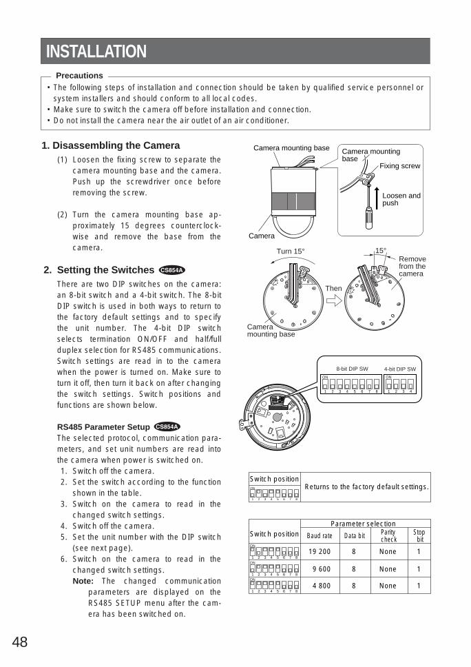
48
• The following steps of installation and connection should be taken by qualified service personnel orsystem installers and should conform to all local codes.
• Make sure to switch the camera off before installation and connection.• Do not install the camera near the air outlet of an air conditioner.
Camera mounting base
Camera
Camera mounting base
Fixing screw
Loosen and push
1 2 3 4
ON
1 2 3 4
ON
5 6 7 8
8-bit DIP SW 4-bit DIP SW
INSTALLATION
1. Disassembling the Camera(1) Loosen the fixing screw to separate the
camera mounting base and the camera.Push up the screwdriver once beforeremoving the screw.
(2) Turn the camera mounting base ap-proximately 15 degrees counterclock-wise and remove the base from thecamera.
2. Setting the Switches There are two DIP switches on the camera:an 8-bit switch and a 4-bit switch. The 8-bitDIP switch is used in both ways to return tothe factory default settings and to specifythe unit number. The 4-bit DIP switchselects termination ON/OFF and half/fullduplex selection for RS485 communications.Switch settings are read in to the camerawhen the power is turned on. Make sure toturn it off, then turn it back on after changingthe switch settings. Switch positions andfunctions are shown below.
RS485 Parameter Setup The selected protocol, communication para-meters, and set unit numbers are read intothe camera when power is switched on.1. Switch off the camera.2. Set the switch according to the function
shown in the table.3. Switch on the camera to read in the
changed switch settings.4. Switch off the camera.5. Set the unit number with the DIP switch
(see next page).6. Switch on the camera to read in the
changed switch settings.Note: The changed communication
parameters are displayed on theRS485 SETUP menu after the cam-era has been switched on.
Precautions
15°Turn 15°
Then
Camera mounting base
Remove from the camera
1 2 3 4
ON
5 6 7 8
Switch positionReturns to the factory default settings.
1 2 3 4
ON
5 6 7 8
1 2 3 4
ON
5 6 7 8
1 2 3 4
ON
5 6 7 8
Switch positionParameter selection
Baud rate
1
1
1
None
None
None
8
8
8
19 200
9 600
4 800
Data bit Parity check
Stop bit

49
Unit NumberSwitch 1, an 8-bit DIP switch, specifies unit number or returns tothe factory default settings for Panasonic’s protocol.When the unit number 1-96* is selected, it should be set on theRS485 SETUP menu (see page 46). 1 2 3 4
ON
5 6 7 8
8-bit DIP SW
For Panasonic’s Protocol
1 2 3 4
ON
5 6 7 8
Switch positionUnit
number
1 2 3 4
ON
5 6 7 8
1 2 3 4
ON
5 6 7 8
1 2 3 4
ON
5 6 7 8
1 2 3 4
ON
5 6 7 8
1 2 3 4
ON
5 6 7 8
1 2 3 4
ON
5 6 7 8
1 2 3 4
ON
5 6 7 8
1 2 3 4
ON
5 6 7 8
1 2 3 4
ON
5 6 7 8
1 2 3 4
ON
5 6 7 8
1 2 3 4
ON
5 6 7 8
1 2 3 4
ON
5 6 7 8
1 2 3 4
ON
5 6 7 8
1 2 3 4
ON
5 6 7 8
1 2 3 4
ON
5 6 7 8
1 2 3 4
ON
5 6 7 8
1 2 3 4
ON
5 6 7 8
1 2 3 4
ON
5 6 7 8
1 2 3 4
ON
5 6 7 8
1 2 3 4
ON
5 6 7 8
1 2 3 4
ON
5 6 7 8
1 2 3 4
ON
5 6 7 8
1 2 3 4
ON
5 6 7 8
1 2 3 4
ON
5 6 7 8
1 2 3 4
ON
5 6 7 8
1 2 3 4
ON
5 6 7 8
1 2 3 4
ON
5 6 7 8
1 2 3 4
ON
5 6 7 8
1 2 3 4
ON
5 6 7 8
1 2 3 4
ON
5 6 7 8
1 2 3 4
ON
5 6 7 8
Switch positionUnit
number Switch positionUnit
number
1-96*
1
2
3
4
5
6
7
8
9
10
11
12
13
14
15
16
17
18
19
20
21
22
23
24
25
26
27
28
29
30
31
32
33
34
35
36
37
38
39
40
41
42
43
44
45
46
47
48
49
50
51
52
53
54
55
56
57
58
59
60
61
62
63
64
65
66
67
68
1 2 3 4
ON
5 6 7 8
1 2 3 4
ON
5 6 7 8
1 2 3 4
ON
5 6 7 8
1 2 3 4
ON
5 6 7 8
1 2 3 4
ON
5 6 7 8
1 2 3 4
ON
5 6 7 8
1 2 3 4
ON
5 6 7 8
1 2 3 4
ON
5 6 7 8
1 2 3 4
ON
5 6 7 8
1 2 3 4
ON
5 6 7 8
1 2 3 4
ON
5 6 7 8
1 2 3 4
ON
5 6 7 8
1 2 3 4
ON
5 6 7 8
1 2 3 4
ON
5 6 7 8
1 2 3 4
ON
5 6 7 8
1 2 3 4
ON
5 6 7 8
1 2 3 4
ON
5 6 7 8
1 2 3 4
ON
5 6 7 8
1 2 3 4
ON
5 6 7 8
1 2 3 4
ON
5 6 7 8
1 2 3 4
ON
5 6 7 8
1 2 3 4
ON
5 6 7 8
1 2 3 4
ON
5 6 7 8
1 2 3 4
ON
5 6 7 8
1 2 3 4
ON
5 6 7 8
1 2 3 4
ON
5 6 7 8
1 2 3 4
ON
5 6 7 8
1 2 3 4
ON
5 6 7 8
1 2 3 4
ON
5 6 7 8
1 2 3 4
ON
5 6 7 8
1 2 3 4
ON
5 6 7 8
1 2 3 4
ON
5 6 7 8
1 2 3 4
ON
5 6 7 8
1 2 3 4
ON
5 6 7 8
1 2 3 4
ON
5 6 7 8
1 2 3 4
ON
5 6 7 8
1 2 3 4
ON
5 6 7 8
(to be continued)

50
1 2 3 4
ON
5 6 7 8
Switch positionUnit
number
1 2 3 4
ON
5 6 7 8
1 2 3 4
ON
5 6 7 8
1 2 3 4
ON
5 6 7 8
1 2 3 4
ON
5 6 7 8
1 2 3 4
ON
5 6 7 8
1 2 3 4
ON
5 6 7 8
1 2 3 4
ON
5 6 7 8
1 2 3 4
ON
5 6 7 8
1 2 3 4
ON
5 6 7 8
1 2 3 4
ON
5 6 7 8
1 2 3 4
ON
5 6 7 8
1 2 3 4
ON
5 6 7 8
1 2 3 4
ON
5 6 7 8
1 2 3 4
ON
5 6 7 8
1 2 3 4
ON
5 6 7 8
1 2 3 4
ON
5 6 7 8
1 2 3 4
ON
5 6 7 8
Switch positionUnit
number Switch positionUnit
number
69
70
71
72
73
74
75
76
77
78
79
80
81
82
83
84
85
86
87
88
89
90
91
92
93
94
95
1 2 3 4
ON
5 6 7 8
1 2 3 4
ON
5 6 7 8
1 2 3 4
ON
5 6 7 8
1 2 3 4
ON
5 6 7 8
1 2 3 4
ON
5 6 7 8
1 2 3 4
ON
5 6 7 8
1 2 3 4
ON
5 6 7 8
1 2 3 4
ON
5 6 7 8
1 2 3 4
ON
5 6 7 8

51
BP 2
Switchposition
BP 1 Function
Function
Switchposition
RS485 SettingThe 4-bit DIP switch in used forRS485 termination.
ON
Marking
1. Mark the mounting holes on the ceiling,using the removed camera mounting baseas a template.
2. Fix the camera mounting base to the ceilingwith four screws (not provided, M4).
Note: Remove sharp edges to protect thecables.
3. Assemble the CameraReverse the disassembly procedure. Takecare not to cut any cables.
OFF
Termination ON
Termination OFF *
b. Top Cable ExitPrepare a hole in the ceiling board to runthe cables.
1 2 3 4
ON
4-bit DIP SW
BP 3 BP 4
ON ON ON
OFF OFF OFF
Half duplex (2 line)
Full duplex (4 line) *
Notes:• Defaults are marked with *.• BP stands for Bit Position.• Daisy chain connection is not available for
Full Duplex. (Only for Panasonic’s systemcontrollers)
Be sure to select a ceiling board strongenough to support 4 times the total weight ofthe camera.
Precaution
a. Sideway Cable ExitPrepare a cutout in the diecast case anddecoration cover as shown in the followingfigures.
Cutout in Diecast Case
Cutout in Decoration Cover

52
5. Tighten the fixing screw M3 (provided).Notes :(1) Tighten the camera fixing screw with a
screwdriver.(2) Follow the instructions given here to
ensure that the camera and cameramounting base are installed safely.
(3) When removing the camera from thecamera mounting base, loosen andpress up the camera fixing screw (M3)by using a screwdriver.
6. Fix the decoration cover to the cameramounting base.
a. Sideway Cable ExitPass the cables through the cutout made inthe diecast case and decoration cover.
b. Top Cable ExitPush the decoration cover against the cam-era mounting base.
15°
Be sure to match the wire with the fall prevention wire fixing angle as shown below.
Fall preventionwire fixing angle
Ring of thefall prevention wire
Cautions:• Use the supplied dust protection sheet if the
camera mounting base is liable to beexposed to a dusty atmosphere. Removethe cover from the dust protection sheet,then stick the sheet on the camera mountingbase.
• Remove the sheet before mounting the cam-era on the base.
• While the camera is separated from thebase, keep the camera in the supplied poly-ethylene sack.
4. Mount the camera on the camera mountingbase and rotate the camera clockwise.
3. Hook the Fall prevention wire on the cameramounting base.

53
#24(0.22mm2)
Copper wire size(AWG)
Lengthof cable(approx.)
(m)
(ft)
#22(0.33mm2)
#20(0.52mm2)
#18(0.83mm2)
20 30 45 75
65 100 160 260
Accessory Connector Information
Pin no. Power source
1
2
3
4
24 V AC LIVE
24 V AC NEUTRAL
Ground
Not use
Contact
Up Wire
Prepare the individual conductors for clamping.Use MOLEX band tool part number 57027-5000(for UL-Style Cable UL1015) or 57026-5000 (forUL-Style UL1007) for clamping the contacts.After clamping the contacts, push them into theproper holes in the accessory connector of thiscamera until they snap in place.
• Shrinking the cable-entry seal is a one-time procedure. Do not shrink the cable-entry seal until it has been ascertainedthat the unit is functioning.CONNECT THIS TO 24 V AC CLASS 2POWER SUPPLY ONLY.
• To prevent fire or electric shock hazard,use a UL listed cable (VW-1, style 1007)should be used for the cable for the 24 VAC Input Terminals.
Contact InsertUp A
Approx.0.1 inch
Insert the wire until A positionand clamp the contacts.
Wire
UpWire
Contact
UpContact
WireApprox.3 mm (0.1 inch)
Insert the wire until A positionand clamp the contacts.
1
3
2
4
• 24 V AC Power Supply Connection
Recommended wire gauge sizes for 24 V AC line.
CAUTIONS
Note: When powered up, the unit performs a self-check (including one panning, tilting, zooming andfocusing operation).
The coaxial cable length (RG-59/U, BELDEN 9259) for the connection is up to900 meters (3,000 ft.)
To VIDEO IN(CAMERA IN)
Video output
24 V AC
BNC plug
Coaxial cable
RS485 cableData port
CONNECTIONS
BNC plugAlarm in
Alarm out
To sensors
To indicators
• The following connections should be made by qualified service personnel or system installers inaccordance with NEC 725-51.
• Make sure to switch the camera off before installation or connection.
Precautions
24 V AC cable
How to Assemble the Cable with theAccessory ConnectorStrip back the cable jacket approx. 3 mm (0.1inch) and separate the individual conductors.

54
Gray
White
Pink
Yellow green or light blue
Black
Brown
Red
Orange
Yellow
Light blue or green
Blue
Purple
Wire color
Wire color
• RS485 Connection
Note:Use the cable that is described below for RS485 site communication.
• Shielded, twisted pair cable• Low impedance• Wire gauge size is thicker than AWG #22 (0.33 mm2).
• ALARM IN Connections An 8-pin and a 4-pin harness are supplied with the camera as standard accessories. Connect exter-nal sensors to this connector. Input specifications are low-active, non-voltage contact (ON whenactive) or open collector (Low when active). The table below shows wire colors versus pin functions.
GNDBrown
Red
Data transmission
Data reception
Orange
Yellow
Green
T (B)
T (A)
R (B)
R (A)
Note: Use a relay if the voltage or current of the connected device exceeds the ratings.
• ALARM OUT Connections Connect an external device, for example, a buzzer or lamp, to this connector. Output specificationsare low-active, open-collector and a drive capacity of 16 V DC 100 mA maximum. The table belowshows wire colors versus pin functions.
Function
OUT 1
GND
OUT 2
GND
Alarm OUT (4-pin)
Function
IN 1
GND
IN 2
GND
IN 3
GND
IN 4
GND
Alarm IN (8-pin)

55
1 2 3
4 5 6
7 8 9
MON CAM
ESC SET
0
ACKRESET
BACKSEQ
FORWARDSEQ ALT
DEC–1CAM
INC+1CAM STOP1 2
AUX
CLOSE OPENIRIS
PRESET
FOCUSNEAR
ZOOMTELE
FARWIDE
System Controller WV-CU 550550B
LEFT RIGHT
UP
DOWN
ALARM BUSY
F3 F4F2F1
AF
1 2 3
4 5 6
7 8 9
MON CAM
ESC SET
0
ACKRESET
BACKSEQ
FORWARDSEQ ALT
DEC–1CAM
INC+1CAM STOP1 2
AUX
CLOSE OPENIRIS
PRESET
FOCUSNEAR
ZOOMTELE
FARWIDE
System Controller WV-CU 550550B
LEFT RIGHT
UP
DOWN
ALARM BUSY
F3 F4F2F1
AF
1 2 3
4 5 6
7 8 9
MON CAM
ESC SET
0
ACKRESET
BACKSEQ
FORWARDSEQ ALT
DEC–1CAM
INC+1CAM STOP1 2
AUX
CLOSE OPENIRIS
PRESET
FOCUSNEAR
ZOOMTELE
FARWIDE
System Controller WV-CU 550550B
LEFT RIGHT
UP
DOWN
ALARM BUSY
F3 F4F2F1
AF
1 2 3
4 5 6
7 8 9
MON CAM
ESC SET
0
ACKRESET
BACKSEQ
FORWARDSEQ ALT
DEC–1CAM
INC+1CAM STOP1 2
AUX
CLOSE OPENIRIS
PRESET
FOCUSNEAR
ZOOMTELE
FARWIDE
System Controller WV-CU 550550B
LEFT RIGHT
UP
DOWN
ALARM BUSY
F3 F4F2F1
AF
Max. 64 cameras
VCRs (up to 16)
Monitors (up to 16)
Printer
System controller
Combination camera
MatrixswitcherPersonal computer
RS-232C port
System statusmonitor
Alarm inputs
Note: When any peripheral is turned off and turned on again, the camera is also turned off and turnedback on.
SYSTEM CONNECTIONS

56
approx. 6 s (FAR/NEAR) in manual mode
WV-CS854A
Minimum illumination
Bright object
SmearWhen the camera is aimed at a bright light, suchas a spotlight, or a surface that reflects brightlight, smear or blooming may appear. Therefore,the camera should be operated carefully in thevicinity of extremely bright objects to avoidsmear or blooming.
General
Lens
WV-CS854A WV-CS554Power requiredPower consumptionPick-up deviceScanning areaScanning systemScanning frequencySynchronizationVideo output
Resolution (at center)
Signal-to-noise ratioDynamic range
Ambient operating tem-peratureDimensionsWeight
24 V AC, 60 Hz
WV-CS554Zoom ratioFocal length
Maximum aperture ratio
Iris rangeAngular field of viewZoom speedFocus speed
22 times + digital zoom x 103.79 mm - 83.4 mm
1 : 1.6 (WIDE) - 1 : 3.0 (TELE)
F1.6 - F22, closehorizontal: 2.6˚ - 51.7˚, vertical: 2.0˚ - 39.9˚approx. 4.5 s (TELE/WIDE) in manual mode approx. 7.5 s
22 times + digital zoom x 2
14 W755 (H) x 485 (V) pixels, interline transfer CCD3.59 (H) x 2.70 (V) mm (equivalent to scanning area of 1/4” pick-up tube)2 : 1 interlacehorizontal: 15.734 kHz, vertical: 59.94 Hzinternal, line-locked or multiplexed vertical drive (VD2) selectable1.0 V[p-p] composite / 75 Ωhorizontal: more than 480 lines
(C/L mode), more than 570lines (B/W mode)
vertical: more than 350 linesmore than 50 dB (AGC Off, weight on)46 dB Super-D2 On1.0 lx (0.1 foot-candle) at C/L mode,0.06 lx (0.006 foot-candle) at B/W modewith 2 times sensitivity up (AGC HIGH)
–10˚C - +50˚C (14˚F - 122˚F)
120 mm (D) x 191 mm (H) [4-3/4” (D) x 7-1/2” (H)]2 kg (4.4 lbs)
2.0 lx (0.2 foot-candle)
horizontal: more than 480 lines
vertical: more than 350 lines
SPECIFICATIONS
PREVENTION OF BLOOMING AND SMEAR

57
Image HoldProportional pan/tilt
Tilting speed
Alarm input/output
———
manual: approx.1˚/s - 24˚/s, 8-steps/16-stepssequence mode: maximum approx.300˚/s
Weight and dimensions indicated are approximate.Specifications are subject to change without notice.
Pan / Tilt
WV-CS854A WV-CS554Panning rangePanning angle settingPanning mode
Panning speed
Tilting rangeTilting mode
360˚ endlesspossible (in auto pan mode)manual, sequence, sort, auto panmanual: approx. 0.1˚/s - 120˚/s,8-steps/64-stepssequence mode: maximum approx.300˚/s
manual: approx.1˚/s - 24˚/s, 8-steps/16-stepssequence mode: maximum approx.300˚/s
0˚ - 180˚ 0˚ - 90˚manual, sequence, sort
manual: approx. 0.1˚/s - 120˚/s,8-steps/64-stepssequence mode: maximum approx.300˚/s
Functions
WV-CS854A WV-CS554Control interfacePreset control
Titles (ID)
Auto focusElectronic shutter
Electronic sensitivity upSuper-D2B/W modeAuto modeAuto pan keyDigital flipPrivacy zoneMotion detector
DNR
multiplexed control data or RS-48564 preset positions 8 preset positionspreset ID, camera ID, area title: up to16 charactersmanual / auto1/60 (Off), 1/100, 1/250, 1/500, 1/1 000, 1/2 000, 1/4 000, 1/10 000 s
AGC On (LOW)/On (MID)/On/(HIGH)/Off On / Offmax. 32 times, auto / fixedOn / Offauto / On / OffOff / sequence / sort / auto pan / patrol Off / sequence / sort / auto pansequence / sort / auto pan / patrolOn / OffOn / Off, up to 8 zonesOn / Off4-input (ALARM 1 - 4), 2-output(ALARM/AUX1, B/W/AUX2)On / OffOn / OffLOW1 / LOW2 / HIGH1 / HIGH2
—
———
—
—
preset ID, camera ID: up to 16 charac-ters
multiplexed control data

58
ACCESSORIES
OPTIONAL ACCESSORIES
Decoration cover .................................................. 1 pc.Alarm in cable ....................................................... 1 pc. Alarm out cable .................................................... 1 pc. Connector for 24 V AC .......................................... 1 pc
Dome cover (approx. 60 % transparency, smoked type) ...................... WV-CS2SDome cover (approx. 50 % transparency, smoked type) ...................... WV-CS2SHDome cover (approx. 70 % transparency, metal type) .......................... WV-CS2M

59
Selecting a PRESET position From #1 to #64#1 [1] + [CAM FUNC]#10 [1] + [0] + [CAM FUNC]#64 [6] + [4] + [CAM FUNC]
AUTO PANON [6] + [5] + [CAM FUNC]OFF [6] + [6] + [CAM FUNC]Speed Up [6] + [7] + [CAM FUNC]Speed Down [6] + [8] + [CAM FUNC]Setting Start Point [6] + [9] + [CAM FUNC]Setting End Point [7] + [0] + [CAM FUNC]Setting PAN Reverse [7] + [4] + [CAM FUNC]
AUTO MODEMODE Off [7] + [1] + [CAM FUNC]SEQ On [7] + [2] + [CAM FUNC]SORT On [7] + [3] + [CAM FUNC]
ENDLESS PANOn [7] + [6] + [CAM FUNC]Off [7] + [7] + [CAM FUNC]
DIGITAL FLIP On [7] + [8] + [CAM FUNC]Off [7] + [9] + [CAM FUNC]
PROP. PAN/TILTOn [8] + [0] + [CAM FUNC]Off [8] + [1] + [CAM FUNC]
SUPER-D2On [8] + [4] + [CAM FUNC]Off [8] + [5] + [CAM FUNC]
AUTO FOCUSSTOP AF On* [8] + [6] + [CAM FUNC]STOP AF Off* [8] + [7] + [CAM FUNC]AF On (Activate) [8] + [8] + [CAM FUNC]
HOME POSITIONMove to HOME [8] + [9] + [CAM FUNC]
B/W or C/L B/W On* [9] + [0] + [CAM FUNC]B/W Off* [9] + [1] + [CAM FUNC]B/W AUTO* [9] + [2] + [CAM FUNC]
CAMERA IDOn [9] + [3] + [CAM FUNC]Off [9] + [4] + [CAM FUNC]
AREA TITLENESW On [9] + [5] + [CAM FUNC]USER On [9] + [6] + [CAM FUNC]TITLE Off [9] + [7] + [CAM FUNC]
EL-ZOOMOn [9] + [8] + [CAM FUNC]Off [9] + [9] + [CAM FUNC]
RESTARTBegin [1] + [0] + [0] + [CAM FUNC]
Memorize PRESET From #1 to #64**Position #1 [1] + [0] + [1] + [CAM FUNC]Position #10 [1] + [1] + [0] + [CAM FUNC]Position #64 [1] + [6] + [4] + [CAM FUNC]
PATROLPLAY [1] + [6] + [5] + [CAM FUNC]STOP [1] + [6] + [6] + [CAM FUNC]LEARN(Start) [1] + [6] + [7] + [CAM FUNC]
IRISOpen [1] + [6] + [9] + [CAM FUNC]Close [1] + [7] + [0] + [CAM FUNC]
EL-SHUTTEROn [1] + [7] + [1] + [CAM FUNC]Off [1] + [7] + [2] + [CAM FUNC]Speed Up [1] + [7] + [3] + [CAM FUNC]Speed Down [1] + [7] + [4] + [CAM FUNC]
AGCOn [1] + [7] + [5] + [CAM FUNC]Off [1] + [7] + [6] + [CAM FUNC]
SENS UPOn [1] + [7] + [7] + [CAM FUNC]Off [1] + [7] + [8] + [CAM FUNC]Up [1] + [7] + [9] + [CAM FUNC]Down [1] + [8] + [0] + [CAM FUNC]
SENS UP AUTOOn [1] + [8] + [1] + [CAM FUNC]Off [1] + [8] + [2] + [CAM FUNC]Up [1] + [8] + [3] + [CAM FUNC]Down [1] + [8] + [4] + [CAM FUNC]
LL SYNC phaseINC [1] + [8] + [5] + [CAM FUNC]DEC [1] + [8] + [6] + [CAM FUNC]
PAN180° turn [1] + [8] + [7] + [CAM FUNC]
CLEANINGOn [1] + [8] + [8] + [CAM FUNC]Off [1] + [8] + [9] + [CAM FUNC]
BW SW AUTO30 sec. [1] + [9] + [0] + [CAM FUNC]60 sec. [1] + [9] + [1] + [CAM FUNC]300 sec. [1] + [9] + [2] + [CAM FUNC]600 sec. [1] + [9] + [3] + [CAM FUNC]
Function
APPENDIXShortcutsShortcut operations are available to controllers having the CAM FUNCTION key. Pressing numeric key(s)for one digit up to three digits then CAM FUNCTION key implements the respective functions as follows.The CAM FUNCTION key is abbreviated to [CAM FUNC] here.
Key Function Key
Notes: • Shortcut operations marked with * will change parameter settings only. Actual operation takes place
when the conditions for the changed settings are met.• As entering shortcuts marked with **, “NO REGS. ; FLIP ON” may appear on the monitor. Re-enter the
shortcut.• Shortcuts may be ignored while PAN/TILT, ZOOM or FOCUS is in operation.• PATROL LEARN saves only [1] through [6]+[4], [1]+[6]+[9] and [1]+[7]+[0] in the memory.• PATROL PLAY stops when a shortcut other than [1]+[6]+[9] or [1]+[7]+[0] is entered.

N0701-1071 V8QA5748BN Printed in JapanImprimé au Japon
2001 © Matsushita Communication Industrial Co., Ltd.
Panasonic Canada Inc.5770 Ambler Drive, Mississauga,Ontario, L4W 2T3 Canada (905)624-5010
Panasonic Sales CompanyDivision of Matsushita Electric of Puerto Rico Inc.Ave. 65 de Infanteria. Km. 9.5San Gabriel Industrial Park, Carolina,Puerto Rico 00985 (809)750-4300
Panasonic Security and Digital Imaging CompanyA Division of Matsushita Electric Corporation of AmericaExecutive Office: One Panasonic Way 3E-7, Secaucus, New Jersey 07094Regional Offices:Northeast: One Panasonic Way, Secaucus, NJ 07094 (201) 348-7303Southern: 1225 Northbrook Parkway, Suite 1-160, Suwanee,
GA 30024 (770) 338-6838Midwest: 1707 North Randall Road, Elgin, IL 60123 (847) 468-5211Western: 6550 Katella Ave., Cypress, CA 90630 (714) 373-7840