Embed Size (px)
Citation preview
WSA XXX Water Industry Standard for
polymeric spray lining materials used for
the renovation of drinking water pipes
Issue: Draft for Public Comment
2
ACKNOWLEDGEMENTS
The Australian Government, through the Cooperative Research Centre, provided funding for
the Smart Linings for Pipe and Infrastructure Project that produced this Water Industry
Standard. The CRC Program supports industry-led collaborations between industry,
researchers and the community.
The WSAA Board would like to express its appreciation to the project participants, all of whom
contributed expertise, labour, funding, products or trial sites to assist in the delivery of this
Water Industry Standard. In particular the following organisations deserve a special mention
for their productive work and commitment to the development of this Water Industry Standard:
Abergeldie Insituform The Australasian Society for Trenchless Technology
Alan Whittle Interflow The University of Sydney
Bisley Melbourne Water The University of Technology Sydney
Calucem Metrocorp The Water Research Foundation
Central Highlands Water Monash University UKWIR
City West Water Nuflow Unity Water
Coliban Water Parchem Urban Utilities
Downer Group SA Water Ventia
GeoTree Solutions Sanexen Water Corporation
Hunter Water South East Water Wilsons Pipe Solutions
Icon Water Sydney Water Yarra Valley Water
DISCLAIMER
WSAA Codes are published by Water Services Association of Australia Limited on the
understanding that:
Water Services Association of Australia Limited and individual contributors are not
responsible for the results of any action taken on the basis of information in the Water
Supply Code of Australia, nor any errors or omissions.
Water Services Association of Australia Limited and individual contributors disclaim all and
any liability to any person in respect of anything, and the consequences of anything, done or
omitted to be done by a person in reliance upon the whole or any part of the Water Supply
Code of Australia.
PUBLICATION DETAILS
Published by:
Water Services Association of Australia Limited
3
Level 8, Suite 802, 401 Docklands Drive, Docklands Victoria 3009 Australia
ISBN [to be included in published version]
COPYRIGHT
This document is copyrighted. Apart from any use as permitted under the Copyright Act
1968, and except where provided for below, no part of this document may be reproduced or
transmitted in any form or by any means, electronic or mechanical, for any purpose, without
the express written permission of Water Services Association of Australia Limited.
Water Services Association of Australia will permit up to 10 percent of the technical content
pages of this Code to be copied for use exclusively in house by purchasers of this Code
without payment of a royalty or advice to Water Services Association of Australia Limited.
© Copyright 2021 by Water Services Association of Australia Limited. All rights reserved.
4
PREFACE
This Standard was prepared by the Water Services Association of Australia (WSAA). It was
published on the [to be included in published version].
The objective of this Standard is to provide performance requirements for in-situ polymeric
spray linings intended for the renovation of pipeline systems used for the supply of drinking
water.
NOTE: Products complying with this Standard may also be suitable for the renovation of
water pipes used for other applications such as recycled water, fire services and irrigation.
Selection, design and installation and commissioning requirements are covered by WSAA
Manual for selection and application of cured-in-place pipe (CIPP) and spray liners for use in
water pipe.
5
CONTENTS
Page
PREFACE
CONTENTS
FOREWORD
1 SCOPE AND GENERAL
1.1 SCOPE
1.2 CONFORMITY REQUIREMENTS
1.3 LIMITATIONS
1.4 NORMATIVE REFERENCES
1.5 TERMS AND DEFINITIONS
1.6 NOTATION
2 MATERIAL REQUIREMENTS ‘“M” STAGE
2.1 MATERIAL SPECIFICATION - RESIN SYSTEM
2.2 STORAGE AND TRANSPORT
2.3 MARKING
2.4 FITTINGS AT THE “M” STAGE
3 MATERIAL REQUIREMENTS “I” STAGE
3.1 MATERIALS SPECIFICATION – CURED RESIN
3.2 EFFECT ON DRINKING WATER
3.3 SURFACE IRREGULARITIES
3.4 SPANNING OF EXISTING HOLES AND GAPS
3.5 ACCEPTABLE BEND RADIUS
3.6 OTHER MATERIALS
4 OTHER MATERIALS
4.1 ELASTOMERIC SEALS
4.2 ADHESIVES AND SEALANTS
4.3 EFFECT OF OTHER MATERIALS ON LINER CLASS
5 MECHANICAL PROPERTIES
5.1 GENERAL
5.2 TESTING AND CONDITIONING TEMPERATURES
5.3 TEST REQUIREMENTS
6 SAMPLING
7 ADDITIONAL CHARACTERISTICS
7.1 RECONNECTION TO THE EXISTING NETWORK
7.2 RECONNECTION OF EXISTING SERVICES
6
7.3 CONNECTION OF NEW SERVICES
7.4 CONNECTION OF NEW OFFTAKES
7.5 REPAIR OF RENOVATED PIPELINE
7.6 CHEMICAL RESISTANCE
7.7 OTHER
8 PRODUCT DOCUMENTATION
8.1 GENERAL
8.2 PRODUCT DATA
8.3 INSTALLATION INSTRUCITONS
APPENDIX A
MEANS OF DEMONSTRATING CONFORMITY WITH THIS STANDARD
APPENDIX B
STRUCTURAL CLASSIFICATION OF LINERS
BIBLIOGRAPHY
7
FOREWORD
This Standard addresses the performance requirements of polymeric spray lining materials
and finished products used in the renovation of drinking water pipelines. It is intended to
provide manufacturers and specifiers with a means of demonstrating fitness for purpose.
This Standard differs from those applicable to conventionally installed piping systems in that
it is required to verify certain characteristics of the components as manufactured as well as
in the installed condition. In accordance with ISO terminology these have been identified as
the “M” stage for the collective materials used to fabricate the liner and the “I” stage for the
liner as installed.
ISO terminology has also been adopted for describing the structural classification with Class
A being fully structural, Classes B and C being semi-structural and Class D providing an
internal barrier layer (refer to appendix B for class requirements). Spray linings are usually
Class B, C or D. Class D spray linings typically have a wall thickness 1-1.5mm, whilst Class
B or C spray linings have a typical wall thickness of 3-6mm (depending on pipe diameter).
The service life of products conforming to this Standard will be dependent upon the condition
of the host pipe, the quality of the liner material and its application, and the service
conditions. The material and process selection should therefore be in accordance with the
requirements of the asset owner with respect to extending the service life of the host
pipeline.
The type of polymer is not specified in the Standard but typically two-part epoxy,
polyurethane or polyurea have been used for relining water pipes. All materials used are
required to meet the performance requirements of this Standard including effect on drinking
water.
As part of its product appraisal process, WSAA may request details of previous successful
installations or require contractors to undertake trial installations. Such trial details may
include:
• The host pipe diameter and length, material and service conditions;
• The lining material
• Specified thickness and measurements of applied liner thickness;
• The water off time (time from water off to supply restoration);
• Disinfection regime;
• Contractor details and date of installation;
• Where relevant, details of any subsequent rectification work applied to the renovation;
• Internal CCTV examination of the lined pipe including joints, service connections,
hydrants and liner ends. CCTV shall include a view into service connections, hydrants
and other fittings; and
• Pressure test, or leak test, results.

8
1. SCOPE AND GENERAL
1.1. SCOPE
This Standard specifies the performance requirements and test methods for solvent
free, in-situ polymeric spray linings for use in the renovation of drinking water
pipelines. It is applicable to the spray lining of host pipes including, but not limited to,
asbestos cement, cement mortar lined metallic, unlined metallic, and reinforced
concrete pipes.
The Standard is applicable to semi-structural (Class B and Class C) and non-
structural (Class D) spray linings as defined in Appendix B.
It is applicable to the spray lining intended to be installed in accordance with the
WSAA Manual for selection and application of cured-in-place (CIPP) and spray
liners for use in water pipe.
NOTES:
(i) Spray lining resin systems for the renovation of water pipes made of
materials not listed in this standard may require additional testing. For
example, assessment of the liner adhesion to alternate substrates and
chemical compatibility between the liner and pipe material.
(ii) No minimum pressure rating is specified for spray-lining applications as the
appropriate pressure requirements will be stipulated by the Water Agency on
a case-by-case basis.
(iii) This Standard does not set requirements for abrasion resistance or impact
resistance. This Water Industry Standard only considers application in water
pipes, where no significant impacts due to abrasion or impact occurs.
1.2. CONFORMITY REQUIREMENTS
Methods for demonstrating conformity with this Standard shall be in accordance with
Appendix A.
Product certification, when required, shall be undertaken in accordance with WSA
TN-08.
Note: The word ‘shall’ is used in this Standard to designate a mandatory
requirement.
1.3. LIMITATIONS
This Standard applies to spray lining products that rely on a degree of structural
integrity of the host pipe to both withstand external loads and resist internal
pressure.
1.4 NORMATIVE REFERENCES
The following are the normative documents referenced in this Standard:
AS
681.1 Elastomeric seals- Material requirements for pipe joint seals used in water and
9
drainage applications Part 1: Vulcanized rubber.
1199.1 Sampling procedures for inspection by attributes — Part 1: Sampling
schemes indexed by acceptance quality limit (AQL) for lot-by-lot inspection.
1281 Cement mortar lining of steel pipes and fittings
1646 Elastomeric seals for waterworks purposes.
4087 Metallic flanges for waterworks purposes.
4321 Fusion-bonded medium-density polyethylene coating and lining for
pipes and fittings
AS/NZS
1145.2 Determination of tensile properties of plastics materials - Test conditions for
moulding and extrusion plastics
2280 Ductile iron pipes and fittings
2566 Buried flexible pipelines – Part 1: Structural design
3894.9 Site testing of protective coatings, Method 9: Determination of adhesion
4020 Testing of products for use in contact with drinking water.
4158 Thermally-bonded polymeric coating on valves and fittings for water industry
purposes.
ASTM
D4541 Test 11295 method for Pull-off Strength of Coatings using Portable Adhesion
Testers.
D570 Standard Test Method for Water Absorption of Plastics.
D638 Standard Test Method for Tensile Properties of Plastics.
D696 Standard Test Method for Coefficient of Linear Thermal Expansion of Plastics
Between -30°C and 30°C with a Vitreous Silica Dilatometer.
D790 Standard Test Methods for Flexural Properties of Unreinforced and Reinforced.
Plastics and Electrical Insulating Materials.
D1599 Standard Test Method for Resistance to Short-Time Hydraulic Pressure of
Plastic Pipe, Tubing, and Fittings.
D2290 Test Method for Apparent Hoop Tensile Strength of Plastic or Reinforced
Plastic Pipe.
D2369 Standard Test Method for Volatile Content of Coatings.
D2992 Standard Practice for Obtaining Hydrostatic or Pressure Design Basis for
“Fiberglass” (Glass-Fiber-Reinforced Thermosetting-Resin) Pipe and Fittings.
D3567 Standard Practice for Determining Dimensions of “Fiberglass” (Glass-Fiber-
Reinforced Thermosetting Resin) Pipe and Fittings.
D4541 Standard test method for Pull-Off Strength of Coatings using Portable
Adhesion Testers.
D7028 Standard Test Method for Glass Transition Temperature (DMA Tg) of Polymer
Matrix Composites by Dynamic Mechanical Analysis (DMA).

10
D7234 Test method for Pull-off Adhesion Strength of Coatings on Concrete using
Portable Pull-off Adhesion Testers.
E289 Standard Test Method for Linear Thermal Expansion of Rigid Solids with
Interferometry.
E831 Standard Test Method for Linear Thermal Expansion of Solid Materials by
Thermomechanical Analysis.
F1612 Standard Practice for Rehabilitation of Existing Pipelines and Conduits by the
Inversion and Curing of a Resin-Impregnated Tube.
F3182 Standard Practice for the Application of Spray-Applied Polymeric Liners Inside
Pipelines for Potable Water.
AWWA
Structural Classifications of Pressure Pipe Linings – Suggested Protocol for Product
Classification
AS ISO/IEC
17025 General requirements for the competence of testing and calibration
laboratories.
ISO
62 Plastics — Determination of water absorption.
178 Plastics — Determination of flexural properties.
527-1 Plastics — Determination of tensile properties — Part 1: General principles.
899-1 Plastics — Determination of creep behaviour — Part 1: Tensile creep.
899-2 Plastics — Determination of creep behaviour — Part 2: Flexural creep by
three-point loading.
7509 Plastics piping systems — Glass-reinforced thermosetting plastics (GRP) pipes
— Determination of time to failure under sustained internal pressure.
10928 Plastics piping systems — Glass-reinforced thermosetting plastics (GRP)
pipes and fittings — Methods for regression analysis and their use.
11295 Classification and information on the design and applications of plastics lining
systems used for renovation and replacement.
11297-4 Plastics piping systems for renovation of underground drainage and
sewerage networks under pressure — Part 4: Lining with cured-in-place pipes.
11298.4 Plastics piping systems for renovation of underground water supply
networks — Part 4: Lining with cured-in-place pipes.
11359-2 Plastics – Thermomechanical analysis (TMA) – Part 2: Determination of
coefficient of linear thermal expansion and glass transition temperature
13003 Fibre-reinforced plastics — Determination of fatigue properties under cyclic
loading conditions.
15306 Glass-reinforced thermosetting plastics (GRP) pipes — Determination of the
resistance to cyclic internal pressure.
Water UK
IGN 4-02-02 Code of Practice: In Situ Resin Lining of Water Mains
WIS 4-02-01 Operational Requirements: In Situ Resin Lining of Water Mains
WSAA
TN-08 Product conformity assessment requirements.
11
1.5. TERMS AND DEFINITIONS
For the purpose of this Standard, the following terms and definitions apply:
1.5.1. Average thickness
The mean of measurements taken to record liner thickness at the “I” stage in
accordance with section 3.5 Liner Thickness
1.5.2. Curing
process of resin polymerisation, which typically occurs at ambient
temperature.
1.5.3. Declared value
limiting value of a characteristic declared in advance by the lining system
supplier, which becomes the requirement for the purpose of assessment of
conformity.
1.5.4. Specified thickness
the specified final wall thickness of the liner resin system once installed and
cured (‘I’ stage) and includes multiple applications/passes where used
1.5.5. Dry film thickness (DFT)
the dry film thickness of a coating remaining on the surface and above the
peaks of the surface profile when the coating or system has hardened and
cured.
1.5.6. Liner thickness
the liner wall thickness following installation and curing (‘I’ stage), measured in
accordance with section 3.5 Liner Thickness
1.5.7. Lining with sprayed polymeric materials
lining with a sprayed two-part polymeric resin system material that forms a
continuous coating after resin system cure.
1.5.8. Minimum thickness
the minimum wall thickness required in the product supplier’s documentation
(recommended to be no less than 1 mm)
1.5.9. Product stages
the liner material as installed and the component materials from which it is
made can be considered as two distinct stages as follows:
1.5.9.1. “M” Stage
the stage as manufactured before any site processing or mixing of the
components.
1.5.9.2. “I” stage
the stage as installed. That is, the final configuration of the material
after site processing and installation.
1.5.10. Resin system
thermosetting resin including the curing agent(s) and any fillers or other
12
additives in specified proportions.
1.5.11. Renovation
work incorporating all or part of the original fabric of the pipeline, by means of
which its current performance is improved.
1.5.12. Renovated pipeline system
the existing pipeline system plus the installed liner used to renovate it.
1.5.13. Simulated installation
an installation of a lining system into a simulated host pipeline, using
representative equipment and processes, to provide samples for testing which
are representative of the actual installation.
1.5.14. Simulated host pipeline
a section of pipeline, which is not part of an operational network, but which
replicates the environment of the operational network.
1.5.15. Service conditions
1.5.15.1. Maximum service temperature
the maximum sustained temperature at which the spray-lining system
is intended to operate.
1.5.15.2. Nominal pressure (PN)
the alphanumeric designation for the nominal pressure class,
designated in bars, which is the maximum sustained hydraulic internal
pressure for which the pipe is designed in the absence of other loading
conditions. For example, PN12 indicates a nominal pressure of 12 Bar
or 1,200 kPa.
1.5.15.3. Maximum allowable operating pressure
the maximum pressure that can be sustained, with a design factor, by
the type or class of pipe for its estimated useful life under the
anticipated working conditions.
1.5.16. Surface area-to-volume ratio
the surface area per unit length of the liner in direct contact with the drinking
water divided by the volume of water per unit length.
1.6. NOTATION
The following symbols and abbreviations are used in the Standard:
AC Asbestos cement
CML Cement mortar lining
“I” as installed
“M” as manufactured
EP Epoxy
PEUU Polyurea
PU Polyurethane
DN Nominal size
13
PN Nominal pressure
2. MATERIAL REQUIREMENTS “M” stage
2.1. MATERIALS SPECIFICATION – RESIN SYSTEM
2.1.1. Colour
Where colour is used to provide a visual evaluation of the quality of the mixing,
the individual resin system components shall be of clearly distinguishable colours
which, when mixed correctly, provide a different distinctive colour.
Other methods of demonstrating the efficiency of the mixing of components may
be nominated by the supplier.
2.1.2. Composition
The manufacturer shall:
(i) Nominate the chemical family of the spray-lining resin. For example, epoxy,
polyurethane, or polyurea as appropriate;
(ii) Nominate the type of any fillers used;
(iii) Provide a specification for each resin system component listing relevant
properties including specified values and tolerances. The properties shall include
those listed in Table 1 and Table 2. Any other material properties relevant to the
particular spray-lining system shall also be specified;
(iv) Specify the type of in-line mixer and lining application head required and whether
a heated umbilical is necessary; and
(v) Specify the solvent to be used for cleaning.
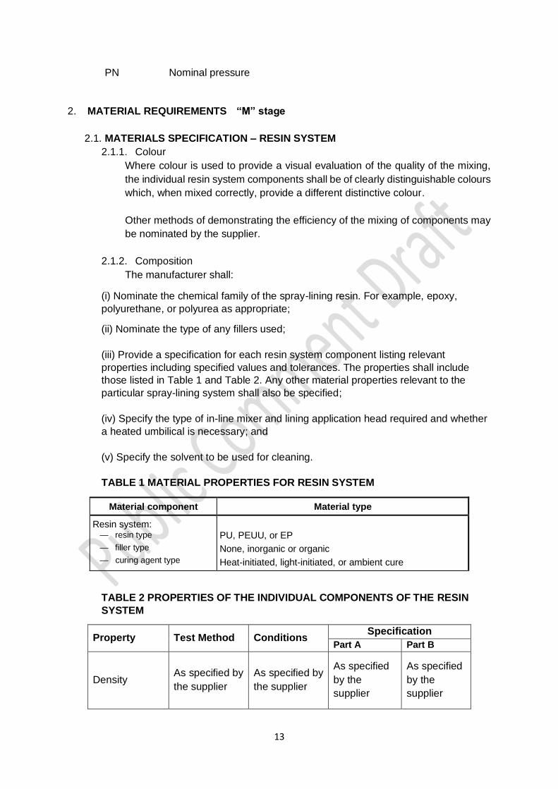
TABLE 1 MATERIAL PROPERTIES FOR RESIN SYSTEM
Material component Material type
Resin system: — resin type
— filler type
— curing agent type
PU, PEUU, or EP
None, inorganic or organic
Heat-initiated, light-initiated, or ambient cure
TABLE 2 PROPERTIES OF THE INDIVIDUAL COMPONENTS OF THE RESIN
SYSTEM
Property Test Method Conditions Specification
Part A Part B
Density As specified by
the supplier
As specified by
the supplier
As specified
by the
supplier
As specified
by the
supplier
14
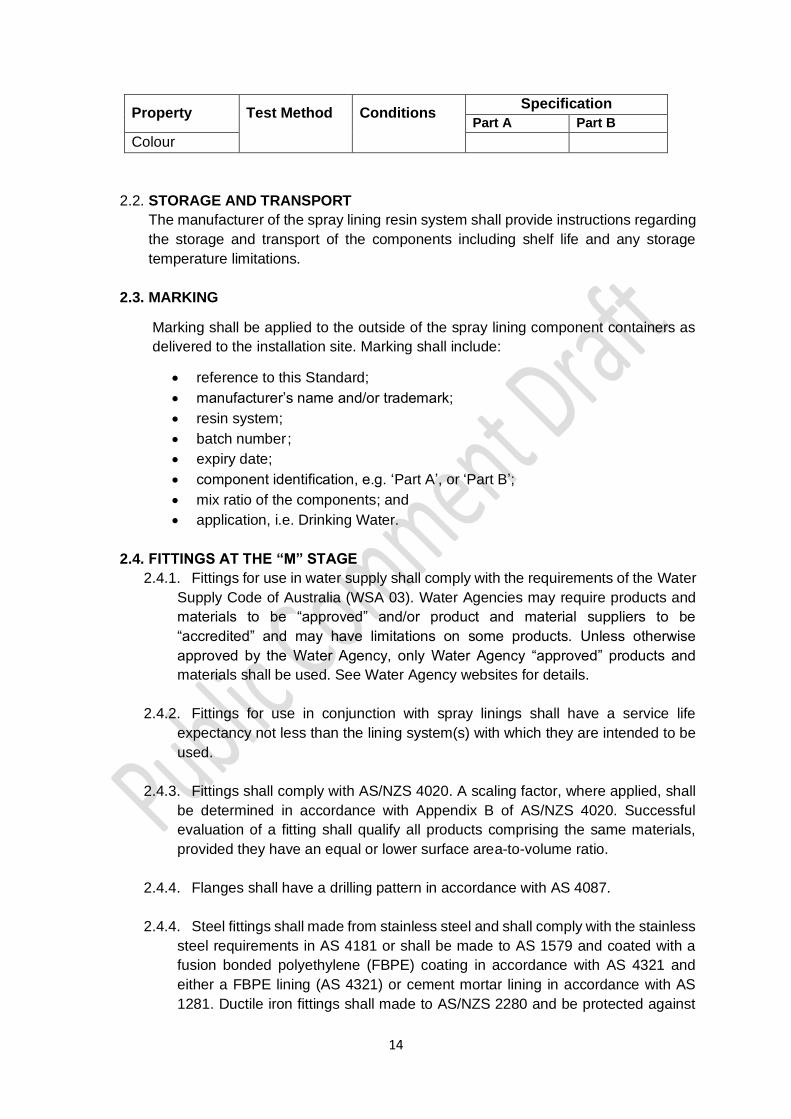
Property Test Method Conditions Specification
Part A Part B
Colour
2.2. STORAGE AND TRANSPORT
The manufacturer of the spray lining resin system shall provide instructions regarding
the storage and transport of the components including shelf life and any storage
temperature limitations.
2.3. MARKING
Marking shall be applied to the outside of the spray lining component containers as
delivered to the installation site. Marking shall include:
• reference to this Standard;
• manufacturer’s name and/or trademark;
• resin system;
• batch number ;
• expiry date;
• component identification, e.g. ‘Part A’, or ‘Part B’;
• mix ratio of the components; and
• application, i.e. Drinking Water.
2.4. FITTINGS AT THE “M” STAGE
2.4.1. Fittings for use in water supply shall comply with the requirements of the Water
Supply Code of Australia (WSA 03). Water Agencies may require products and
materials to be “approved” and/or product and material suppliers to be
“accredited” and may have limitations on some products. Unless otherwise
approved by the Water Agency, only Water Agency “approved” products and
materials shall be used. See Water Agency websites for details.
2.4.2. Fittings for use in conjunction with spray linings shall have a service life
expectancy not less than the lining system(s) with which they are intended to be
used.
2.4.3. Fittings shall comply with AS/NZS 4020. A scaling factor, where applied, shall
be determined in accordance with Appendix B of AS/NZS 4020. Successful
evaluation of a fitting shall qualify all products comprising the same materials,
provided they have an equal or lower surface area-to-volume ratio.
2.4.4. Flanges shall have a drilling pattern in accordance with AS 4087.
2.4.4. Steel fittings shall made from stainless steel and shall comply with the stainless
steel requirements in AS 4181 or shall be made to AS 1579 and coated with a
fusion bonded polyethylene (FBPE) coating in accordance with AS 4321 and
either a FBPE lining (AS 4321) or cement mortar lining in accordance with AS
1281. Ductile iron fittings shall made to AS/NZS 2280 and be protected against
15
corrosion by a thermally bonded coating applied in accordance with AS/NZS
4158..
2.4.5. Brass fittings shall be low lead and resistance to dezincification and comply
with AS 1565 and AS 2345.
2.4.6. Mild steel, ductile iron, GRP and PVC fittings shall comply with the relevant
WSAA Product Specification.
3. MATERIAL REQUIREMENTS “I” stage
This clause specifies the requirements for the completed liner installation.
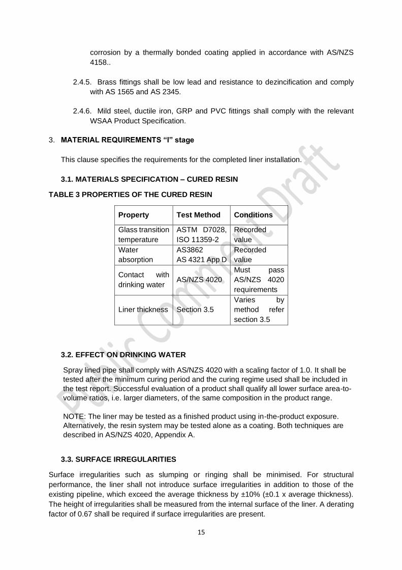
3.1. MATERIALS SPECIFICATION – CURED RESIN
TABLE 3 PROPERTIES OF THE CURED RESIN
Property Test Method Conditions
Glass transition
temperature
ASTM D7028,
ISO 11359-2
Recorded
value
Water
absorption
AS3862
AS 4321 App D
Recorded
value
Contact with
drinking water AS/NZS 4020
Must pass
AS/NZS 4020
requirements
Liner thickness Section 3.5
Varies by
method refer
section 3.5
3.2. EFFECT ON DRINKING WATER
Spray lined pipe shall comply with AS/NZS 4020 with a scaling factor of 1.0. It shall be
tested after the minimum curing period and the curing regime used shall be included in
the test report. Successful evaluation of a product shall qualify all lower surface area-to-
volume ratios, i.e. larger diameters, of the same composition in the product range.
NOTE: The liner may be tested as a finished product using in-the-product exposure.
Alternatively, the resin system may be tested alone as a coating. Both techniques are
described in AS/NZS 4020, Appendix A.
3.3. SURFACE IRREGULARITIES
Surface irregularities such as slumping or ringing shall be minimised. For structural
performance, the liner shall not introduce surface irregularities in addition to those of the
existing pipeline, which exceed the average thickness by ±10% (±0.1 x average thickness).
The height of irregularities shall be measured from the internal surface of the liner. A derating
factor of 0.67 shall be required if surface irregularities are present.
16
For uncovered joints (or joints not spanned by spray lining) leakage may occur at the joints or
through the CML. Refer section 3.4 Spanning of Existing Holes and Gaps for additional
requirements.
3.4. SPANNING OF EXISTING HOLES AND GAPS
A spray liner can be installed for a number of purposes at varying thicknesses, but when
installed as a Class B or Class C liner, it must meet the following hole and gap spanning
requirements. For a standard 3mm thick application (to achieve the minimum Class C
requirements): spray liners shall span holes during application up to a diameter of 3 mm and
gaps that are up to 3mm wide and up to 3mm deep.
Note that a liner’s ability to span holes and gaps will vary depending on the thickness of the
liner, with higher thickness spanning larger holes and gaps during installation. Where holes
and gaps are larger than 3mm a thicker layer of spray lining can be applied at the joints or
multiple passes can be used to achieve a greater liner thickness, e.g. 6 mm. Alternatively, to
ensure that joints are spanned, a filler material can be inserted into gaps at the joints prior to
liner installation. This will ensure a consistent internal pipe surface prior to spray lining. The
filler material must be compatible with the spray liner and comply with AS/NZS 4020
requirements.
CCTV shall be used to check whether all holes and gaps are spanned as part of post lining
CCTV quality control.
Products may be deemed acceptable if they do not span joints, however there is a high risk
that leakage will still occur through the joints or CML if it is not spanned by the spray liner.
Judgement on whether a liner is suitable if joints are not spanned shall be made by the asset
owner based on the primary purpose of the spray lining.
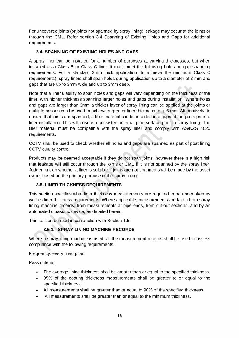
3.5. LINER THICKNESS REQUIREMENTS
This section specifies what liner thickness measurements are required to be undertaken as
well as liner thickness requirements. Where applicable, measurements are taken from spray
lining machine records, from measurements at pipe ends, from cut-out sections, and by an
automated ultrasonic device, as detailed herein.
This section be read in conjunction with Section 1.5.
3.5.1. SPRAY LINING MACHINE RECORDS
Where a spray lining machine is used, all the measurement records shall be used to assess
compliance with the following requirements.
Frequency: every lined pipe.
Pass criteria:
• The average lining thickness shall be greater than or equal to the specified thickness.
• 95% of the coating thickness measurements shall be greater to or equal to the
specified thickness.
• All measurements shall be greater than or equal to 90% of the specified thickness.
• All measurements shall be greater than or equal to the minimum thickness.

17
Report: Varies by machine. It shall include all calculated measurements and shall demonstrate
that all the pass criteria have been met. If that is not the case all non-complying measurements
shall be highlighted.
3.5.2 LINER THICKNESSES AT PIPE ENDS
At each end of the lined pipe lining thicknesses shall be measured as detailed herein. Where
the entry and/or exit is smooth, the measurements can be made directly. Where that is not
feasible, hand-held ultrasonic liner thickness measurements shall be made at a suitable
distance inside the pipe to avoid entry/exit end variations.
Frequency: At each end of every lined pipe.
Measurement location: 4 measures at clock positions: 3, 6, 9 and 12 o’clock on both pipe end
faces (8 total measurements).
Measurement equipment: micrometer, calliper or ultrasonic gauge capable of measuring to
within 0.1 mm.
Pass criteria:
• The average lining thickness shall be greater than or equal to the specified thickness.
• No more than 1 of the 8 measurements shall be less than the specified thickness.
• All measurements shall be greater than or equal to 90% of the specified thickness.
• All measurements shall be greater than or equal to the minimum thickness.
Report: It shall include all measurements and shall demonstrate that all the pass criteria have
been met. If that is not the case all non-complying measurements shall be highlighted.
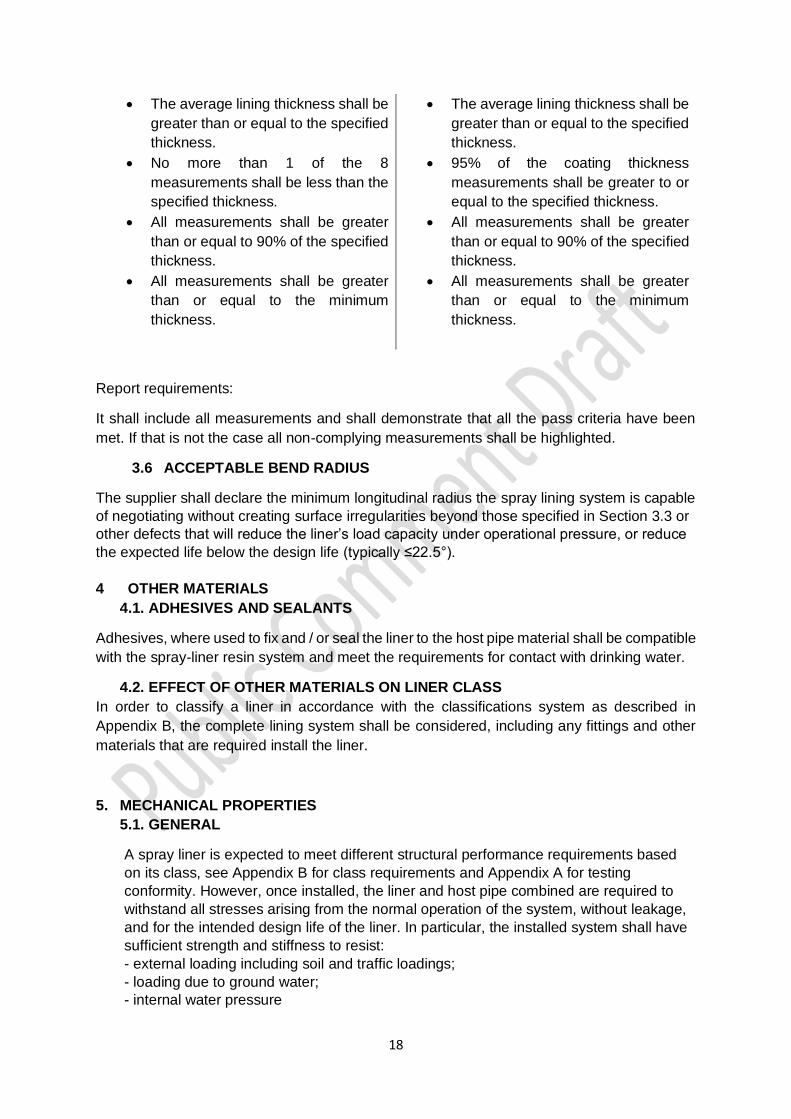
3.5.3 LINED PIPE THICKNESSES
Direct measurements shall be taken from within the lined pipe by cutting out sections or by
the use of a robot-mounted ultrasonic sensing device. Currently robot-mounted ultrasonic
sensing devices are only available for DN450 to 600mm diameter pipes.
One of the two following testing methods shall be undertaken.
Cut out method Robot-mounted ultrasonic sensor
Frequency:
• One cut out per 500m for pipes
≤DN250
• One cut out per 2km for pipes
>DN250
Frequency: Measurement of
• One shot per 500m for pipes
≤DN250
• One shot per 2km for pipes >DN250
Measurement location: 4 measures at clock
positions: 3, 6, 9 and 12 o’clock on both pipe
end faces (8 total measurements).
Measurement location: Continuously at the
crown of the pipe.
Measurement equipment: micrometer,
calliper or ultrasonic gauge capable of
measuring to within 0.1 mm.
Measurement equipment: robot-mounted
ultrasonic sensor
Pass criteria: Pass criteria:
18
• The average lining thickness shall be
greater than or equal to the specified
thickness.
• No more than 1 of the 8
measurements shall be less than the
specified thickness.
• All measurements shall be greater
than or equal to 90% of the specified
thickness.
• All measurements shall be greater
than or equal to the minimum
thickness.
• The average lining thickness shall be
greater than or equal to the specified
thickness.
• 95% of the coating thickness
measurements shall be greater to or
equal to the specified thickness.
• All measurements shall be greater
than or equal to 90% of the specified
thickness.
• All measurements shall be greater
than or equal to the minimum
thickness.
Report requirements:
It shall include all measurements and shall demonstrate that all the pass criteria have been
met. If that is not the case all non-complying measurements shall be highlighted.
3.6 ACCEPTABLE BEND RADIUS
The supplier shall declare the minimum longitudinal radius the spray lining system is capable
of negotiating without creating surface irregularities beyond those specified in Section 3.3 or
other defects that will reduce the liner’s load capacity under operational pressure, or reduce
the expected life below the design life (typically ≤22.5°).
4 OTHER MATERIALS
4.1. ADHESIVES AND SEALANTS
Adhesives, where used to fix and / or seal the liner to the host pipe material shall be compatible
with the spray-liner resin system and meet the requirements for contact with drinking water.
4.2. EFFECT OF OTHER MATERIALS ON LINER CLASS
In order to classify a liner in accordance with the classifications system as described in
Appendix B, the complete lining system shall be considered, including any fittings and other
materials that are required install the liner.
5. MECHANICAL PROPERTIES
5.1. GENERAL
A spray liner is expected to meet different structural performance requirements based
on its class, see Appendix B for class requirements and Appendix A for testing
conformity. However, once installed, the liner and host pipe combined are required to
withstand all stresses arising from the normal operation of the system, without leakage,
and for the intended design life of the liner. In particular, the installed system shall have
sufficient strength and stiffness to resist:
- external loading including soil and traffic loadings;
- loading due to ground water;
- internal water pressure
19
- vacuum pressure when dewatering the lined pipe; and
- pressure transients.
The product supplier must provide sufficient product properties evidence to enable a
design that will meet these requirements. Refer table A1 for testing requirements.
For Class B installations all the following tests are applicable. For Class C installations all
the following test are applicable, except Clause 5.6. For Class D installations only Clause
5.5 is applicable.
NOTE: For the purpose of type testing, samples may be taken either from actual
installations or from simulated installations. If anisotropic properties are noted, testing must
be conducted for both axial and hoop directions.
5.2. TENSILE PROPERTIES
5.2.1. GENERAL
Tensile properties shall be determined using the methods given in any or all of the
following standards: ASTM D638; ISO 527-1; AS 1145.2
5.2.2. NUMBER OF SAMPLES FOR TYPE TESTING
Five samples of the same size and classification shall be used conforming to 5.2.1.
Test samples shall be cut from liners having the same nominal size and layer thickness
as field installed pipes, alternatively samples can be cut from flat sheets of the same
thickness and cut using either CNC machining or waterjet cutting.
5.2.3. REQUIREMENTS
The following properties shall be declared:
• Ultimate tensile strength of liner (𝜎𝑡), in MPa
• Tensile modulus of elasticity (𝐸𝑡), in GPa
• Poisson’s ratio of the liner (𝜈𝐿), unitless
5.3. FLEXURAL PROPERTIES
5.3.1. GENERAL
Flexural properties shall be determined using the methods given in any or all of the
following standards: ASTM D790; ISO 178.
5.3.2. NUMBER OF SAMPLES FOR TYPE TESTING
Five samples of the same size and classification shall be used conforming to 5.3.1.
Test samples shall be cut from liners having the same nominal size and thickness as
field installed pipes, alternatively samples can be cut from flat sheets of the same
thickness and cut using either CNC machining or waterjet cutting.
5.3.3. REQUIREMENTS
The following properties shall be declared:
20
• Ultimate flexural strength of liner (𝜎𝑓), in MPa
• Offset yield strength at 0.2% strain, in MPa
• Strain at ultimate flexural strength, in %
• Strain at failure or 5% (if not failed), in %
• Flexural modulus of elasticity (𝐸𝑓), in GPa
If break occurs, treat the stress at break as the ultimate flexural strength (if highest
strength).
5.4. BURST PRESSURE
5.4.1. GENERAL
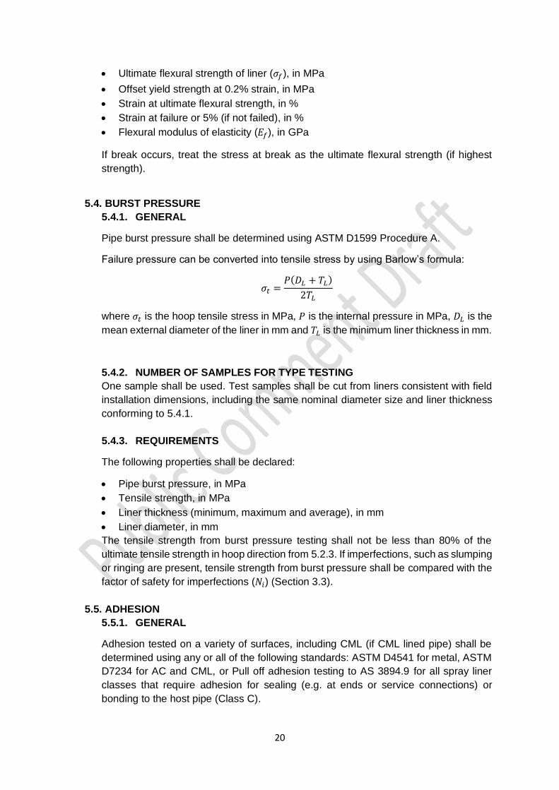
Pipe burst pressure shall be determined using ASTM D1599 Procedure A.
Failure pressure can be converted into tensile stress by using Barlow’s formula:
𝜎𝑡 =𝑃(𝐷𝐿 + 𝑇𝐿)
2𝑇𝐿
where 𝜎𝑡 is the hoop tensile stress in MPa, 𝑃 is the internal pressure in MPa, 𝐷𝐿 is the
mean external diameter of the liner in mm and 𝑇𝐿 is the minimum liner thickness in mm.
5.4.2. NUMBER OF SAMPLES FOR TYPE TESTING
One sample shall be used. Test samples shall be cut from liners consistent with field
installation dimensions, including the same nominal diameter size and liner thickness
conforming to 5.4.1.
5.4.3. REQUIREMENTS
The following properties shall be declared:
• Pipe burst pressure, in MPa
• Tensile strength, in MPa
• Liner thickness (minimum, maximum and average), in mm
• Liner diameter, in mm
The tensile strength from burst pressure testing shall not be less than 80% of the
ultimate tensile strength in hoop direction from 5.2.3. If imperfections, such as slumping
or ringing are present, tensile strength from burst pressure shall be compared with the
factor of safety for imperfections (𝑁𝑖) (Section 3.3).
5.5. ADHESION
5.5.1. GENERAL
Adhesion tested on a variety of surfaces, including CML (if CML lined pipe) shall be
determined using any or all of the following standards: ASTM D4541 for metal, ASTM
D7234 for AC and CML, or Pull off adhesion testing to AS 3894.9 for all spray liner
classes that require adhesion for sealing (e.g. at ends or service connections) or
bonding to the host pipe (Class C).
21
5.5.2. NUMBER OF SAMPLES FOR TYPE TESTING
Five samples of the same size and classification shall be used.
5.5.3. REQUIREMENTS
The following properties shall be declared:
• Adhesive strength (𝜎𝑎𝑑), in MPa
• Substrate the liner is adhered to
5.6. VACUUM
5.6.1. GENERAL
Vacuum pressure tests shall be conducted at a minimum -80 kPa to -95 kPa for a
duration of 5 hours. Ends shall be sealed with external pipe end clamps.
5.6.2. NUMBER OF SAMPLES FOR TYPE TESTING
One lined-pipe sample consistent with field installation dimensions and host pipe
material, including the same nominal diameter size and layer thickness shall be used.
5.6.3. REQUIREMENTS
The testing in air in accordance with 5.6.1, the test sample shall not show signs of liner
debonding.
5.7. THERMAL EXPANSION/CONTRACTION
5.7.1. GENERAL
Coefficient of thermal expansion and contraction, shall be determined using any or all
of the following standards: ASTM E831, ISO 11359-2.
5.7.2. NUMBER OF SAMPLES FOR TYPE TESTING
One sample shall be used.
5.7.3. REQUIREMENTS
The following properties shall be declared:
• Coefficient of thermal expansion/contraction (𝛼), in mm/mm/°C.
5.8. TENSILE RUPTURE STRENGTH
5.8.1. GENERAL
Tensile rupture strength properties shall be determined using any or all of the following
standards and methods:
Method A: ASTM D2990; ISO 899-1 (tensile creep rupture) with ISO 10928 (regression
analysis);
Method B: ASTM D2992-Hydrostatic Design Basis (HDB) long term testing; ISO 7509
(time to failure under sustained internal pressure), with ISO 10928 (regression
analysis), AS 3571.2.

22
5.8.2. NUMBER OF SAMPLES FOR TYPE TESTING
≥18 samples of the same size and classification shall be used. The tests samples shall
conform to 5.2 (Method A) and 5.4 (Method B). Minimum time to failure points shall
correspond to those from the above standards (5.8.1).
5.8.3. REQUIREMENTS
The following properties shall be declared:
• Tensile rupture strength of liner (𝜎𝑡𝑙,𝑟), in MPa
• Stress vs. time curve (log-log plot)
• 97.5% lower confidence limit line
• Regression and lower confidence lines shall be extrapolated to a minimum of
438,000 hours
The properties shall be taken from the lower confidence level of 97.5%.
5.9. TENSILE CREEP MODULUS
5.9.1. GENERAL
Tensile creep modulus properties shall be determined using any or all of the following
standards:
Method A (creep): ASTM D2990; ISO 899-1 (tensile creep).
Method B (stepped isothermal method): ASTM D6992 (SIM)1
The test samples shall conform to 5.2.1. Method A is the preferred method; however,
Method B can be used for testing at different stress/pressure levels provided the liner
has conducted Method A testing for a minimum of 3,000 hours for comparison
(minimum 1 sample).
5.9.2. NUMBER OF SAMPLES FOR TYPE TESTING
≥3 samples of the same size and classification for each pressure/stress level. Samples
shall be testing at a stress within the elastic range, similar to the stress experienced in
the field (use Equation 11 in Appendix C to determine stress, alternatively use a stress
between 3 to 10 MPa).
1.1.1. TIME INTERVAL AND TEST DURATION
For Method A, measurements should be recorded at the minimum following time
intervals: 1, 6, 12, 30 minutes, 1, 2, 5, 10, 30, 60, 100, 300, 500, 1000, 2000, 3000,
4000, 5000, 6000, 7000, 80000, 90000, and 10,000 hours. Testing shall be conducted
for a minimum of 10,000 hours.
For Method B, measurements should be recorded at the following time intervals: 2
readings per second during the initial loading ramp and minimum of two readings per
minute during constant load portions. Dwell time steps shall be run for a minimum of
10,000 seconds. A minimum of six different temperature steps should be used below
the glass transition temperature (Tg) of the material.
1 Note that this standard was developed for geosynthetics materials. It is considered to be applicable to thermo-setting materials. However, further testing may be required to confirm its applicability.
23
5.9.3. REQUIREMENTS
The following properties shall be declared:
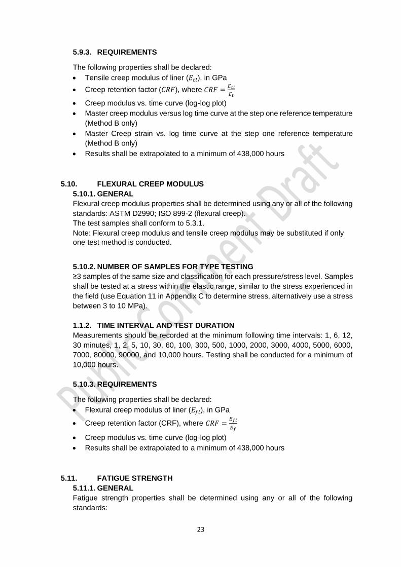
• Tensile creep modulus of liner (𝐸𝑡𝑙), in GPa
• Creep retention factor (𝐶𝑅𝐹), where 𝐶𝑅𝐹 =𝐸𝑡𝑙
𝐸𝑡
• Creep modulus vs. time curve (log-log plot)
• Master creep modulus versus log time curve at the step one reference temperature
(Method B only)
• Master Creep strain vs. log time curve at the step one reference temperature
(Method B only)
• Results shall be extrapolated to a minimum of 438,000 hours
5.10. FLEXURAL CREEP MODULUS
5.10.1. GENERAL
Flexural creep modulus properties shall be determined using any or all of the following
standards: ASTM D2990; ISO 899-2 (flexural creep).
The test samples shall conform to 5.3.1.
Note: Flexural creep modulus and tensile creep modulus may be substituted if only
one test method is conducted.
5.10.2. NUMBER OF SAMPLES FOR TYPE TESTING
≥3 samples of the same size and classification for each pressure/stress level. Samples
shall be tested at a stress within the elastic range, similar to the stress experienced in
the field (use Equation 11 in Appendix C to determine stress, alternatively use a stress
between 3 to 10 MPa).
1.1.2. TIME INTERVAL AND TEST DURATION
Measurements should be recorded at the minimum following time intervals: 1, 6, 12,
30 minutes, 1, 2, 5, 10, 30, 60, 100, 300, 500, 1000, 2000, 3000, 4000, 5000, 6000,
7000, 80000, 90000, and 10,000 hours. Testing shall be conducted for a minimum of
10,000 hours.
5.10.3. REQUIREMENTS
The following properties shall be declared:
• Flexural creep modulus of liner (𝐸𝑓𝑙), in GPa
• Creep retention factor (CRF), where 𝐶𝑅𝐹 =𝐸𝑓𝑙
𝐸𝑓
• Creep modulus vs. time curve (log-log plot)
• Results shall be extrapolated to a minimum of 438,000 hours
5.11. FATIGUE STRENGTH
5.11.1. GENERAL
Fatigue strength properties shall be determined using any or all of the following
standards:
24
Method A (fatigue strength): ISO 13003 with ISO 10928 (regression analysis). Method B (cyclic hydrostatic strength): ASTM D2992; ISO 15306 with ISO 10928 (regression analysis). The test samples shall conform to 5.2.1 (Method A) and 5.4.1 (Method B).
5.11.2. NUMBER OF SAMPLES FOR TYPE TESTING
≥18 samples of the same size and classification shall be used. Minimum number of
cycles to failure points must correspond to those from the above standards (4.11.1).
5.11.3. REQUIREMENTS
The following properties shall be declared:
• Tensile fatigue strength of liner (𝜎𝑡𝑙,𝑓), in GPa
• Fatigue stress vs. number of cycles to failure (log-log plot)
• 97.5% lower confidence limit line
• Regression line and lower confidence line shall be extrapolated to a minimum of
10,000,000 cycles
The properties shall be taken from the lower confidence level of 97.5%.
5.12. TESTING AND CONDITIONING TEMPERATURES
All mechanical characteristics specified in this document shall, unless otherwise
specified, be determined at a temperature of 23 ± 2 °C. For long-term service
temperatures greater than 25 °C, type tests shall, unless otherwise specified, be carried
out within 5 °C of, but at not less than the design service temperature in order to
establish re-rating factors to be used in design.
Humidity (water) can have an impact on spray liners causing the material to plasticise
(lower elastic modulus and lower strength values, with increased ductility). Sample
testing should be conducted in water following AS3862, ASTM D570 or ISO 62 for
saturation times. Saturation times shall be recorded as part of test results. Wet
properties (or dry properties with corrected wet derating factors) shall be used in design.
Test samples shall be tested underwater (with immersion period) (for 5.8, 5.9, 5.10, 5.11),
or samples shall be saturated based on ASTM D570 or ISO 62 saturation times an
immediately tested (for short-term tests, 5.2, 5.3, 5.4). Alternatively, a wet strength
reduction factor, 𝜙𝑠, shall be used where testing is conducted for strength properties (5.2,
5.3, 5.4, 5.8, 5.11) on dry samples and compared with wet samples.
𝜙𝑠 =𝜎𝑡,𝑤𝑒𝑡𝜎𝑡,𝑑𝑟𝑦
where 𝜎𝑡,𝑤𝑒𝑡 is the tensile strength of the liner under wet conditions and 𝜎𝑡,𝑑𝑟𝑦 is the
tensile strength of the liner under dry conditions. The wet strength reduction factor shall
be a factor from 0 to 1.

25
For creep modulus (5.9, 5.10), test samples shall be tested underwater (with immersion
period). A wet creep reduction factor, 𝜙𝑐, shall be used if samples are conducted dry, to
compare with wet samples.
𝜙𝑐 =𝐸𝑙,𝑤𝑒𝑡𝐸𝑙,𝑑𝑟𝑦
𝐸𝑙,𝑤𝑒𝑡 is the creep modulus for wet samples and 𝐸𝑙,𝑑𝑟𝑦 is the creep modulus for dry
samples. The wet creep modulus reduction factor shall be a factor from 0 to 1.
5.13.TEST REQUIREMENTS
When tested in accordance with the methods given in Table A1, the mechanical
characteristics of pipe samples taken from actual or simulated installations shall conform
to these tables.
Testing standards and sample type/size used shall be declared.
Where requirements are specified in Sections 5.2 to 5.12 and Table A1 are declared
values, these declarations shall be documented for each liner product, with supporting
test data or references to such data, in the installation manual for that product.
The extensions into the lateral pipe of Class A, B and C lateral connection collars shall
be considered as pipes.
Declared values refer to the 97.5% lower confidence limit value of the test results as
determined from the results of tests on a set of the specified number of test samples.
Other international or national Standard tests may be applied where the test conditions
are identical to the nominated methods or sufficiently similar as to produce essentially
equivalent results.
6. SAMPLING
The supplier shall document the method used for acquiring samples for testing for
installation quality control purposes. The samples may be obtained by means of one of
the following methods:
(i) a simulated installation;
(ii) an installation; or
(iii) any other method that can be demonstrated to replicate the characteristics of samples
cut from the actual pipe wall.
The test requirements and associated standards are listed in Section 5.2 to 5.12 and
Appendix A, Table A1
7. ADDITIONAL CHARACTERISTICS
7.1. RECONNECTION TO THE EXISTING NETWORK

26
The supplier shall provide detailed written instructions regarding the type of end seals and any connection fittings to be used when connecting the cured lined pipe to the existing water network. All terminations shall be water tight when tested in accordance with AS/NZS 2566.2, Section 6. Refer Manual for selection and application of cured-in-place pipe (CIPP) and spray liners for use in water pipe for additional requirements.
7.2. RECONNECTION OF EXISTING SERVICES
For spray liners, service connection and lateral reinstatement should not be required, unless a blockage occurs. Where a blockage occurs reinstatement of the service or lateral should follow the guidelines outlined in the Manual for selection and application of cured-in-place pipe (CIPP) and spray liners for use in water pipe. Reinstated service connections shall be water tight as per AS/NZS 2566.2, Section 6.
7.3. CONNECTION OF NEW SERVICES
The supplier shall provide detailed written instructions regarding the connection of new
services to a pipeline renovated using the spray liner product. The method of connecting
new services may vary based on the host pipe material and class requirements of the liner.
7.4. CONNECTION OF NEW OFFTAKES
The supplier shall provide detailed written instructions regarding the connection of new
offtakes to pipeline renovated using the spray lining product. The method of connecting
new offtake may vary based on the host pipe material and class requirements of the liner.
7.5. REPAIR OF RENOVATED PIPELINE
The supplier shall provide detailed written instructions regarding the repair of pipelines
renovated using the spray lining product. The method of repair may vary based on the host
pipe material and class requirements of the liner.
7.6. CHEMICAL RESISTANCE
The liner shall have chemical resistance to the solution used in the disinfection of water
pipelines, which is 20 ppm of free chlorine.
7.7. OTHER
The supplier shall nominate any other requirements for the successful installation of their
product.
8. PRODUCT DOCUMENTATION
8.1. GENERAL
Technical information relating to the spray lining system and correct installation methods
shall be readily available to aid the user and installer. The information may be in the form
of a technical manual or equivalent document and be written in plain English and
supplemented by figures and diagrams as applicable. The information provided shall satisfy

27
the requirements of a warranty as referenced in the Plumbing Code of Australia (PCA) and
those requirements of the AS/NZS 3500 series of Standards.
The information shall consider the requirements in the WSAA Manual for selection and
application of cured-in-place pipe (CIPP) and spray liners for use in water pipe. Where
deviation from the requirements of this manual is necessary this shall be highlighted for the
review and approval of the asset owner.
8.2. PRODUCT DATA
Product data shall be available that identifies critical product characteristics and as a
minimum include
a) Diameter range for application.
b) Pipe length range for application.
c) Minimum and maximum overcoat times (for multi-layer applications).
d) Safety Data Sheets (SDS).
e) Details of the maximum hole and gap spanning ability of the product.
f) The structural capabilities of the product in accordance with Appendix B.
g) OHS requirements.
h) Any derating factors to be applied to physical characteristics measured under
laboratory conditions when designing a pipeline renovation.
8.3. INSTALLATION INSTRUCTIONS
The manufacturer shall provide installation instructions including, but not limited to, details
of:
a) Equipment to be used, e.g. type of spray lining rig.
b) Preparatory works, e.g. obstruction removal, surface cleaning.
c) Handling and installation details.
d) The mixing ratio of the components by mass or volume as appropriate, including
the acceptable ratio tolerance.
e) The temperature band within which the components and blend must be
maintained.
f) Working time, i.e. the time within which the mixed resin system must be installed.
g) Curing times and whether these are thickness dependent.
h) Maximum and minimum curing temperatures.
i) Any restrictions on the site ambient conditions that might adversely affect the
application of the lining.
j) Minimum and maximum thickness to be applied with each pass and time interval
permitted between multiple passes.
k) Liner termination procedure required to avoid leakage.
l) Procedure to avoid leakage at connections including tapping bands and under
pressure cut-ins.
m) Final inspection and testing.
n) Requirements for new offtakes and new services.
o) Requirements for repair of lined pipeline.
p) Expected blockage rate for service connections.
NOTES:
28
1. Where appropriate, a derating factor may be applied to short-term physical
properties in order to estimate long-term characteristics. Where the material
properties are temperature sensitive, a temperature-derating factor may be
required when the renovated pipe is subjected to elevated service temperatures.
Where material properties are sensitive to water saturation or humidity, a water
derating factor shall be required.
2. When pipes have CML water can migrate through the CML when under pressure.
Additional steps may be required to prevent leakage when CML is present.
29
APPENDIX A
MEANS FOR DEMONSTRATING CONFORMITY WITH THIS STANDARD
(Normative)
A1 SCOPE
This Appendix sets out a means for consistent demonstration of conformity with this
Standard through the use of a minimum sampling and testing frequency plan. Where
variations to this plan are made, demonstration of conformance with the minimum
requirements may be necessary.
A2 RELEVANCE
The long-term performance of pipeline systems is critical to the operating efficiency of water
agencies in terms of operating licences and customer contracts. The long-term performance
of plumbing systems is similarly critical to the durability of building infrastructure, protection
of public health and safety and protection of the environment.
A3 DEFINITIONS
A3.1 Acceptable quality level (AQL)
When a continuous series of lots or batches is considered, the quality level which, for the
purpose of sampling inspection, is the limit of a satisfactory process average (see AS
1199.1).
NOTE: The designation of an AQL does not imply that a manufacturer has the right knowingly to
supply any non-conforming unit of product.
A3.2 Material or compound batch
A clearly identifiable quantity of a particular material or compound.
A3.3 Production batch
A clearly identifiable collection of units, manufactured consecutively or continuously under
the same conditions, using material or compound to the same specification.
A3.4 Lot
A clearly identifiable subdivision of a batch for inspection purposes.
A3.5 Sample
One or more units of product drawn from a batch or lot, selected at random without regard to
quality.
NOTE: The number of units of product in the sample is the sample size.
A3.6 Sampling plan
A specific plan, indicating the number of units of components or assemblies to be inspected
or tested.
A3.7 Process verification test (PVT)
30
A test performed by the manufacturer on materials, components, joints or assemblies at
specific intervals to confirm that the process continues to be capable of producing
components conforming to the requirements of the relevant Standard.
NOTE: Such tests are not required to release batches of components and are carried out as a
measure of process control.
A3.8 Batch release test (BRT)
A test performed by the manufacturer on a batch of components, which has to be
satisfactorily completed before the batch can be released.
A3.9 Type testing (TT)
Testing performed to prove that the material, component, joint or assembly is capable of
conforming to the requirements of the relevant Standard.
A4 MINIMUM SAMPLING AND TESTING FREQUENCY PLAN
A4.1 General
Table A1 sets out the minimum sampling and testing frequency plan for a manufacturer to
demonstrate compliance to this Standard. Where variations to this plan are made,
demonstration of conformance with the minimum requirements may be necessary.
A4.2 Testing
Testing shall be conducted by a testing laboratory or facility that fulfills the requirements of
AS ISO/IEC 17025, General requirements for the competence of testing and calibration
laboratories.
NOTE: AS ISO/IEC 17025 can apply to first-party, i.e. manufacturer or supplier, second-party or third-
party testing laboratories and facilities.
A4.3 Retesting
In the event of a test failure, the products manufactured since the previous test(s)
conforming to the requirements outlined in Table ZA1 shall be quarantined as a batch. A
further set of samples shall be selected randomly from the quarantined batch using a
sampling plan to AS 1199.1. If the retest requirements are met, the batch may be released
and compliance with this Standard for the quarantined batch may be claimed.
Should a failure on retesting occur, then the quarantined batch shall be rejected and claims
and/or marking indicating conformity to this Standard shall be suspended until the cause of
the failure has been identified and corrected.
A4.4 Rejection after retest
In the event of a quarantined batch being rejected after retesting, it may be subjected to
100% testing for the failed requirement(s), and only those items found to comply may be
claimed and/or marked as conforming with this standard.

31
TABLE A1 MINIMUM SAMPLING AND TESTING FREQUENCY PLAN
Characteristic Clause Requirement Test Method Frequency
MATERIAL PROPERTIES FOR RESIN SYSTEM
Resin type 2.1.2, Table 1 PU, PEUU, or EP Declared value
At any change in material formulation, design or process
Filler type 2.1.2, Table 1 None, inorganic or organic
Declared value
Curing agent type 2.1.2, Table 1 Heat-initiated, light-initiated, or ambient cure
Declared value
PROPERTIES OF RESIN COMPONENTS (UNCURED)
Density Table 2 Declared value Declared value
At any change in material formulation, design or process. Test results considered valid for 5 years.
Colour 2.1.1 Declared value Visual inspection
PROPERTIES OF CURED RESIN
Glass transition temperature
Table 3 Recorded value ASTM D7028-07 or ISO 11359-2-99 At any change in
material formulation, design or process. Test results considered valid for 5 years.
Water absorption Table 3 Recorded value AS3862
Contact with drinking water Table 3
Must pass AS/NZS 4020 requirements
AS/NZS 4020
Liner thickness 3.5 Varies by method refer clause 3.5
Clause 3.5 Varies by method refer clause 3.5
PERFORMANCE REQUIREMENTS
Surface irregularities
3.3 Average thickness not exceeded by ±10%
Visual inspection - Post CCTV inspection
Every installation
Hole spanning 3.4 Spans up to 3mm diameter holes
See Section 3.4
At any change in material formulation, design or process. Test results considered valid for 5 years.
Gap spanning 3.4 Spans up to 3mm gaps, width and depth
See Section 3.4
Water tightness 2.4.6 All fittings, terminations and connections are water tight
AS/NZS 2566.2, Section 6
As per water agency testing frequency requirements
Contact with drinking water
2.4.2 Table 3 3.2 4.1
All system components meet standard requirements
AS/NZS 4020
At any change in material formulation, design or process. Test results considered valid for 5 years.
Elastomeric seals 4.1
Compliance with AS 1646 and AS 681.1
Product certification to AS 1646 and AS 681.1
32
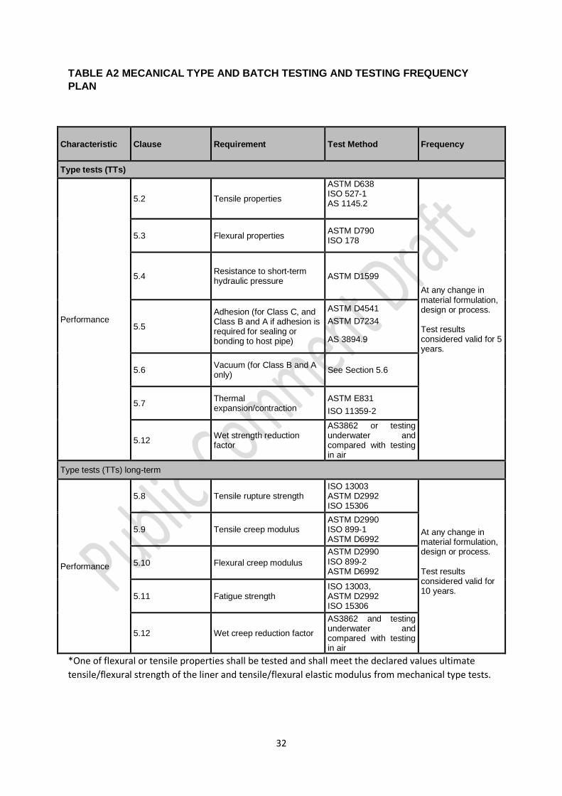
TABLE A2 MECANICAL TYPE AND BATCH TESTING AND TESTING FREQUENCY
PLAN
Characteristic Clause Requirement Test Method Frequency
Type tests (TTs)
Performance
5.2 Tensile properties
ASTM D638 ISO 527-1 AS 1145.2
At any change in material formulation, design or process. Test results considered valid for 5 years.
5.3 Flexural properties ASTM D790 ISO 178
5.4 Resistance to short-term hydraulic pressure
ASTM D1599
5.5
Adhesion (for Class C, and Class B and A if adhesion is required for sealing or bonding to host pipe)
ASTM D4541
ASTM D7234
AS 3894.9
5.6 Vacuum (for Class B and A only)
See Section 5.6
5.7 Thermal expansion/contraction
ASTM E831
ISO 11359-2
5.12 Wet strength reduction factor
AS3862 or testing underwater and compared with testing in air
Type tests (TTs) long-term
Performance
5.8 Tensile rupture strength ISO 13003 ASTM D2992 ISO 15306
At any change in material formulation, design or process. Test results considered valid for 10 years.
5.9 Tensile creep modulus ASTM D2990 ISO 899-1 ASTM D6992
5.10 Flexural creep modulus
ASTM D2990 ISO 899-2 ASTM D6992
5.11 Fatigue strength ISO 13003, ASTM D2992 ISO 15306
5.12 Wet creep reduction factor
AS3862 and testing underwater and compared with testing in air
*One of flexural or tensile properties shall be tested and shall meet the declared values ultimate
tensile/flexural strength of the liner and tensile/flexural elastic modulus from mechanical type tests.

33
APPENDIX B
(Normative)
STRUCTURAL CLASSIFICATION OF LINERS
Piping systems used for the renovation of pressure pipelines are classified in ISO 11295 in
accordance with their structural performance as follows.
B1 CLASS A (Note this Class of pipe is not included in this WSAA Standard)
i. Can survive internally or externally induced failure of the host pipe.
ii. The long-term pressure rating is equal to or greater than the maximum allowable
operating pressure of the renovated pipeline.
iii. The liner has sufficient inherent ring stiffness to be self-supporting when
depressurised.
iv. Is capable of spanning gaps and holes long-term at the maximum allowable
operating pressure.
v. Provides an internal barrier to the corrosion, abrasion and/or tuberculation / scaling of
the host pipe and to the contamination of the pipe contents by the host pipe.
Generally it also reduces the surface roughness for improved hydraulic performance.
B2 CLASS B
i. The liner has sufficient inherent ring stiffness to be self-supporting when
depressurised.
ii. Is capable of spanning gaps and holes long-term at the maximum allowable
operating pressure.
NOTE: The liner becomes sufficiently close fit during installation or during initial
operation for transfer of the internal pressure stress to the host pipe.
iii. Provides an internal barrier to the corrosion, abrasion and/or tuberculation / scaling of
the host pipe and to the contamination of the pipe contents by the host pipe.
Generally it also reduces the surface roughness for improved hydraulic performance.
B3 CLASS C
i. The liner relies on adhesion to the host pipe to be self-supporting when
depressurised.
ii. Is capable of spanning gaps and holes long-term at the maximum allowable
operating pressure.
NOTE: The liner becomes sufficiently close fit during installation or during initial
operation for transfer of the internal pressure stress to the host pipe.
iii. Provides an internal barrier to the corrosion, abrasion and/or tuberculation / scaling of
the host pipe and to the contamination of the pipe contents by the host pipe.
Generally it also reduces the surface roughness for improved hydraulic performance.
B4 CLASS D
i. The liner relies on adhesion to the host pipe to be self-supporting when
depressurised.
ii. Provides an internal barrier to the corrosion, abrasion and/or tuberculation / scaling of
the host pipe and to the contamination of the pipe contents by the host pipe.
Generally it also reduces the surface roughness for improved hydraulic performance.
34
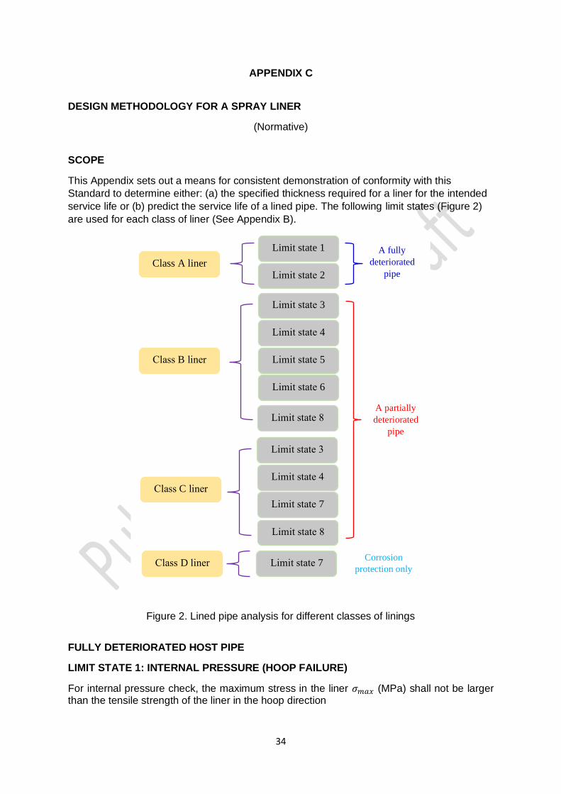
APPENDIX C
DESIGN METHODOLOGY FOR A SPRAY LINER
(Normative)
SCOPE
This Appendix sets out a means for consistent demonstration of conformity with this
Standard to determine either: (a) the specified thickness required for a liner for the intended
service life or (b) predict the service life of a lined pipe. The following limit states (Figure 2)
are used for each class of liner (See Appendix B).
Figure 2. Lined pipe analysis for different classes of linings
FULLY DETERIORATED HOST PIPE
LIMIT STATE 1: INTERNAL PRESSURE (HOOP FAILURE)
For internal pressure check, the maximum stress in the liner 𝜎𝑚𝑎𝑥 (MPa) shall not be larger than the tensile strength of the liner in the hoop direction
Class A liner
Limit state 1
Class B liner
Class C liner
Class D liner
Limit state 2
Limit state 4
Limit state 5
Limit state 3
Limit state 6
Limit state 4
Limit state 7
Limit state 3
Limit state 7
A fully
deteriorated
pipe
A partially
deteriorated
pipe
Corrosion
protection only
Limit state 8
Limit state 8
35
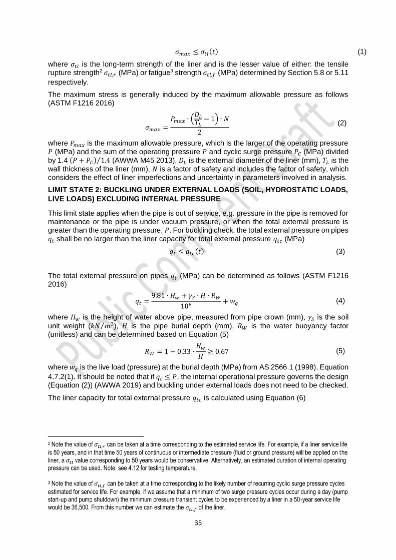
𝜎𝑚𝑎𝑥 ≤ 𝜎𝑡𝑙(𝑡) (1)
where 𝜎𝑡𝑙 is the long-term strength of the liner and is the lesser value of either: the tensile rupture strength2 𝜎𝑡𝑙,𝑟 (MPa) or fatigue3 strength 𝜎𝑡𝑙,𝑓 (MPa) determined by Section 5.8 or 5.11
respectively.
The maximum stress is generally induced by the maximum allowable pressure as follows (ASTM F1216 2016)
𝜎𝑚𝑎𝑥 =𝑃𝑚𝑎𝑥 ∙ (
𝐷𝐿𝑇𝐿
− 1) ∙ 𝑁
2
(2)
where 𝑃𝑚𝑎𝑥 is the maximum allowable pressure, which is the larger of the operating pressure
𝑃 (MPa) and the sum of the operating pressure 𝑃 and cyclic surge pressure 𝑃𝐶 (MPa) divided
by 1.4 (𝑃 + 𝑃𝐶) 1.4⁄ (AWWA M45 2013), 𝐷𝐿 is the external diameter of the liner (mm), 𝑇𝐿 is the
wall thickness of the liner (mm), 𝑁 is a factor of safety and includes the factor of safety, which considers the effect of liner imperfections and uncertainty in parameters involved in analysis.
LIMIT STATE 2: BUCKLING UNDER EXTERNAL LOADS (SOIL, HYDROSTATIC LOADS,
LIVE LOADS) EXCLUDING INTERNAL PRESSURE
This limit state applies when the pipe is out of service, e.g. pressure in the pipe is removed for maintenance or the pipe is under vacuum pressure, or when the total external pressure is greater than the operating pressure, 𝑃. For buckling check, the total external pressure on pipes
𝑞𝑡 shall be no larger than the liner capacity for total external pressure 𝑞𝑡𝑐 (MPa)
𝑞𝑡 ≤ 𝑞𝑡𝑐(𝑡) (3)
The total external pressure on pipes 𝑞𝑡 (MPa) can be determined as follows (ASTM F1216 2016)
𝑞𝑡 =9.81 ∙ 𝐻𝑤 + 𝛾𝑆 ∙ 𝐻 ∙ 𝑅𝑊
106+ 𝑤𝑞 (4)
where 𝐻𝑤 is the height of water above pipe, measured from pipe crown (mm), 𝛾𝑆 is the soil
unit weight (𝑘𝑁 𝑚3⁄ ), 𝐻 is the pipe burial depth (mm), 𝑅𝑊 is the water buoyancy factor (unitless) and can be determined based on Equation (5)
𝑅𝑊 = 1 − 0.33 ∙𝐻𝑤𝐻
≥ 0.67 (5)
where 𝑤𝑞 is the live load (pressure) at the burial depth (MPa) from AS 2566.1 (1998), Equation
4.7.2(1). It should be noted that if 𝑞𝑡 ≤ 𝑃, the internal operational pressure governs the design (Equation (2)) (AWWA 2019) and buckling under external loads does not need to be checked.
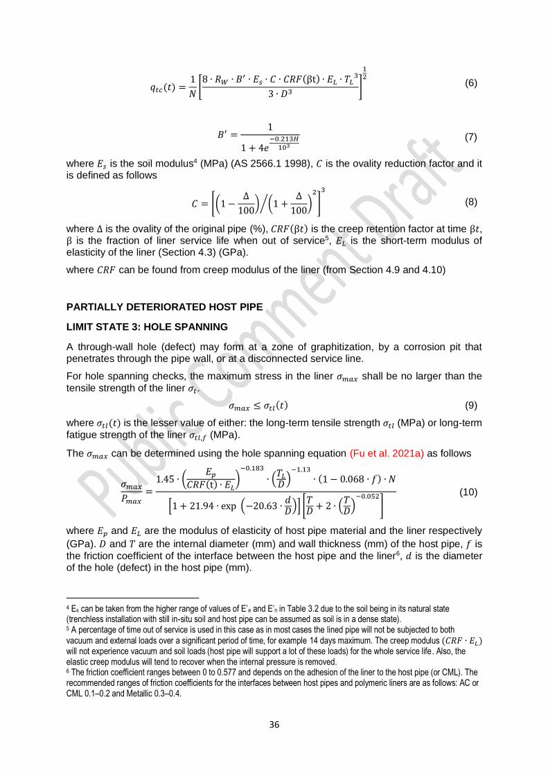
The liner capacity for total external pressure 𝑞𝑡𝑐 is calculated using Equation (6)
2 Note the value of 𝜎𝑡𝑙,𝑟 can be taken at a time corresponding to the estimated service life. For example, if a liner service life
is 50 years, and in that time 50 years of continuous or intermediate pressure (fluid or ground pressure) will be applied on the liner, a 𝜎𝑡𝑙 value corresponding to 50 years would be conservative. Alternatively, an estimated duration of internal operating pressure can be used. Note: see 4.12 for testing temperature. 3 Note the value of 𝜎𝑡𝑙,𝑓 can be taken at a time corresponding to the likely number of recurring cyclic surge pressure cycles
estimated for service life. For example, if we assume that a minimum of two surge pressure cycles occur during a day (pump start-up and pump shutdown) the minimum pressure transient cycles to be experienced by a liner in a 50-year service life would be 36,500. From this number we can estimate the 𝜎𝑡𝑙,𝑓 of the liner.
36
𝑞𝑡𝑐(𝑡) =1
𝑁[8 ∙ 𝑅𝑊 ∙ 𝐵′ ∙ 𝐸𝑠 ∙ 𝐶 ∙ 𝐶𝑅𝐹(βt) ∙ 𝐸𝐿 ∙ 𝑇𝐿
3
3 ∙ 𝐷3]
12
(6)
𝐵′ =1
1 + 4𝑒−0.213𝐻
103
(7)
where 𝐸𝑠 is the soil modulus4 (MPa) (AS 2566.1 1998), 𝐶 is the ovality reduction factor and it is defined as follows
𝐶 = [(1−∆
100) (1 +
∆
100)2
⁄ ]
3
(8)
where ∆ is the ovality of the original pipe (%), 𝐶𝑅𝐹(β𝑡) is the creep retention factor at time β𝑡, β is the fraction of liner service life when out of service5, 𝐸𝐿 is the short-term modulus of elasticity of the liner (Section 4.3) (GPa).
where 𝐶𝑅𝐹 can be found from creep modulus of the liner (from Section 4.9 and 4.10)
PARTIALLY DETERIORATED HOST PIPE
LIMIT STATE 3: HOLE SPANNING
A through-wall hole (defect) may form at a zone of graphitization, by a corrosion pit that penetrates through the pipe wall, or at a disconnected service line.
For hole spanning checks, the maximum stress in the liner 𝜎𝑚𝑎𝑥 shall be no larger than the
tensile strength of the liner 𝜎𝑡.
𝜎𝑚𝑎𝑥 ≤ 𝜎𝑡𝑙(𝑡) (9)
where 𝜎𝑡𝑙(𝑡) is the lesser value of either: the long-term tensile strength 𝜎𝑡𝑙 (MPa) or long-term
fatigue strength of the liner 𝜎𝑡𝑙,𝑓 (MPa).
The 𝜎𝑚𝑎𝑥 can be determined using the hole spanning equation (Fu et al. 2021a) as follows
𝜎𝑚𝑎𝑥
𝑃𝑚𝑎𝑥=1.45 ∙ (
𝐸𝑝𝐶𝑅𝐹(t) ∙ 𝐸𝐿
)−0.183
∙ (𝑇𝐿𝐷)−1.13
∙ (1 − 0.068 ∙ 𝑓) ∙ 𝑁
[1+ 21.94 ∙ exp (−20.63 ∙𝑑𝐷)] [
𝑇𝐷 + 2 ∙ (
𝑇𝐷)−0.052
]
(10)
where 𝐸𝑝 and 𝐸𝐿 are the modulus of elasticity of host pipe material and the liner respectively
(GPa). 𝐷 and 𝑇 are the internal diameter (mm) and wall thickness (mm) of the host pipe, 𝑓 is
the friction coefficient of the interface between the host pipe and the liner6, 𝑑 is the diameter of the hole (defect) in the host pipe (mm).
4 Es can be taken from the higher range of values of E’e and E’n in Table 3.2 due to the soil being in its natural state (trenchless installation with still in-situ soil and host pipe can be assumed as soil is in a dense state). 5 A percentage of time out of service is used in this case as in most cases the lined pipe will not be subjected to both vacuum and external loads over a significant period of time, for example 14 days maximum. The creep modulus (𝐶𝑅𝐹 ∙ 𝐸𝐿) will not experience vacuum and soil loads (host pipe will support a lot of these loads) for the whole service life. Also, the elastic creep modulus will tend to recover when the internal pressure is removed. 6 The friction coefficient ranges between 0 to 0.577 and depends on the adhesion of the liner to the host pipe (or CML). The recommended ranges of friction coefficients for the interfaces between host pipes and polymeric liners are as follows: AC or CML 0.1–0.2 and Metallic 0.3–0.4.
37
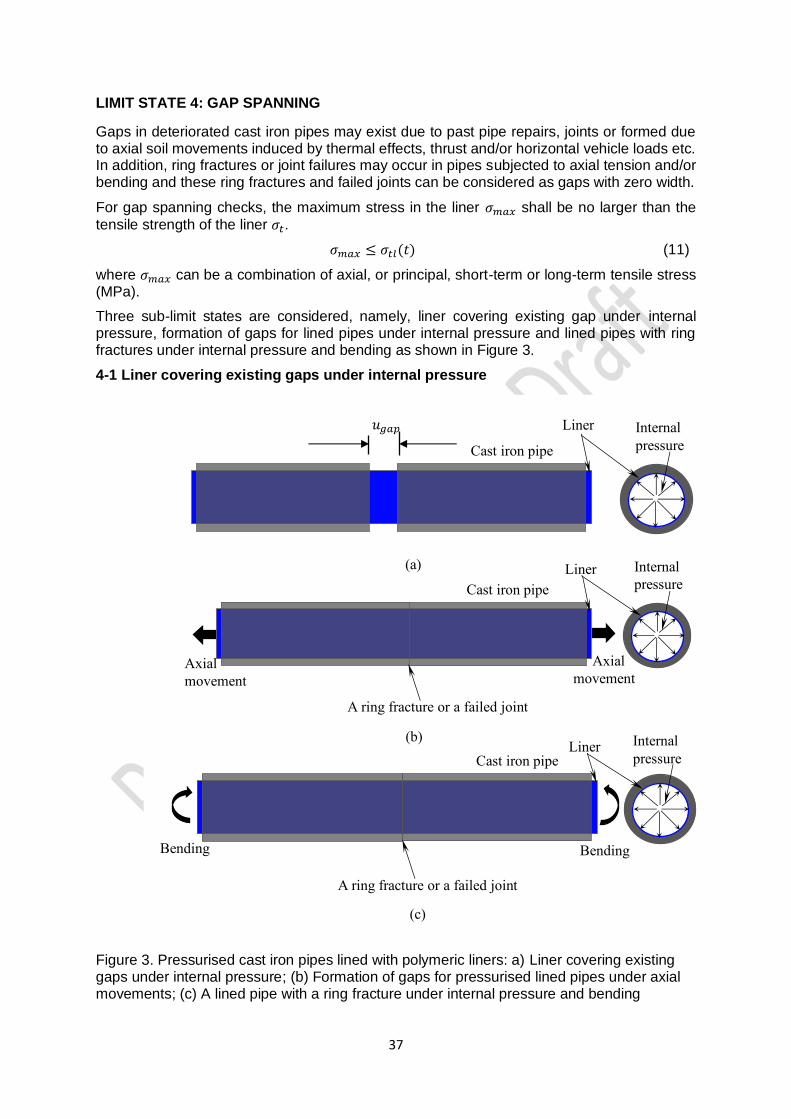
LIMIT STATE 4: GAP SPANNING
Gaps in deteriorated cast iron pipes may exist due to past pipe repairs, joints or formed due to axial soil movements induced by thermal effects, thrust and/or horizontal vehicle loads etc. In addition, ring fractures or joint failures may occur in pipes subjected to axial tension and/or bending and these ring fractures and failed joints can be considered as gaps with zero width.
For gap spanning checks, the maximum stress in the liner 𝜎𝑚𝑎𝑥 shall be no larger than the
tensile strength of the liner 𝜎𝑡.
𝜎𝑚𝑎𝑥 ≤ 𝜎𝑡𝑙(𝑡) (11)
where 𝜎𝑚𝑎𝑥 can be a combination of axial, or principal, short-term or long-term tensile stress (MPa).
Three sub-limit states are considered, namely, liner covering existing gap under internal pressure, formation of gaps for lined pipes under internal pressure and lined pipes with ring fractures under internal pressure and bending as shown in Figure 3.
4-1 Liner covering existing gaps under internal pressure
Figure 3. Pressurised cast iron pipes lined with polymeric liners: a) Liner covering existing gaps under internal pressure; (b) Formation of gaps for pressurised lined pipes under axial movements; (c) A lined pipe with a ring fracture under internal pressure and bending
𝑢𝑔𝑎𝑝
Cast iron pipe
Liner
(a)
Cast iron pipe
Liner
A ring fracture or a failed joint
Axial
movement
Axial
movement
(b)
Cast iron pipe Liner
Bending Bending
A ring fracture or a failed joint
(c)
Internal
pressure
Internal
pressure
Internal
pressure
38
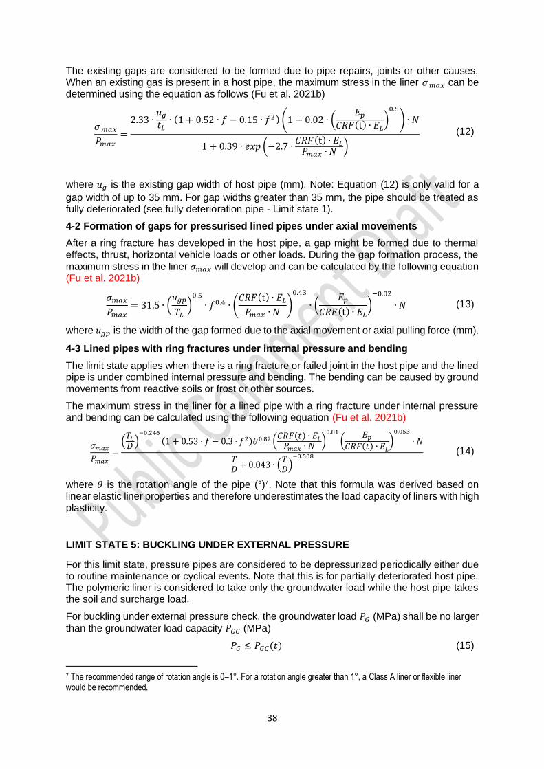
The existing gaps are considered to be formed due to pipe repairs, joints or other causes. When an existing gas is present in a host pipe, the maximum stress in the liner 𝜎𝑚𝑎𝑥 can be determined using the equation as follows (Fu et al. 2021b)
𝜎𝑚𝑎𝑥
𝑃𝑚𝑎𝑥=
2.33 ∙𝑢𝑔𝑡𝐿
∙ (1 + 0.52 ∙ 𝑓 − 0.15 ∙ 𝑓2) (1 − 0.02 ∙ (𝐸𝑝
𝐶𝑅𝐹(t) ∙ 𝐸𝐿)0.5
) ∙ 𝑁
1 + 0.39 ∙ 𝑒𝑥𝑝 (−2.7 ∙𝐶𝑅𝐹(t) ∙ 𝐸𝐿𝑃𝑚𝑎𝑥 ∙ 𝑁
) (12)
where 𝑢𝑔 is the existing gap width of host pipe (mm). Note: Equation (12) is only valid for a
gap width of up to 35 mm. For gap widths greater than 35 mm, the pipe should be treated as fully deteriorated (see fully deterioration pipe - Limit state 1).
4-2 Formation of gaps for pressurised lined pipes under axial movements
After a ring fracture has developed in the host pipe, a gap might be formed due to thermal effects, thrust, horizontal vehicle loads or other loads. During the gap formation process, the
maximum stress in the liner 𝜎𝑚𝑎𝑥 will develop and can be calculated by the following equation (Fu et al. 2021b)
𝜎𝑚𝑎𝑥
𝑃𝑚𝑎𝑥= 31.5 ∙ (
𝑢𝑔𝑝
𝑇𝐿)0.5
∙ 𝑓0.4 ∙ (𝐶𝑅𝐹(t) ∙ 𝐸𝐿𝑃𝑚𝑎𝑥 ∙ 𝑁
)
0.43
∙ (𝐸𝑝
𝐶𝑅𝐹(t) ∙ 𝐸𝐿)−0.02
∙ 𝑁 (13)
where 𝑢𝑔𝑝 is the width of the gap formed due to the axial movement or axial pulling force (mm).
4-3 Lined pipes with ring fractures under internal pressure and bending
The limit state applies when there is a ring fracture or failed joint in the host pipe and the lined pipe is under combined internal pressure and bending. The bending can be caused by ground movements from reactive soils or frost or other sources.
The maximum stress in the liner for a lined pipe with a ring fracture under internal pressure and bending can be calculated using the following equation (Fu et al. 2021b)
𝜎𝑚𝑎𝑥
𝑃𝑚𝑎𝑥
=(𝑇𝐿𝐷)
−0.246
(1 + 0.53 ∙ 𝑓 − 0.3 ∙ 𝑓2)𝜃0.82 (𝐶𝑅𝐹(𝑡) ∙ 𝐸𝐿𝑃𝑚𝑎𝑥 ∙ 𝑁
)0.81
(𝐸𝑝
𝐶𝑅𝐹(𝑡) ∙ 𝐸𝐿)0.053
∙ 𝑁
𝑇𝐷 + 0.043 ∙ (
𝑇𝐷)
−0.508 (14)
where 𝜃 is the rotation angle of the pipe (°)7. Note that this formula was derived based on linear elastic liner properties and therefore underestimates the load capacity of liners with high plasticity.
LIMIT STATE 5: BUCKLING UNDER EXTERNAL PRESSURE
For this limit state, pressure pipes are considered to be depressurized periodically either due to routine maintenance or cyclical events. Note that this is for partially deteriorated host pipe. The polymeric liner is considered to take only the groundwater load while the host pipe takes the soil and surcharge load.
For buckling under external pressure check, the groundwater load 𝑃𝐺 (MPa) shall be no larger
than the groundwater load capacity 𝑃𝐺𝐶 (MPa)
𝑃𝐺 ≤ 𝑃𝐺𝐶(𝑡) (15)
7 The recommended range of rotation angle is 0–1°. For a rotation angle greater than 1°, a Class A liner or flexible liner would be recommended.
39
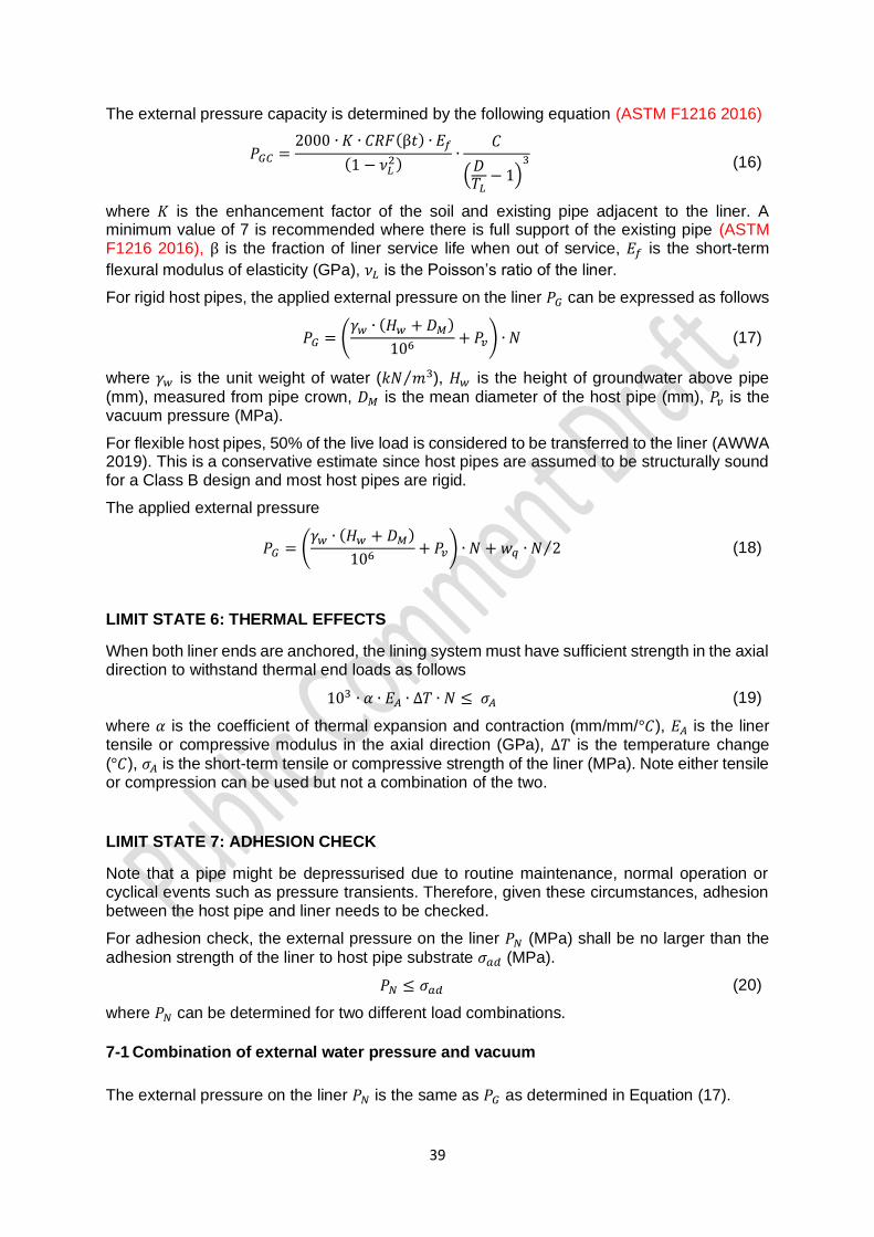
The external pressure capacity is determined by the following equation (ASTM F1216 2016)
𝑃𝐺𝐶 =2000 ∙ 𝐾 ∙ 𝐶𝑅𝐹(β𝑡) ∙ 𝐸𝑓
(1 − 𝜈𝐿2)
∙𝐶
(𝐷𝑇𝐿
− 1)3
(16)
where 𝐾 is the enhancement factor of the soil and existing pipe adjacent to the liner. A minimum value of 7 is recommended where there is full support of the existing pipe (ASTM F1216 2016), β is the fraction of liner service life when out of service, 𝐸𝑓 is the short-term
flexural modulus of elasticity (GPa), 𝜈𝐿 is the Poisson’s ratio of the liner.
For rigid host pipes, the applied external pressure on the liner 𝑃𝐺 can be expressed as follows
𝑃𝐺 = (𝛾𝑤 ∙ (𝐻𝑤 +𝐷𝑀)
106+ 𝑃𝑣) ∙ 𝑁 (17)
where 𝛾𝑤 is the unit weight of water (𝑘𝑁 𝑚3⁄ ), 𝐻𝑤 is the height of groundwater above pipe
(mm), measured from pipe crown, 𝐷𝑀 is the mean diameter of the host pipe (mm), 𝑃𝑣 is the vacuum pressure (MPa).
For flexible host pipes, 50% of the live load is considered to be transferred to the liner (AWWA 2019). This is a conservative estimate since host pipes are assumed to be structurally sound for a Class B design and most host pipes are rigid.
The applied external pressure
𝑃𝐺 = (𝛾𝑤 ∙ (𝐻𝑤 + 𝐷𝑀)
106+ 𝑃𝑣) ∙ 𝑁 + 𝑤𝑞 ∙ 𝑁 2⁄ (18)
LIMIT STATE 6: THERMAL EFFECTS
When both liner ends are anchored, the lining system must have sufficient strength in the axial direction to withstand thermal end loads as follows
103 ∙ 𝛼 ∙ 𝐸𝐴 ∙ ∆𝑇 ∙ 𝑁 ≤ 𝜎𝐴 (19)
where 𝛼 is the coefficient of thermal expansion and contraction (mm/mm/°𝐶), 𝐸𝐴 is the liner tensile or compressive modulus in the axial direction (GPa), ∆𝑇 is the temperature change
(°𝐶), 𝜎𝐴 is the short-term tensile or compressive strength of the liner (MPa). Note either tensile or compression can be used but not a combination of the two.
LIMIT STATE 7: ADHESION CHECK
Note that a pipe might be depressurised due to routine maintenance, normal operation or cyclical events such as pressure transients. Therefore, given these circumstances, adhesion between the host pipe and liner needs to be checked.
For adhesion check, the external pressure on the liner 𝑃𝑁 (MPa) shall be no larger than the
adhesion strength of the liner to host pipe substrate 𝜎𝑎𝑑 (MPa).
𝑃𝑁 ≤ 𝜎𝑎𝑑 (20)
where 𝑃𝑁 can be determined for two different load combinations.
7-1 Combination of external water pressure and vacuum
The external pressure on the liner 𝑃𝑁 is the same as 𝑃𝐺 as determined in Equation (17).
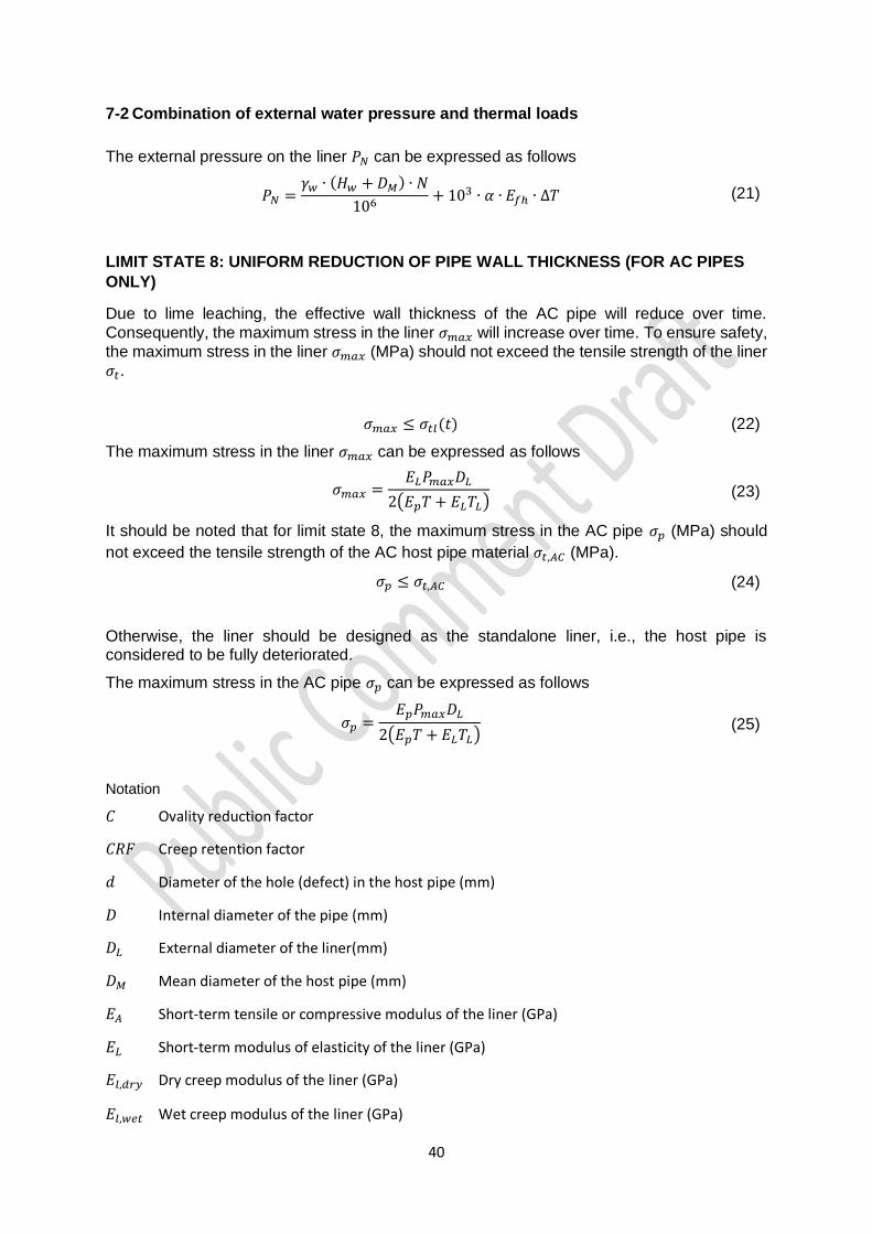
40
7-2 Combination of external water pressure and thermal loads
The external pressure on the liner 𝑃𝑁 can be expressed as follows
𝑃𝑁 =𝛾𝑤 ∙ (𝐻𝑤 +𝐷𝑀) ∙ 𝑁
106+ 103 ∙ 𝛼 ∙ 𝐸𝑓ℎ ∙ ∆𝑇 (21)
LIMIT STATE 8: UNIFORM REDUCTION OF PIPE WALL THICKNESS (FOR AC PIPES
ONLY)
Due to lime leaching, the effective wall thickness of the AC pipe will reduce over time.
Consequently, the maximum stress in the liner 𝜎𝑚𝑎𝑥 will increase over time. To ensure safety,
the maximum stress in the liner 𝜎𝑚𝑎𝑥 (MPa) should not exceed the tensile strength of the liner
𝜎𝑡.
𝜎𝑚𝑎𝑥 ≤ 𝜎𝑡𝑙(𝑡) (22)
The maximum stress in the liner 𝜎𝑚𝑎𝑥 can be expressed as follows
𝜎𝑚𝑎𝑥 =𝐸𝐿𝑃𝑚𝑎𝑥𝐷𝐿
2(𝐸𝑝𝑇 + 𝐸𝐿𝑇𝐿) (23)
It should be noted that for limit state 8, the maximum stress in the AC pipe 𝜎𝑝 (MPa) should
not exceed the tensile strength of the AC host pipe material 𝜎𝑡,𝐴𝐶 (MPa).
𝜎𝑝 ≤ 𝜎𝑡,𝐴𝐶 (24)
Otherwise, the liner should be designed as the standalone liner, i.e., the host pipe is considered to be fully deteriorated.
The maximum stress in the AC pipe 𝜎𝑝 can be expressed as follows
𝜎𝑝 =𝐸𝑝𝑃𝑚𝑎𝑥𝐷𝐿
2(𝐸𝑝𝑇 + 𝐸𝐿𝑇𝐿) (25)
Notation
𝐶 Ovality reduction factor
𝐶𝑅𝐹 Creep retention factor
𝑑 Diameter of the hole (defect) in the host pipe (mm)
𝐷 Internal diameter of the pipe (mm)
𝐷𝐿 External diameter of the liner(mm)
𝐷𝑀 Mean diameter of the host pipe (mm)
𝐸𝐴 Short-term tensile or compressive modulus of the liner (GPa)
𝐸𝐿 Short-term modulus of elasticity of the liner (GPa)
𝐸𝑙,𝑑𝑟𝑦 Dry creep modulus of the liner (GPa)
𝐸𝑙,𝑤𝑒𝑡 Wet creep modulus of the liner (GPa)
41
𝐸𝑓 Short-term flexural modulus of elasticity of the liner (GPa)
𝐸𝑓𝑙 Flexural creep modulus of the liner (GPa)
𝐸𝑝 Modulus of elasticity of host pipe material (GPa)
𝐸𝑠 Soil modulus (MPa)
𝐸𝑡 Short-term tensile modulus of elasticity of the liner (GPa)
𝐸𝑡𝑙 Tensile creep modulus of the liner (GPa)
𝑓 Friction coefficient of the interface between the host pipe and the liner (unitless)
𝐻 Pipe burial depth (mm)
𝐻𝑤 Height of water above pipe, measured from pipe crown (mm)
𝐾 Enhancement factor
𝑁 Factor of safety
𝑃𝑚𝑎𝑥 Maximum allowable pressure (MPa)
𝑃 Operating pressure (MPa)
𝑃𝑐 Recurring cyclic surge pressure (MPa)
𝑃𝐺 Groundwater load (MPa)
𝑃𝐺𝐶 Groundwater load capacity (MPa)
𝑃𝑁 External pressure on the liner (MPa)
𝑃𝑣 Vacuum pressure (MPa)
𝑞𝑡 Total external pressure on pipes
𝑞𝑡𝑐 Liner capacity for total external pressure
𝑅𝑊 Water buoyancy factor (unitless)
𝑇 Pipe wall thickness allowing for uniform corrosion (mm)
𝑇𝐿 Liner thickness (minimum) (mm)
𝑢𝑔 Existing gap width of host pipe (mm)
𝑢𝑔𝑝 Gap formed due to axial movement or pulling force (mm)
𝑤𝑞 Live load (pressure) at the burial depth (MPa)
𝛼 Coefficient of thermal expansion/contraction (mm/mm/°C)
β Fraction of liner service life when out of service
𝛾𝑠 Soil unit weight (kN/m3)
𝛾𝑤 Unit weight of water (kN/m3)
∆ Ovality of the original pipe (%)
42
𝛥𝑇 Temperature change (°C)
𝜃 Rotation angle (°)
𝜈𝐿 Poisson’s ratio of liner (unitless)
𝜎𝐴 Short-term tensile or compressive strength of the liner (MPa)
𝜎𝑎𝑑 Adhesion strength of the liner to host pipe substrate (MPa)
𝜎𝑓 Short-term flexural strength of the liner (MPa)
𝜎𝑚𝑎𝑥 Maximum stress in the liner (MPa)
𝜎𝑝 Maximum stress in the AC host pipe (MPa)
𝜎𝑡,𝐴𝐶 Ultimate tensile strength of AC (MPa)
𝜎𝑡 Short-term tensile strength of the liner (MPa)
𝜎𝑡,𝑑𝑟𝑦 Dry tensile strength of the liner (MPa)
𝜎𝑡,𝑤𝑒𝑡 Wet tensile strength of the liner (MPa)
𝜎𝑡𝑙,𝑟 Tensile rupture strength of the liner (MPa)
𝜎𝑡𝑙 Long-term strength of the liner and is the lesser value of either: the tensile rupture strength,
𝜎𝑡𝑙,𝑟 (MPa) or fatigue strength, 𝜎𝑡𝑙.𝑓 (MPa)
𝜎𝑡𝑙.𝑓 Fatigue strength (MPa)
𝜙𝑐 Wet creep reduction factor
𝜙𝑠 Wet strength reduction factor
BIBLIOGRAPHY
i. ISO 11295-2017 Classification and information on design and applications of
plastics piping systems used for renovation and replacement. ISO Geneva,
Switzerland.
ii. ISO 11298.1- 2018. Plastics piping systems for renovation of underground water
supply networks – Part 1: General. ISO Geneva, Switzerland.
iii. Manual of water supply practices M28, Rehabilitation of Water Mains, American
Water Works Association, Denver, Colorado, 2014.
iv. WSAA Technical Note WSA TN-08 Product conformance assessment
requirements.