Embed Size (px)
Citation preview

WS8-1
WORKSHOP 8NONLINEAR CONTACT

WS8-2

WS8-3
● Workshop Objectives● Learn how to run a nonlinear (Solution 400) analysis● Investigate the difference between glued and touching contact
● Software Version● MSC SimXpert R3
● Files Required● contact_linear.SimXpert
● Problem Description● The contact analysis in Workshop 13 assumed that the plates were
bonded together, leading to inaccurate results● In this workshop the model needs to be modified to allow the plates
to separate● The analysis will be run using a nonlinear static solution

WS8-4
● Suggested Exercise Steps1. Enter SimXpert Structures Workspace. 2. Open existing Simxpert file contact_linear.SimXpert3. Create a contact table. The bolts are glued to the plates. The plates
can separate from each other.4. Set up a general nonlinear analysis5. Run the finite element analysis using MD Nastran.6. Check the status of the job by reviewing the .f06 file7. Attach the .xdb file8. Plot displacements9. Plot stresses.10. Compare Linear and Nonlinear Results11. Save the database as contact_nonlinear.SimXpert.

WS8-5
Step 1. Enter the SimXpert Structures Workspace
Open the SimXpert Structures Workspace
a. Click on Structures
a
WS8-6
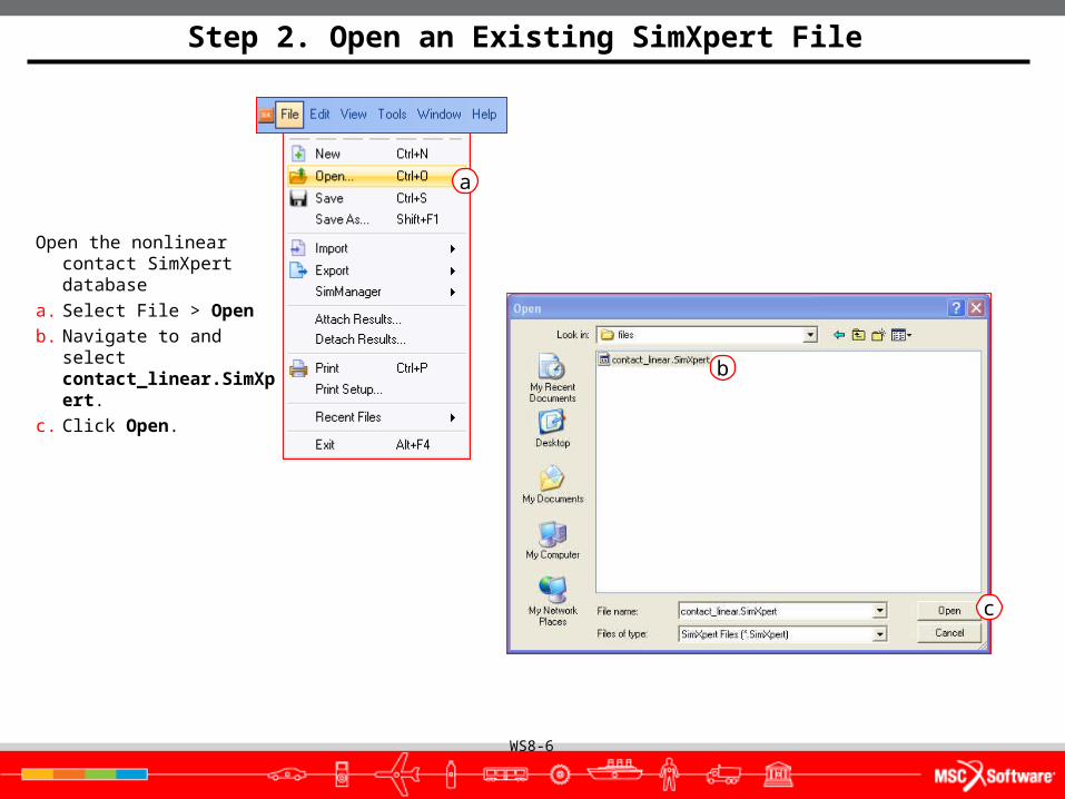
Step 2. Open an Existing SimXpert File
Open the nonlinear contact SimXpert database
a. Select File > Open
b. Navigate to and select contact_linear.SimXpert.
c. Click Open.
a
b
c

WS8-7
Step 3. Create a Contact Table
Define Glue option between the bolts
and plates and Touch option
between the plates.
a. Under the LBC’s tab, select Table from the Contact group
b. For Name enter Glue_Bolts
c. Click Glue All.
d. Click Deact. Diagonal to eliminate self-contact.
e. Since the bolts will not come into contact with each other, in row 1 (bolt_1) clear columns 2 and 3 by repeatedly clicking in each box until it is blank. In row 2 (bolt_2) clear column 3 by clicking in the box until it is blank.
f. In row 5 (top plate) change column 4 to ‘T’ by clicking in the box until it is changed.
g. Click OK.
a
dc
b
e
f
g

WS8-8
Step 4. Setup a Nonlinear Analysis
Specify analysis parameters.
a. Right-click the FileSet and select Create new Nastran Job.
b. Enter contact_nonlinear as the Job Name.
c. Select General Nonlinear Analysis (SOL400) for the Solution Type.
d. Click the folder icon to to the right of the Solver Input File text box.
e. Select the file path to where the Nastran job will be saved.
f. Enter contact_nonlinear in the File name textbox.
g. Click Save.
h. Click OK
a
b
c
d
e
f g
h
WS8-9
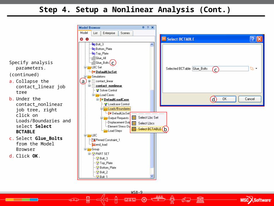
Step 4. Setup a Nonlinear Analysis (Cont.)
Specify analysis parameters.
(continued)
a. Collapse the contact_linear job tree
b. Under the contact_nonlinear job tree, right click on Loads/Boundaries and select Select BCTABLE
c. Select Glue_Bolts from the Model Browser
d. Click OK.
d
c
b
a
c

WS8-10
Step 4. Setup a Nonlinear Analysis (Cont.)
Specify analysis parameters.
(continued)
a. Right-click on Solver Control and select Properties.
b. Select ContactControlParameters
c. Check Activate Quadratic Contact
d. Click Apply.
e. Click Close.
ed
c
b
a
WS8-11
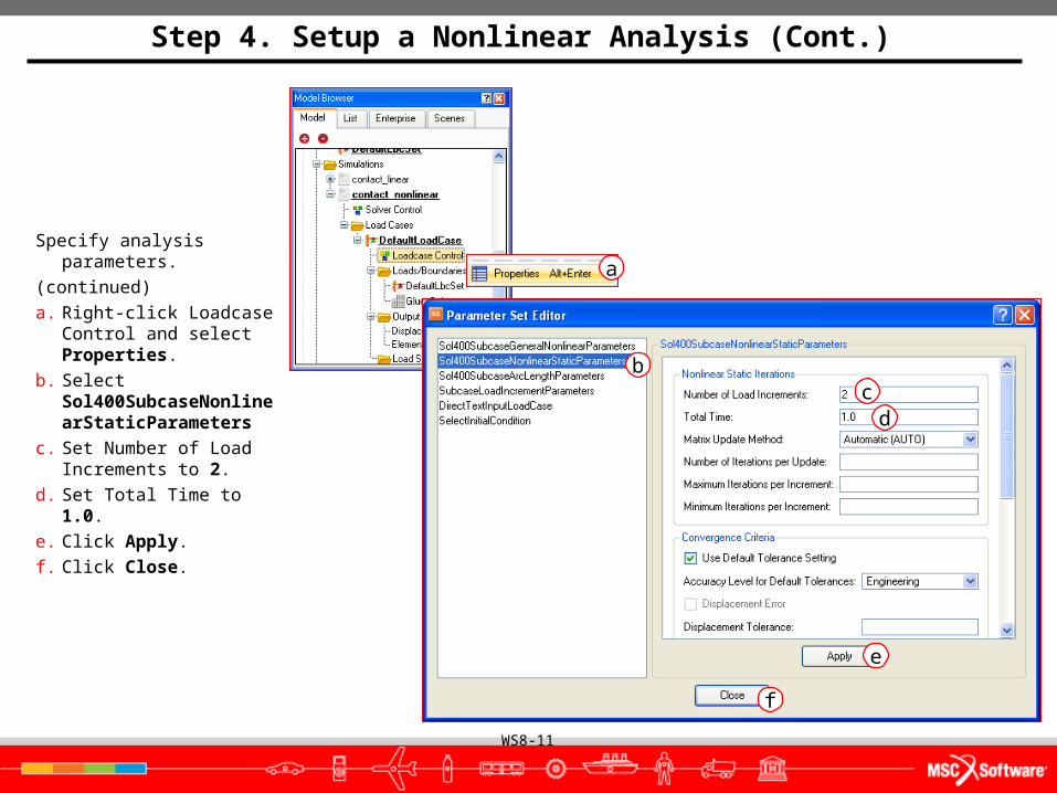
Step 4. Setup a Nonlinear Analysis (Cont.)
Specify analysis parameters.
(continued)
a. Right-click Loadcase Control and select Properties.
b. Select Sol400SubcaseNonlinearStaticParameters
c. Set Number of Load Increments to 2.
d. Set Total Time to 1.0.
e. Click Apply.
f. Click Close.
cd
e
f
b
a

WS8-12
Step 5. Run Analysis
Run Analysis
a. Right click on contact_nonlinear and select Run.
a

WS8-13
Step 6. Check the Progress
a. Open the f06 file using a text editor. If you cannot open the f06 because it is in use, create a copy of the file and open the copy.
b. Scroll to the end of the file.
c. If the job is still running you should see the iteration output table.
d. The LOAD STEP column indicates how much of the current load step it is attempting to solve. A value of 0.5 indicates that 50% of the load is being applied in this increment.
e. The number of iterations it has performed is shown in the ITR column.
f. When the job finishes, you will see a message confirming job convergence.
f
ed

WS8-14
Step 7. Attach the Results
Attach the .xdb file to access
the analysis results.
a. Select File > Attach Results.
b. Click the Folder icon for File Path.
c. Navigate to and select the file contact_nonlinear.xdb
d. Click Open.
e. Select Results as the Attach Option.
f. Click OK.
e
d
c
b
a
f

WS8-15
Step 8. Results - Deformation Plot
Deformation Plot.
a. Under the Results tab, select Deformation.
b. In Result cases select the contact_nonlinear.xdb job
c. Select Results Type Displacements, Translational.
d. Click the Deformation Tab
e. Select True for Deformed display scaling.
f. Click Update to show the true deformation.
f
b
c
d
a
e

WS8-16
Step 8. Results - Deformation Plot (Cont.)
Deformation Fringe Plot (Cont.)
a. Orient the model to Left View and zoom in to check separation between plates.
b. Change the value of True to 10 to see the separation exaggerated.
c. Click Update
d. Click Clear when finished. bc
d
a

WS8-17
Step 9. Results - Stress Fringe Plot
Generate a Stress Fringe Plot
a. Click the Plot Data tab
b. Select Fringe as the Plot type.
c. Select contact_nonlinear.xdb as the Result Case
d. Change Result type to Stress Tensor.
e. Select von Mises for Derivation:
f. Click Update.
g. Orient the model to Isometric view.
a
b
c
d e f
f
g
g

WS8-18
Step 10. Compare Linear and Nonlinear Results
Compare the nonlinear results with the linear results.
a. Select Window >New Window
b. Select Window > Tile
c. Click the frame of the Structures window to make it current
d. Select contact_linear.MASTER as the Result Case
e. Select Result type Stress Tensor.
f. Select von Mises for Derivation:
g. Click Update.
h. Click Clear and close the State plot property editor.
i. When you have finished viewing the results, click Clear
j. Close the Structures Window
a
b
c
ge
f h
i
j

WS8-19
Step 10. Compare Linear and Nonlinear Results (Cont.)
Compare the nonlinear results with the linear results. (Cont.)
a. Right-click Plot Fringe 01 in the Model Browser and select Delete
b. Answer Yes to the Delete Fringe 01? prompt.
a
b

WS8-20
Step 11. Save the Database
Save the database to continue later in the Nonlinear Material Workshop
a. Select File > Save As
b. Enter File Name contact_nonlinear
c. Click Save.
d. Select File > Exit
a
b c
d