Embed Size (px)
Citation preview
WRS Tunnel Disaster Response and Recovery Challenge Rule Book Ver.1.1.1
1/37
September 6, 2018
WRS Tunnel Disaster Response and
Recovery Challenge
Rule Book(Ver.1.1.1)
WRS Task Development Team
Competition Overview
1. Competition
1.1. Symbol, Type and Duration of Mission and Task
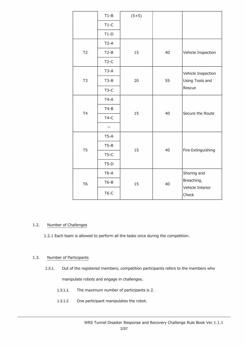
1.1.1. Mission and the duration for the tunnel disaster response challenge are as follows.
1.1.1.1. Duration is subject to change.
1.1.1.2. Even if there is a delay during the simulation, competition will not be allowed if the
actual time is exceeded.
(The challenge will end according to the actual time)
Figure 1-1: Task Symbol and Duration
Mission and Task Symbol Duration (Min/Mission)
Detail Mission Task
Simulation
World Time
(min)
Actual Time
(min)
T1 T1-A 10 25 Traversing Obstacles
WRS Tunnel Disaster Response and Recovery Challenge Rule Book Ver.1.1.1
2/37
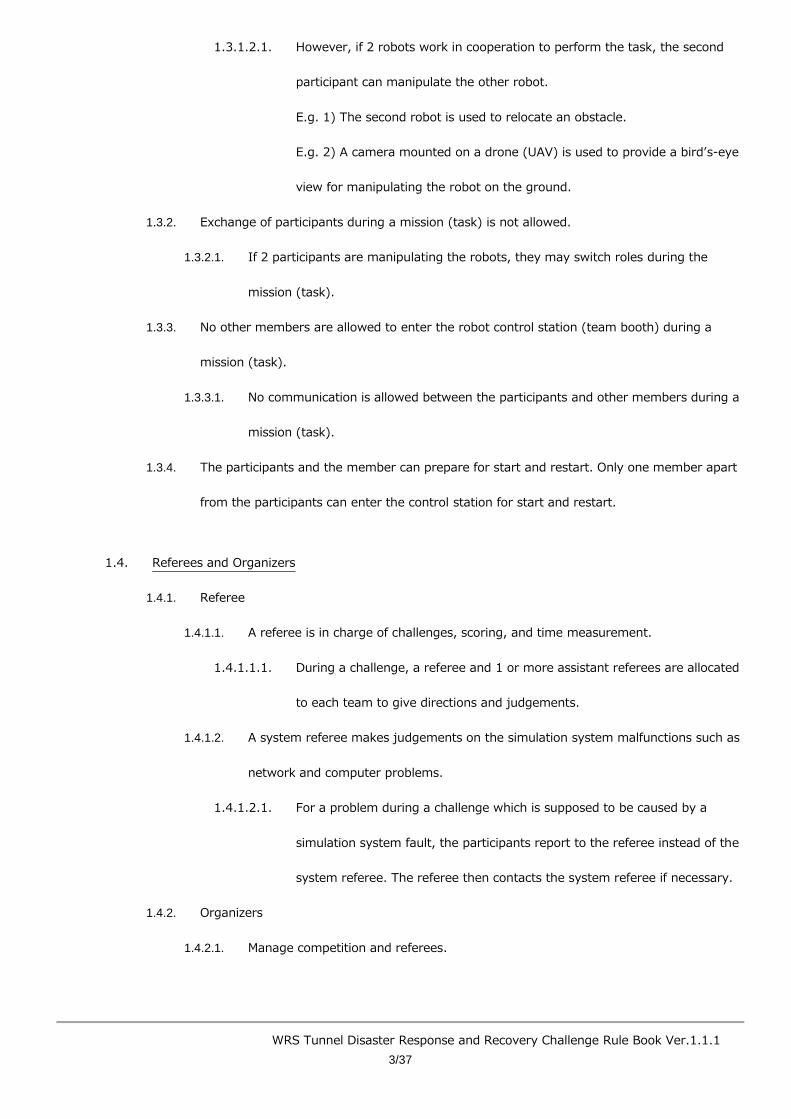
T1-B (5+5)
T1-C
T1-D
T2
T2-A
15 40 Vehicle Inspection T2-B
T2-C
T3
T3-A
20 55
Vehicle Inspection
Using Tools and
Rescue
T3-B
T3-C
T4
T4-A
15 40 Secure the Route T4-B
T4-C
ー
T5
T5-A
15 40 Fire Extinguishing T5-B
T5-C
T5-D
T6
T6-A
15 40
Shoring and
Breaching,
Vehicle Interior
Check
T6-B
T6-C
1.2. Number of Challenges
1.2.1 Each team is allowed to perform all the tasks once during the competition.
1.3. Number of Participants
1.3.1. Out of the registered members, competition participants refers to the members who
manipulate robots and engage in challenges.
1.3.1.1. The maximum number of participants is 2.
1.3.1.2. One participant manipulates the robot.
WRS Tunnel Disaster Response and Recovery Challenge Rule Book Ver.1.1.1
3/37
1.3.1.2.1. However, if 2 robots work in cooperation to perform the task, the second
participant can manipulate the other robot.
E.g. 1) The second robot is used to relocate an obstacle.
E.g. 2) A camera mounted on a drone (UAV) is used to provide a bird’s-eye
view for manipulating the robot on the ground.
1.3.2. Exchange of participants during a mission (task) is not allowed.
1.3.2.1. If 2 participants are manipulating the robots, they may switch roles during the
mission (task).
1.3.3. No other members are allowed to enter the robot control station (team booth) during a
mission (task).
1.3.3.1. No communication is allowed between the participants and other members during a
mission (task).
1.3.4. The participants and the member can prepare for start and restart. Only one member apart
from the participants can enter the control station for start and restart.
1.4. Referees and Organizers
1.4.1. Referee
1.4.1.1. A referee is in charge of challenges, scoring, and time measurement.
1.4.1.1.1. During a challenge, a referee and 1 or more assistant referees are allocated
to each team to give directions and judgements.
1.4.1.2. A system referee makes judgements on the simulation system malfunctions such as
network and computer problems.
1.4.1.2.1. For a problem during a challenge which is supposed to be caused by a
simulation system fault, the participants report to the referee instead of the
system referee. The referee then contacts the system referee if necessary.
1.4.2. Organizers
1.4.2.1. Manage competition and referees.
WRS Tunnel Disaster Response and Recovery Challenge Rule Book Ver.1.1.1
4/37
1.4.2.2. The chairperson of the organizers is required to be in charge of the competition.
WRS Tunnel Disaster Response and Recovery Challenge Rule Book Ver.1.1.1
5/37
2. Robots
2.1. Number of Robots
2.1.1. Up to 2 robots are allowed for all missions.
※ Refer to section 1.3 for details about who can manipulate the robots.
2.1.2. The same robots must be used throughout all missions.
2.2. Types of Robots
2.2.1. A platform robot or a self-built robot is used during the competition.
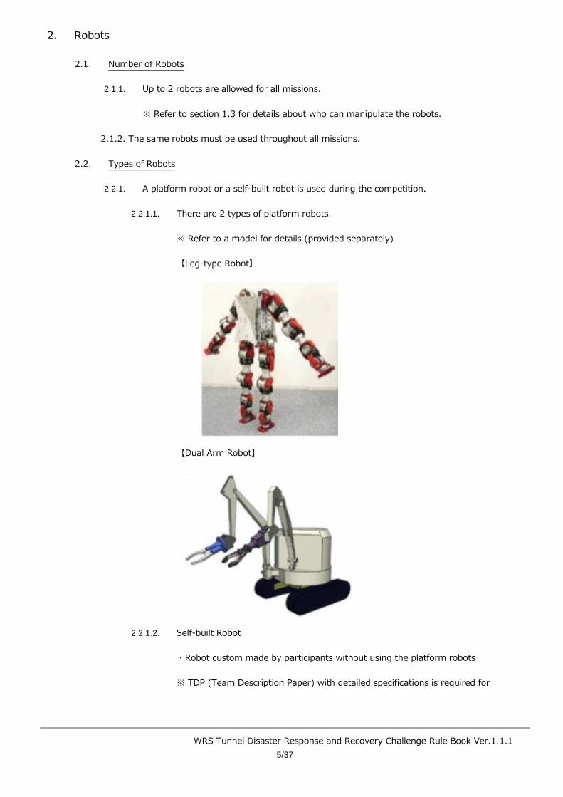
2.2.1.1. There are 2 types of platform robots.
※ Refer to a model for details (provided separately)
【Leg-type Robot】
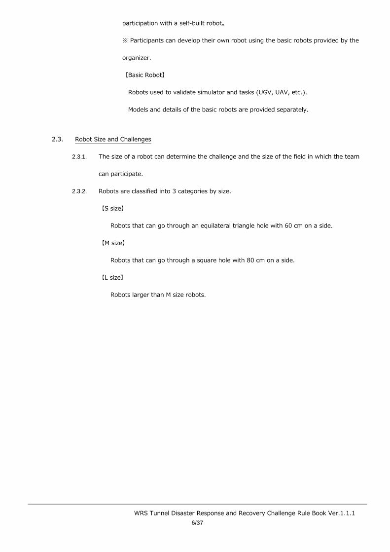
【Dual Arm Robot】
2.2.1.2. Self-built Robot
・Robot custom made by participants without using the platform robots
※ TDP (Team Description Paper) with detailed specifications is required for
WRS Tunnel Disaster Response and Recovery Challenge Rule Book Ver.1.1.1
6/37
participation with a self-built robot。
※ Participants can develop their own robot using the basic robots provided by the
organizer.
【Basic Robot】
Robots used to validate simulator and tasks (UGV, UAV, etc.).
Models and details of the basic robots are provided separately.
2.3. Robot Size and Challenges
2.3.1. The size of a robot can determine the challenge and the size of the field in which the team
can participate.
2.3.2. Robots are classified into 3 categories by size.
【S size】
Robots that can go through an equilateral triangle hole with 60 cm on a side.
【M size】
Robots that can go through a square hole with 80 cm on a side.
【L size】
Robots larger than M size robots.
WRS Tunnel Disaster Response and Recovery Challenge Rule Book Ver.1.1.1
7/37
3. Field
3.1. Field Placement
3.1.1. Inside the tunnel of two-way and two-lane road, each 3.6 m wide with 1 m frontage roads
on both sides.
3.1.2. The distance between the start and goal varies according to the tasks, which are to be
completed inside the tunnel.
3.2. Direction and Coordinates
3.2.1. The center of a start line is the coordinate origin.
3.2.2. The coordinate system is a right-handed system with (+) X coordinate toward a red pole
and (+) Z coordinate upward from the origin.
3.2.3. (+) direction of Y coordinate is called forward and (-) backward.

WRS Tunnel Disaster Response and Recovery Challenge Rule Book Ver.1.1.1
8/37
4. Start and Goal
4.1. Mission and Start
4.1.1. Basically, a challenge starts at every mission or task.
4.2. Gate and Line
4.2.1. A gate with red and blue poles is placed at a start point, goal, and checkpoints.
4.2.2. Each gate is equipped with numbered flags starting from “1”, which is referred to as a gate
number.
4.2.3. The line that connects both sides of the gates is called a gate line (As with a gate number,
referred to as gate line No. 1).
4.2.3.1. A gate line at a start point for each mission (or task) is called a start line.
4.2.3.2. A gate line at a checkpoint for each mission (or task) is called a checkpoint line.
4.2.3.3. A gate line at a goal for each mission (or task) is called a goal line.
4.2.3.4. A robot has to start from a start point and aim at the gate of the goal by passing the
gate lines as checkpoints in the numerical order.
4.2.3.5. A robot has to go through gates with a red pole on the right.
4.3. Duration
4.3.1. The duration of the challenge is described in Table 1-1.
4.3.1.1. Competing will not be allowed if the actual time is exceeded.
4.3.2. Preparation time is included in the time slot (including preparation for a restart).
4.4. Starting
4.4.1. A start point is anywhere behind the start line.
4.4.1.1. A robot is not allowed to take an active action before the start.
4.4.1.1.1. Using sensors, etc. to acquire information about the field beyond the start
line prior to starting is prohibited.
4.4.2. No part of a robot can be in front of the start line, including the space above.
WRS Tunnel Disaster Response and Recovery Challenge Rule Book Ver.1.1.1
9/37
4.4.3. The procedure for a start is as follows.
4.4.3.1. Participants set up necessary equipment for robot operation on the table in the
control station.
4.4.3.2. With the referee’s call to start, the mission starts along with the preparation.
4.4.3.2.1. Preparation includes a network connection between the robot operation
computer and the competition system.
4.4.4. Time starts with the announcement of a start.
4.5. Goals
4.5.1. When a referee confirms a robot marker passes a goal line, the mission is ended.
4.5.1.1. If 2 robots are used, the robot marker of both robots must pass the goal line and be
confirmed by the referee to count as a goal.
4.5.2. The robot marker, which is placed at an easily recognizable point of the robot for a referee,
is the position of a sphere attached to the robot.
4.5.2.1. The sphere must be presented with the field model.
4.5.3. When the goal is reached, the mission (task) ends and the timer stops.
4.5.3.1. If 2 robots are used, the goal must be reached by both before the mission (task)
ends and the timer stops.
4.5.4. A robot can reach the goal without completing all the tasks required in each task (subtask),
such as target identification.
4.5.4.1. In this case, there are no point elements for unattempted tasks.
4.5.4.2. Additional point elements (time) will not be added.
※ Refer to 6.3.5 for information regarding additional point elements (time).
4.6. Checkpoints
4.6.1. Checkpoints are placed between the start and the goal.
4.6.2. A referee has to ensure that a robot marker passes the checkpoint line.
4.6.2.1. If 2 robots are used, both robots must pass the checkpoint.

WRS Tunnel Disaster Response and Recovery Challenge Rule Book Ver.1.1.1
10/37
4.7. Restarting
4.7.1. Participants can request a restart.
4.7.1.1. Restarting is starting again after the initial start.
4.7.1.2. Restarts must comply with the starting procedure.
4.7.1.2.1. In case of restart, the field conditions return to the initial state.
4.7.2. Preparation for the restart begins with the referee accepts the restart request.
4.7.2.1. The restart cannot be withdrawn once the referee accepts it.
4.7.2.2. There is no need to restart if abstention is requested after a restart is accepted.
4.7.3. Participants can request a restart for their own convenience.
4.7.3.1. In case of restart, the restart line is any line set by the system (start line,
checkpoint line) behind the position where the restart is requested.
4.7.3.1.1. The position of the lines will vary by mission.
4.7.3.2. Scoring elements and penalties that occur behind the restart line remain valid.
4.7.3.3. Scoring elements and penalties that occur in front of the restart line are withdrawn.
4.7.4. When a restart is accepted, time stops and the field returns to the initial state. The restart
beings with the referee’s announcement, and time starts again.
4.7.5. The duration of the mission after the restart is the time remaining after subtracting the time
when the referee accepted the restart from the of the official mission duration.
E.g.) If a restart is accepted at 4 minutes 30 seconds in with a 10 minute mission time,
the remaining time after the restart is 5 minutes 30 seconds.
4.7.6. There is no limit to the number of restarts.
4.7.7. When a referee decides the participants need a restart, the restart is mandatory. This
restart is called a forced restart.
4.8. Abstention
4.8.1. Participants may abstain from all or part of a mission (task).
WRS Tunnel Disaster Response and Recovery Challenge Rule Book Ver.1.1.1
11/37
4.8.1.1. Participants must request a referee for the abstention.
4.8.2. In case of abstention during a challenge, points are given only when a robot passes through
a checkpoint line.
E.g.) When Task A and B are executed consecutively, points earned in task A are
valid regardless of abstention during task B after the completion of task A.

WRS Tunnel Disaster Response and Recovery Challenge Rule Book Ver.1.1.1
12/37
5. Targest
5.1. Definition of a Target
5.1.1. Targets consist of QR codes and pipes. The size of a QR code and the length of a pipe as a
target is described in the following table.
Table: 5-1 Type and symbol of target
Target Symbol
Width of QR code (mm)
140 35 7
Length of Pipe
(mm)
0 140-0 35-0 7-0
50 140-50 35-50 7-50
100 140-100 35-100 7-100
5.1.2. QR codes used as a target are version 1 (number of cells: 21 x 21). Q (25 %) is used as the
error correction level.
Figure 5-1-1: Target (140-50)
5.2. Target for Vehicle (Interior/Exterior), Road Surface, and Tunnel Structure
5.2.1. Use targets as specified in 5.1.1.
5.3. Target for Victim Identification
5.3.1. QR codes are attached to the face, arms, and legs of dummy victims.

WRS Tunnel Disaster Response and Recovery Challenge Rule Book Ver.1.1.1
13/37
5.3.1.1. This is called the dummy target.
5.3.2. The size and specification of QR codes are the same as for vehicles.
Figure: 5-3-1 Dummy and Dummy Target
(QR code attached to the face)
5.4. Number of Targets
5.4.1. The number of targets varies according to each mission.
5.5. Identification of Targets
5.5.1. Target identification is reading a QR code on a target.
5.5.1.1. Participants are to report finding QR codes to referees.
5.6. Position and Location of Targets
5.6.1. The height of the target will be between 0 mm and 2400 mm.
5.6.2. A target’s position is the coordinate center (x, y, z) of a target.
5.6.3. A target’s location is the approximate location of a target in the field, which is represented
as a symbol.
5.6.3.1. The symbol is defined separately.
WRS Tunnel Disaster Response and Recovery Challenge Rule Book Ver.1.1.1
14/37
5.6.4. The following positions are used when the target is a victim.
H: Head, B: Torso, L: Legs, A: Arms
5.7. Reporting Targets
5.7.1. Participants are to report a target’s position for tasks which require the report.
5.7.1.1. CSV format will be used (including QR codes and x, y, z coordinates).
5.7.1.2. The dummy target information will be in CSV format (including QR codes and
location of the target).
5.7.1.2.1. The coordinate unit will be millimeters. The unit itself will not be displayed.
5.7.1.2.2. The following format will be used.
・When the position of the target is read:
Each piece of information about the target will appear on a separate
line and be delimited by commas.
(E.g.)
QR code, x, y, z
QR code, x, y, z
QR code, x, y, z
・ For the dummy target:
Each piece of information about the dummy target will appear on one
line
(E.g.)
In the case of the head QR code:
Q code, Head
5.7.2. The following describes the file-naming conventions. A file will be created for each task.
・TeamCode_Task_CompetitionDate.csv
# The team code will be the number prepared by the office.
WRS Tunnel Disaster Response and Recovery Challenge Rule Book Ver.1.1.1
15/37
# The competition date will be in Month-Day format.
E.g.) Where team Z3 performed task T2-B on October 17:
Z3_T2-B_10-17.csv
5.7.2.1. The code for line breaks will be Linux (LF).
5.7.3. The target report will be complete when the file is saved to the specified location.
5.7.4. The target report should be performed quickly after completing the challenge.
6. Rankings, Scoring, Penalties, and Disqualification
6.1. Rankings
6.1.1. Award placement is determined by the ranking of cumulative scores.
6.2. Scoring
6.2.1. Perform scoring elements in each mission (task) to earn points and meet the requirements
for additional point elements to earn the additional points.
6.2.2. The official record is the point rounded off to the first decimal place.
6.3. Scoring Elements and Additional Point Elements
6.3.1. Scoring elements are the tasks for earning points allocated to each mission.
6.3.1.1. Perform scoring elements to earn points.
6.3.2. Additional points can be scored depending on the conditions specified in each mission such
as obstacles.
6.3.2.1. Additional points are valid only when scoring points are earned.
6.3.2.2. Additional points for tasks will be multiplied by a factor of 0.1 to 1.0 depending on
the point element.
6.3.2.2.1. This is called the additional point factor.
6.3.3. Additional point elements (environmental) are awarded when environmental information
from the field (map, temperature, etc.) is submitted.
6.3.3.1. 3-dimensional environmental information such as maps or temperatures must be
submitted in the standard point-cloud format.
WRS Tunnel Disaster Response and Recovery Challenge Rule Book Ver.1.1.1
16/37
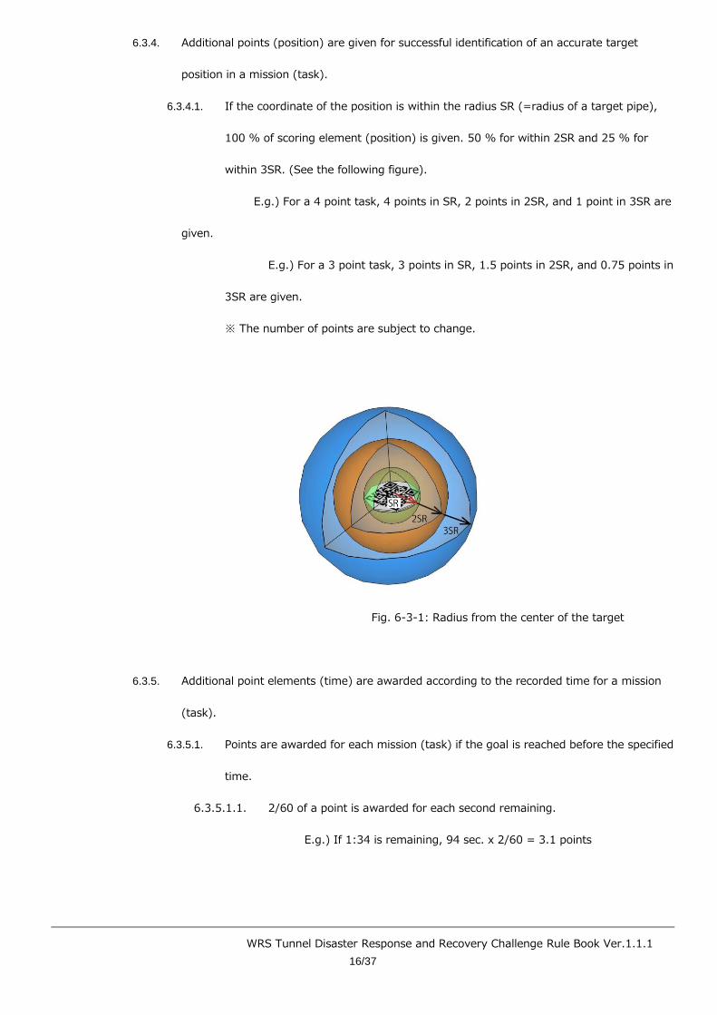
6.3.4. Additional points (position) are given for successful identification of an accurate target
position in a mission (task).
6.3.4.1. If the coordinate of the position is within the radius SR (=radius of a target pipe),
100 % of scoring element (position) is given. 50 % for within 2SR and 25 % for
within 3SR. (See the following figure).
E.g.) For a 4 point task, 4 points in SR, 2 points in 2SR, and 1 point in 3SR are
given.
E.g.) For a 3 point task, 3 points in SR, 1.5 points in 2SR, and 0.75 points in
3SR are given.
※ The number of points are subject to change.
Fig. 6-3-1: Radius from the center of the target
6.3.5. Additional point elements (time) are awarded according to the recorded time for a mission
(task).
6.3.5.1. Points are awarded for each mission (task) if the goal is reached before the specified
time.
6.3.5.1.1. 2/60 of a point is awarded for each second remaining.
E.g.) If 1:34 is remaining, 94 sec. x 2/60 = 3.1 points
WRS Tunnel Disaster Response and Recovery Challenge Rule Book Ver.1.1.1
17/37
■ The amount of points awarded for the additional point element
(time) may change.
6.3.5.2. If a tool is used, and the tool is not brought to the goal, the above points will not be
awarded.
6.3.6. Point Deductions
6.3.6.1. If the mission (task) specifies a reduced point element, performing the action for
that element will lead to point deduction.
6.3.6.1.1. A referee may impose point deductions in addition to those specified as
determined appropriate.
■ The point deduction will be evaluated by the referees and the
challenge committee, and the chair of the challenge committee will
make the final decision.
6.3.6.1.2. Actions that lead to point deductions as well as the amount of the
deductions will be publicized.
6.4. Disqualification, Cheating
6.4.1. Conditions for disqualification
6.4.1.1. Fragrant cheating is discovered by a referee, etc.
6.4.1.2. The cheating involves the implementation of the challenge, a robot, tools, etc.
6.4.1.3. Instructions of a referee or challenge committee member are not followed during or
leading up to competition.
6.4.1.4. In the case of disqualification, an explanation will be provided to an individual
representative from each team, opinions will be gathered, and after deliberation
among the referees and challenge committee members, the chair of the challenge
committee will make the final decision.
6.4.2. Consequences of Disqualification
WRS Tunnel Disaster Response and Recovery Challenge Rule Book Ver.1.1.1
18/37
6.4.2.1. The challenge will be ended and participation in subsequent challenges will not be
allowed.
6.4.2.2. All points will be deducted and the disqualification will be publicly recorded.
6.4.3. Cheating
6.4.3.1. If fragrant cheating is discovered by a referee, etc., the challenge will be ended.
6.4.3.1.1. If the challenge is ended, all points acquired in that challenge will be
deducted.
6.4.3.1.2. In this case, an explanation will be provided to an individual representative
from each team, opinions will be gathered, and after deliberation among the
referees and challenge committee members, the chair of the challenge
committee will decide the response. If the cause of the compulsory ending
to the challenge is resolved, the challenge will be allowed to be repeated,
and participation in subsequent challenges will also be allowed.

WRS Tunnel Disaster Response and Recovery Challenge Rule Book Ver.1.1.1
19/37
Mission T: Tunnel Disaster Response and Recovery Challenge
7. Mission
7.1. Common Items in the Mission
7.1.1. Tasks in each mission refer to basic technology of a robot required to complete a mission.
7.1.2. Information including field maps cannot be obtained prior to the start, because it simulates a
disaster mission.
7.1.2.1. Field environments and conditions can be changed even in the same mission
depending on the location of a robot and the mission time.
7.1.3. Field environments and conditions include the following parameters
● Lighting
● Wind
● Condition of wireless communication
● Temperature
● Visibility
● Field configuration
● Other limiting factors for robot mobility
7.2. Using Tools
7.2.1.1. Robots must execute tasks with functions already equipped by the robot.
7.2.1.1.1. Robots can use tools in the field prepared in advance by the organizers.
7.2.1.2. Robots can use simple tools depending on a mission (task). Simple tools refers to
tools without advanced mechanisms, E.g., a platform table and a long stick with a
camera mounted on the edge (also known as a camera stick, etc.).
7.2.1.3. When using simple tools, robots must hold the simple tools at the start of a mission
and carry them until the goal is reached.
WRS Tunnel Disaster Response and Recovery Challenge Rule Book Ver.1.1.1
20/37
7.3. Mission【T1】: Traversing Obstacles
7.3.1. Outline
7.3.1.1. Traverse and negotiate the following obstacles individually or in combination.
7.3.1.1.1. The size of a robot determines which tasks are to be executed.
■ Task 【T1-A】: Crossing Ramps
For S- and M-sized robots
■ Task 【T1-B】: Elevated Ramps
For S- and M-sized robots
■ Task 【T1-C】: Narrow Space
For robots of all sizes
■ Task 【T1-D】: Uneven Terrain (Chocolate & Waffle)
For L-sized robots
7.3.1.1.2. S- and M-sized robots must perform the two tasks specified from among
【T1-A】,【T1-B】, and【T1-C】.
L-sized robots must perform【T1-C】 and【T1-D】.
7.3.2. Obstacle Details (Type and Shape)
7.3.2.1. 【T1-A】:Crossing Ramps【S- and M-sized robots】
Alternating hill terrain with a 15 degree slope.
7.3.2.2. 【T1-B】:Elevated Ramps【S- and M-sized robots】
Diagonal hill terrain with 15-degree ramps of varied height.
7.3.2.3. 【T1-C】:Confined Space (Jungle Gym)【Robots of all sizes】
7.3.2.3.1. Traverse in continuously linked rectangular frames. (Refer to figures 7-3-1
and 7-3-2)

WRS Tunnel Disaster Response and Recovery Challenge Rule Book Ver.1.1.1
21/37
7.3.2.3.2. Obstacles types, shapes, and symbols
【Symbols】
Type (J) – Standard width (U) – Magnification Factor (S) – Height (h)
Type: J
Standard Width (U): Width of a basic rectangular frame. The unit is meters.
Magnification Factor (S): Magnification factor of a frame. Ratio (%) to a
frame of standard width.
Height (h): Height of a frame. Ratio to the width of the frame width w (= U
x S)
E.g.)J-1-100-1
A frame with W = 1 m on one side and W = 1 m height
E.g.)J-1-70-1.5
A frame with W = 70 cm on one side and with W = 1.05 m height.
Figure 7-3-1: Frame
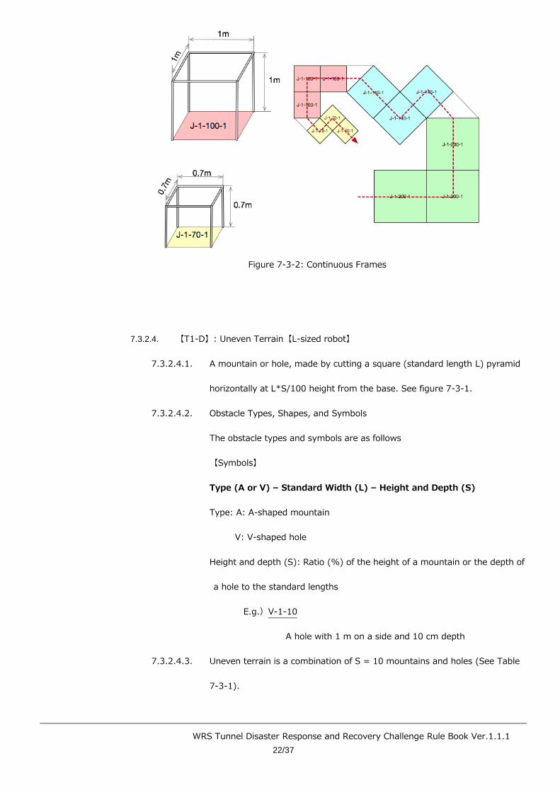
WRS Tunnel Disaster Response and Recovery Challenge Rule Book Ver.1.1.1
22/37
Figure 7-3-2: Continuous Frames
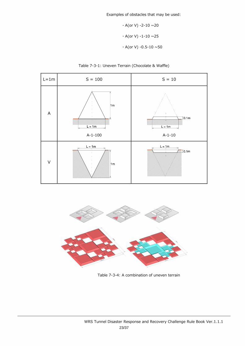
7.3.2.4. 【T1-D】: Uneven Terrain【L-sized robot】
7.3.2.4.1. A mountain or hole, made by cutting a square (standard length L) pyramid
horizontally at L*S/100 height from the base. See figure 7-3-1.
7.3.2.4.2. Obstacle Types, Shapes, and Symbols
The obstacle types and symbols are as follows
【Symbols】
Type (A or V) – Standard Width (L) – Height and Depth (S)
Type: A: A-shaped mountain
V: V-shaped hole
Height and depth (S): Ratio (%) of the height of a mountain or the depth of
a hole to the standard lengths
E.g.)V-1-10
A hole with 1 m on a side and 10 cm depth
7.3.2.4.3. Uneven terrain is a combination of S = 10 mountains and holes (See Table
7-3-1).
WRS Tunnel Disaster Response and Recovery Challenge Rule Book Ver.1.1.1
23/37
Examples of obstacles that may be used:
・A(or V) -2-10 ~20
・A(or V) -1-10 ~25
・A(or V) -0.5-10 ~50
Table 7-3-1: Uneven Terrain (Chocolate & Waffle)
L=1m S = 100 S = 10
A
A-1-100
A-1-10
V
Table 7-3-4: A combination of uneven terrain

WRS Tunnel Disaster Response and Recovery Challenge Rule Book Ver.1.1.1
24/37
7.3.3. Scoring / Losing Points
7.3.3.1. Point elements
・Passing a checkpoint: 8 pts. x 3 locations
・Passing the goal: 8 pts.
7.3.3.2. Additional point elements (Time: all checkpoints must be passed)
・Refer to section 6.3.5.
7.3.3.3. Additional point elements (Tasks)
・Maximum additional point factor of 0.5.
7.3.3.4. Reduced point elements
・None.
7.4. Mission【T2】: Vehicle Inspection
7.4.1. Outline
Investigate the inside and outside of a vehicle and its surroundings.
Investigation is to identify a target on the specified spot and report its findings.
7.4.1.1. Execute the following 3 tasks.
7.4.1.1.1. 【T2-A】Search victims and report their conditions.
Open the door, identify targets and dummy targets inside, and report.
7.4.1.1.2. 【T2-B】Investigate the vehicle conditions.
Identify targets placed outside of a vehicle, and report.
7.4.1.1.3. 【T2-C】Investigate the surroundings of a vehicle (tunnel roof, wall, and
road surface).
Identify targets placed around a vehicle (road surface), and report.
7.4.2. Scoring / Losing Points
WRS Tunnel Disaster Response and Recovery Challenge Rule Book Ver.1.1.1
25/37
7.4.2.1. Point Elements
【T2-A】
・Opening a door: 6 pts.
・Acknowledging a target: 4 pts., 1 location
・Acknowleding the dummy target: 4 pts., 1 location
【T2-B】
・Acknowledging the target: 2 pts., 2 locations
【T2-C】
・Acknowledging the target: 2 pts., 2 locations
7.4.2.2. Additional point elements (Position)
・Refer to 6.3.4.
7.4.2.3. Additional point elements (Time:【T2-A】, 【T2-B】, and【T2-C】 must all be
performed)
・Refer to section 6.3.5.
7.4.2.4. Additional point elements (Environmental)
・According to the quality of the information gathered in【T2-A】, a
maximum of 5 pts.
・According to the quality of the information gathered in 【T2-B】 and
【T2-C】 (vehicle periphery), a maximum of 5 pts.
7.4.2.5. Reduced point elements
・None.
7.5. Mission【T3】: Vehicle Inspection Using Tools and Victim Extraction
7.5.1. Outline
Open or remove a door using specified tools to rescue victims left in a vehicle.
A 15 kg spreader is to be used as the tool.

WRS Tunnel Disaster Response and Recovery Challenge Rule Book Ver.1.1.1
26/37
7.5.1.1. Execute tasks using the following procedures.
(1) 【T3-A】Grasp the tool (spreader).
○ Grasp the tool, move, and use the tool on the door to complete the task.
(2) 【T3-B】Execute one of the following to rescue victims inside a vehicle.
(A) Cut the lock side of a door top open it.
(B) Cut both the lock and hinged sides of a door (3 places total) to open and
remove the door.
The following conditions are applied when executing above tasks (A) and (B).
○ Cutting position is indicated as a yellow triangle.
○ The door weights 18 kg.
○ Hold for 10 seconds while pushing the head of the spreader vertically with
150 N of force against the cutting position. Reaction force resulting from the
door breakage will be transmitted to the robot through the spreader.
○ When the spreader head is placed in the right position and direction, the
yellow indicator will appear adjacent to the spreader and turn into red in 3
seconds.
○ Errors in coordinate position and direction are allowed up to ±30 mm and
±5° respectively.
(3) 【T3-C】Identify dummy targets in a vehicle, rescue the victims inside, and transfer
them to a designated area.
○ The dummy target is 165 cm tall and weighs 65 kg.
7.5.2. Scoring / Losing Points
7.5.2.1. Point Elements
【T3-A】
・Grasp the spreader: 6 pts.

WRS Tunnel Disaster Response and Recovery Challenge Rule Book Ver.1.1.1
27/37
【T3-B】
・Remove the door: 10 pts.
【T3-C】
・Help the victim: 14 pts.
7.5.2.2. Additional point elements (Time:【T3-A】, 【T3-B】, and【T3-C】 must all be
performed)
・ Refer to section 6.3.5.
7.5.2.3. Additional point elements (Environmental)
・According to the quality of the information gathered in 【T3-C】, a
maximum of 5 pts.
7.5.3. Reduced point elements
・None.
7.6. Mission【T4】: Securing a Route
7.6.1. Outline
・Perform the following tasks on the obstacles. These tasks are called “obstacle removal”.
(1) Transfer the obstacle outside of the path.
(2) Stack the obstacle in the designated location outside of the path.
(3) Remove the obstacle and transfer it outside of the path.
・The shape, size, and weight of obstacles differs according to the task. Obstacles are either
placed individually, in combination, or in stacks.
・The basic shape of the obstacles is an L or a J and the shape varies by task.
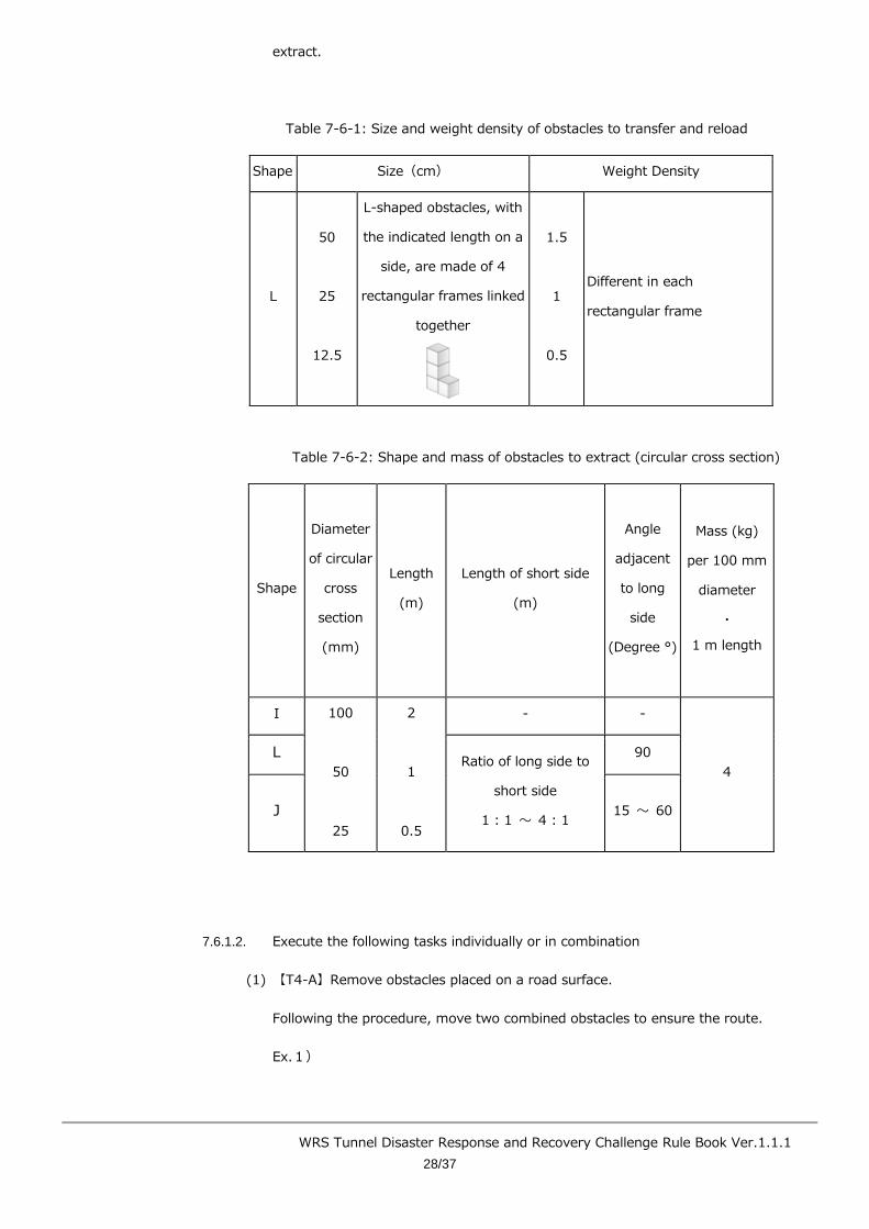
7.6.1.1. Obstacle Shape and Weight
Table 7-6-1 shows the size and specific weight of the L-shaped obstacles to
transfer and reload. Table 7-6-2 shows the shape and mass of the obstacles to
WRS Tunnel Disaster Response and Recovery Challenge Rule Book Ver.1.1.1
28/37
extract.
Table 7-6-1: Size and weight density of obstacles to transfer and reload
Shape Size(cm) Weight Density
L
50
25
12.5
L-shaped obstacles, with
the indicated length on a
side, are made of 4
rectangular frames linked
together
1.5
1
0.5
Different in each
rectangular frame
Table 7-6-2: Shape and mass of obstacles to extract (circular cross section)
Shape
Diameter
of circular
cross
section
(mm)
Length
(m)
Length of short side
(m)
Angle
adjacent
to long
side
(Degree °)
Mass (kg)
per 100 mm
diameter
・
1 m length
I 100
50
25
2
1
0.5
- -
4
L Ratio of long side to
short side
1 : 1 〜 4 : 1
90
J 15 〜 60
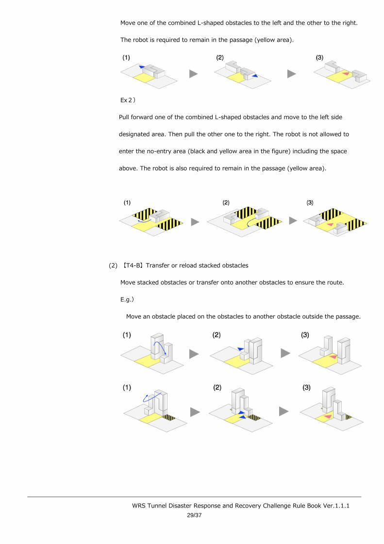
7.6.1.2. Execute the following tasks individually or in combination
(1) 【T4-A】Remove obstacles placed on a road surface.
Following the procedure, move two combined obstacles to ensure the route.
Ex.1)
WRS Tunnel Disaster Response and Recovery Challenge Rule Book Ver.1.1.1
29/37
Move one of the combined L-shaped obstacles to the left and the other to the right.
The robot is required to remain in the passage (yellow area).
Ex2)
Pull forward one of the combined L-shaped obstacles and move to the left side
designated area. Then pull the other one to the right. The robot is not allowed to
enter the no-entry area (black and yellow area in the figure) including the space
above. The robot is also required to remain in the passage (yellow area).
(2) 【T4-B】Transfer or reload stacked obstacles
Move stacked obstacles or transfer onto another obstacles to ensure the route.
E.g.)
Move an obstacle placed on the obstacles to another obstacle outside the passage.
WRS Tunnel Disaster Response and Recovery Challenge Rule Book Ver.1.1.1
30/37
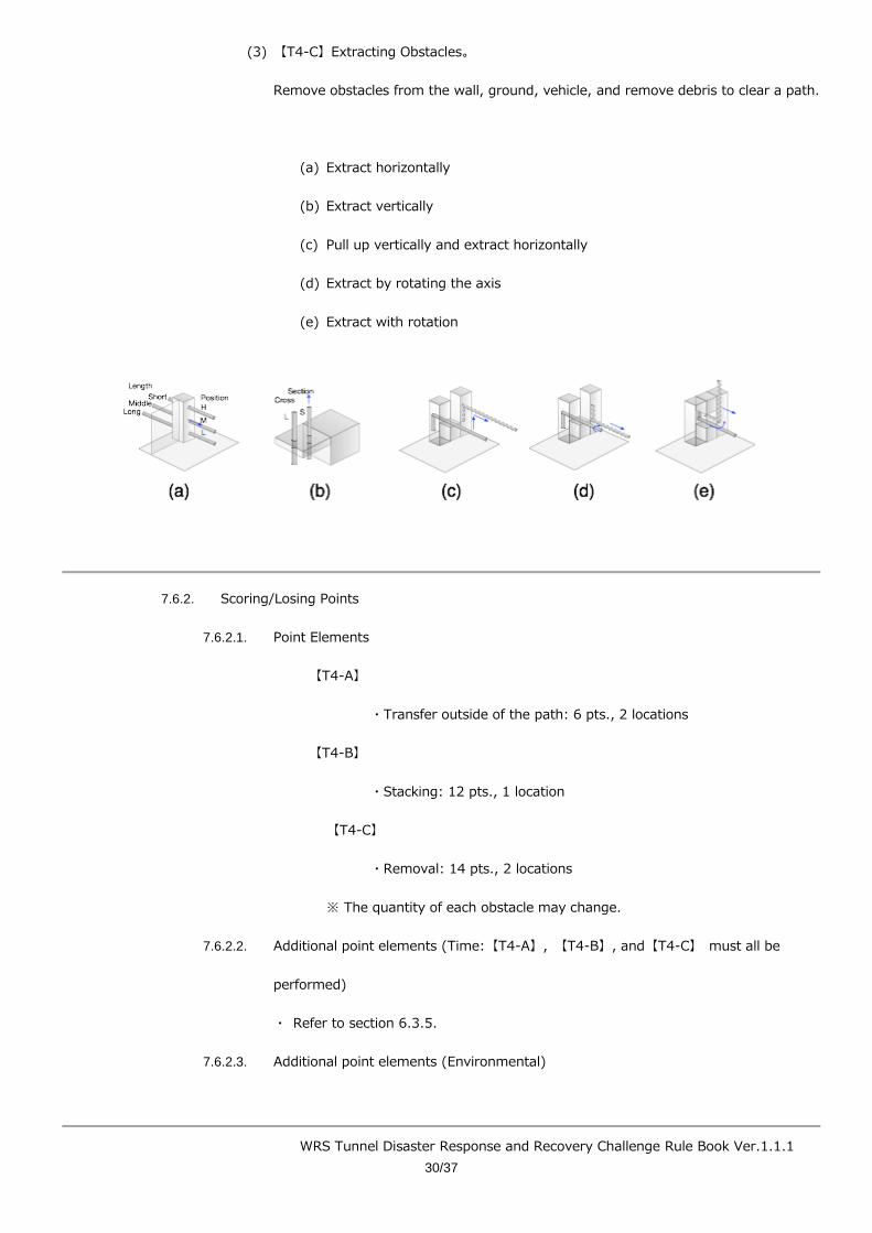
(3) 【T4-C】Extracting Obstacles。
Remove obstacles from the wall, ground, vehicle, and remove debris to clear a path.
(a) Extract horizontally
(b) Extract vertically
(c) Pull up vertically and extract horizontally
(d) Extract by rotating the axis
(e) Extract with rotation
7.6.2. Scoring/Losing Points
7.6.2.1. Point Elements
【T4-A】
・Transfer outside of the path: 6 pts., 2 locations
【T4-B】
・Stacking: 12 pts., 1 location
【T4-C】
・Removal: 14 pts., 2 locations
※ The quantity of each obstacle may change.
7.6.2.2. Additional point elements (Time:【T4-A】, 【T4-B】, and【T4-C】 must all be
performed)
・ Refer to section 6.3.5.
7.6.2.3. Additional point elements (Environmental)
WRS Tunnel Disaster Response and Recovery Challenge Rule Book Ver.1.1.1
31/37
・According to the quality of the information gathered throughout the field,
a maximum of 5 pts.
7.6.2.4. Additional point elements (Tasks)
・Maximum additional point factor of 1.0.
7.6.2.5. Reduced point elements
・None.
7.7. Mission【T5】: Fire Extinguishing
7.7.1. Outline
Extinguish a fire in a tunnel with firefighting equipment installed in a tunnel.
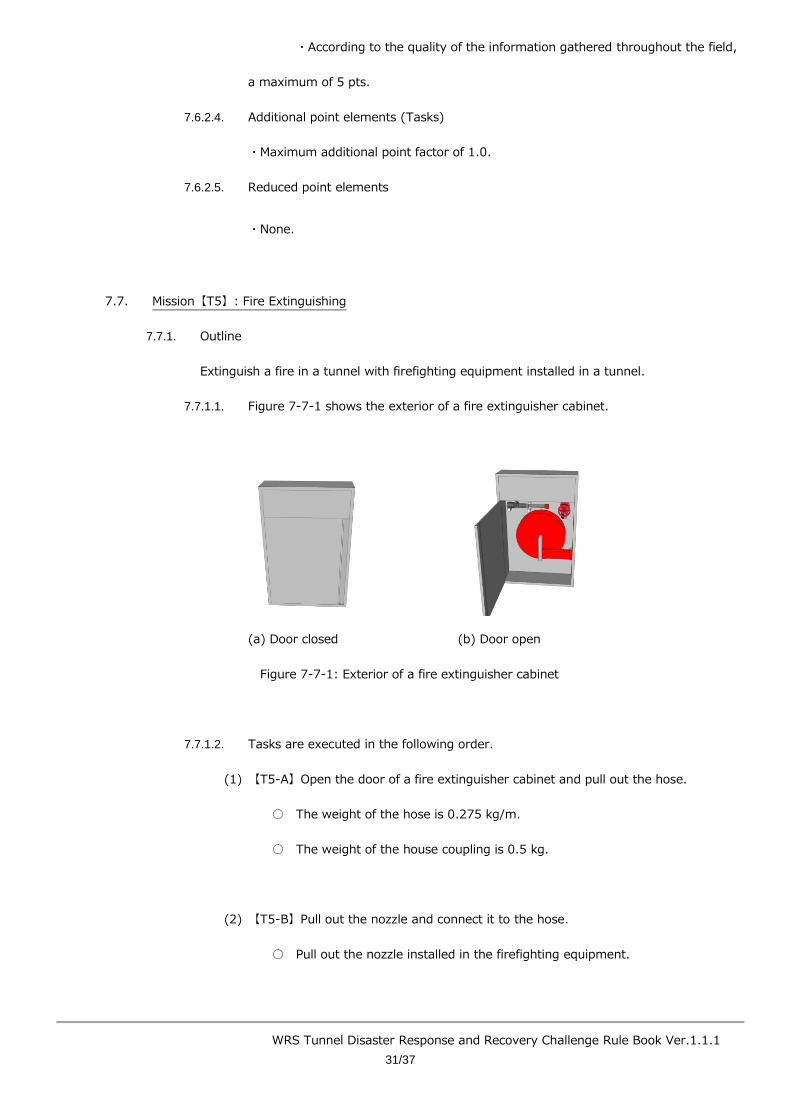
7.7.1.1. Figure 7-7-1 shows the exterior of a fire extinguisher cabinet.
(a) Door closed (b) Door open
Figure 7-7-1: Exterior of a fire extinguisher cabinet
7.7.1.2. Tasks are executed in the following order.
(1) 【T5-A】Open the door of a fire extinguisher cabinet and pull out the hose.
○ The weight of the hose is 0.275 kg/m.
○ The weight of the house coupling is 0.5 kg.
(2) 【T5-B】Pull out the nozzle and connect it to the hose.
○ Pull out the nozzle installed in the firefighting equipment.
WRS Tunnel Disaster Response and Recovery Challenge Rule Book Ver.1.1.1
32/37
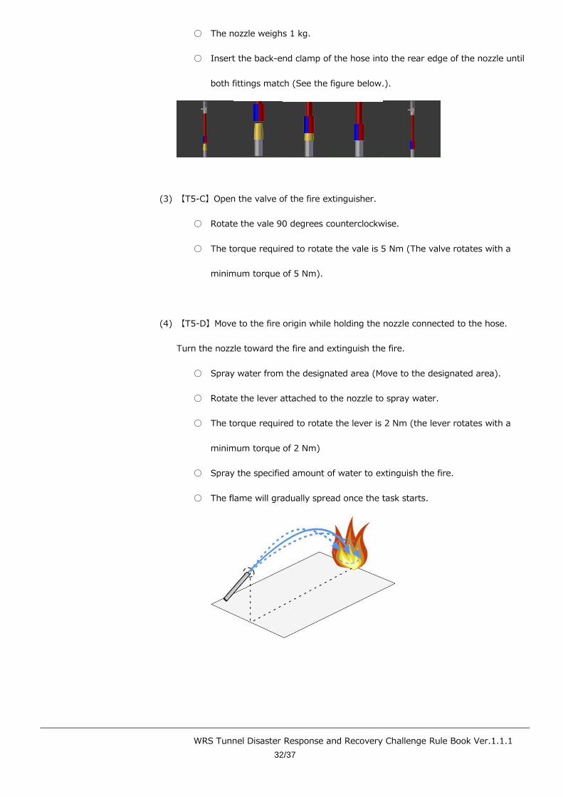
○ The nozzle weighs 1 kg.
○ Insert the back-end clamp of the hose into the rear edge of the nozzle until
both fittings match (See the figure below.).
(3) 【T5-C】Open the valve of the fire extinguisher.
○ Rotate the vale 90 degrees counterclockwise.
○ The torque required to rotate the vale is 5 Nm (The valve rotates with a
minimum torque of 5 Nm).
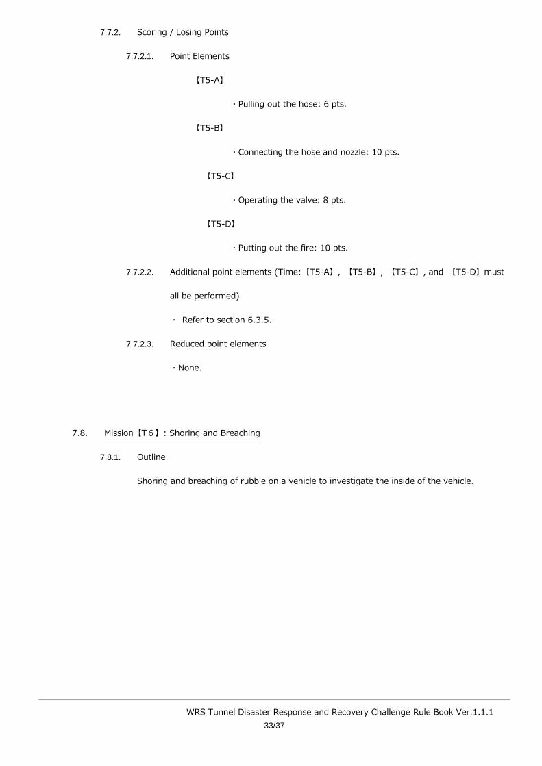
(4) 【T5-D】Move to the fire origin while holding the nozzle connected to the hose.
Turn the nozzle toward the fire and extinguish the fire.
○ Spray water from the designated area (Move to the designated area).
○ Rotate the lever attached to the nozzle to spray water.
○ The torque required to rotate the lever is 2 Nm (the lever rotates with a
minimum torque of 2 Nm)
○ Spray the specified amount of water to extinguish the fire.
○ The flame will gradually spread once the task starts.
WRS Tunnel Disaster Response and Recovery Challenge Rule Book Ver.1.1.1
33/37
7.7.2. Scoring / Losing Points
7.7.2.1. Point Elements
【T5-A】
・Pulling out the hose: 6 pts.
【T5-B】
・Connecting the hose and nozzle: 10 pts.
【T5-C】
・Operating the valve: 8 pts.
【T5-D】
・Putting out the fire: 10 pts.
7.7.2.2. Additional point elements (Time:【T5-A】, 【T5-B】, 【T5-C】, and 【T5-D】must
all be performed)
・ Refer to section 6.3.5.
7.7.2.3. Reduced point elements
・None.
7.8. Mission【T6】: Shoring and Breaching
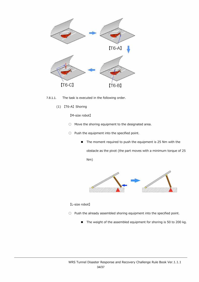
7.8.1. Outline
Shoring and breaching of rubble on a vehicle to investigate the inside of the vehicle.
WRS Tunnel Disaster Response and Recovery Challenge Rule Book Ver.1.1.1
34/37
7.8.1.1. The task is executed in the following order.
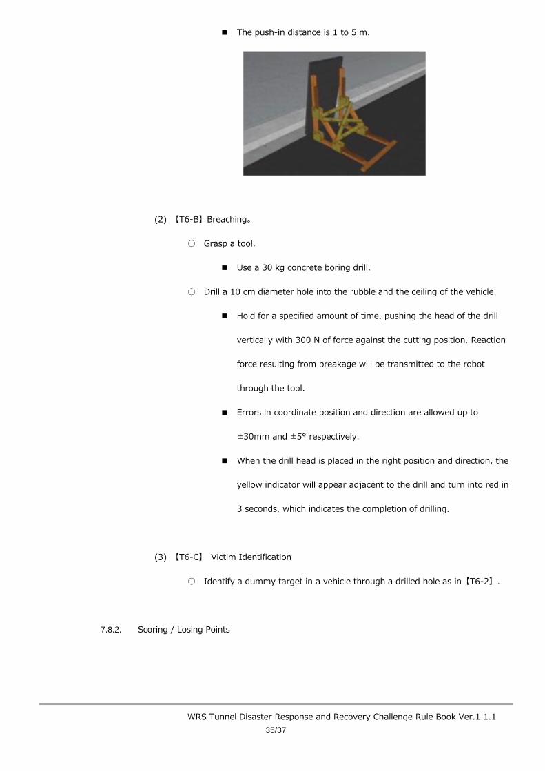
(1) 【T6-A】Shoring
【M-size robot】
○ Move the shoring equipment to the designated area.
○ Push the equipment into the specified point.
■ The moment required to push the equipment is 25 Nm with the
obstacle as the pivot (the part moves with a minimum torque of 25
Nm)
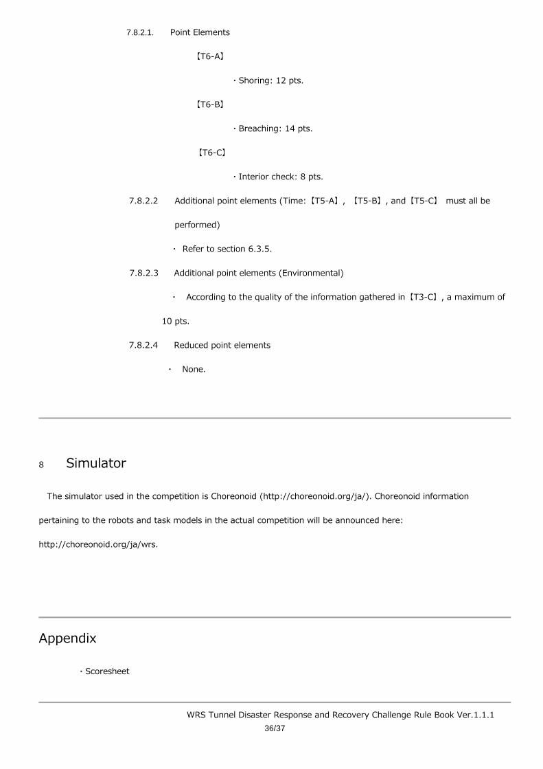
【L-size robot】
○ Push the already assembled shoring equipment into the specified point.
■ The weight of the assembled equipment for shoring is 50 to 200 kg.
WRS Tunnel Disaster Response and Recovery Challenge Rule Book Ver.1.1.1
35/37
■ The push-in distance is 1 to 5 m.
(2) 【T6-B】Breaching。
○ Grasp a tool.
■ Use a 30 kg concrete boring drill.
○ Drill a 10 cm diameter hole into the rubble and the ceiling of the vehicle.
■ Hold for a specified amount of time, pushing the head of the drill
vertically with 300 N of force against the cutting position. Reaction
force resulting from breakage will be transmitted to the robot
through the tool.
■ Errors in coordinate position and direction are allowed up to
±30mm and ±5° respectively.
■ When the drill head is placed in the right position and direction, the
yellow indicator will appear adjacent to the drill and turn into red in
3 seconds, which indicates the completion of drilling.
(3) 【T6-C】 Victim Identification
○ Identify a dummy target in a vehicle through a drilled hole as in【T6-2】.
7.8.2. Scoring / Losing Points
WRS Tunnel Disaster Response and Recovery Challenge Rule Book Ver.1.1.1
36/37
7.8.2.1. Point Elements
【T6-A】
・Shoring: 12 pts.
【T6-B】
・Breaching: 14 pts.
【T6-C】
・Interior check: 8 pts.
7.8.2.2 Additional point elements (Time:【T5-A】, 【T5-B】, and【T5-C】 must all be
performed)
・ Refer to section 6.3.5.
7.8.2.3 Additional point elements (Environmental)
・ According to the quality of the information gathered in【T3-C】, a maximum of
10 pts.
7.8.2.4 Reduced point elements
・ None.
8 Simulator
The simulator used in the competition is Choreonoid (http://choreonoid.org/ja/). Choreonoid information
pertaining to the robots and task models in the actual competition will be announced here:
http://choreonoid.org/ja/wrs.
Appendix
・Scoresheet
WRS Tunnel Disaster Response and Recovery Challenge Rule Book Ver.1.1.1
37/37
Revision History
Ver.1.0 (October 24, 2017): First edition.
Ver.1.0.1 (March 1, 2018): Added information about the simulator (Chapter 8).
Ver.1.0.2 (June 8, 2018): Changed task numbers. Revised content.
Ver.1.0.3 (June 20, 2018): Revised content.
Ver.1.0.4 (August 30, 2018): Revised content.
Ver.1.1.0 (September 7, 2018): Revised content.
Ver.1.1.1 (September 7, 2018): Revised content.