Embed Size (px)
Citation preview

The AMSAT Journal May/June 2014 www.amsat.org 25
WRAPS Rotor Enhancements Add a Second Beam and Circular Polarization
Mark Spencer, WA8SME ([email protected])ARRL Education and Technology Program
The author shown with his original WRAPS rotator project described in the January 2014 QST. This article shows how to add the capability to modify WRAPS with two beams and add the capability for circular polarization.
Part 1: Tricked-Out WRAPS Satellite Antenna Rotator
Adds a Second Beam
The January 2014 issue of QST published my article about the WRAPS (Wobbler RadFxSat Antenna Pointing
System) rotator system, an inexpensive, portable azimuth and elevation rotor for use with a simple tripod and light weight antennas such as the popular Arrow and Elk handhelds. The WRAPS system is ideal for easy transport and setup of educational demonstrations such as the new FUNcube/AO-73 and upcoming Fox-1, as well as Field Day operations and grid square expeditions.
To support amateur radio in space and broaden availability of the article in support of the ARRL Education and Technology Program, the ARRL has made this article available at:
http://ww2.amsat.org/xtra/wraps-mark-spencer-wa8sme-qst-jan-2014-copyright-arrl.pdf
Additional information about WRAPS is available on-line for ARRL members at:
http://www.arrl.org/qst-in-depth
The WRAPS Master CD which comes with the board includes detailed parts information, PIC microcontroller software, construction information etc may be downloaded from:
http://ww2.amsat.org/xtra/WRAPS%20CD%20Master.zip
Four related videos of the WRAPS system and operation may be found on the AMSAT YouTube channel:
https://www.youtube.com/user/AMSATNA
Hams, by their very nature, want to make their equipment do things that the equipment was not designed to do…myself included. A number of the builders of the WRAPS had made requests and suggestions on how to improve the system. One suggestion which caught my interest lead me to revisit the WRAPS to “trick it out” to handle two Arrows to get circular polarization capabilities. Figure 1 and 2 illustrate the result.
A wordy article is not necessary for this modification of the original WRAPS rotator so the meat of this project will be illustrated through pictures. I used most of the existing
(right) Figure 1: The Tricked Out WRAPS can handle two small beam antennas.
(left) Figure 2: Add phasing l ines for circular polarization.

26 The AMSAT Journal May/June 2014 www.amsat.org
WRAPS project parts. Figures 3, 4, 5, and 6 illustrate the modifications so two antennas can be used.
The added parts to make it a dual antenna capable rotator cost an additional $80 over the price of the parts for the basic WRAPS. The parts list is included in Figure 7. It is still pricy, still portable and battery operated, but it is what it is.
There is no modification to the board or the firmware so it is a straight mechanical modification. Someone could make it into a 180 degree elevation rotator, but it would require an adjustment of the EL gearing to accommodate that added 90 degrees. The firmware should not need to be changed.
If you would like additional information, please contact me at [email protected] or at 860-381-5335 (I am located in the United States Eastern Time Zone).
The tricked out WRAPS was on display at the ARRL/ETP booth in Dayton Hamvention for show and tell. The original WRAPS was on display at the AMSAT booth.
AMSAT-NA is pleased to be able to offer the key electronic components in the AMSAT Store:
http://store.amsat.org/catalog/
What you get:• Unpopulated circuit board
• Programmed PIC chip
• CD-ROM containing instructions and support materials to complete the project
WRAPS requires a tracking program supporting the EASYCOM protocol to provide pointing information. Programs, including free versions, are available for Linux, Mac, and Windows operating systems. AMSAT-NA has fully featured p rog rams ava i l ab l e fo r Mac and Windows machines at the AMSAT Store. Making complete systems or full kits available is not currently contemplated.
Figure 3
Figure 4
Figure 5 Figure 6

The AMSAT Journal May/June 2014 www.amsat.org 27
LHCP circular polarization by inserting a ¼ wavelength delay line in the center of the interconnecting cable harness that is made of two coax transformer sections and the phasing line. To switch to the opposite polarity, the rig feed point is simply shifted to the other side of the ¼ wavelength delay line (Figure 9). This arrangement is complicated because the impedance at the ends of the 75Ω transformer sections is approximately 100Ω and the delay line impedance needs to match that impedance. One hundred ohm coax is not a common coax, but short sections for phasing lines can be homebrewed out of standard coax.
Homebrew coax of non-standard impedance
The impedance of coax is dependent on three factors; the dielectric constant of the insulating material between the inner conductor and the outer shield, the diameter of the insulating material (the internal diameter of the outer shield braid), and the diameter of the center conductor (Figure 10). The relationship between these coax characteristics are detailed in equation 1 (the cited web location has a nice coax impedance calculator to help play with the math). In this project, I modified lengths of
RG-8 Mini Foam coax to create coax with an impedance of approximately 100Ω by replacing the center conductor with thinner, Cat-5 conductor wire.
Part 2: Circling the WRAPS: This Modification Shows How to Add Circular Polarization
to Two Antennas
The purpose of this article is to describe a technique I used to make a ¼ wavelength delay-phasing line of non-standard impedance out of standard 50 Ω coax to circularly polarize a pair of Arrow antennas.
I have received some very positive and inspirational feedback from the builders of the WRAPS portable satellite antenna rotator system that is described in January 2014 QST. The feedback first inspired the tricked out WRAPS which is a modification of the original design to handle two Arrow class antennas mounted on a horizontal boom. Next, the tricked out WRAPS inspired me to look into a polarity switching system to change between RHCP and LHCP by the flip of a switch. This idea was combined with a previous project I developed, the minimalist preamp, that was described a while back in the November/December 2012 AMSAT Journal. The result is a polarity and frequency band agile antenna-mounted preamp for portable satellite operations.
Figure 8 illustrates one way to achieve
Figure 7: Parts list for the Tricked Out WRAPS rotator.
Equation 1.From: http://www.microwaves101.com/
encyclopedia/calcoax.cfm
These are the specifications for RG-8 Mini Foam cable:
• The insulation is foam polyethylene with a dielectric constant (Er) of 1.16.
• The insulator diameter (D) is 0.157”.
The diameter of one strand of a Cat-5 Cable (d) is 0.02 inches. Plugging these values into equation 1 results in an impedance for the modified coax of 114Ω. This is a pretty good match to the 112Ω output of the transformer lines (using standard 75Ω RG-6 coax). The problem is how to replace the center conductor of the RG-8 Mini coax?
The following is the process that I used to

28 The AMSAT Journal May/June 2014 www.amsat.org
replace the center conductor of short lengths of RG-8 Mini coax to make the phasing lines (refer to Figures 11 and 12).
1. Cut a section of RG-8 Mini cable that is slightly longer than what you estimate the electrical ¼ wavelength will be. I simply use the standard antenna wavelength formula. The actual velocity factor of your homebrew cable will be pretty good, so don’t under estimate this length [i.e., the velocity factor is much better than 0.6].
2. Carefully remove the outer covering of the RG-8 Mini coax using care not to score or cut the underlying braided shield.
3. Scrunch the braided shield like a Chinese Finger Trap so that the shield can be removed from the foam center insulator.
4. Using a knife to make sharp and clean edges, cut the foam insulating material into short sections so that the sections can be pulled off the center conductor (a little trial and error is appropriate, for me, lengths of about 5 inches seemed to work).
5. Strip the insulation off a length of one strand of a Cat-5 Cable conductor, the cable I had on hand had a solid conductor.
6. Slide the foam insulation sections over the new center conductor.
7. Using the appropriate size of heat shrink tubing, put a short section of heat shrink tubing over the joints in the foam insulation, heat to shrink.
8. Slide the braid shield over the form insulation and stretch out to the length of the modified cable.
9. Install a crimp BNC connector to one end of the modified cable; you are now ready to determine the electrical ¼ wavelength for the phasing line.
Determining ¼ electrical wavelength
You will need an antenna analyzer (I have the MFJ model) or a SWR/watt meter to determine the electrical ¼ wavelength for the phasing line. If you are absolutely certain of the coax cable’s velocity factor, you could probably apply that velocity factor to reduce the calculated length of a cable to the elec-
Figure 8.
Figure 9.
Figure 10.

The AMSAT Journal May/June 2014 www.amsat.org 29
trical length. In this case, the velocity factor of your homebrew cable is unknown so you will have to use the following procedure.
Make a jig with a mating coax connector for your analyzer or SWR meter (my meters needed a PL259), a 50Ω carbon resistor (small wattage would be fine), and a female BNC connector. Install the resistor in series with the connector center pins using leads as short as practicable. Ground the outer shields of the connectors; the solder lug on the BNC connector works well. What this 50Ω terminating jig does is to allow any odd multiple of ¼ wavelength coax cable, which is open at the other end, regardless of the impedance), to resonate at 50Ω at the meter (jig) input.
Connect your homebrew 100Ω cable section to jig attached to the analyzer or the SWR meter. If you are using an SWR meter, you will need to attach a low power transmitter to the SWR meter to use as an RF source. Set the analyzer or rig to the frequency of interest (2 m, I use 146 MHz; 70 cm, I use 436 MHz). The SWR will read high. Incrementally trim off small sections of the homebrew coax, perhaps ½ inch at a time; as the SWR lowers toward 1:1, start trimming less, perhaps ¼ inch increments. When you reach very close to 1:1 SWR, trim one more short ¼ inch increment (to make up for the BNC connector to be installed later).
To complete the homebrew phasing line, install heat shrink tubing over half of the entire length of the cable snug up against the previously installed BNC, and then shrink the tubing. Slip another section of shrink tubing over the other half of the cable, but do not shrink the tubing yet. Install the other BNC connector. Just to be sure, double check the cable on your SWR setup; it should be close to 1:1 SWR. The final step is the cover the last half of the cable with the shrink tubing, heat to shrink, and you’re done.
Construct the two odd-multiple of ¼ electrical wavelength transformer lines out of RG-6, 75Ω cable (just straight RG-6, not modified). For my WRAPS system, I found that ¾ wavelength transformer lines are required for the 2 meter antennas, and 1¼ wavelength transformer lines are required for the 70 cm antennas to span the distance between the antennas. Install a couple of BNC “T” connectors between the transformers and the delay line. A pictorial representation of the completed antenna feed harness is illustrated in Figure 13. To switch between RHCP and LHCP, simply move your rig feed point from one BNC “T” connector to the other.
(Above): Figure 11. (Below): Figure 12.
30 The AMSAT Journal May/June 2014 www.amsat.org
is described in November/December 2009 AMSAT Journal.)
Operation
The minimalist preamp is broad-banded and covers both the 2 meter and 70 cm bands. I created a circular polarization harnesses for both bands with the BNC “T” connectors on each side of the phasing lines. If I am going to operate a satellite with a UHF uplink and a VHF downlink, I install the preamp on the VHF cable so that the antenna is RHCP when the polarity switching relay is at rest (non-energized) and I connect the transmitter to the BNC connector on the UHF cable for RHCP (vise versa for the UHF down, VHF up). Most of the time, the satellites are RHCP. I find that most of the polarity fades happen early (above AOS) and late (above LOS) in the pass. When a fade is detected, simply flip the polarity switch to energize or de-energize the relay; this action moves the ¼ wavelength delay line back and forth between the antennas and creates the RHCP/LHCP polarity shift. As I mentioned, I mitigate the polarity shifts on the uplink by manipulating the transmitting power to a level appropriate for respectful satellite operations.
Early in my satellite operation experience I used fixed RHCP and I simply accepted the fades. After I upgraded my station and included polarity switching, I could not believe what a difference it makes! By a simple flip of a switch, the signals would go from S-0 to S-9 in many cases; the difference is truly amazing.
I have become a firm proponent of antenna mounted preamps, and now, polarity switching. This relatively inexpensive modification to your portable station just might be the station upgrade you have been looking for to enhance your satellite operating experience.
An expanded discussion of circular polarizing antennas can be found at this web location:
http://ww2.amsat.org/xtra/Polarity%20Switching%20Preamp.pdf
If you have questions or need additional information, please contact me at
Figure 13.
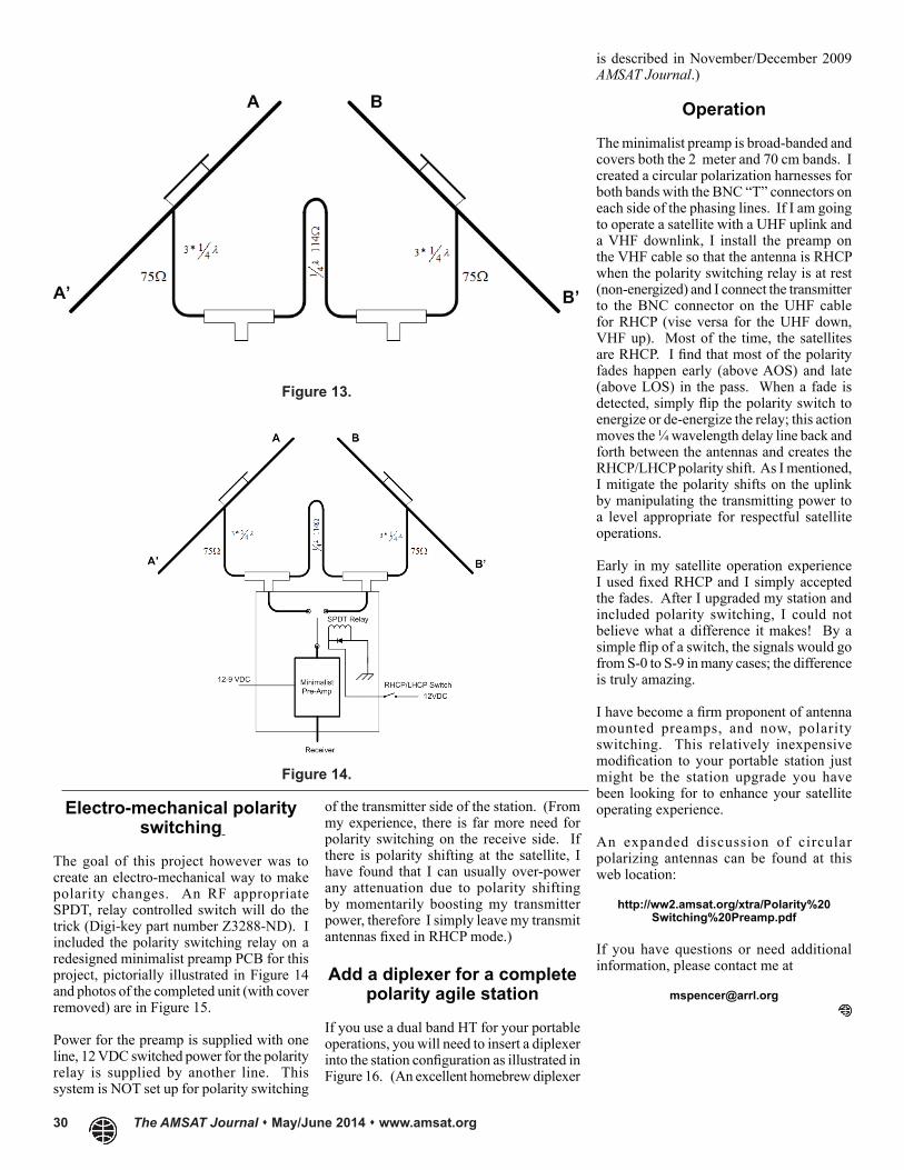
Figure 14.
Electro-mechanical polarity switching
The goal of this project however was to create an electro-mechanical way to make polarity changes. An RF appropriate SPDT, relay controlled switch will do the trick (Digi-key part number Z3288-ND). I included the polarity switching relay on a redesigned minimalist preamp PCB for this project, pictorially illustrated in Figure 14 and photos of the completed unit (with cover removed) are in Figure 15.
Power for the preamp is supplied with one line, 12 VDC switched power for the polarity relay is supplied by another line. This system is NOT set up for polarity switching
of the transmitter side of the station. (From my experience, there is far more need for polarity switching on the receive side. If there is polarity shifting at the satellite, I have found that I can usually over-power any attenuation due to polarity shifting by momentarily boosting my transmitter power, therefore I simply leave my transmit antennas fixed in RHCP mode.)
Add a diplexer for a complete polarity agile station
If you use a dual band HT for your portable operations, you will need to insert a diplexer into the station configuration as illustrated in Figure 16. (An excellent homebrew diplexer

The AMSAT Journal May/June 2014 www.amsat.org 31
(Above): Figure 15. (Below): Figure 16.
Dutch Delfi-C3 6th Year On-Orbit
Wouter Weggelaar, PA3WEG, on behalf of the Delfi-C3 ops-team says that Delfi-C3 has celebrated its 6th birthday on April 28, 2014. The spacecraft is still operational, telemetry only, on 145.870 USB
Delfi-C3 has exceeded its mission lifetime by six times now, and on-board telemetry still does not indicate degradation in performance.
So far, the Delfi-C3 distributed ground station network (DGSN) has collected over 2037513 frames, received by 376 registered radio amateurs and many more on the guest account, using the free RASCAL software. This would not have been possible without the continued support of amateur radio operators.
The WRAPS Circuit Board kit includes:
• Unpopulated circuit board• Programmed PIC chip• CD-ROM containing instructions
and support materials to complete the project
• Additional project details can be found on-line in the product description in the AMSAT Store.
AMSAT will offer both, the original WA8SME Minimalist Preamp, and a new polarity agile preamp (as described in the accompanying article). Watch the AMSAT Store and AMSAT News Service for availability in late July, 2014.
WRAPS Project Parts in the AMSAT Store
http://www.store.amsat.org/catalog