Embed Size (px)
Citation preview
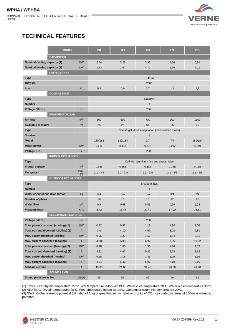
WPHA WPHBA Cooling only Heat pump
SELF CONTAINED HORIZONTAL AIR CONDITIONERS
INS
TA
LL
AT
ION
, O
PE
RA
TIO
N A
ND
MA
INT
EN
AN
CE
MA
NU
AL
04.17 207599 Rev.102
Models: 091│121│141│171│201│251│351│401│501│701│751│1001│1201
Cooling capacities: from 2,4 to 41,0 kW
Heating capacities: from 2,8 to 46,0 kW

2 04.17 207599 Rev.102
COMPACT HORIZONTAL SELF-CONTAINED WATER-TO-AIR UNITS
WPHA / WPHBA
INDEX
INTRODUCTION .......................................................................................................................................................... 3
CONTENTS ....................................................................................................................................................................... 3 STANDARDS AND CERTIFICATIONS .................................................................................................................................. 3 SAFETY PRECAUTIONS ..................................................................................................................................................... 4
RECEPTION ................................................................................................................................................................. 5
INSPECTION WHEN RECEIVING ........................................................................................................................................ 5 RIGGING ........................................................................................................................................................................... 5 STORAGE .......................................................................................................................................................................... 5
INSTALLATION LOCATION ........................................................................................................................................... 6
UNIT SETTLEMENT ........................................................................................................................................................... 6 SERVICE AREA (MM) .......................................................................................................................................................... 6 WEIGHT DISTRIBUTION (KG) ............................................................................................................................................. 6
WPHA / WPHBA HYDRAULIC CIRCUIT AND ITS COMPONENTS ................................................................................... 7
DIAGRAM OF WATER CONNECTION AND COMPONENTS ................................................................................................ 8 WATER CONNECTIONS OF PRESOSTATIC VALVE OPTIONAL ............................................................................................ 9
START UP ...................................................................................................................................................................10
WORKING LIMITS ......................................................................................................................................................11
DRAINAGE ...................................................................................................................................................................... 11 AIR DUCTWORK ............................................................................................................................................................. 12
COMPRESSOR LUBRICANT .........................................................................................................................................13
TECHNICAL FEATURES ................................................................................................................................................14
TECHNICAL SPECIFICATIONS OPTIONAL EC MOTOR ...................................................................................................... 17
REFRIGERANT LOAD ..................................................................................................................................................18
MAINTENANCE ..........................................................................................................................................................19
DIMENSIONS .............................................................................................................................................................20
MOD. 091 – 141 ............................................................................................................................................................. 20 MOD. 171 – 201 ............................................................................................................................................................. 21 MOD. 251 – 401 ............................................................................................................................................................. 22 MOD. 501 – 751 ............................................................................................................................................................. 23 MOD. 1001 – 1201 ......................................................................................................................................................... 24
FAN WITH EC MOTOR (OPTIONAL) ............................................................................................................................25
SAFETY INSTRUCTIONS .................................................................................................................................................. 25 DIAGNOSTICS / FAULTS .................................................................................................................................................. 29
ANNEX: SAFETY FILE R410A .......................................................................................................................................31

3 04.17 207599 Rev.102
COMPACT HORIZONTAL SELF-CONTAINED WATER-TO-AIR UNITS
WPHA / WPHBA
INTRODUCTION CONTENTS Purpose of the Manual This manual has been written to allow proper installation, commissioning and maintenance of the unit. Therefore it is important to read the following instructions paying due attention. The manufacturer declines all responsibility for any damage to persons or things as a result of improper use of the unit and / or failure to observe these instructions.
Preservation Manual This manual and the electric diagram of the unit must be retained and remain available to the operator for further consultation.
Local Safety Standards Follow the local security standards during installation.
Electrical Network Check that electrical network features are in accordance to data shown in the data nameplate of the unit.
Packaging Packaging material (plastic bags, cellular polystyrene, cloves, etc.) constitutes a dangerous source, for that it should be kept out of the reach of children and recycled correctly according to local security standards.
Maintenance Before executing any maintenance operation, cut off the unit power supply. Operations have to be carried out following local security standards.
Periodic Inspections Carry out periodic inspections to detect possible damaged or broken pieces. If they are not repaired it could result in damage to people or stuff.
Incorrect Operation In case of breakdowns or operation faults, turn off unit.
Repairs Reparations should be always realized for trained personal authorized by the manufacturer using original spares. Failure to comply with these warnings could affect the safety features of the unit.
Modifications All manufacturer responsibility is declined when the warranty has been expired in case of electrical and/or mechanical modifications. Alterations in general not expressly allowed and not respecting what is instructed here, they cause the warranty expiration.
Use The unit will be used only for the reason has been conceived. Any other use does not imply any kind of compromise or link for the manufacturer.
Principles of Security on Installation The unit is designed and built so that a risk to health and security for people are not supposed. Suitable project solutions have been adopted to delete possible causes of risk in the system.
Data Actualization Continuous improvements to the product may determine variations in the data given even without notice by the manufacturer.
Refrigerant
This product is hermetically sealed and contains R-410A which is a HFC fluorinated greenhouse gas.
STANDARDS AND CERTIFICATIONS ISO 9001:2008 CERTIFICATION: HIPLUS AIRE ACONDICIONADO S.L always search satisfaction on its customers, it is
accredited in the Quality System ISO 9001:2008 referred to their own productive activity. It is manifested in a continuous
commitment to improve the quality and reliability of all our products; commercial activity, design, source materials,
production and post-sale service, are the way that allows us to accomplish our targets.
CE QUALIFICATION: HITECSA units have CE brand in accordance with the expected for the relevant
community directive, and its last modifications, as well as for each country's national legislation.

4 04.17 207599 Rev.102
COMPACT HORIZONTAL SELF-CONTAINED WATER-TO-AIR UNITS
WPHA / WPHBA
SAFETY PRECAUTIONS
Installation and maintenance of air conditioning equipment can be dangerous because system is it has high temperature of some elements and it includes electrical components.
Only qualified and trained service personnel should install, start up and do maintenance on air conditioning equipment. Not qualified personnel only should do basic maintenance: cleaning filters substitution, etc.
During every visit follow recommendations from the Installation Operation Maintenance, what is shown on unit’s stickers and take general legal safety precautions.
Strictly abide by any and all safety codes.
Use safety goggles, proper work gloves and any other work safety accessory recommended for any particular task.
For brazing operations use a quenching cloth and keep a fire extinguisher at a close distance.
When repairing the unit use only original spare parts and install those properly in the same place where have been located old parts.
Do not install the unit in explosive atmosphere.
These units are designed to operate using 100% recycled air. For installations that use the support of ambient air, please consult with our commercial department.
This product contains flourine-based greenhouse gases. Refrigerant: R410A. PCA: 2088.
Before starting installation, service or maintenance switch off the main system power switch to avoid electrical shock.
Before accessing the inside of the unit through the electric box, it is MANDATORY to
unplug the electrical supply hose that MUST BE FREE of voltage for this operation.
ATTENTION!
ATTENTION!

5 04.17 207599 Rev.102
COMPACT HORIZONTAL SELF-CONTAINED WATER-TO-AIR UNITS
WPHA / WPHBA
RECEPTION
INSPECTION WHEN RECEIVING When the receiving the equipment, it is advisable to examine it carefully.
Inspect the received equipment for damage or missing elements. If units are damaged or shipment is incomplete, immediately file the claim with the shipping company.(First 48h)
Verificar si el voltaje de la placa de la unidad es el correcto y de acuerdo con el suministro eléctrico disponible.
En el caso de detectar cualquier desperfecto o anomalía se recomienda ponerse en contacto con HITECSA.
RIGGING Before moving the unit, make sure that all panels are well fixed and sturdy.
Raise and lower the unit carefully.
During the transport never tip or roll the unit more than 15 degrees. (Fig. 2).
When lifting the unit make sure that it is balanced and stable, keep in mind that the heaviest part is where the compressor is installed.
Always transport the unit in the original packaging to its installation placement. .
STORAGE If the equipment must be stored before installation, certain precautions must be adopted to prevent damage, corrosion or deterioration:
Do not place the machine in areas exposed to ambient temperatures exceeding 50°C and preferably not give direct sunlight.
Minimum storage temperature 5ºC
Maximum relative humidity: 90%
Avoid placing on top of the unit other objects (unless it is done within the limits of the overlay planes indicated on the packaging).
Avoid placing the unit with shrinkable heat protection under the sun, since the pressure of the circuits can assume values that could lead to involving the safety valves.

6 04.17 207599 Rev.102
COMPACT HORIZONTAL SELF-CONTAINED WATER-TO-AIR UNITS
WPHA / WPHBA
INSTALLATION LOCATION
Check if the surface is able to support the unit’s weight.
Verify that the service area is the correct one for that specific model.
Choose a location free of dust and foreign matter which, can clog or damage condenser coil.
Consult and respect all regulations concerning installation of air conditioning systems.
UNIT SETTLEMENT Ensure that the unit is properly leveled.
In the case to place the unit above the bed this must have sufficient surface and strength to support the weight of the
unit.
Make sure the drains are working properly.
Use of dampers is recommended to reduce noise and vibration transmission.
SERVICE AREA (mm)
WEIGHT DISTRIBUTION (kg)
MODEL 1 2 3 4
091 13 13 16 18
121 14 14 16 18
141 14 15 17 19
171 16 17 20 22
201 16 19 20 22
251 21 22 22 25
351 24 26 29 31
401 26 27 30 32
501 38 38 41 43
701 38 38 41 43
751 43 44 46 47
1001 55 56 59 60
1201 61 61 63 65 (3 – 4): Electrical box side

7 04.17 207599 Rev.102
COMPACT HORIZONTAL SELF-CONTAINED WATER-TO-AIR UNITS
WPHA / WPHBA
WPHA / WPHBA HYDRAULIC CIRCUIT AND ITS COMPONENTS Within the hydraulic circuit and its components, the plate heat exchanger is the most delicate part affected, and as a result must follow at least these guidelines:
The installation must be made according to the diagrams in the 200225 document.
The water filter is installed and must contain inside a mesh to retain particles with diameter Ø< 0.5mm.
El mantenimiento tanto del filtro como del interruptor de flujo deberá realizarse dentro de unos periodos en los cuales se eviten apósitos que puedan bloquearlo.
The maintenance of both the filter and the flow switch must be done within periods in which the locking dressings are avoided.
The input and output water indication must be respected and install if necessary a bypass valve.
When working with open circuits in which water quality is not correct and the problem is indicated in the table, it is advisable to install a secondary exchanger to prevent deterioration.
Element contained in water
Concentración por mg/l
Effects of a higher value Effects of a lower value
Suspended solids Variable Can erode the material No effects were observed
Conductivity ≤ 500 µs/cm No effects were observed -
> 500 µs/cm - Not recommended
NH3 2 - 20 Not recommended No effects were observed
Chlorides ≤ 300 - No effects were observed
> 300 Corrosive capacity -
Iron ≤ 10 Not effects were observed -
> 10 - Corrosive capacity
Carbonic acids 20 - 50 Corrosive capacity Not recommended
PH 6 - 9 Corrosive capacity No effects were observed
Sulphates 70 - 300 No effects were observed Corrosive capacity
Langelier -0,5 - +0,5 Water with tendency to create
incrustations Water with corrosive
tendency

8 04.17 207599 Rev.102
COMPACT HORIZONTAL SELF-CONTAINED WATER-TO-AIR UNITS
WPHA / WPHBA
DIAGRAM OF WATER CONNECTION AND COMPONENTS
3
4
7
8
11
12
Flexible connection
Condensates drain tube
Dry cooler
Auto air purge
Pressure gauge Water pump
15 Flow switch
1
2
5
6
9
10
Unit WPHA/BA
Air duct
Glove valve
Water line
Water filter Thermometer
13
14
Drainage
Expansion tank
It is mandatory to install the flow switch in the water inlet of the machine and with a previous section of 1.5 m in a straight line without changing section to ensure that the flow rate of water / fluid is laminated.
Failure to comply with these guidelines causes loss of the equipment warranty.
ATTENTION!

9 04.17 207599 Rev.102
COMPACT HORIZONTAL SELF-CONTAINED WATER-TO-AIR UNITS
WPHA / WPHBA
WATER CONNECTIONS OF PRESOSTATIC VALVE OPTIONAL
*For TH-TUNE maneuver
NOTES
The pressure tap of the presostatic valve must be connected to the high pressure outlet of the unit.
The graphs show connections for heat pump units. In the case of cooling only units, do not mount the solenoid valve.
While mounting the presostatic valve, the performance of the flow switch on the compressor start-up must be time during one minute, to let the valve act.

10 04.17 207599 Rev.102
COMPACT HORIZONTAL SELF-CONTAINED WATER-TO-AIR UNITS
WPHA / WPHBA
START UP
At first, start up the water pump for a few minutes.
Stop the water pump and notice if the auto purge is working. Repeat this operation 10 times.
If we proceed in this way, all the existing air will go out in the system and the water system will be filled.
The next step is to disconnect the mesh filter and clean it. The performance of the system will improve, because the mesh filter valve has a high pressure drop.
The start-up must be performed by qualified technical personnel in air conditioners.
It is necessary to make a start-up check list: Note inlet and outlet temperatures, voltage, amperage of the compressor and fan motor, as well as, discharge pressure of the compressor.
Remember to clean the air-filters after the first 4 hours of performance.
Closely supervise at least 3 cooling cycle operations.
It is very important to evacuate air from the system and clean dirt particles of the water circuit. The two
operations must be done at the same time.
ATTENTION!
Ensure that all electrical connections are well tightened.
Check if all panels are firmly secured with screws.
Verify if there is no refrigerant or oil leakage.
Verify if the unit is installed on level.
Verify is there is enough space for service and maintenance.
Check if the drain holes in the unit are not blocked. Verify that the valves work correctly.
Check if the water pipe system allows drainage to repair or stop.
Check if the crankcase heater of each compressor has been energized at least 24 hours before unit start up.
Check if the air filters are clean and correctly mounted.
Check grills, diffusers, air ducts and tarpaulins.
Ensure that the power supply is in accordance with what is stated on the serial plate.
Verify that fans are rotating in the correct direction.
PRIOR TO START UP
1
2
3
4
5
6
Power supply + Neutral (091- 251 *Monophasic) (351-1201 **Triphasic)
Ground
Cranckcase heater 230/1/50 Delay fuses or circuit curve D
Main switch
Remote control
11 04.17 207599 Rev.102
COMPACT HORIZONTAL SELF-CONTAINED WATER-TO-AIR UNITS
WPHA / WPHBA
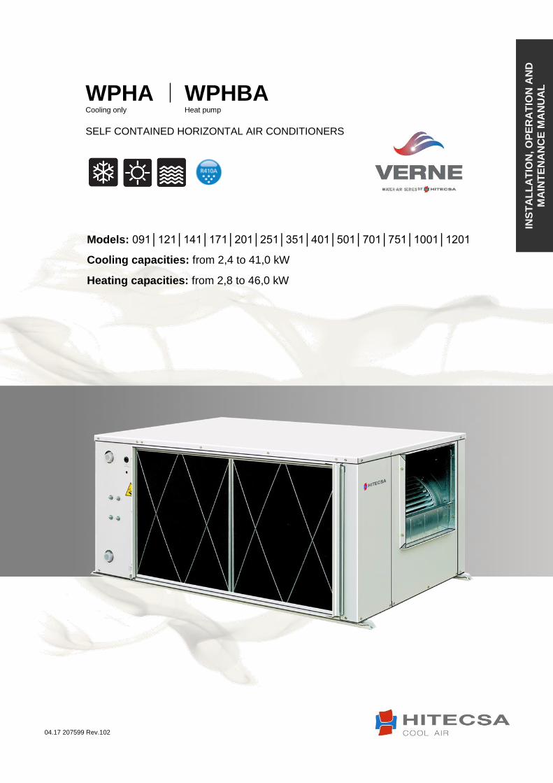
WORKING LIMITS
COOLING CYCLES
TEMPERATURE MIN MAX
Dry indoor air 19ºC 31ºC
Wet indoor air 15ºC 21ºC
Water inlet 15ºC * 45ºC **
*For water inlets lower than 25ºC it is necessary to install the presostatic valve accessory. **On request units can be manufactured to 50 ºC.
HEATING CYCLES
TEMPERATURE MIN MAX
Dry air inlet 18ºC 24ºC
Water inlet 12ºC 27ºC
The electrical power supply of the unit should agree with data on the plate.
Unit start-up at incorrect voltage and damages resulting from that are not covered by Hitecsa guarantee.
When making electrical connections always use the unit’s wiring diagram.
Verify that the compressor crankcase heater can be energized before unit start up.
Unit current supply should be within ±10% of Voltage and Amperes indicated on the unit nameplate.
Do not operate unit at different current from the one shown on unit plate.
The installer has to install line protection elements according to local laws and regulations.
The interconnecting wires have to be in protection tube or inside groove channel.
DRAINAGE
The indoor drainage isfitted with 3/4" gas connections, male (MPT).
Condensate evacuation line diameter should be equal or larger than unit drain connection depending on line length and general building configuration.
The condensate line should be pitched a minimum 2% for proper water evacuation.
If the drain line is at below 0 temperatures, then is necessary to install thermal insulation or an electric wire heater to prevent freezing which would damage the tube
It is convenient to install a trap with proper dimensions.
Disconnect the main power switch before any intervention.
ATTENTION!
Before access inside the unit through the electric box, it is MANDATORY to unplug the
electrical supply hose that MUST BE FREE of voltage for this operation.
ATTENTION!
DIMENSIONS

12 04.17 207599 Rev.102
COMPACT HORIZONTAL SELF-CONTAINED WATER-TO-AIR UNITS
WPHA / WPHBA
AIR DUCTWORK
Air ducts dimensions are determined in relation to air flow and the unit’s available static pressure.
Qualified technician should make air duct design.
Use air ducts made of non-flammable material, which in case of fire will not emit toxic gases.
Use flexible connections between air ducts and the unit to avoid vibrations and noise transmission.
Indoor fan transmission adjustment
Adjust transmission in such a way that indoor motor consumption comes to nominal value.
If consumption is below nominal value it means unit air flow is too low.
To change fan speed:
1. In order to remove belt, move motor along its track. 2. Loose pulley set screws and, if necessary, move flange. 3. Tighten set screws. 4. Place belt in pulley channel. 5. Tighten belt using tensor screw.
To align fan and motor pulleys:
1. Loose fan pulley set screw. 2. Slide fan pulley along the shaft and align with motor using a ruler. Make sure that is parallel to the belt. 3. Tighten fan pulley setscrews.
To adjust belt tension
1. Loose motor mounting plate bolts and slide it. 2. Belt flexion in millimeters is estimated by dividing S by 40.
INCORRECT
INCORRECT INCORRECT ALIGNEMENT
CORRECT RULER POSITION
1. Motor 2. Motor pulley 3. Transmission belt 4. Fan pulley 5. Tensor set screw 6. Set screw 7. Fixed flange 8. Movable flange

13 04.17 207599 Rev.102
COMPACT HORIZONTAL SELF-CONTAINED WATER-TO-AIR UNITS
WPHA / WPHBA
COMPRESSOR LUBRICANT
Compressors designed for 410A use POE oils. Each compressor manufacturer is using different oil for its products.
The compressor or system cannot remain open to atmosphere more than 15 minutes..
Compared to the mineral oil used with R22 compressors polyoilester lubricants absorb more than 100 times more the moisture.
UNIT COMPRESSOR BRAND LUBRICANT
LOAD LUBRICANT TYPE VOLTAGE
WPHBA 091 PA89M1C –
4DZDE GMCC 0,350 lt ESTER VG74 230 / I / 50
WPHBA 121 PA125G1C –
4FTL1 GMCC 0,400 lt ESTER VG74 230 / I / 50
WPHBA 141 PA150M2A –
7FTS1 GMCC 0,440 lt RB75EA 230 / I / 50
WPHBA 171 PA170M2C – 4ET2 GMCC 0,480 lt ESTER VG74 230 / I / 50
WPHBA 201 PA215M2AS– 4KU GMCC 0,620 lt ESTER VG74 230 / I / 50
WPHBA 251 PA270G2C – 4FT1 GMCC 0,620 lt ESTER VG74 230 / I / 50
WPHBA 351 HRH040U4LP6 DANFOSS 1,33 lt PVE 400 / III / 50
WPHBA 401 HRH049U4LP6 DANFOSS 1,57 lt PVE 400 / III / 50
WPHBA 501 HRH054U4LP6 DANFOSS 1,57 lt PVE 400 / III / 50
WPHBA 701 HLH068T4LC6 DANFOSS 1,57 lt PVE 400 / III / 50
WPHBA 751 HCJ091T4LC6 DANFOSS 2,46 lt PVE 400 / III / 50
WPHBA 1001 HCJ121T4LC6 DANFOSS 2,46 lt PVE 400 / III / 50
WPHBA 1201 SH140A4ALC DANFOSS 3,3 lt POE – 160 SZ 400 / III / 50
14 04.17 207599 Rev.102
COMPACT HORIZONTAL SELF-CONTAINED WATER-TO-AIR UNITS
WPHA / WPHBA
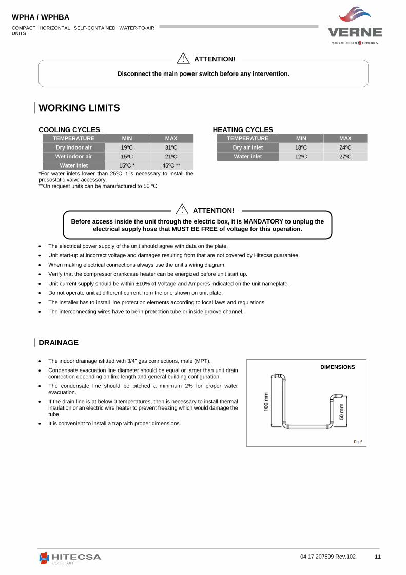
TECHNICAL FEATURES
MODEL 091 121 141 171 201
CAPACITIES
Nominal cooling capacity (1) KW 2.44 3,26 3,93 4,86 5,91
Nominal heating capacity (2) KW 2,83 3,87 4,72 5,56 7,11
REFRIGERANT
Type R-410A
GWP (3) 2088
Load Kg 0,5 0,6 0,7 1,1 1,2
COMPRESSOR
Type Rotative
Number 1
Voltage (50Hz~) V 230.I
EVAPORATOR FAN
Air flow m3/h 500 600 700 900 1100
Available pressure Pa 25 25 54 25 25
Type Centrifugal, double aspiration (incorporated motor)
Number 1
Model 180/184 180/184 7/7 7/7 180/184
Motor power KW 0,115 0,115 0,072 0,072 0,150
Voltage (Hz~) V 230.I
INDOOR EXCHANGER
Type Coil with aluminum fins and copper tube
Frontal surface m2 0.165 0.165 0.165 0.188 0.188
Fin spaced mm –
(“) 2.1 - 3/8 2.1 - 3/4 2.1 - 3/8 2.1 - 3/8 2.1 - 3/8
OUTDOOR EXCHANGER
Type Brazed plates
Number 1
Water connections (Gas thread) (“) 3/4 3/4 3/4 3/4 3/4
Number of plates 16 16 16 22 22
Water flow m3/h 0,5 0,68 0,83 0,99 1,23
Pressure loss KPa 8,72 15,46 22,42 17,90 26,81
ELECTRICAL FEATURES
Voltage (50Hz~) V 230.I
Total power absorbed (cooling) (1) KW 0,72 0,97 1,12 1,14 1,58
Total current absorbed (cooling) (1) A 3,0 4,10 4,93 5,08 7,51
Max. power absorbed (cooling) KW 0,96 1,27 1,52 1,54 2,19
Max. current absorbed (cooling) A 4,38 5,83 6,97 7,95 11,32
Total power absorbed (heating) (2) KW 0,78 1,05 1,31 1,26 1,79
Total current absorbed (heating) (2) A 3,22 4,67 5,87 5,63 8,52
Max. power absorbed (heating) KW 0,88 1,18 1,36 1,39 1,93
Max. current absorbed (heating) A 4,04 5,42 5,96 7,19 9,99
Start-up current A 19,60 21,60 34,40 26,50 43,70
SOUND LEVEL
Sound pressure at 2m dB(A) 58 58 59 60 62
(1) COOLING: Dry air temperature: 27ºC. Wet temperature indoor air 19ºC. Water inlet temperature 30ºC. Water outlet temperature 35ºC (2) HEATING: Dry air temperature 20ºC. Wet temperature indoor air 14ºC. Condenser water inlet temperature 20ºC. (3) GWP: Global warming potential (climatic) of 1 kg of greenhouse gas relative to 1 kg of CO2, calculated in terms of 100-year warming potential.

15 04.17 207599 Rev.102
COMPACT HORIZONTAL SELF-CONTAINED WATER-TO-AIR UNITS
WPHA / WPHBA
MODEL 251 351 401 501
CAPACITY
Nominal cooling capacity (1) KW 7,55 11,50 13,30 16,9
Nominal heating capacity (2) KW 9,23 14,15 16,36 18,89
REFRIGERANT
Type R-410A
GWP (3) 2088
Load Kg 2,3 2,5 2,8 3,2
COMPRESSOR
Type Rotative Scroll
Number 1
Voltage (50Hz~) V 230.I 400.III
EVAPORATOR FAN
Air flow m3/h 1500 2000 2300 2800
Available pressure Pa 37 37 60 50
Type Centrifugal, double aspiration (incorporated motor) Centrifugal,
motor transmission
Number 1
Model 7/7 9/9 10/10 10/10
Motor power KW 0,147 0,200 0,245 0,550
Voltage (Hz~) V 230.I 400.III 400.III 400.III
INDOOR EXCHANGER
Type Coil with aluminum fins and copper tube
Frontal surface m2 0,252 0,252 0,252 0,45
Fin spaced mm – (“) 1,8 - 3/8 1,8 - 3/4 1,8 - 3/8 2,1 - 3/8
OUTDOOR EXCHANGER
Type Brazed plates
Number 1
Water connections (Gas thread) (“) 3/4 3/4 3/4 1 1/4
Number of plates 42 42 42 32
Water flow m3/h 1,56 2,41 2,78 3,41
Pressure loss KPa 15,07 34,30 44,80 21,75
ELECTRICAL FEATURES
Voltage (50Hz~) V 230.I 400.III+N 400.III+N 400.III+N
Total power absorbed (cooling) (1) KW 1,84 2,87 3,31 3,37
Total current absorbed (cooling) (1) A 8,84 6,18 5,80 6,70
Max. power absorbed (cooling) KW 2,59 5,23 4,95 6,32
Max. current absorbed (cooling) A 13,42 8,99 8,50 10,86
Total power absorbed (heating) (2) KW 1,86 3,10 3,60 3,96
Total current absorbed (heating) (2) A 9,00 6,20 5,88 7,44
Max. power absorbed (heating) KW 2,56 4,84 4,55 5,38
Max. current absorbed (heating) A 13,28 8,32 7,81 9,24
Start-up current A 61,30 50,80 61,27 71,27
SOUND LEVEL
Sound level pressure at 2m dB(A) 63 64 64 65
(1) COOLING: Dry air temperature: 27ºC. Wet temperature indoor air 19ºC. Water inlet temperature 30ºC. Water outlet temperature 35ºC (2) HEATING: Dry air temperature 20ºC. Wet temperature indoor air 14ºC. Condenser water inlet temperature 20ºC. (3) GWP: Global warming potential (climatic) of 1 kg of greenhouse gas relative to 1 kg of CO2, calculated in terms of 100-year warming potential.

16 04.17 207599 Rev.102
COMPACT HORIZONTAL SELF-CONTAINED WATER-TO-AIR UNITS
WPHA / WPHBA
MODEL 701 751 1001 1201
CAPACITY
Nominal cooling capacity (1) KW 20,36 25,93 35,40 41,06
Nominal heating capacity (2) KW 23,07 30,60 39,82 46,41
REFRIGERANT
Type R-410A
GWP (3) 2088
Load Kg 3,6 4,2 5,0 6,3
COMPRESSOR
Type Scroll
Number 1
Voltage (50Hz~) V 400.III
EVAPORATOR FAN
Air flow m3/h 3400 4300 6200 7000
Available pressure Pa 50 62 75 75
Type Centrifugal, motor transmission
Number 1
Model 10/10 12/9 12/12 15/15
Motor power KW 0,55 0,75 1,50 1,10
Voltage (Hz~) V 400.III
INDOOR EXCHANGER
Type Coil with aluminum fins and copper tube
Frontal surface m2 0,45 0,45 0,84 0,84
Fin spaced mm – (“) 2,1 - 3/8 2,1 - 3/8 2,1 - 3/8 2,1 - 3/8
OUTDOOR EXCHANGER
Type Brazed plates
Number 1
Water connections (Gas thread) (“) 1 1/4 1 1/4 1 1/4 1 1/4
Number of plates 32 32 52 52
Water flow m3/h 4,13 5,32 7,18 8,39
Pressure loss KPa 30,90 49,03 37,1 49,35
ELECTRICAL FEATURES
Voltage (50Hz~) V 400.III+N
Total power absorbed (cooling) (1) KW 4,26 5,85 7,52 8,90
Total current absorbed (cooling) (1) A 9,27 11,96 16,18 18,05
Max. power absorbed (cooling) KW 8,94 10,20 13,39 14,75
Max. current absorbed (cooling) A 15,36 17,53 23,01 25,34
Total power absorbed (heating) (2) KW 4,94 7,01 8,37 10,10
Total current absorbed (heating) (2) A 10,21 12,76 17,11 19,36
Max. power absorbed (heating) KW 7,71 8,50 12,03 12,99
Max. current absorbed (heating) A 13,25 14,60 20,67 22,32
Start-up current A 88,20 126,60 128,50 149,60
SOUND LEVEL
Sound level pressure at 2m dB(A) 68 68 69 70
(1) COOLING: Dry air temperature: 27ºC. Wet temperature indoor air 19ºC. Water inlet temperature 30ºC. Water outlet temperature 35ºC (2) HEATING: Dry air temperature 20ºC. Wet temperature indoor air 14ºC. Condenser water inlet temperature 20ºC. (3) GWP: Global warming potential (climatic) of 1 kg of greenhouse gas relative to 1 kg of CO2, calculated in terms of 100-year warming potential.
17 04.17 207599 Rev.102
COMPACT HORIZONTAL SELF-CONTAINED WATER-TO-AIR UNITS
WPHA / WPHBA
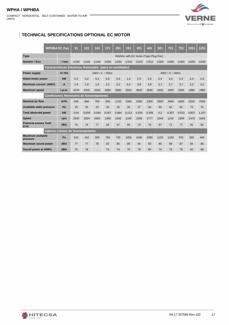
TECHNICAL SPECIFICATIONS OPTIONAL EC MOTOR
WPHBA EC Fan 91 121 141 171 201 251 351 401 501 701 751 1001 1201
Type RADIAL with EC motor (Type Plug-Fan)
Number / Size - / mm 1/190 1/190 1/190 1/250 1/250 1/310 1/310 1/310 1/400 1/400 1/400 1/450 1/450
Características Eléctricas Nominales (para un ventilador)
Power supply V/~/Hz 230V / 1~ / 50Hz 400V / 3~ / 50Hz
Rated motor power kW 0,2 0,2 0,2 0,5 0,5 1,4 2,5 2,5 2,4 2,4 2,4 2,0 2,0
Maximum current (400V) A 1,9 1,9 1,9 2,2 2,2 6,0 3,8 3,8 3,7 3,7 3,7 3,2 3,2
Maximum speed r.p.m. 4240 4240 4240 3080 3080 2920 3640 3640 2400 2400 2400 1880 1880
Condiciones Nominales de funcionamiento
Nominal air flow m3/h 500 600 700 900 1100 1500 2000 2300 2800 3400 4300 6200 7000
Available static pressure Pa 25 25 25 25 25 25 37 50 50 62 62 75 75
Total absorved power kW 0,04 0,059 0,084 0,057 0,084 0,113 0,226 0,309 0,2 0,307 0,513 0,827 1,107
Speed rpm 2500 2924 3365 1368 1640 1190 1558 1777 1044 1242 1509 1476 1643
Potencia sonora Total (Lw)
dBA 70 74 77 63 67 65 73 76 67 71 77 81 84
Valores Límites de funcionamiento
Maximum available pressure
Pa 515 410 300 760 700 1050 1630 1580 1150 1100 975 580 400
Maximum sound power dBA 77 77 78 82 80 89 94 93 90 88 87 84 86
Sound power at 400Pa dBA 75 76 - 73 74 75 78 80 74 76 79 82 86

18 04.17 207599 Rev.102
COMPACT HORIZONTAL SELF-CONTAINED WATER-TO-AIR UNITS
WPHA / WPHBA
REFRIGERANT LOAD
The unit is shipped with a full charge of refrigerant 410A for operation.
If it is necessary to add or recover 410A refrigerant, always do it in LIQUID state. Charging by mistake refrigerant in gas or vapor form will result in wrong mixture conditions.
Due to the high pressure and rapid evaporation of R410A, the refrigerant cannot be maintained in the liquid phase within the filling cylinder when this method is used, generating bubbles in the glass scale and difficulty to read.
Repair immediately all refigerant leaks.
Never overcharge the system
Never use the compressor as a vacuum pump
In the event that during the operation, refrigerant loss symptoms appear, is necessary to do the leak test. The leak detectors are usually used with CFC and HCFC, they don’t work with R4104, since there is no chlorine in its composition. The leak detector for R134A may be used, but the detector sensitivity will be less (Adjusting the sensivity to 1 for R134A, the level for R410A will drop to 0,6).
To detect small leaks, it is necessary a leak detector for HCF. R410A sensitivity is about 23 g / year.
If a gas leak is found, it will be necessary to extract and completely recover the refrigerant charge. Pressurize the system with dry nitrogen. If no leakage is detected, then do the vacuum and charge again with refrigerant.
Never use oxygen for pressurizing in leaking test. Oxygen reacts violently with oil and
can cause explosion and damage, injury or even death.
If it is necessary to weld, first fill the circuit with dry nitrogen. The 410A refrigerant
burning turns out in toxic gas emission.
ATTENTION!
ATTENTION!

19 04.17 207599 Rev.102
COMPACT HORIZONTAL SELF-CONTAINED WATER-TO-AIR UNITS
WPHA / WPHBA
MAINTENANCE
It is advisable to make periodic maintenances of system operation and installation depending on the use, as well as annual revisions.
Coils: At least once a year clean condenser coils with water and detergent and later dry with air at a low pressure. Never clean coil with wire brush.
Indoor fans: Check the direction of rotation of the fans, verify their carriers. Check the transmission elements and the operating status.
Drainage system: Check if openings in the unit base for rain and defrost water evacuation are not blocked.
Refrigeration circuit: Check for oil or refrigerant leakage, noise, various system elements vibrations. Take temperature and pressure readings and record it on the maintenance form.
Electrical circuit: Make sure that all electrical cables are properly tightened. Be sure that there are not faulty terminals, conctactors, etc. Take the measurements of the volts and amperes of each phase of every compressor and fan motor. Verify the starting current. Check the operation of all relays, pressostats, phase sequence relay (of scroll compressor).
Air filters: Clean air filters after 4 hours of system operation and every 3 months (Or more depending on application) Filters can be cleaned by immersion in warm water with soap, later washed in clean water and dry.
Heat exchanger: It is necessary, at least once a year, clean the heat exchanger. The heat exchanger is cleaned by circulating the cleaning liquid inside and if possible in the opposite direction. An acid mixture at 5% is used (5% oxalic acid). Introduce the cleaning fluid through the exchanger. After this, the circuit should be cleaned with plenty of water to remove traces of acid. Refill with new water and start up the unit.
Before performing service or maintenance operations of unit, turn off main power switch to avoid personal injury and put lock on power switch to avoid that any person other than the maintenance technician can switch on electrical supply.
ATTENTION!
1 2 3 Heat exchanger Water-Acid solution tank
Water pump

20 04.17 207599 Rev.102
COMPACT HORIZONTAL SELF-CONTAINED WATER-TO-AIR UNITS
WPHA / WPHBA
DIMENSIONS
MOD. 091 – 141
DIMENSIONS (mm)
MODEL A B C D
091-121 131 108 232 86
141 213 56 238 86
WEIGHT (Kg)
MODEL Net weight Packaged
091 60 75
121 62 77
141 65 80
Legend
1 Electrical connections
2 Water inlet
3 External drainage 3/4’’ male
4 Water outlet
5 Air filter
6 Electrical panel
7 Compressor
8 Evaporator turbine
9 Turbine engine
10 Condenser exchanger
11 Evaporator coil
12 Pressure valve connection (opt)
13 Main power switch
AA Panel access

21 04.17 207599 Rev.102
COMPACT HORIZONTAL SELF-CONTAINED WATER-TO-AIR UNITS
WPHA / WPHBA
MOD. 171 – 201
DIMENSIONS (mm)
MODEL A B C D
171 213 100 238 232
201 131 153 232 86
WEIGHT(Kg)
MODEL Net weight Packaged
171 75 90
201 77 92
Legend
1 Electrical connections
2 Water inlet
3 External drainage 3/4’’ male
4 Water outlet
5 Air filter
6 Electrical panel
7 Compressor
8 Evaporator turbine
9 Turbine engine
10 Condenser exchager
11 Evaporator coil
12 Pressure valve connection (opt)
13 Main power switch
AA Panel access

22 04.17 207599 Rev.102
COMPACT HORIZONTAL SELF-CONTAINED WATER-TO-AIR UNITS
WPHA / WPHBA
MOD. 251 – 401
WEIGHT (Kg)
MODEL Net weight Packaged
251 90 105
351 110 125
401 115 130
DIMENSIONS (mm)
MODEL A B C D
251 213 146 238 98
351 266 88 306 98
401 293 37 238 98
Legend
1 Electrical connections
2 Water inlet
3 External draianage 3/4’’ male
4 Water outlet
5 Air filter
6 Electrical panel
7 Compressor
8 Evaporator turbine
9 Turbine engine
10 Condenser exchanger
11 Evaporator coil
12 Pressure valve connection (opt)
13 Main power switch
AA Panel access

23 04.17 207599 Rev.102
COMPACT HORIZONTAL SELF-CONTAINED WATER-TO-AIR UNITS
WPHA / WPHBA
MOD. 501 – 751
DIMENSIONS (mm)
MODEL A B C D
501-701 293 128 338 190
751 345 65 315 190
WEIGHT (Kg)
MODEL Net weight Packaged
501 160 175
701 160 175
751 180 195
8 Evaporator turbine
9 Turbine engine
10 Condenser exchanger
11 Evaporator coil
12 Pressure valve connection (opt)
13 Main power switch
AA Panel access
Legend
1 Electrical connections
2 Water inlet
3 External drainage 3/4’’ male
4 Water outlet
5 Air filter
6 Electrical panel
7 Compressor

24 04.17 207599 Rev.102
COMPACT HORIZONTAL SELF-CONTAINED WATER-TO-AIR UNITS
WPHA / WPHBA
MOD. 1001 – 1201
DIMENSIONS (mm)
MODEL A B C D
1001 347 117 402 200
1201 409 28 478 163
WEIGHT (Kg)
MODEL Net weight Packaged
1001 230 245
1201 250 265
Legend
1 Electrical conenctions
2 Water inlet
3 External drainage 3/4’’ male
4 Water outlet
5 Air filter
6 Electrical panel
7 Compressor
8 Evaporator turbine
9 Turbine engine
10 Condenser exchanger
11 Evaporator coil
12 Pressure valve connection (opt)
13 Main power switch
AA Panel access

25 04.17 207599 Rev.102
COMPACT HORIZONTAL SELF-CONTAINED WATER-TO-AIR UNITS
WPHA / WPHBA
FAN WITH EC MOTOR (OPTIONAL)
SAFETY INSTRUCTIONS
This document contains information to avoid personal and material damage. These instructions are not intended to be complete. If you have questions or problems, our technicians are at your disposal for any queries you wish to make.
Intended Use
Fans are only intended for the transport of air or mixtures which are like air.
All parts that make up the product: Motor CE, Turbine, supports, cables, etc. They can not be separated from each other.
The fans are an indivisible part of the apparatus in which they are mounted or for which they have been sold as accessories or spare parts.
Improper Use
Improper use / reasonably foreseeable misuse
Conveyance of aggressive and explosive gaseous media.
Utilización en áreas expuestas al peligro de explosión previstas para el transporte de gas, nieblas, vapores o mezclas de los
mismos.
Transport of solids or solid fractions in the transport media.
Operation with iced up fan impellers.
Conveyance of abrasive or adhesive media.
Conveyance of liquid media.
Use of the fan and add-on parts (e.g. safety grille) as a resting surface or climbing aid.
Fans with an additional diffuser (rear mounting kit) are not designed to walk on them! The ascent should be done with
auxiliary resources.
Unauthorised constructional modifications to the fan.
Operation of the fan as a safety component or for the performance of safetyrelevant functions in the sense of EN ISO 13849-
1.
Blocking or braking of the fan by inserting objects.
Loosening of fan blade, impeller and balancing weight.
All applications not listed in the intended use.
Any use of another type or that exceeds this scope will be considered an unplanned use, unless it has been contractually agreed. The manufacturer is not responsible for any damage resulting from unintended uses. In that case, the risk lies exclusively with the company or the user.
Do not connect the built-in fans to outlet pipes of gas equipment or other heating equipment.
Built-in fans with VDE approval (see rating plate) are designed to be mounted inside equipment and are not suitable for direct connection to the mains.
Reading these document and complying with all contained instructions –especially the safety notifications contained therein -are considered part of intended use.
To consider is also the documentation of attached components.
Not the manufacturer, rather the operator of the frequency inverter is liable for any personal harm or material damage
arising from non-intended use.
26 04.17 207599 Rev.102
COMPACT HORIZONTAL SELF-CONTAINED WATER-TO-AIR UNITS
WPHA / WPHBA
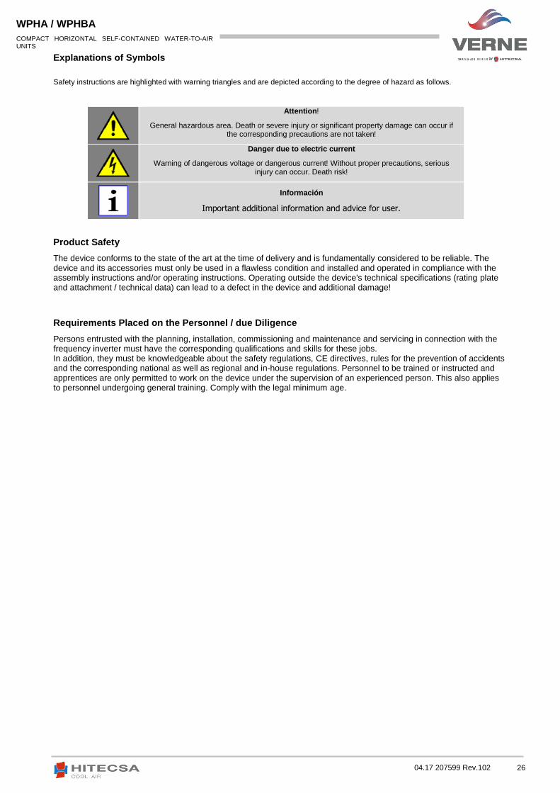
Explanations of Symbols
Safety instructions are highlighted with warning triangles and are depicted according to the degree of hazard as follows.
Attention!
General hazardous area. Death or severe injury or significant property damage can occur if the corresponding precautions are not taken!
Danger due to electric current
Warning of dangerous voltage or dangerous current! Without proper precautions, serious injury can occur. Death risk!
Información
Important additional information and advice for user.
Product Safety
The device conforms to the state of the art at the time of delivery and is fundamentally considered to be reliable. The device and its accessories must only be used in a flawless condition and installed and operated in compliance with the assembly instructions and/or operating instructions. Operating outside the device's technical specifications (rating plate and attachment / technical data) can lead to a defect in the device and additional damage!
Requirements Placed on the Personnel / due Diligence
Persons entrusted with the planning, installation, commissioning and maintenance and servicing in connection with the frequency inverter must have the corresponding qualifications and skills for these jobs. In addition, they must be knowledgeable about the safety regulations, CE directives, rules for the prevention of accidents and the corresponding national as well as regional and in-house regulations. Personnel to be trained or instructed and apprentices are only permitted to work on the device under the supervision of an experienced person. This also applies to personnel undergoing general training. Comply with the legal minimum age.

27 04.17 207599 Rev.102
COMPACT HORIZONTAL SELF-CONTAINED WATER-TO-AIR UNITS
WPHA / WPHBA
Working on Device
Information
Danger due to electric current
Waiting period at least 3 minutes!
Attention, automatic restart!
Mounting, electrical connection, and start-up operation may only be carried out by an electrical specialist in accordance with electrotechnical regulations (e.g. EN 50110 or EN 60204)!
It is generally forbidden to carry out work on electrical live parts. Protection class of the device when open is IP00! It is possible to touch hazardous voltages directly!
The rotor is not protected against indirect contact neither by supplementary or reinforced insulation nor by connection to safety-earth in accordance with EN 60204-1, therefore the system constructor must provide protection by enclosure in accordance with EN 61140 before the motor is connected to a power source. This protection can be achieved for example by a guard grille (Product overview: Application operational area and Installation: General).
When the motor runs independently due to air flowing through or if it continues to run down after being turned off, dangerous voltages of over 50 V can arise on the motor internal connections through operation of the generator.
The safe isolation from the supply must be checked using a two-pole voltage detector.
Even after disconnecting the mains voltage, life-threatening charges can appear between the protective earth “PE” and the mains connection.
The protective earth is conducting high discharge currents (dependent on the switching frequency, current-source voltage and motor capacity). Earthing in compliance with EN specifications shall therefore be observed even for testing and trial conditions (EN 50 178, Art. 5.2.11). Without earthing, dangerous voltages can be present on the motor housing.
Maintenance work may only be carried out by suitably qualified personnel.
Through use of capacitors, danger of death exists even after switching off the device through directly touching the energized parts or due to parts that have become energized due to faults. The controller housing may only be removed or opened when the power line has been switched off and a period of three minutes has elapsed since switching it off.
The fan / motor may switch on and off automatically for functional reasons.
After power failure or mains disconnection an automatic restart of the fan takes place after voltage return!
Wait for the fan to come to a complete standstill before approaching it!
In the external rotor motor the external rotor turns during operation!

28 04.17 207599 Rev.102
COMPACT HORIZONTAL SELF-CONTAINED WATER-TO-AIR UNITS
WPHA / WPHBA
Attention, hot surface!
Modifications / Interventions in the Device
Use only genuine spare parts / genuine wearing parts / genuine accessories from fan manufacturers. These parts were specifically
designed for the device. There is no guarantee that parts from non-original sources are designed and manufactured in correspondence
with load and safety requirements.
Parts and optional equipment not supplied by the manufacturer are not approved by the manufacturers for its use.
Temperatures of above 85 °C can occur on the motor surfaces, especially on the controller housing!
For reasons of safety, no unauthorized interventions or modifications may be made on the device. All planned modifications must
be authorized by the manufacturer in writing.

29 04.17 207599 Rev.102
COMPACT HORIZONTAL SELF-CONTAINED WATER-TO-AIR UNITS
WPHA / WPHBA
DIAGNOSTICS / FAULTS
Trouble Shooting
Type of error Possible cause Remedial measures
Fan does not run
(anymore)
Failure line voltage
Failure of one phase
Under - or overvoltage
Check line voltage
Earth fault Check motor connection and line voltage
Short circuit winding Replace fan
Thermal motor protection
has triggered (motor is overheated)
Check for free air passages; remove foreign bodies if necessary
"Impeller blocked or dirty"
Check temperature of supply air and check voltage
Impeller blocked or dirty
Switch off power to the motor and secure against switching back on
Check safe isolation from supply
Remove safety grille
Remove foreign bodies or soiling
Remount the safety grille
Fan will not start
Temperature too low for bearing grease Insert bearing with cold greasing
Air stream wrong direction (Motor turns in wrong direction at high speed)
Check air stream
(Behaviour in rotation by air current in reverse direction)
Fan turns too slowly
Impeller / blade scrapes / brushes When indicated clear foreign bodies / dirt from the fan
Active temperature management effective (Motor or electronics overheated)
Check for free air passages; remove foreign bodies if necessary
"Impeller blocked or dirty"
Check temperature of supply air
Check installation space (air speed over heat sink)
Air flow too low
Fan turns too slowly "Fan turns too slowly"
Airways blocked Check for free air passages (supply/exhaust air vents, filters)
"Impeller blocked or dirty"
Pressure loss different to planned Check fan selection
Vibrations
Imbalance Check blades for damage, soiling or ice
"Impeller blocked or dirty"
No or wrong vibration dampers (only in radial)
Install correct vibration dampers
Unusual noises
Bearing damaged / worn Change bearings
With the engine size 055 "(Z" / "B" with transverse flow), change the fan.
Impeller / blade scrapes / brushes When indicated clear foreign bodies / dirt from the fan
"Impeller blocked or dirty"
Operation beyond stall point (for axial fans)
Check for free air passages (supply/exhaust air vents, filters)
Wrong overlap on nozzle
(for centrifugal fans) Observe the installation instructions

30 04.17 207599 Rev.102
COMPACT HORIZONTAL SELF-CONTAINED WATER-TO-AIR UNITS
WPHA / WPHBA
Status Out with Flash Code
LED Code
Relay Contacts 11-14 Fan Alarms
Cause (Explanation)
OFF Open No line voltage
ON Closed Normal operation without fault
1X Closed No enable = OFF
2X Closed Active Temperature Management
3X Open HALL-IC Fault
4X Open Line failure (only for 3 ~ types)
5X Open Motor Blocked
6X Open IGBT Fault
7X Open DC undervoltage
8X Open DC overvoltage
9X Closed IGBT cooling down period
11X Open Fault motor start
12X Open Line voltage too low
13X Open Line voltage too high
14X Open Error Peak current
17X Open Temperature alarm

31 04.17 207599 Rev.102
COMPACT HORIZONTAL SELF-CONTAINED WATER-TO-AIR UNITS
WPHA / WPHBA
ANNEX: SAFETY FILE R410A
Causes Safety data for R410A
Toxicity Low
Skin Contact
Splashes of liquid may cause frostbite.. It is unlikely that skin absortion dangerous; It can be irritating and the liquid has a degreasing effect. Thaw affected areas with water. Remove contaminated clothing carefully because it may stick to the skin in the case of burns caused by freezing. Wash the affected areas with warm water. If irritation or blistering symptoms appears then get medical attention.
Eyes contact
Vapors cause harmful effects. Splashes of liquid may cause frostbite. Wash immediately with an ophthalmic solution or clean running water for at least 10 minutes and get medical attention immediately.
Ingestion
Very unlikely to happen, but if it happened would occur freeze burns. Do not force the patient to vomit. If the patient is conscious, wash out mouth with water and give to drink 250 ml of water; Get medical attention immediately.
Inhalation
R410A: remarkable concentrations in the air may have an anesthetic effect, unconsciousness. Exposure to extremely high doses may be suddenly fatal. At higher concentrations there is a danger of suffocation due to the reduction of oxygen content in the atmosphere. Remove patient to fresh air and keep warm and at rest. Administer oxygen if necessary. Apply artificial respiration if the patient has stopped breathing or shows signs of it. In the case of cardiac arrest apply external cardiac massage. Get immediate medical attention.
Medical Advice
This is a semiotics and supportive therapy. We observed a cardiac sensitization that can, in the presence of circulating catecholamines such as adrenaline, cause cardiac arrhythmias and subsequent arrest of the heart after exposure to high concentrations.
Prolonged exposure
R410A: An inhalation lifelong study on rats showed that exposure to 50,000 ppm resulted in benign tumors of the testis. This is not considered important for humans who have been exposed to at or below the occupational exposure limit concentrations.
Occupational exposure limits
R410A: Recommended limits: 1,000 ppm v / v - 8 hours Weighted Average.
Stability
R410A: No specification
Avoiding Conditions
Do not use in the presence of outdoor flames, hot surfaces and high humidity levels.
Dangerouse reactions
It can produce a violent reaction with sodium, potassium, barium and other alkali metals. Incompatible substances: magnesium and alloys containing more than 2% magnesium.
Harmful decomposition products
R410A: Halogen acids by thermal decomposition and hydrolysis.
Generals precautions
Avoid inhalation of high concentrations of vapour. Atmospheric concentrations should be minimized and kept as low as reasonably practicable below the occupational exposure limit. The vapour is heavier than air and collects at low level in confined spaces. Exhaust wind at the lowest levels.
Respiratory Protection
When a question about the atmospheric concentration appears, breathing apparatus approved by the Board of Health and Safety, of the independent type or the type of feeding tube should be used.

32 04.17 207599 Rev.102
COMPACT HORIZONTAL SELF-CONTAINED WATER-TO-AIR UNITS
WPHA / WPHBA
Causes Safety data for R410A
Stockage
Keep the bottles in a cool dry place, away from where there may be risk of fire, direct sunlight and sources of heat such as p. eg. radiators. Keep temperatures below 50 ° C.
Protective Clothing
Wear overalls, impervious gloves and eye / face protection.
How to act in case of spill / accidental release
Make sure to wear protective clothing and breathing apparatus. If not dangerous, isolate the source of the leak. Allow small spillages to be evaporated always there is adequate ventilation. Large Spills: Ventilate the area well. Contain spill with sand, earth or other absorbent material. Prevent liquid from entering drains, sewers, basements and work pits since the vapor may create a suffocating atmosphere.
Deleting
The best is to recover the product and recycle it. If it is not possible, it must be eliminated in authorized facilities that are equipped to absorb and neutralize acids and toxic agents.
Firefighting Files
R410A: Is not flammable under atmospheric conditions.
Carboys
The containers exposed to fire should be kept cool by spraying with water, otherwise cylinders may explode if they get too hot.
Fighting Protective Equipment fire
In case of fire, breathing equipment and protective clothing must be used.

We reserve the right to make modifications without prior notice. This document is a translation from the original document in Spanish