Embed Size (px)
Citation preview

WORLD-CLASS TECHNOLOGY, SERVICE AND SUPPORT
Catalog OPW.pdf 1 6-1-2012 13:16:47
3
Welcome to the OPW Fluid Transfer Group
For over 50 years OPW Fluid Transfer Group Europe is dedicated to provide expert solutions for the safe handling, processing, monitoring and transportation of hazardous bulk products.A motivated team of professionals understand customer needs as well as applicable legislation and local requirements. Engineering skills and a sophisticated production facility in combination with modern logistics offer our clients the flexibility and innovation required to keep and enhance their marketplace.This together with our long expertise and customer focus makes OPW Fluid Transfer Group what it is today, one of the global leaders in the market. Our focus is primarily on Hydrocarbon and Chemical products. Our expertise concentrates on road tankers and railcar transport; loading- , unloading- and transloading facilties and the safe quick and dry-disconnect coupling systems.Nowadays safeguarding the environment, equipment and people is key, OPW Fluid Transfer Group line of products offer worldclass solutions for your Transportation needs as well as your Loading Terminal facilities. Zero Harm ,Total Integrity is our motto.
Sincerely yours,OPW Fluid Transfer Group Europe BV
H. GildeManaging director
I N T R O D U C T I O N
Catalog OPW.pdf 2 6-1-2012 13:16:48

4
3.2.3.4. 1.5. 3.3.
3.1. 1.6.
1.4.2.1.4.1.
1.1.1.2.1.3.
1.7.2.2.
2.3.
1.1. 1.2. 1.3. 1.4.
3.1. 3.2. 3.4.
4.1.2.3.2.1. 2.2.
1.5. 1.6. 1.7.
3.3. 3.5.
Catalog OPW.pdf 3 6-1-2012 13:16:48
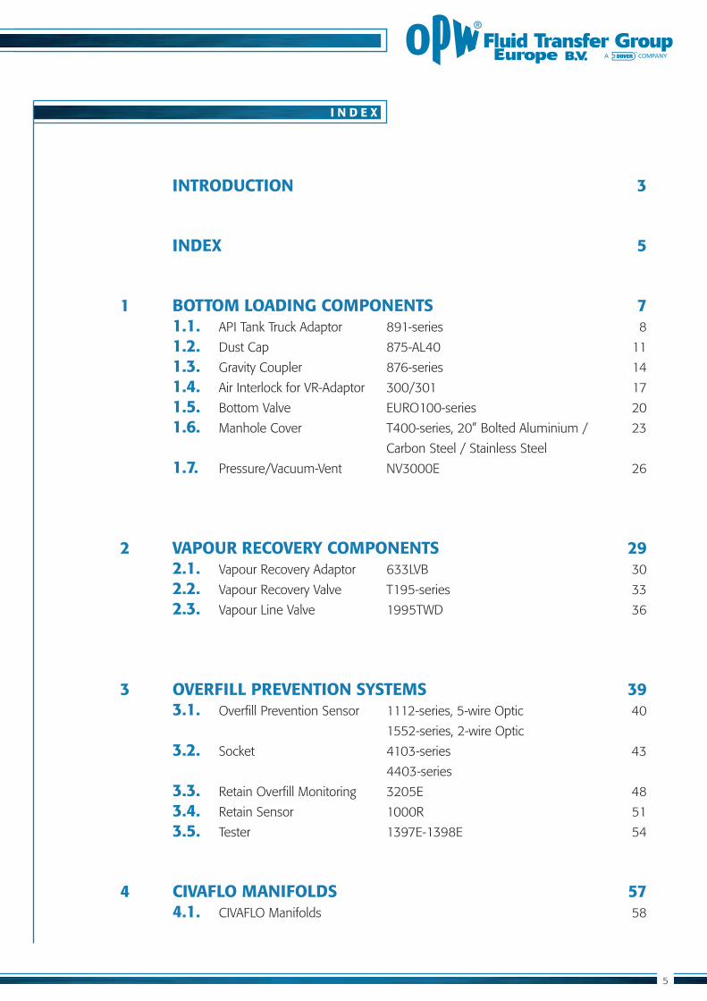
INTRODUCTION 3
INDEX 5
1 BOTTOM LOADING COMPONENTS 7 1.1. 1.2. 1.3. 1.4. 1.5. 1.6. Carbon Steel / Stainless Steel
1.7.
2 VAPOUR RECOVERY COMPONENTS 29 2.1. 2.2. 2.3.
3 OVERFILL PREVENTION SYSTEMS 39 3.1.
3.2. 4403-series
3.3. Retain Overfill Monitoring 3205E 48
3.4. 3.5.
4 CIVAFLO MANIFOLDS 57 4.1. CIVAFLO Manifolds 58
I N D E X
5
Catalog OPW.pdf 4 6-1-2012 13:16:49

Catalog OPW.pdf 5 6-1-2012 13:16:49
BO
TTOM
LOA
DIN
G CO
MPO
NEN
TS
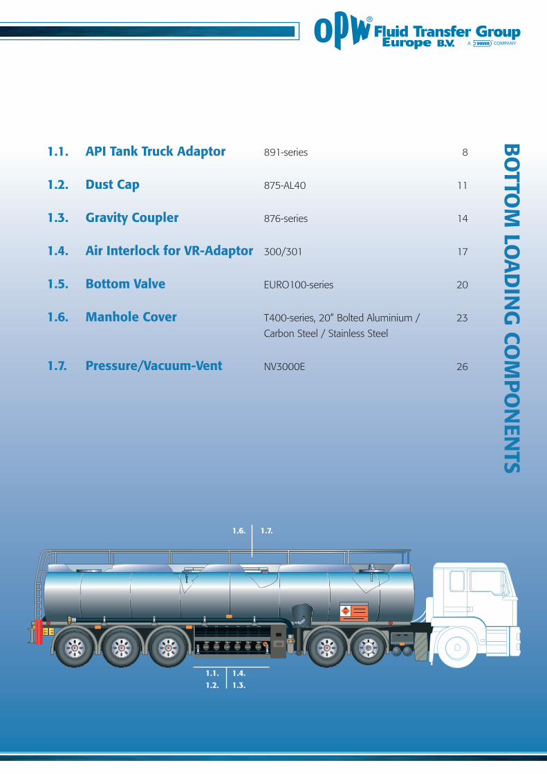
1.6.
1.4.1.3.
1.1.1.2.
1.7.
1.1. API Tank Truck Adaptor
1.2. Dust Cap
1.3. Gravity Coupler
1.4. Air Interlock for VR-Adaptor
1.5. Bottom Valve
1.6. Manhole Cover Carbon Steel / Stainless Steel
1.7. Pressure/Vacuum-Vent
Catalog OPW.pdf 6 6-1-2012 13:16:49

8
F E A T U R E S A N D B E N E F I T S
C E R T I F I C A T E S
891, EN13083
API Tank Truck Adaptor
891NB, API Adaptor
891BA, API Adaptor
Designed in accordance
Two piece
4” TTMA
Nominal size
Rotatable
Flat bottom
Minimum number of internals
Bushed running surfaces
Stainless Steel
Viton GFLT
Compatible
Heavy duty
Easy-grip
Mounting lugs
Grease nipple
891BA, API Adaptor with Air Interlock model 200
Catalog OPW.pdf 7 6-1-2012 13:16:49

S P E C I F I C A T I O N S
8 9 1 N B
8 9 1 B A
ø 11
ø 149
171
181
8 HOLES
ø 165
103
57
181
ø 197
162
214
84
51
General Spec’s API Tank Truck Adapter
Catalog OPW.pdf 8 6-1-2012 13:16:49
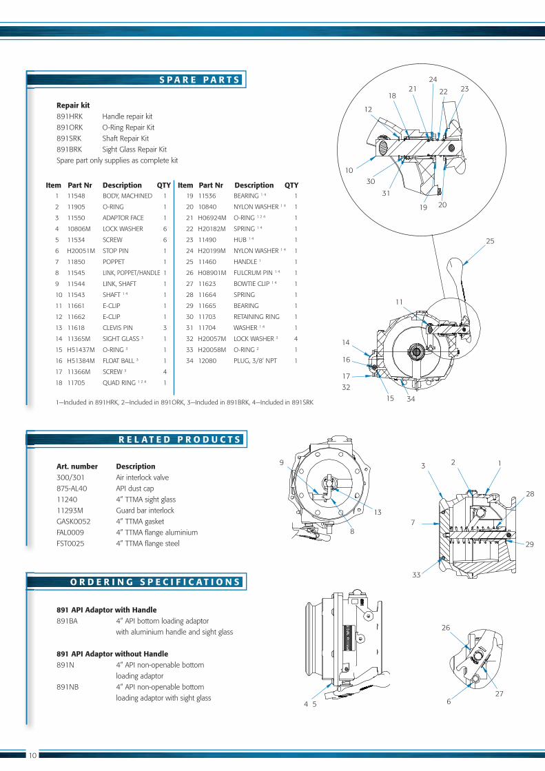
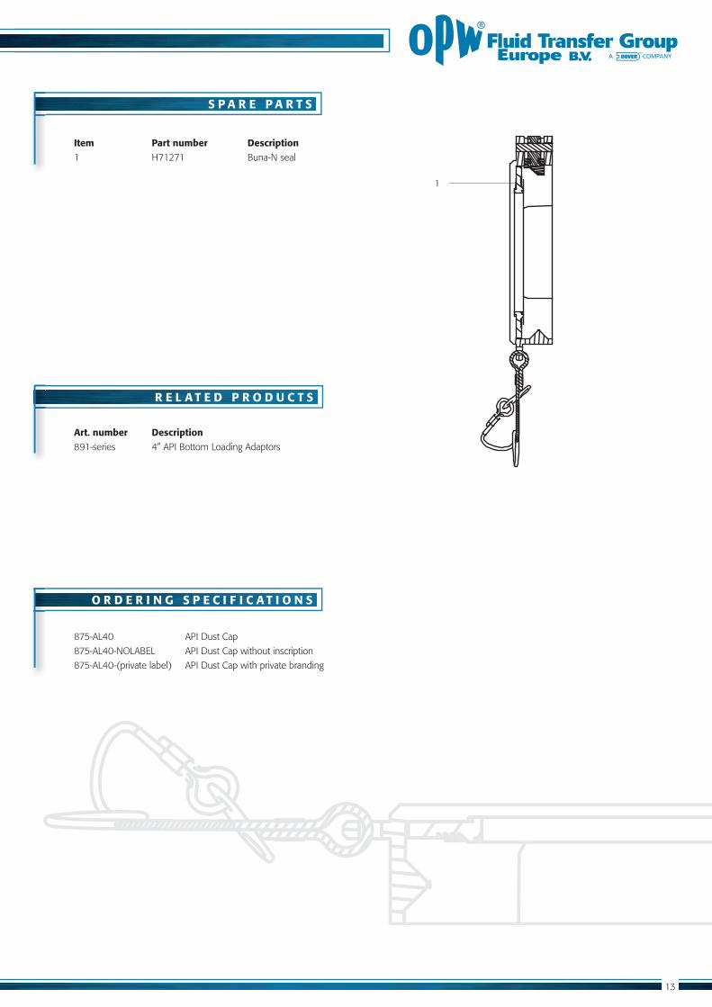
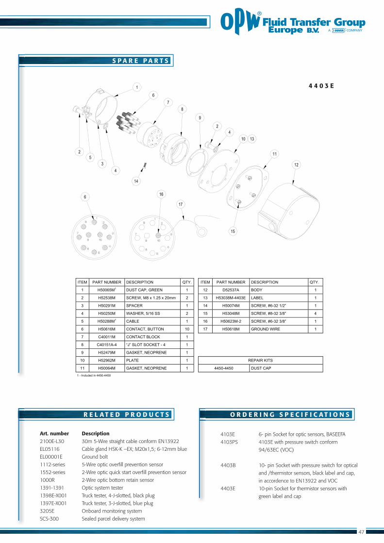
S P A R E P A R T S
R E L A T E D P R O D U C T S
O R D E R I N G S P E C I F I C A T I O N S
Repair kit
Art. number Description
891 API Adaptor with Handle
891 API Adaptor without Handle
3
33
8
Item Part Nr Description QTY Item Part Nr Description QTY
3
3
3
3
3
Catalog OPW.pdf 9 6-1-2012 13:16:51

875 AL40 Dust Cap
Certified per ADR 4.3.4.1.1 up to 3 bar
Lightweight pressure die-cast aluminium
construction for maximum strength and
weight reduction
Easy use due to radial cam and lug design
Buna-N seal
Glass-filled nylon cams to reduce wear
Locking hole for wire security seal
Private branding on API Dust Cap is optional
CIVACON’s 875 API Dust Cap is lightweight, corrosion resistant and designed for the protection of API RP 1004 tank-truck adaptors complying to ADR.
875 AL40, Dust Cap
875-AL40, ADR
F E A T U R E S A N D B E N E F I T S
C E R T I F I C A T E S
Catalog OPW.pdf 10 6-1-2012 13:16:54

S P E C I F I C A T I O N S
8 7 5 A L 4 0 D U S T C A P
General Spec’s 875-AL40 Dust Cap
Maximum working pressure 3 bar
other temperatures in request
ø130
205
All dimensions are in mm
Catalog OPW.pdf 11 6-1-2012 13:16:56
S P A R E P A R T S
R E L A T E D P R O D U C T S
O R D E R I N G S P E C I F I C A T I O N S
Item Part number Description
Art. number Description
1
Catalog OPW.pdf 12 6-1-2012 13:16:56

Gravity Coupler
Designed in accordance with API RP 1004,
ADR and EN13083
Pressure die-cast lightweight aluminium construction
for maximum strength and weight reduction
Innovative design for:
- improved high-flow rates
- minimum pressure drop
- complete draining capacities to prevent contamination
Compatible with diesel, bio diesel, gasoline,
ethanol and methanol
Viton GFLT seal
Over Centre CAM - holds on adaptor top & bottom
No wear of API adaptor surface
15° angle for improved unloading
Single piece 3” and 4” CAM and Groove
One hand operation, simple robust mechanism
The 876 Gravity Coupler optimizes the connection between 4” API Adaptors and 3” or 4” hose connections, ensuring safe and fast unloading. The 876 has been
designed with an over centre CAM for easy connection.
F E A T U R E S A N D B E N E F I T S
Catalog OPW.pdf 13 6-1-2012 13:16:56

S P E C I F I C A T I O N S
8 7 6 - S E R I E S
General Spec’s 876 Gravity Coupler
Nominal size 4” or DIN100
other temperatures in request
All dimensions are in mm
98
184
182
108
42
145
B A
129
Catalog OPW.pdf 14 6-1-2012 13:16:57
S P A R E P A R T S
R E L A T E D P R O D U C T S
O R D E R I N G S P E C I F I C A T I O N S
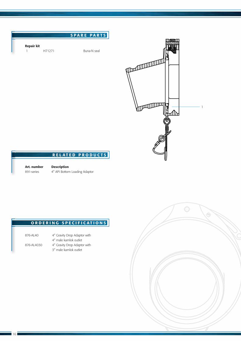
Repair kit
Art. number Description
4” male kamlok outlet
3” male kamlok outlet
1
Catalog OPW.pdf 15 6-1-2012 13:16:57
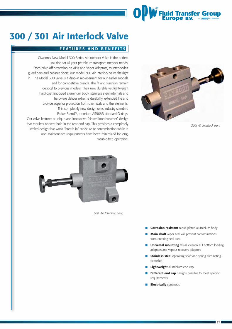
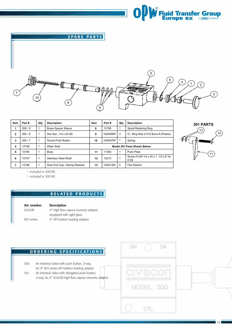
300 / 301 Air Interlock Valve
Corrosion resistant nickel-plated aluminium body
Main shaft wiper seal will prevent contaminations
from entering seal area
Universal mounting fits all civacon API bottom loading
adaptors and vapour recovery adaptors
Stainless steel operating shaft and spring eliminating
corrosion
Lightweight aluminium end cap
Different end cap designs possible to meet specific
requirements
Electrically continous
Civacon’s New Model 300 Series Air Interlock Valve is the perfect solution for all your petroleum transport interlock needs.
From drive-off protection on APIs and Vapor Adaptors, to interlocking guard bars and cabinet doors, our Model 300 Air Interlock Valve fits right in. The Model 300 valve is a drop-in replacement for our earlier models
and for competitive brands. The fit and function remain identical to previous models. Their new durable yet lightweight
hard-coat anodized aluminum body, stainless steel internals and hardware deliver extreme durability, extended life and
provide superior protection from chemicals and the elements. This completely new design uses industry standard
that requires no vent hole in the rear end cap. This provides a completely
use. Maintenance requirements have been minimized for long, trouble-free operation.
F E A T U R E S A N D B E N E F I T S
300, Air Interlock front
300, Air Interlock back
Catalog OPW.pdf 16 6-1-2012 13:16:58
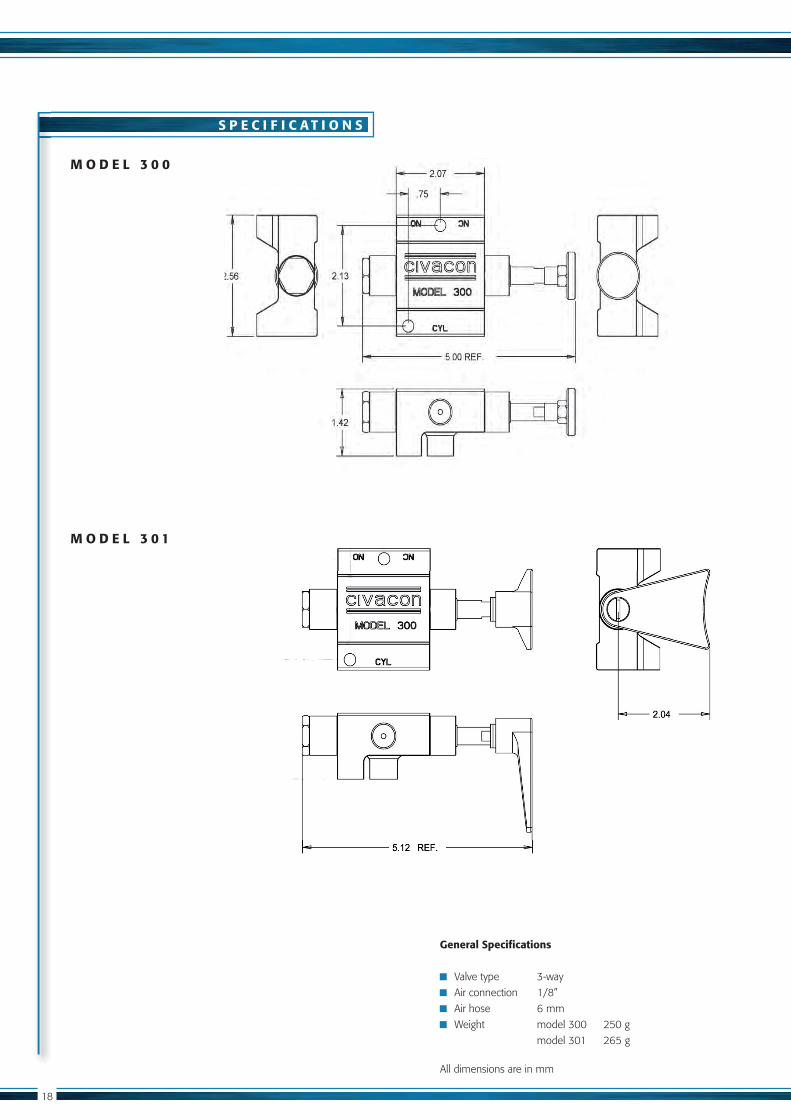
S P E C I F I C A T I O N S
M O D E L 3 0 0
M O D E L 3 0 1
General Specifications
Valve type 3-way
Weight model 300 250 g
All dimensions are in mm
Catalog OPW.pdf 17 6-1-2012 13:16:58
S P A R E P A R T S
R E L A T E D P R O D U C T S
O R D E R I N G S P E C I F I C A T I O N S
Art. number Description
equipped with sight glass
- included in 200 RK2 - included in 300 RK
300 Air Interlock Valve with push button, 3-way,
3
2 ��4 m�
��
^���
���7
��
�&�
���
���
[����@2>+�\,#�� ��",�]� ^,M�� Q#/�"�V,����� � \,#�� ��",�]� ^,M�� Q#/�"�V,����� �
1 &���@���� �� =������\���������#�� 8 �&�^^� �� �\����������?���?���
� &���@���� �� _���%*�����` ���&������ 9 _&������� �� ��@���?��b��&@��&�=*���%�Z<��!��]�
3 &���@�f� ��� ��*���<*�'�=*������ 10 _&���f�� �� �\��?��
4 �&��^�� �� ;\��������� ;�'#<�[�����",/�+=����&#<����
� �&���� ��� =���� 11 ���^��� ��� <*�'�<������
6 �&��f� ��� ����������������'�X��� ��� �&���� �� ����(�)g_h��` ���&��������`&�gj��m@m����
7 �&��m� �� �����>����\�`��\��?��������� 13 _&���&�� &� )����;��'����
2
2
2
Catalog OPW.pdf 18 6-1-2012 13:16:59

20
EURO-Line Bottom Valves
All EURO100-Line Bottom Valves in accordance
Available models:
Pressure balanced or non pressure balanced
operation
Sequenced or non-sequenced operation
4” or DN100 connection
Lightweight pressure die-cast for improved
strength and reduced weight
Hard anodized and stainless steel internals
Stainless steel filter/strainer
Shear Groove to prevent spillage in case
of an accident
Superior flow rate: - up to 2.500 litres/minute
- no moving parts in the flow path
Viton GLFT seals
Valve service inside of the compartment
Manually openable in case of emergency
EURO 100-Line, Bottom Valve Compact
EURO100-Line, Bottom Valve Super Compact
EURO100-Line, Bottom Valve 4” TTMA or TW
EURO100, EN13308 EURO100, EN13316
F E A T U R E S A N D B E N E F I T S
C E R T I F I C A T E S
Catalog OPW.pdf 19 6-1-2012 13:16:59

&����
��m
&^�
��m
|� ^
�������$
|�
|� }
��m�
��m
|��
^�|
&&&
$
�
�
�^
|�
�����%��pp��*+�
�����~���pp��*+�
Z�>�~>%���g���h>g]
|� ^
|&&
&%z
m�_�
g>��
|�
�=$
$�|��
^���
m
�
�
|���
|�
&�^
&�&
�&m
���
| }
|�f
���
&&��z
�����%��pp��*+�
�����~���pp��*+�
Z�>�~>%���g���h>g]
&&��z
S P E C I F I C A T I O N S
E U R O 1 0 0 - 3 S E R I E S
E U R O 1 0 0 - 1 S E R I E S
General Spec’s EURO100-Line Bottom Valves
Working pressure 5 bar (500 kPa)
Operating air pressure 4 bar
Maximum flow rating 2.500 litre/minute
Seals Viton GFLT
other temperatures on request
�������
|����
^�&�
�
�m�
���
|�
�mf
|&&
&��
m���
m$
|��
^�
�
�
&&��z
|�
|���
�����%��pp��*+�
�����~���pp��*+�
Z�>�~>%���g���h>g]
E U R O 1 0 0 - 2 S E R I E S
All dimensions are in mm
Catalog OPW.pdf 20 6-1-2012 13:16:59
22
S P A R E P A R T S
R E L A T E D P R O D U C T S
O R D E R I N G S P E C I F I C A T I O N S
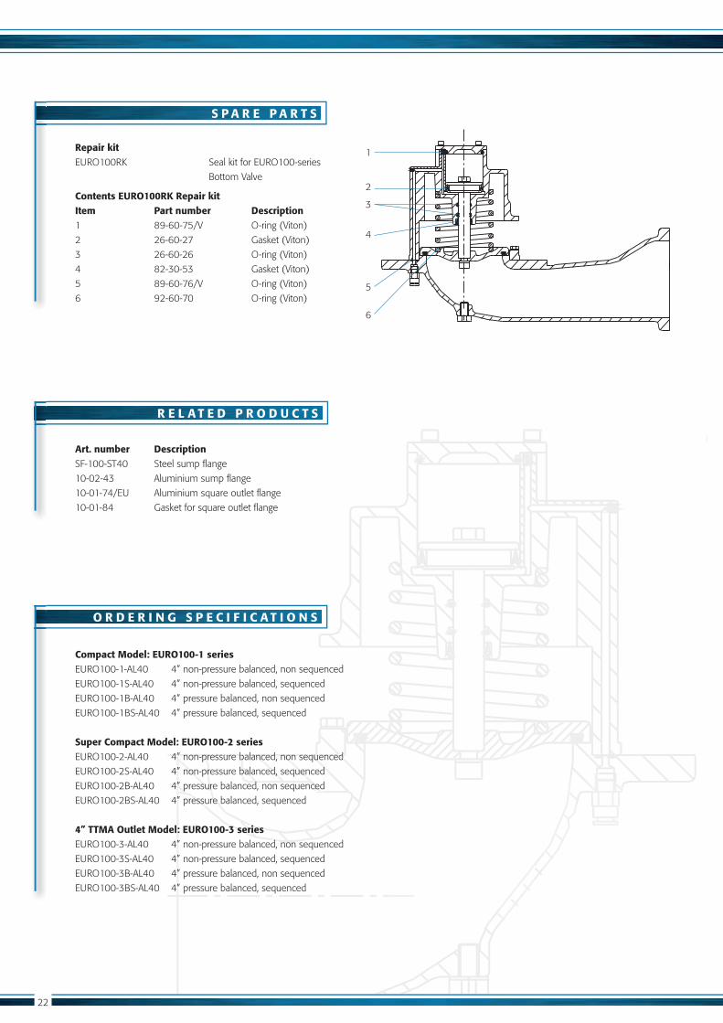
Repair kit
Bottom Valve
Contents EURO100RK Repair kitItem Part number Description
4 82-30-53 Gasket (Viton)
Art. number Description
Compact Model: EURO100-1 series
Super Compact Model: EURO100-2 series
4” TTMA Outlet Model: EURO100-3 series: -3 series
2
3
4
5
Catalog OPW.pdf 21 6-1-2012 13:17:00

23
F E A T U R E S A N D B E N E F I T S
C E R T I F I C A T E S
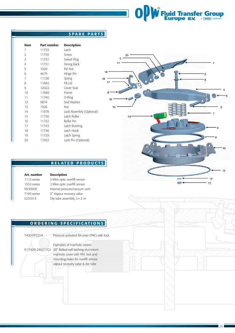
Manhole Cover T400-series
H71521, Base Plate model
T400-PFC01A, Pressure Activated Fill-cover
Complies
Pressure and vacuum vent fitted as standard for
Spring-loaded Pressure-activated fill cap
Emergency venting
Automatic sealing of the P/V vent in a roll over
situation
20” base-plate for access compliance with ADR.
Two-stage opening allows safe release of
opening fill cap.
Lockable
Secure 24-bolt fixing
Lightweight pressed aluminium base-plate
Security facility
K1-T400-240217GJ, Manhole Cover As-sembly
T400, EN13317PAF, EN13314
Catalog OPW.pdf 22 6-1-2012 13:17:00

24
S P E C I F I C A T I O N S
B A S E P L A T E E X A M P L E S
107
.070
60
THRU24 HOLESEQ. SPACED
9
THRU16 HOLESEQ. SPACED
9
THRU8 HOLES
EQ. SPACED
8
183 183
58
82.5
17022.5 °
80.0
0
109.5
0
170.
00
60.8
0
60.0
0
190
24 HOLES 9.0 - B.C=522mm
16 HOLES 9.0 - B.C.=302mm
8 HOLES 9.0 - B.C.=130mm
General Spec’s Manhole Cover T400-series
54
38
92
110140
9816
2
All dimensions are in mm
Catalog OPW.pdf 23 6-1-2012 13:17:01
25
R E L A T E D P R O D U C T S
O R D E R I N G S P E C I F I C A T I O N S
S P A R E P A R T S
mounting holes for overfill sensor,
Art. number Description
Item Part number Description
Catalog OPW.pdf 24 6-1-2012 13:17:01

Pressure Vacuum Vent
In accordance
Pressure Die-Cast aluminium design, stainless steel
and acetal components for durability and longer
life time
Automatic sealing in case of a tanker rollover
Pressure Flow capacity
Vacuum Flow capacity
Lightweight durable design (400 gram)
Removable filter for easy serviceability
Viton GFLT seals
Quick-Strip-In-place design, no tools required
Suitable for fill-covers (PAF)
Double dovetail grooves for poppet O-rings for
a more secure and longer-lasting seal
1¼ BSPP connection
CIVACON’s NV3000E high-flow pressure vacuum vent is designed for durability, safety and service performance.
NV3000E, Pressure Vacuum Vent
NV3000E, EN 14595
F E A T U R E S A N D B E N E F I T S
C E R T I F I C A T E S
Catalog OPW.pdf 25 6-1-2012 13:17:02
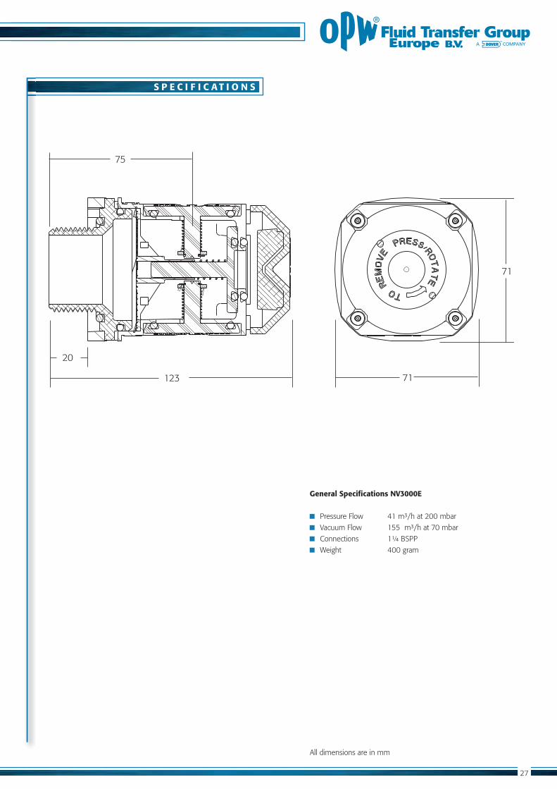
71
71
75
123
20
S P E C I F I C A T I O N S
General Specifications NV3000E
Weight 400 gram
All dimensions are in mm
Catalog OPW.pdf 26 6-1-2012 13:17:02
28
S P A R E P A R T S
R E L A T E D P R O D U C T S
O R D E R I N G S P E C I F I C A T I O N S
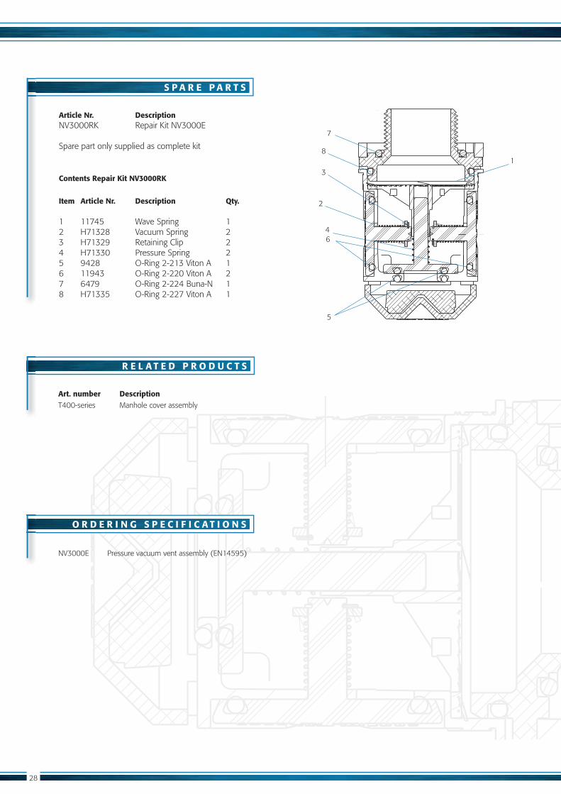
Art. number DescriptionT400-series Manhole cover assembly
5
8
4
3
2
Article Nr. Description NV3000RK Repair Kit NV3000E
Spare part only supplied as complete kit
Contents Repair Kit NV3000RK
Item Article Nr. Description Qty.
Catalog OPW.pdf 27 6-1-2012 13:17:03
VAPO
R R
ECOVERY CO
MPO
NEN
TS
2.2. 2.3.
2.1.
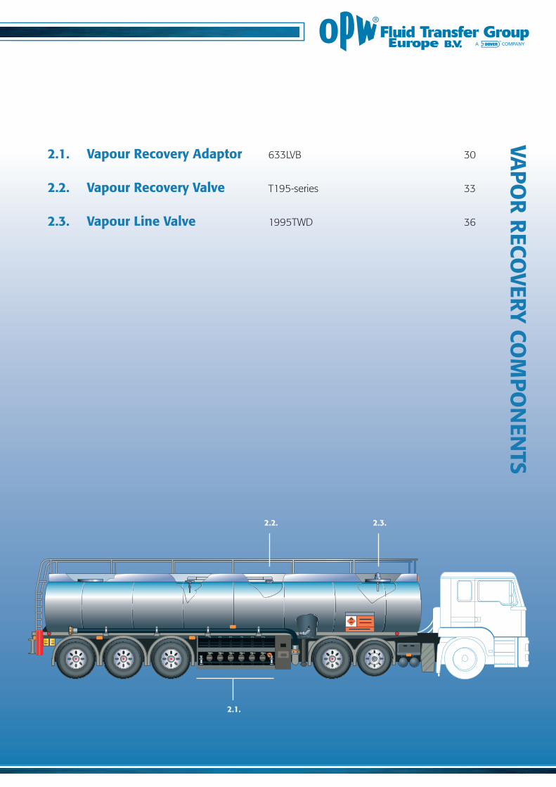
2.1. Vapour Recovery Adaptor
2.2. Vapour Recovery Valve
2.3. Vapour Line Valve
Catalog OPW.pdf 28 6-1-2012 13:17:03
30
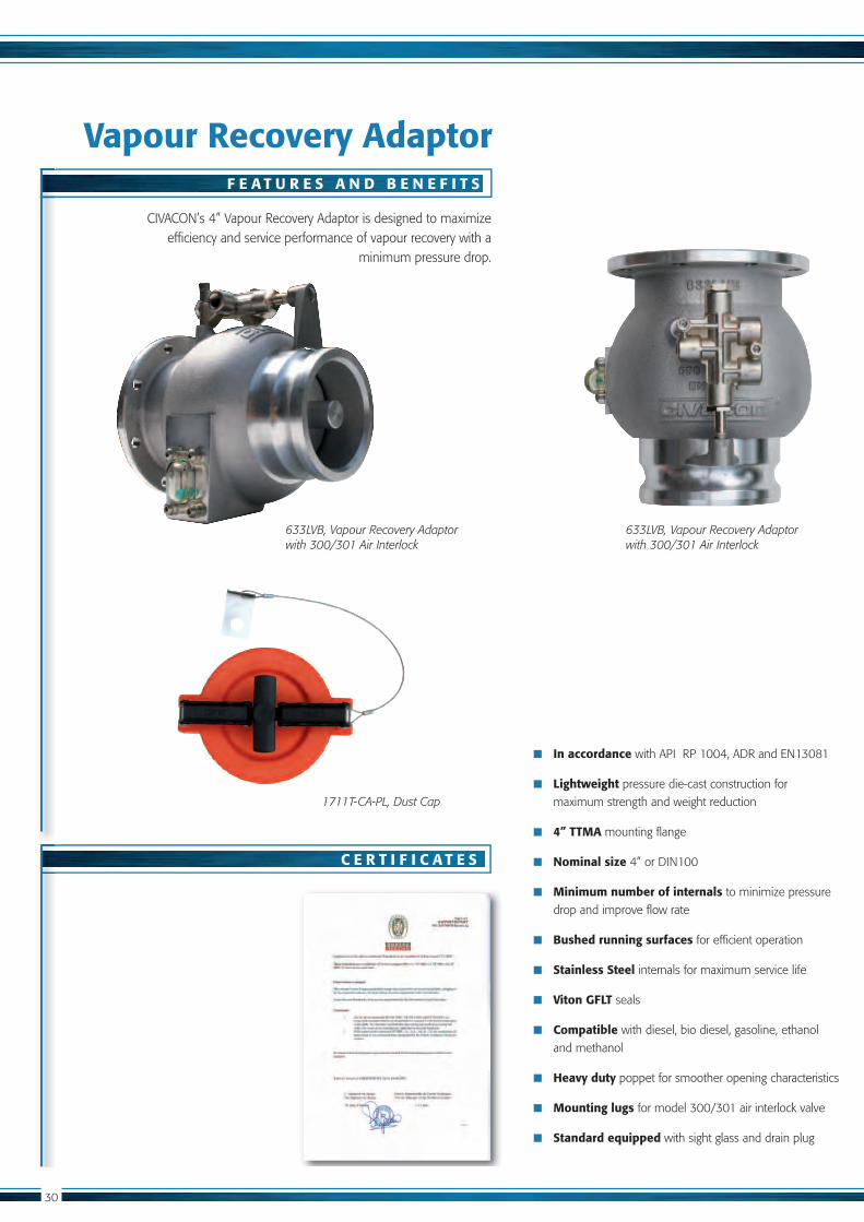
Vapour Recovery Adaptor
In accordance
Lightweight pressure die-cast construction for
maximum strength and weight reduction
4” TTMA mounting flange
Nominal size
Minimum number of internals to minimize pressure
drop and improve flow rate
Bushed running surfaces for efficient operation
Stainless Steel internals for maximum service life
Viton GFLT seals
Compatible with diesel, bio diesel, gasoline, ethanol
and methanol
Heavy duty poppet for smoother opening characteristics
Mounting lugs
Standard equipped with sight glass and drain plug
efficiency and service performance of vapour recovery with a minimum pressure drop.
633LVB, Vapour Recovery Adaptor with 300/301 Air Interlock
F E A T U R E S A N D B E N E F I T S
C E R T I F I C A T E S
1711T-CA-PL, Dust Cap
633LVB, Vapour Recovery Adaptor with 300/301 Air Interlock
Catalog OPW.pdf 29 6-1-2012 13:17:04
S P E C I F I C A T I O N S
General Specifications 633LVB-201
other temperatures in request
Weight 3,5 Kg
205
120
87
11
149
172
62
19
2754
Catalog OPW.pdf 30 6-1-2012 13:17:04

32
TM
633
LVB
S P A R E P A R T S
R E L A T E D P R O D U C T S
O R D E R I N G S P E C I F I C A T I O N S
Repair kit
Item Part Nr Description Quantity
LVH
LVH-AL
Lock Washer S.S. 4
LVH/LVB
Art. number Description
NV3000E Pressure vacuum vent
equipped with sight glass
equipped with sight glass and
4
3
2
Catalog OPW.pdf 31 6-1-2012 13:17:05
33
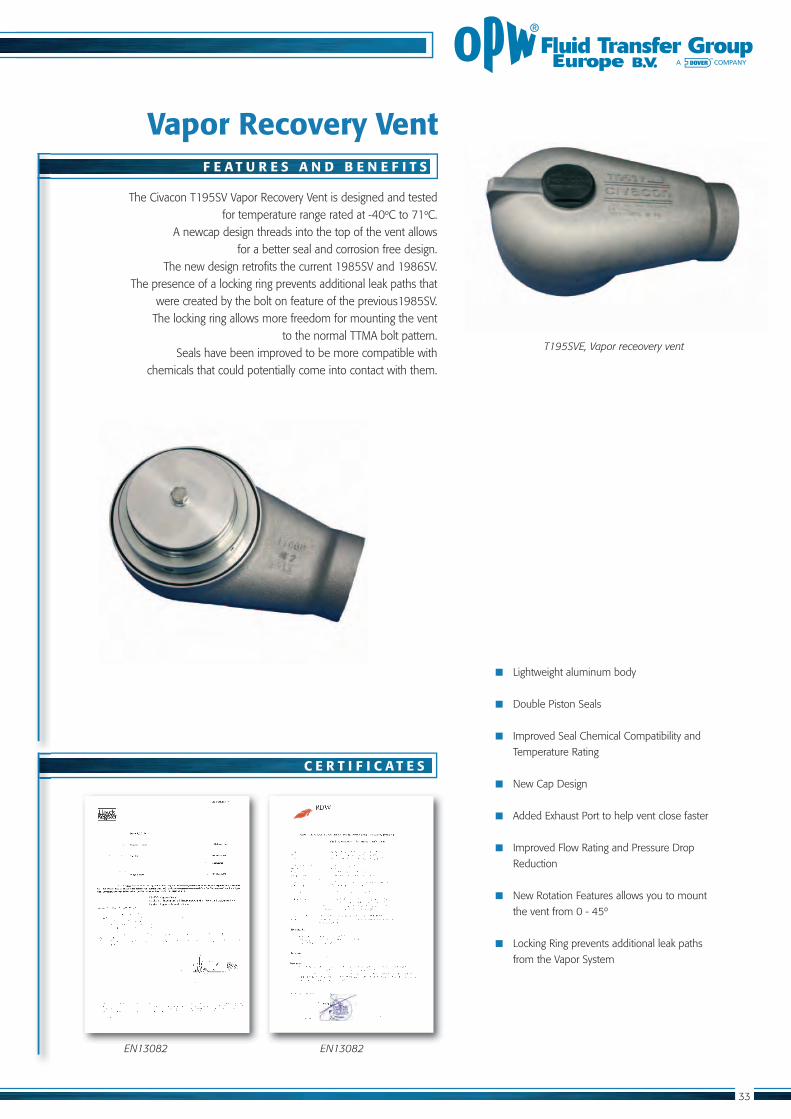
Vapor Recovery Vent
Lightweight aluminum body
Double Piston Seals
Improved Seal Chemical Compatibility and
Temperature Rating
New Cap Design
Added Exhaust Port to help vent close faster
Improved Flow Rating and Pressure Drop
Reduction
New Rotation Features allows you to mount
the vent from 0 - 45º
Locking Ring prevents additional leak paths
from the Vapor System
for temperature range rated at -40º ºC. A newcap design threads into the top of the vent allows
for a better seal and corrosion free design.
The presence of a locking ring prevents additional leak paths that
The locking ring allows more freedom for mounting the vent to the normal TTMA bolt pattern.
Seals have been improved to be more compatible with chemicals that could potentially come into contact with them.
T195SVE, Vapor receovery vent
F E A T U R E S A N D B E N E F I T S
C E R T I F I C A T E S
EN13082EN13082
Catalog OPW.pdf 32 6-1-2012 13:17:05
34
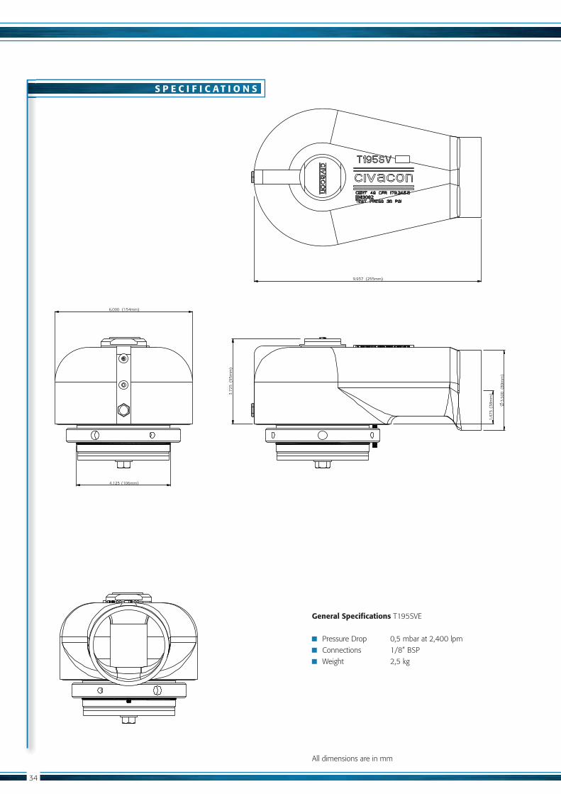
S P E C I F I C A T I O N S
General Specifications
Pressure Drop 0,5 mbar at 2,400 lpm
Weight 2,5 kg
All dimensions are in mm
(38
mm
)1.
475
(154mm)6.000
(106mm)4.125
(95
mm
)3.
725
(255mm)9.937
(89
mm
)3.
500
Catalog OPW.pdf 33 6-1-2012 13:17:06

35
S P A R E P A R T S
R E L A T E D P R O D U C T S
O R D E R I N G S P E C I F I C A T I O N S
Repair kit
Item Part Nr Description QTY.
2
Art. number Description
T400-series Manhole cover assembly
NV3000E Internal pressure/vacuum vent
2
3
4
5
8
20
FF I
Catalog OPW.pdf 34 6-1-2012 13:17:06
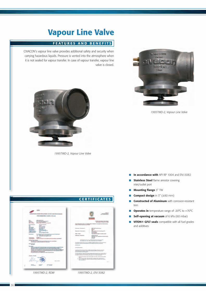
Vapour Line Valve
In accordance with
Stainless Steel flame arrestor covering
inlet/outlet port
Mounting flange
Compact design
Constructed of Aluminum with corrosion-resistant
trim
Operates in
Self-opening at vacuum
VITON® GFLT seals compatible with all fuel grades
and additives
CIVACON’s vapour line valve provides additional safety and security when carrying hazardous liquids. Pressure is vented into the atmosphere when it is not sealed for vapour transfer. In case of vapour transfer, vapour line
valve is closed.
1995TWD-2, Vapour Line Valve
1995TWD-2, EN130821995TWD-2, RDW
F E A T U R E S A N D B E N E F I T S
C E R T I F I C A T E S
1995TWD-2, Vapour Line Valve
Catalog OPW.pdf 35 6-1-2012 13:17:07
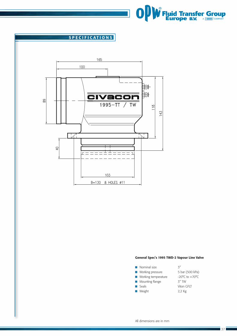
S P E C I F I C A T I O N S
General Spec’s 1995 TWD-2 Vapour Line Valve
Working pressure 5 bar (500 kPa)
Seals Viton GFLT
Weight 2,2 Kg
All dimensions are in mm
Catalog OPW.pdf 36 6-1-2012 13:17:08

38
S P A R E P A R T S
R E L A T E D P R O D U C T S
O R D E R I N G S P E C I F I C A T I O N S
Repair kit
Item Part Number Description
Spare parts only supplied as complete kit
Art. number Description
with TW-flange
with TW-flange
43
2
5
Catalog OPW.pdf 37 6-1-2012 13:17:08

OVER
FILL PR
EVENTIO
N SYSTEM
S
3.1.
3.2.3.4.
3.3.
3.1. Overfill Prevention Sensor
3.2. Socket 4403-series
3.3. Retain Overfill Monitoring 3205E 48
3.4. Retain Sensor
3.5. Tester
Catalog OPW.pdf 38 6-1-2012 13:17:09
40
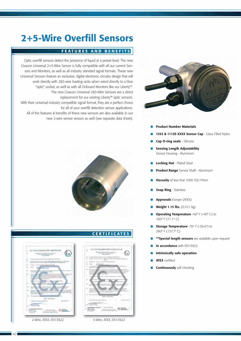
2+5-Wire Overfill Sensors
Product Number Materials
1552 & 1112E-XXXX Sensor Cap - Glass Filled Nylon
Cap O-ring seals - Silicone
Sensing Length Adjustability
Sensor Housing - Aluminum
Locking Nut - Plated Steel
Product Range Sensor Shaft - Aluminum
Viscosity
Snap Ring - Stainless
Approvals Europe (ATEX)
Weight 1.15 lbs.
Operating Temperature -40º F (-40º C) to
Storage Temperature
**Special length sensors are available upon request
In accordance
Intrinsically safe operation
ATEX certified
Continuously self checking
Optic overfill sensors detect the presence of liquid at a preset level. The new
sors and Monitors, as well as all industry standard signal formats. These new
work directly with 2&5-wire loading racks when wired directly to a blue
replacement for our existing Liberty™ optic sensors. With their universal industry compatible signal format, they are a perfect choice
for all of your overfill detection sensor applications. All of the features & benefits of these new sensors are also available in our
new 2-wire sensor version as well (see separate data sheet).
2-Wire, ATEX, EN13922 5-Wire, ATEX, EN13922
F E A T U R E S A N D B E N E F I T S
C E R T I F I C A T E S
Catalog OPW.pdf 39 6-1-2012 13:17:09
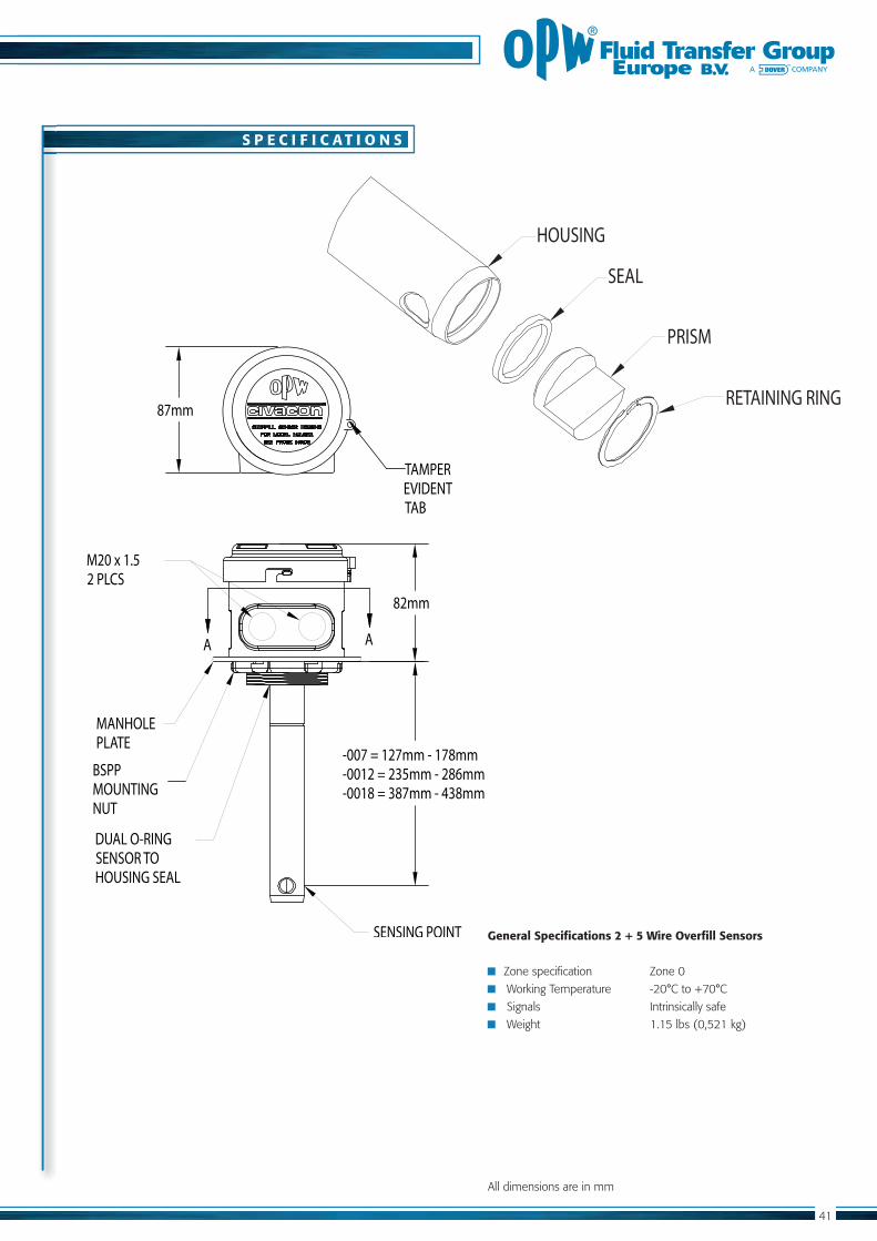
S P E C I F I C A T I O N S
General Specifications 2 + 5 Wire Overfill Sensors
Zone specification Zone 0
Signals Intrinsically safe
All dimensions are in mm
AA
82mm
87mm
BSPP MOUNTING NUT
SENSING POINT
M20 x 1.52 PLCS
TAMPER EVIDENT TAB
MANHOLE PLATE
DUAL O-RING SENSOR TO HOUSING SEAL
-007 = 127mm - 178mm-0012 = 235mm - 286mm-0018 = 387mm - 438mm
HOUSING
SEAL
PRISM
RETAINING RING
Catalog OPW.pdf 40 6-1-2012 13:17:09

42
S P A R E P A R T S
R E L A T E D P R O D U C T S
O R D E R I N G S P E C I F I C A T I O N S
Art. number Description
3205E On-board Monitoring System
SCS-300 Sealed Parcel Delivery System
Item Part Number Description QTY
1
3
4
5 H52842M
8
H52845M
H52844M O-ring
3
2
5
8
4
Catalog OPW.pdf 41 6-1-2012 13:17:10

43
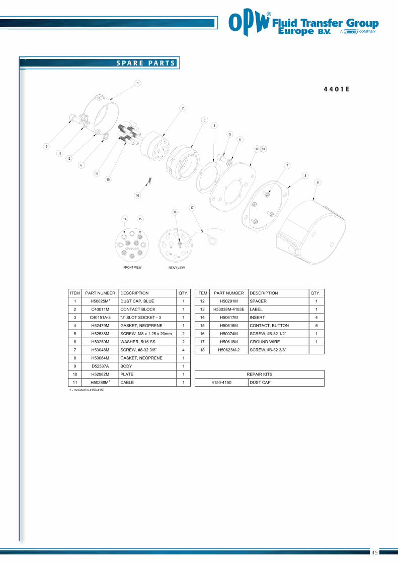
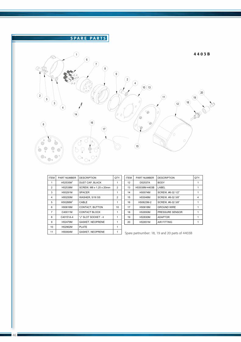
Sockets
In accordance with API standards
4403-model in accordance with
Pressure switch in accordance to VOC requirements
Simple and durable connection using 3 J-slots
Colour coded labels and caps for easy identification
Brake interlock switch
Grounding pin incorporated in all models
Connecting up to - 8 thermistor sensors
- 8 2-wire optic sensors
CIVACON’s Sockets are designed for optimal communication between
4103E Socket
EN13922 Conformation declaration
F E A T U R E S A N D B E N E F I T S
C E R T I F I C A T E S
4403E Socket 4403B Socket
Catalog OPW.pdf 42 6-1-2012 13:17:10

44
S P E C I F I C A T I O N S
4 1 0 3 E
General Spec’s 4103 & 4403 Sockets
All dimensions are in mm
4 4 0 3 E
4103E
WW
W. OP W- F T G . NL ( + 3 1 ) 2 5 2 - 6 6 0
3
00
FLUID TRANSFER GROUP COMPANYAN
YFLUID TRANSFER GROUP COMPANYAN
4403E
WW
W
. OP W- F T G . NL ( + 3 1 ) 2 5 2 - 6 6 03
00
Catalog OPW.pdf 43 6-1-2012 13:17:11
45
S P A R E P A R T S
PAR
TS B
REA
K D
OW
N
��>�� <����%~�=>�� h>���<���%� ���$� ��>�� <����%~�=>�� h>���<���%� ���$�
�� _���&���� h~����<��=g~>� �� �&� _��&^��� �<�>�� ��
&� ������ �%����=g��� �� ��� _����m�@ ���>� g�=>g� ��
�� �����@�� q�w��g������>��@��� �� � � _����f�� �%�>��� �
� _�& f^�� j���>���%>�<�>%>� �� ��� _������� �%�����=~���%� ��
�� _�&��m�� ��>;���m����$&����&�pp� &� ��� _���f �� ��>;����@�&��`&w� ��
�� _��&���� ;��_>����`������ &� �f� _����m�� j��~%h�;��>� ��
f� _��� m�� ��>;���m@�&��`mw� � �m� _���&��@&� ��>;����@�&��`mw� �
m� _���� �� j���>���%>�<�>%>� ��
^� h�&��f�� =�h�� ��
��� _�&^�&�� <g��>� �� �><���������
��� _��&mm��� �=g>� �� ���@ ����
��@�����*������ ���@ ����
h~����<�
4 4 0 1 E
Catalog OPW.pdf 44 6-1-2012 13:17:11
S P A R E P A R T S
�@2
>+�&
2�@
X�Q
�U
��
��>�� <����%~�=>�� h>���<���%� ���$� ��>�� <����%~�=>�� h>���<���%� ���$�
�� _�&������ h~����<��=g��� �� �&� h�&��f�� =�h�� ��
&� _�&��m�� ��>;���m����$&����&�pp� &� ��� _����m�@ ��=� g�=>g� ��
�� _��&^��� �<�>�� �� � � _���f �� ��>;����@�&��`&w� ��
� _��&���� ;��_>����`������ &� ��� _��� m�� ��>;���m@�&��`mw� �
�� _��&mm��� �=g>� �� ��� _���&��@&� ��>;����@�&��`mw� ��
�� _������� �%�����=~���%� ��� �f� _����m�� j��~%h�;��>� ��
f� ������ �%����=g��� �� �m� _�&����� <�>��~�>��>%���� ��
m� �����@ � q�w��g������>��@� � �� �^� _�&m���� �h�<���� ��
^� _�& f^�� j���>���%>�<�>%>� �� &��
��� _�&^�&�� <g��>� ��
��� _���� �� j���>���%>�<�>%>� ��
_�&����� ����)����%j� ��
4 4 0 3 B
Catalog OPW.pdf 45 6-1-2012 13:17:11
S P A R E P A R T S
R E L A T E D P R O D U C T S O R D E R I N G S P E C I F I C A T I O N S
Art. number Description
3205E Onboard monitoring system
SCS-300 Sealed parcel delivery system
and /thermistor sensors, black label and cap,
green label and cap
�@2
>+�&
2�@
X�Q
�U
��
��>�� <����%~�=>�� h>���<���%� ���$� ��>�� <����%~�=>�� h>���<���%� ���$�
�� _�������� h~����<��j�>>%� �� �&� h�&��f�� =�h�� ��
&� _�&��m�� ��>;���m����$&����&�pp� &� ��� _����m�@ ��>� g�=>g� ��
�� _��&^��� �<�>�� �� � � _���f �� ��>;����@�&��`&w� ��
� _��&���� ;��_>����`������ &� ��� _��� m�� ��>;���m@�&��`mw� �
�� _��&mm��� �=g>� �� ��� _���&��@&� ��>;����@�&��`mw� ��
�� _������� �%�����=~���%� ��� �f� _����m�� j��~%h�;��>� ��
f� ������ �%����=g��� ��
m� �����@ � q�w��g������>��@� � ��
^� _�& f^�� j���>���%>�<�>%>� ��
��� _�&^�&�� <g��>� ��
��� _���� �� j���>���%>�<�>%>� �� ��@ ��� h~����<�
��@�����*������ ��@ ���
�><���������
4 4 0 3 E
Catalog OPW.pdf 46 6-1-2012 13:17:12
48
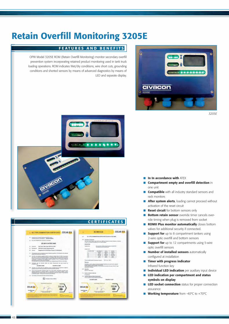
Retain Overfill Monitoring 3205E
OPW Model 3205E ROM (Retain Overfill Monitoring) monitor secondary overfill
prevention system incorporating retained product monitoring used in tank truck
loading operations. ROM indicates Wet/dry conditions, wire short cuts, grounding
conditions and shorted sensors by means of advanced diagnostics by means of
LED and separate display.
F E A T U R E S A N D B E N E F I T S
C E R T I F I C A T E S
In In accordance with ATEX
Compartment empty and overfill detection in
one unit
Compatible with all industry standard sensors and
rack monitors
After system alerts, loading cannot proceed without
activation of the reset circuit
Reset circuit for bottom sensors only
Bottom retain sensor override timer cancels over-
ride timing when plug is removed from socket
ROMII Plus monitor automatically closes bottom
valves for additional security if connected.
Support for up to 8 compartment tankers using
2-wire optic overfill and bottom sensors
Support for optic overfill sensors
Number of installed sensors automatically
configured at installation
Timer with progress indicator Infrared function key
Individual LED indication per auxiliary input device
LED indication per compartment and status symbols on display
LED socket connection status for proper connection
assurance
Working temperature
3205E
Catalog OPW.pdf 47 6-1-2012 13:17:13

230
150
S P E C I F I C A T I O N S
General Spec’s ROMII Plus Onboard Monitoring System
Power 24 VDC
Weight 2,2 Kg
All dimensions are in mm
40
Catalog OPW.pdf 48 6-1-2012 13:17:13

50
214
134
n6.
5
R E L A T E D P R O D U C T S
O R D E R I N G S P E C I F I C A T I O N S
Art. number Description
3205E ROM onboard monitoring system
Catalog OPW.pdf 49 6-1-2012 13:17:14
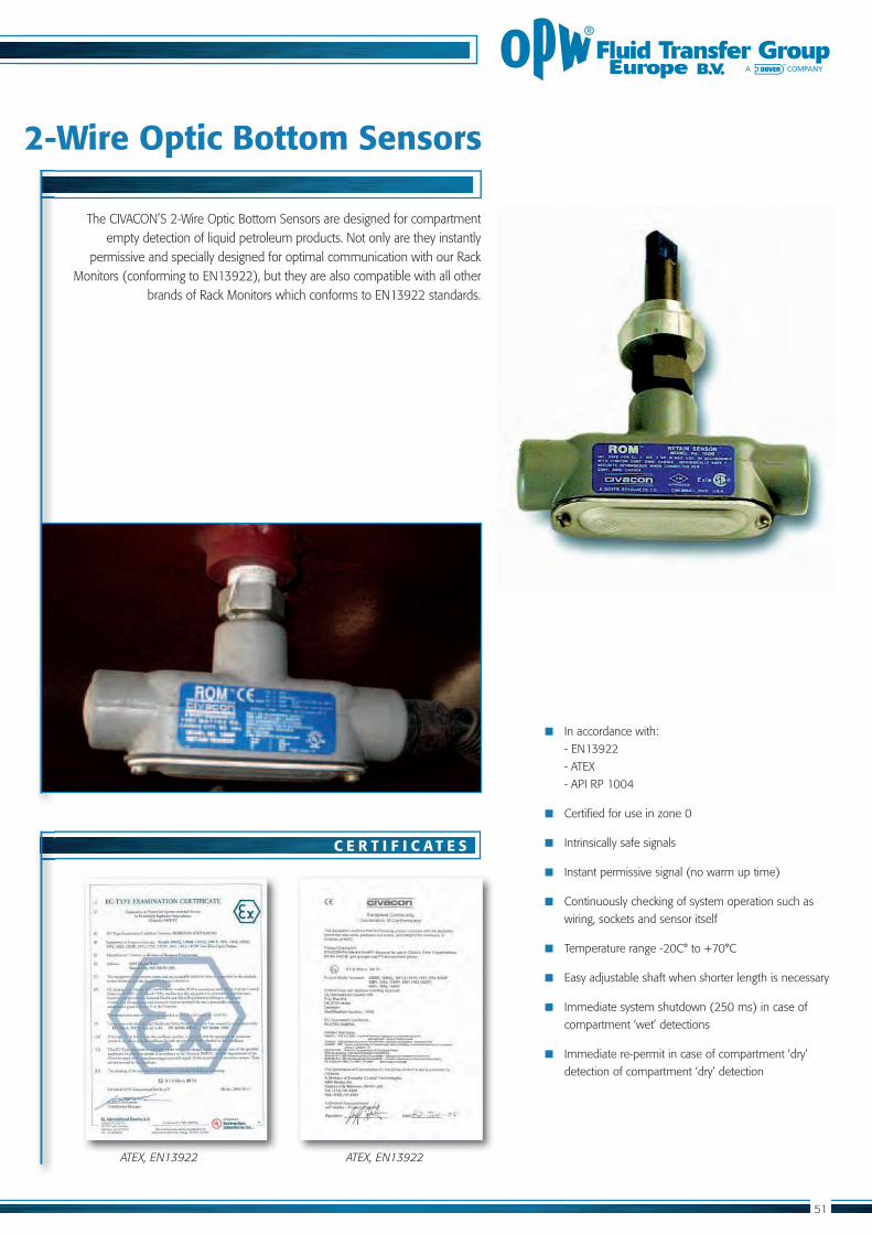
2-Wire Optic Bottom Sensors
In accordance with:
- ATEX
Certified for use in zone 0
Intrinsically safe signals
Instant permissive signal (no warm up time)
Continuously checking of system operation such as
wiring, sockets and sensor itself
Immediate system shutdown (250 ms) in case of
compartment ‘wet’ detections
Immediate re-permit in case of compartment ‘dry’
detection of compartment ‘dry’ detection
The CIVACON’S 2-Wire Optic Bottom Sensors are designed for compartment empty detection of liquid petroleum products. Not only are they instantly
permissive and specially designed for optimal communication with our Rack
ATEX, EN13922 ATEX, EN13922
C E R T I F I C A T E S
Catalog OPW.pdf 50 6-1-2012 13:17:15

52
S P E C I F I C A T I O N S
General Spec’s Bottom Sensor
Zone specification Zone 0
Signals Intrinsically safe
Weight 320 g
All dimensions are in mm
130
27
65
130
33
1000R
Catalog OPW.pdf 51 6-1-2012 13:17:15
53
R E L A T E D P R O D U C T S
O R D E R I N G S P E C I F I C A T I O N S
Art. number Description
3205E On-board Monitoring System
SCS-300 Sealed Parcel Delivery System
with bottom inline housing
Catalog OPW.pdf 52 6-1-2012 13:17:16
54
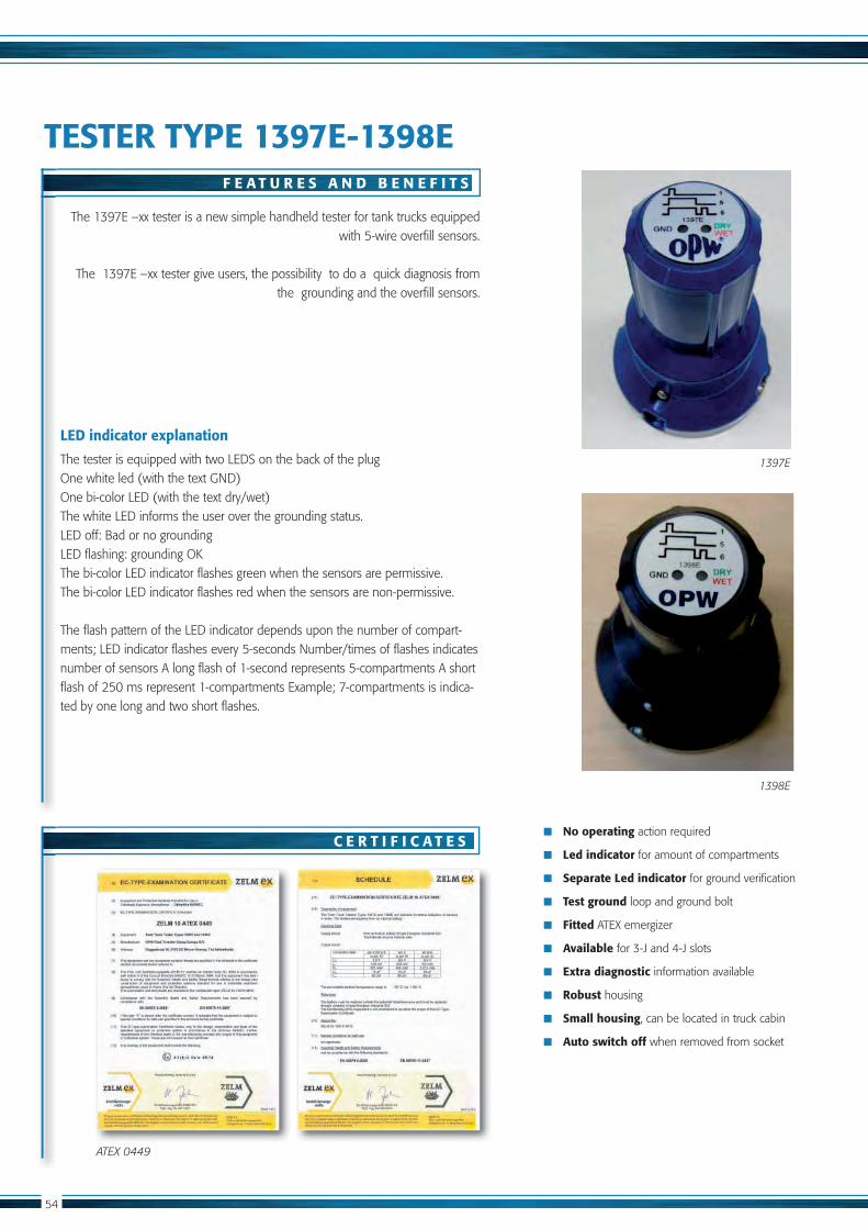
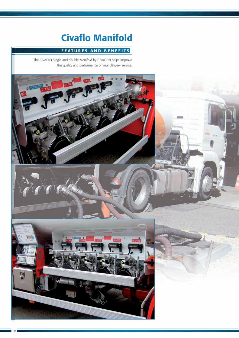
TESTER TYPE 1397E-1398E
No operating action required
Led indicator for amount of compartments
Separate Led indicator for ground verification
Test ground loop and ground bolt
Fitted ATEX emergizer
Available for 3-J and 4-J slots
Extra diagnostic information available
Robust housing
Small housing, can be located in truck cabin
Auto switch off when removed from socket
with 5-wire overfill sensors.
the grounding and the overfill sensors.
LED indicator explanation
The tester is equipped with two LEDS on the back of the plugOne white led (with the text GND) One bi-color LED (with the text dry/wet)The white LED informs the user over the grounding status.LED off: Bad or no groundingLED flashing: grounding OKThe bi-color LED indicator flashes green when the sensors are permissive.The bi-color LED indicator flashes red when the sensors are non-permissive.
The flash pattern of the LED indicator depends upon the number of compart-ments; LED indicator flashes every 5-seconds Number/times of flashes indicates
ted by one long and two short flashes.
ATEX 0449
F E A T U R E S A N D B E N E F I T S
C E R T I F I C A T E S
1397E
1398E
Catalog OPW.pdf 53 6-1-2012 13:17:16

55
S P E C I F I C A T I O N S
1 3 9 7 E / 1 3 9 8 E
R E L A T E D P R O D U C T S
O R D E R I N G S P E C I F I C A T I O N S
Art. number Description
ROMII-Plus Onboard monitoring system
SCS-300 Sealed parcel delivery system
143
OPW
156
GND DRYWET
1398E
n 98
Catalog OPW.pdf 54 6-1-2012 13:17:17

Catalog OPW.pdf 55 6-1-2012 13:17:17

CIVAFLO
MA
NIFO
LD SYSTEM
S
4.1.
4.1. CIVAFLO Manifolds 58
Catalog OPW.pdf 56 6-1-2012 13:17:18
58
F E A T U R E S A N D B E N E F I T S
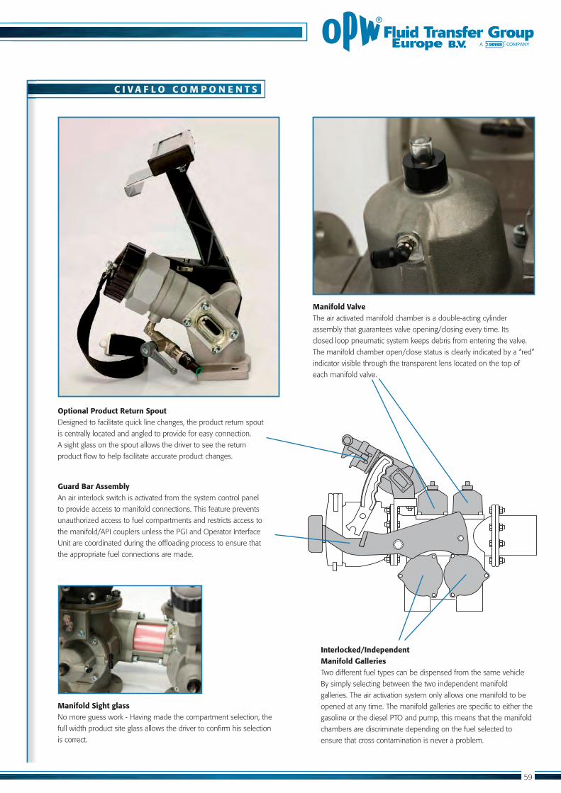
The CIVAFLO Single and double Manifold by CIVACON helps improve the quality and performance of your delivery service.
Civaflo Manifold
Catalog OPW.pdf 57 6-1-2012 13:17:18
C I V A F L O C O M P O N E N T S
Optional Product Return SpoutDesigned to facilitate quick line changes, the product return spout
is centrally located and angled to provide for easy connection.
A sight glass on the spout allows the driver to see the return
product flow to help facilitate accurate product changes.
Guard Bar AssemblyAn air interlock switch is activated from the system control panel
to provide access to manifold connections. This feature prevents
unauthorized access to fuel compartments and restricts access to
the manifold/API couplers unless the PGI and Operator Interface
the appropriate fuel connections are made.
Manifold ValveThe air activated manifold chamber is a double-acting cylinder
assembly that guarantees valve opening/closing every time. Its
closed loop pneumatic system keeps debris from entering the valve.
indicator visible through the transparent lens located on the top of
each manifold valve.
Interlocked/IndependentManifold GalleriesTwo different fuel types can be dispensed from the same vehicle
By simply selecting between the two independent manifold
galleries. The air activation system only allows one manifold to be
opened at any time. The manifold galleries are specific to either the
gasoline or the diesel PTO and pump, this means that the manifold
chambers are discriminate depending on the fuel selected to
ensure that cross contamination is never a problem.
Manifold Sight glassNo more guess work - Having made the compartment selection, the
full width product site glass allows the driver to confirm his selection
is correct.
Catalog OPW.pdf 58 6-1-2012 13:17:19
4
5
M A N I F O L D O P E R A T I O N
Bottom LoadingThe guard bar is released to provide access to the API coupler.
Both manifold valves remain closed providing for high,
unobstructed flow rates.
Pump Unloading – Manifold and Valve OperationDuring pump unloading, the appropriate manifold and valve is selected to allow the flow of fuel into the collection
tubes, through the pump and then dispensed through the meter and hose.
Product ReturnAn interlock switch that receives a signal from the operator interface
unit and main control unit releases the guard bar. A tight-fill nozzle
is connected to the return spout to allow for the return of fuel left
in the hose to the appropriate fuel compartment. A sight glass on
the spout allows the driver to see the return product flow to help
facilitate accurate product changes.
Diesel
Gas Air Closed
Diese l Air Open
Diesel to Pump
Gas
Gas Air Open
Diese l Air Closed
Gas to Pump
Product Return Sight Glass for Visual Confirmation of Change
Fit Hose Nozzle
Product Returning to Compartment
The Civaflo dual manifold provides a wide range of options depending on your particular loading or unloading arrangement:
Catalog OPW.pdf 59 6-1-2012 13:17:19

N O T E S
Catalog OPW.pdf 60 6-1-2012 13:17:20

N O T E S
Catalog OPW.pdf 61 6-1-2012 13:17:20
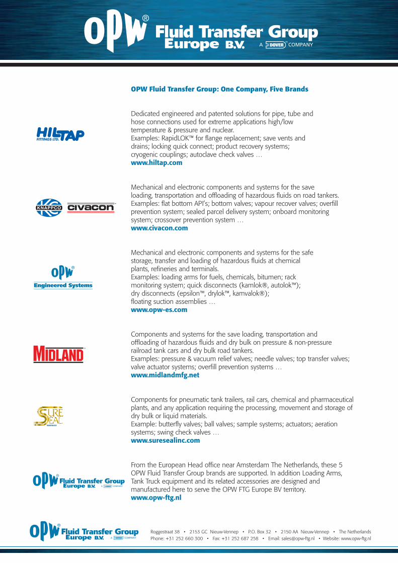
OPW Fluid Transfer Group: One Company, Five Brands
www.hiltap.com
www.civacon.com
www.opw-es.com
www.midlandmfg.net
www.suresealinc.com
www.opw-ftg.nl
Catalog OPW.pdf 62 6-1-2012 13:17:20