Embed Size (px)
Citation preview

Instruction Manual106-300NFX Rev. 4.2January 2002
http://www.processanalytic.com
World Class 3000Oxygen Analyzer (CENELEC)with IFT 3000 Intelligent FieldTransmitter (CENELEC)

Emerson Process ManagementRosemount Analytical Inc.Process Analytic Division1201 N. Main St.Orrville, OH 44667-0901T (330) 682-9010F (330) 684-4434e-mail: [email protected]://www.processanalytic.com
ESSENTIAL INSTRUCTIONSREAD THIS PAGE BEFORE PROCEEDING!
Rosemount Analytical designs, manufactures and tests its products to meet many national andinternational standards. Because these instruments are sophisticated technical products, youMUST properly install, use, and maintain them to ensure they continue to operate within theirnormal specifications. The following instructions MUST be adhered to and integrated into yoursafety program when installing, using, and maintaining Rosemount Analytical products. Failure tofollow the proper instructions may cause any one of the following situations to occur: Loss of life;personal injury; property damage; damage to this instrument; and warranty invalidation.
• Read all instructions prior to installing, operating, and servicing the product.
• If you do not understand any of the instructions, contact your Rosemount Analytical repre-sentative for clarification.
• Follow all warnings, cautions, and instructions marked on and supplied with the product.
• Inform and educate your personnel in the proper installation, operation, and mainte-nance of the product.
• Install your equipment as specified in the Installation Instructions of the appropriate In-struction Manual and per applicable local and national codes. Connect all products to theproper electrical and pressure sources.
• To ensure proper performance, use qualified personnel to install, operate, update, program,and maintain the product.
• When replacement parts are required, ensure that qualified people use replacement partsspecified by Rosemount. Unauthorized parts and procedures can affect the product’s per-formance, place the safe operation of your process at risk, and VOID YOUR WARRANTY.Look-alike substitutions may result in fire, electrical hazards, or improper operation.
• Ensure that all equipment doors are closed and protective covers are in place, exceptwhen maintenance is being performed by qualified persons, to prevent electrical shockand personal injury.
The information contained in this document is subject to change without notice.

HIGHLIGHTS OF CHANGES
Effective June, 1997 Rev. 4
Page Summary
--- General. Added snubber version of probe to manual. Text and artchanged as necessary to reflect new style of probe.
Effective February, 1998 Rev. 4.1
Page Summary
Page 2-2 Figure 2-1. Change calibration gas tube dimensions.
Page 3-10 Add note on test gas flowmeter.
Effective January, 2002 Rev. 4.2
Page Summary
Page 2-13 Updated Figure 2-8.
Page 2-14 Updated analog output current/voltage mode selection procedure.

HIGHLIGHTS OF CHANGESAPPENDIX AX
Effective June, 1997 Rev. 2
Page Summary
-- General. Added snubber version of probe to manual. Text and artchanged as necessary to reflect new style probe.
Effective February, 1998 Rev. 2.1
Page Summary
Page A-12 Changed screw torque in paragraph A-3h.

HIGHLIGHTS OF CHANGESAPPENDIX BX
Effective February, 1995 Rev. 1.1
Page Summary
B-3 Figure B-3. Updated for IB consistency.
Effective January, 1997 Rev. 1.2
Page Summary
Page B-2 Figure B-2. Added fuse locations.
Page B-5 Insert protective cover and ground lead warning.
Page B-8 Insert protective cover and ground lead warning.
Page B-11 Table B-2. Add expanded fuse specifications to replacement parts.

HIGHLIGHTS OF CHANGESAPPENDIX DX
Effective February, 1995 Rev. 2
Page Summary
-- General. Updated appendix with new version of MPS.
Effective January, 1997 Rev. 2.1
Page Summary
Page D-5 Insert protective cover and ground lead warning.
Page D-7 Insert protective cover and ground lead warning. Add fusespecifications and clarify fuse replacement.
Page D-11 Add fuse specifications to replacement parts

HIGHLIGHTS OF CHANGESAPPENDIX EX
Effective February, 1995 Rev. 1.1
Page Summary
Page E-4 Figure E-2. Updated for IB consistency.
Page E-7 Figure E-4. Updated Flowchart.
Effective May, 1995 Rev. 1.2
Page Summary
Page E-4 Figure E-2. Added callout text Heater Power Supply (Optional).
Effective January, 1997 Rev. 1.3
Page Summary
Page E-5 Insert protective cover and ground lead warning.
Page E-9 Insert protective cover and ground lead warning.
Page E-15 Added expanded fuse specifications to replacement parts

HIGHLIGHTS OF CHANGESAPPENDIX JX
Effective January, 1997 Rev. 1.0
Page Summary
Page J-4 Insert warning concerning protective equipment covers and safetyground leads.
Page J-11 Insert warning concerning protective equipment covers and safetyground leads.

Instruction Manual106-300NFX Rev. 4.2
January 2002
Rosemount Analytical Inc. A Division of Emerson Process Management i
World Class 3000
TABLE OF CONTENTS
PREFACE......................................................................................................................... P1Definitions ......................................................................................................................... P1Safety Instructions ........................................................................................................... P2
1-0 DESCRIPTION ................................................................................................................ 1-11-1 Component Checklist Of Typical System (Package Contents) ....................................... 1-11-2 System Overview............................................................................................................. 1-1
2-0 INSTALLATION .............................................................................................................. 2-12-1 Oxygen Analyzer (Probe) Installation.............................................................................. 2-12-2 Intelligent Field Transmitter (IFT) Installation .................................................................. 2-92-3 Heater Power Supply Installation .................................................................................. 2-162-4 Multiprobe Test Gas Sequencer Installation ................................................................. 2-20
3-0 SETUP AND OPERATION ........................................................................................... 3-13-1 Overview.......................................................................................................................... 3-13-2 IFT with GUI and LDP Front Panel Controls and Indicators ........................................... 3-23-3 Help Key .......................................................................................................................... 3-23-4 Status Line....................................................................................................................... 3-33-5 Quick Reference Chart .................................................................................................... 3-33-6 Main Menu ....................................................................................................................... 3-33-7 Probe Data Sub-Menu.................................................................................................... 3-63-8 Calibrate O2 ub-Menu..................................................................................................... 3-63-9 Setup Sub-Menu.............................................................................................................. 3-63-10 System Calibration........................................................................................................... 3-9
4-0 LDP OPERATION .......................................................................................................... 4-14-1 Overview.......................................................................................................................... 4-14-2 IFT with LDP Front Panel Controls and Indicators .......................................................... 4-14-3 LDP Displays ................................................................................................................... 4-14-4 LDP Defaults.................................................................................................................... 4-24-5 Calibration........................................................................................................................ 4-2
5-0 TROUBLESHOOTING.................................................................................................... 5-15-1 Overview.......................................................................................................................... 5-15-2 Special Troubleshooting Notes........................................................................................ 5-15-3 System Troubleshooting.................................................................................................. 5-2
6-0 RETURN OF MATERIAL .............................................................................................. 6-1
7-0 APPENDICES ................................................................................................................. 7-1
8-0 INDEX.............................................................................................................................. 8-1
9-0 DRAWINGS AND SCHEMATICS................................................................................. 9-1

Instruction Manual106-300NFX Rev. 4.2January 2002
ii Rosemount Analytical Inc. A Division of Emerson Process Management
World Class 3000
LIST OF ILLUSTRATIONS
Figure 1-1. Typical System Package ....................................................................................... 1-1Figure 1-2. Typical System Installation .................................................................................... 1-5Figure 1-3. World Class 3000 Typical Application with Intelligent Field Transmitters -
CENELEC Approved ............................................................................................. 1-6Figure 2-1. Probe Installation ................................................................................................... 2-2Figure 2-2. Orienting the Optional Vee Deflector ..................................................................... 2-7Figure 2-3. Air set, Plant Air Connection.................................................................................. 2-8Figure 2-4. Outline of Intelligent Field Transmitter ................................................................... 2-9Figure 2-5. Power Supply Board Jumper Configuration ........................................................ 2-10Figure 2-6. IFT Power Supply Board Jumpers....................................................................... 2-11Figure 2-7. Wiring Layout for IFT 3000 (CENELEC approved) System without HPS............ 2-12Figure 2-8. IFT Microprocessor Board Jumper Configuration................................................ 2-13Figure 2-9. IFT Microprocessor Board Jumpers .................................................................... 2-14Figure 2-10. Interconnect Board Jumper Configuration........................................................... 2-14Figure 2-11. IFT Interconnect Board Output Connections ....................................................... 2-15Figure 2-12. Outline of CENELEC Approved Heater Power Supply........................................ 2-16Figure 2-13. Wiring layout for IFT 3000 (CENELEC approved) with HPS............................... 2-17Figure 2-14. CENELEC Approved Heater Power Supply Wiring Connections........................ 2-19Figure 2-15. Jumper Selection Label. ...................................................................................... 2-19Figure 2-16. Jumpers on HPS Motherboard ............................................................................ 2-20Figure 2-17. MPS Module ........................................................................................................ 2-21Figure 2-18. MPS Gas Connections ........................................................................................ 2-22Figure 2-19. MPS Electrical Connections ................................................................................ 2-23Figure 3-1. IFT with GUI and LDP Front Panel ........................................................................ 3-2Figure 3-2. Typical Calibration Setup..................................................................................... 3-11Figure 3-3. Portable Rosemount Oxygen Test Gas Kit......................................................... 3-12Figure 3-4. Typical Portable Test Calibration Setup .............................................................. 3-13Figure 3-5. Typical Automatic Calibration System ................................................................. 3-15Figure 4-1. IFT with LDP Front Panel ...................................................................................... 4-1
LIST OF TABLES
Table 3-1. Sample HELP Messages....................................................................................... 3-2Table 3-2. Main Menu ............................................................................................................. 3-3Table 3-3. PROBE DATA Sub-Menu. ................................................................................... 3-3Table 3-4. CALIBRATION O2 Sub-Menu ................................................................................ 3-7Table 3-5. SETUP Sub-Menu ................................................................................................. 3-8Table 3-6. Efficiency Constants .............................................................................................. 3-9Table 4-1. LDP Defaults......................................................................................................... 4-3

Instruction Manual106-300NFX Rev. 4.2
January 2002
Rosemount Analytical Inc. A Division of Emerson Process Management P-1
World Class 3000
PREFACEThe purpose of this manual is to provide information concerning the components, func-tions, installation and maintenance of this particular oxygen analyzer.Some sections may describe equipment not used in your configuration. The user shouldbecome thoroughly familiar with the operation of this module before operating it. Readthis instruction manual completely.
DEFINITIONSThe following definitions apply to WARNINGS, CAUTIONS, and NOTES found throughout thispublication.
Highlights an operation or maintenanceprocedure, practice, condition, state-ment, etc. If not strictly observed, couldresult in injury, death, or long-termhealth hazards of personnel.
Highlights an operation or maintenanceprocedure, practice, condition, state-ment, etc. If not strictly observed, couldresult in damage to or destruction ofequipment, or loss of effectiveness.
NOTEHighlights an essential operating procedure,condition, or statement.
: EARTH (GROUND) TERMINAL
: PROTECTIVE CONDUCTOR TERMINAL
: RISK OF ELECTRICAL SHOCK
: WARNING: REFER TO INSTRUCTION BULLETIN
NOTE TO USERSThe number in the lower right corner of each illustration in this publication is a manual illus-tration number. It is not a part number, and is not related to the illustration in any technicalmanner.

Instruction Manual106-300NFX Rev. 4.2January 2002
P-2 Rosemount Analytical Inc. A Division of Emerson Process Management
World Class 3000
IMPORTANT
SAFETY INSTRUCTIONSFOR THE WIRING AND INSTALLATION
OF THIS APPARATUSThe following safety instructions apply specifically to all EU member states. They shouldbe strictly adhered to in order to assure compliance with the Low Voltage Directive. Non-EU states should also comply with the following unless superseded by local or NationalStandards.
1. Adequate earth connections should be made to all earthing points, internal and external,where provided.
2. After installation or troubleshooting, all safety covers and safety grounds must be replaced.The integrity of all earth terminals must be maintained at all times.
3. Mains supply cords should comply with the requirements of IEC227 or IEC245.
4. All wiring shall be suitable for use in an ambient temperature of greater than 75°C.
5. All cable glands used should be of such internal dimensions as to provide adequate cableanchorage.
6. To ensure safe operation of this equipment, connection to the mains supply should only bemade through a circuit breaker which will disconnect all circuits carrying conductors during afault situation. The circuit breaker may also include a mechanically operated isolating switch.If not, then another means of disconnecting the equipment from the supply must be providedand clearly marked as such. Circuit breakers or switches must comply with a recognizedstandard such as IEC947. All wiring must conform with any local standards.
7. Where equipment or covers are marked with the symbol to the right, hazard-ous voltages are likely to be present beneath. These covers should only beremoved when power is removed from the equipment — and then only bytrained service personnel.
8. Where equipment or covers are marked with the symbol to the right, there is adanger from hot surfaces beneath. These covers should only be removed bytrained service personnel when power is removed from the equipment. Cer-tain surfaces may remain hot to the touch.
9. Where equipment or covers are marked with the symbol to the right, refer tothe Operator Manual for instructions.
10. All graphical symbols used in this product are from one or more of the follow-ing standards: EN61010-1, IEC417, and ISO3864.
Instruction Manual106-300NFX Rev. 4.2
January 2002
Rosemount Analytical Inc. A Division of Emerson Process Management Description 1-1
World Class 3000
SECTION 1DESCRIPTION
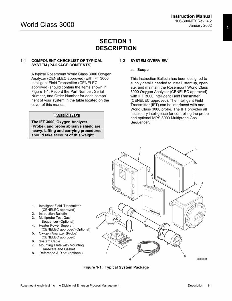
1-1 COMPONENT CHECKLIST OF TYPICALSYSTEM (PACKAGE CONTENTS)
A typical Rosemount World Class 3000 OxygenAnalyzer (CENELEC approved) with IFT 3000Intelligent Field Transmitter (CENELECapproved) should contain the items shown inFigure 1-1. Record the Part Number, SerialNumber, and Order Number for each compo-nent of your system in the table located on thecover of this manual.
The IFT 3000, Oxygen Analyzer(Probe), and probe abrasive shield areheavy. Lifting and carrying proceduresshould take account of this weight.
1-2 SYSTEM OVERVIEW
a. Scope
This Instruction Bulletin has been designed tosupply details needed to install, start up, oper-ate, and maintain the Rosemount World Class3000 Oxygen Analyzer (CENELEC approved)with IFT 3000 Intelligent FieldTransmitter(CENELEC approved). The Intelligent FieldTransmitter (IFT) can be interfaced with oneWorld Class 3000 probe. The IFT provides allnecessary intelligence for controlling the probeand optional MPS 3000 Multiprobe GasSequencer.
ROSEMOUNT
DONOTOPEN
WHILE ENERG
ISED
SEE
LABELBEFOR
EO
PENING
8
7
6
5
4
3
2
1
26030001
Figure 1-1. Typical System Package
1. Intelligent Field Transmitter(CENELEC approved)
2. Instruction Bulletin 3. Multiprobe Test Gas
Sequencer (Optional) 4. Heater Power Supply
(CENELEC approved)(Optional) 5. Oxygen Analyzer (Probe)
(CENELEC approved) 6. System Cable 7. Mounting Plate with Mounting
Hardware and Gasket 8. Reference AIR set (optional)

Instruction Manual106-300NFX Rev. 4.2January 2002
1-2 Description Rosemount Analytical Inc. A Division of Emerson Process Management
World Class 3000
The Rosemount encode sheets (Prod-uct Ordering Matrix) allow a customerto order either the hazardous area ver-sion of the IFT 3000 or the non-hazardous area version. The hazard-ous area version has the symbol"EExd" on the apparatus nameplate.The non-hazardous area version doesnot. Ensure that if you have receivedthe non-hazardous version that you donot install it in a potentially explosiveatmosphere. This also applies to thehazardous/non-hazardous versions ofthe HPS 3000.
b. System Description
The Rosemount Oxygen Analyzer (Probe) isdesigned to measure the net concentrationof oxygen in an industrial process; i.e., theoxygen remaining after all fuels have beenoxidized. The probe is permanently posi-tioned within an exhaust duct or stack andperforms its task without the use of a sam-pling system.
The equipment measures oxygen percent-age by reading the voltage developedacross a heated electrochemical cell, whichconsists of a small Yttria-stabilized, Zirconiadisc. Both sides of the disc are coated withporous metal electrodes. When operated atthe proper temperature, the millivolt outputvoltage of the cell is given by the followingNernst equation:
EMF = KT log10(P1/P2) + C
Where:
1. P2 is the partial pressure of the oxygenin the measured gas on one side of thecell,
2. P1 is the partial pressure of the oxygenin the reference gas on the other side,
3. T is the absolute temperature, 4. C is the cell constant, 5. K is an arithmetic constant.
NOTEFor best results, use clean, dry, in-strument air (20.95% oxygen) as a ref-erence gas.
When the cell is at operating temperature,and there are unequal oxygen concentra-tions across the cell, oxygen ions will travelfrom the high partial pressure of oxygenside to the low partial pressure side of thecell. The resulting logarithmic output voltageis approximately 50 mV per decade.Because the magnitude of the output isproportional to the logarithm of the inverseof the sample of the oxygen partial pres-sure, the output signal increases as theoxygen concentration of the sample gasdecreases. This characteristic enables theoxygen analyzer to provide exceptionalsensitivity at low oxygen concentrations.
Oxygen analyzer equipment measures netoxygen concentration in the presence of allthe products of combustion, including watervapor. Therefore, it may be considered ananalysis on a "wet" basis. In comparisonwith older methods, such as the Orsatapparatus, which provides an analysis on a"dry" gas basis, the "wet" analysis will, ingeneral, indicate a lower percentage ofoxygen. The difference will be proportionalto the water content of the sampled gasstream.
c. System Configuration
The equipment discussed in this manualconsists of three major components: theoxygen analyzer (CENELEC approved)(probe), the intelligent field transmitter(CENELEC approved) (IFT), and an op-tional heater power supply (CENELECapproved) (HPS). The HPS is requiredwhen the cable run between the electronicsand the probe exceeds45 m (150 ft). Thereis also an optional multiprobe test gassequencer (MPS), which can be used tofacilitate the automatic calibration of amultiple probe configuration.

Instruction Manual106-300NFX Rev. 4.2
January 2002
Rosemount Analytical Inc. A Division of Emerson Process Management Description 1-3
World Class 3000
CENELEC approved probes are available inthree length options, giving the user theflexibility to use an in situ penetration ap-propriate to the size of the stack or duct.The options on length are 457 mm (18 in.),0.91 m (3 ft), and 1.83 m (6 ft). The probe iscertified EExd IIB T1 [370°C (698°F)] toCENELEC standards EN50014 andEN50018.
The IFT contains electronics that controlprobe temperature (in conjunction with theoptional HPS) and supply power, and pro-vide isolated outputs that are proportional tothe measured oxygen concentration. Theoxygen sensing cell is maintained at a con-stant temperature by modulating the dutycycle of the probe heater. The IFT acceptsmillivolt signals generated by the sensingcell and produces outputs to be used byremotely connected devices. The IFT outputis isolated and selectable to providelinearized voltage or current.
The heater power supply CENELECapproved (HPS) can provide an interfacebetween the IFT and the probe. The HPScontains a transformer for supplying propervoltage to the probe heater. The unit iscertified EExd IIC T6 to CENELEC stan-dards EN50014 and EN50018.
Systems with multiprobe and multiple IFTapplications may employ an optional MPS3000 Multiprobe Test Gas Sequencer. TheMPS 3000 provides automatic test gassequencing for up to four probes and IFTsto accommodate automatic calibration. TheMPS 3000 must be installed in a non-hazardous, explosive-free environment.
d. System Features
1. Unique and patented electronic cellprotection action that automaticallyprotects sensor cell when the analyzerdetects reducing atmospheres.
2. Output voltage and sensitivity increaseas the oxygen concentration de-creases.
3. User friendly, menu driven operatorinterface with context-sensitive on-linehelp.
4. Field replaceable cell.
5. Analyzer constructed of rugged 316LSS for all wetted parts.
6. The intelligent field transmitter (IFT)can be located up to 45 m (150 ft) fromthe probe when used without optionalheater power supply (HPS). When thesystem includes the optional HPS, theHPS can be located up to 45 m (150 ft)from the probe and the IFT may be lo-cated up to 364 m (1200 ft) from theHPS.
7. All electronic modules are adaptable to120, 220, and 240 line voltages.
8. Five languages may be selected foruse with the IFT. These are:
EnglishFrenchGermanItalianSpanish
9. An operator can set up, calibrate, ortroubleshoot the IFT in one of twoways:
(a) Optional General User Interface(GUI). The GUI is housed withinthe IFT electronics enclosure andmakes use of an LCD display andkeypad.
(b) Optional LED Display Panel (LDP).The LED display and a limitedfunction keypad permit calibrationonly.

Instruction Manual106-300NFX Rev. 4.2January 2002
1-4 Description Rosemount Analytical Inc. A Division of Emerson Process Management
World Class 3000
e. Handling the Oxygen Analyzer
It is important that printed circuitboards and integrated circuits arehandled only when adequate antistaticprecautions have been taken to pre-vent possible equipment damage.
The oxygen analyzer is designed forindustrial application. Treat eachcomponent of the system with care toavoid physical damage. The probecontains components made from ce-ramics, which are susceptible toshock when mishandled. See SafetyData Sheets 1M03243, 1M03226, and1M03296 for safety related informa-tion.
NOTERetain packaging in which the oxygenanalyzer arrived from the factory incase any components are to beshipped to another site. This packag-ing has been designed to protect theproduct.
f. System Considerations
Prior to installation of your RosemountCENELEC approved World Class 3000Oxygen Analyzer with Intelligent FieldTransmitter make sure that you have all ofthe components necessary to make thesystem installation. Ensure that all the com-ponents are properly integrated to make thesystem functional.
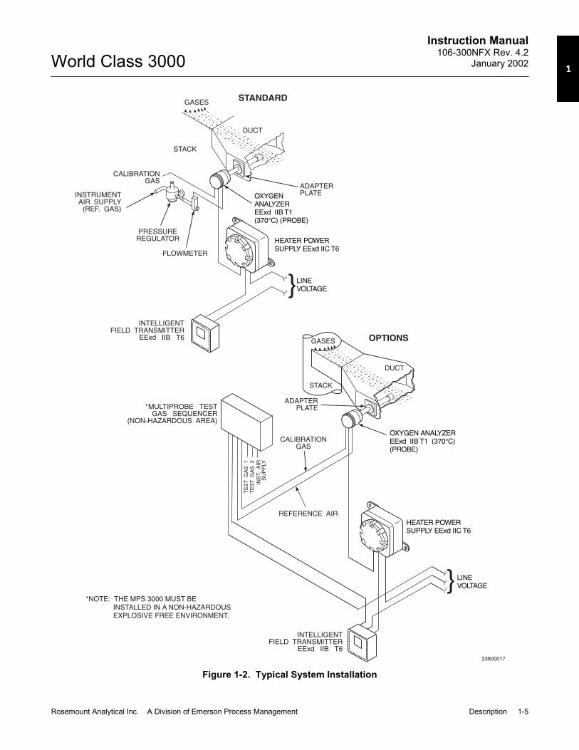
Once you have verified that you have all thecomponents, select mounting locations anddetermine how each component will beplaced in terms of available power supply,ambient temperatures, environmental con-siderations, convenience, and serviceability.A typical system installation is illustrated inFigure 1-2. Figure 1-3 shows a typicalsystem wiring. For details on installing theindividual components of the system,refer to Section 2, Installation.
After selecting the probe mounting location,provision should be made for a platformwhere the probe can be easily serviced.The intelligent field transmitter (IFT) can belocated up to 45 m (150 ft) cabling distancefrom the probe when used without optionalheater power supply (HPS). When the sys-tem includes the optional HPS, the HPS canbe located up to 45 m (150 ft) cablingdistance from the probe and the IFT may belocated up to 364 m (1200 ft) cablingdistance from the HPS.
A source of instrument air is required at theprobe for reference gas use. Since theprobe is equipped with an in-place calibra-tion feature, provision should be made forconnecting test gas tanks to the oxygenanalyzer when the probe is to be calibrated.
If the test gas bottles will be permanentlyhooked up, a check valve must be con-nected to the calibration gas fitting on theprobe junction box. This is to preventbreathing of calibration gas line and subse-quent gas condensation and corrosion. Thecheck valve is in addition to the stop valvein the test gas kit or the solenoid valve inthe multiprobe test gas sequencer units.
Instruction Manual106-300NFX Rev. 4.2
January 2002
Rosemount Analytical Inc. A Division of Emerson Process Management Description 1-5
World Class 3000
TE
ST
GA
S1
TE
ST
GA
S2
INS
T.
AIR
SU
PP
LY
OPTIONS
REFERENCE AIR
23800017
*MULTIPROBE TESTGAS SEQUENCER
(NON-HAZARDOUS AREA)
STACK
DUCT
GASES
HEATER POWERSUPPLY EExd IIC T6
HEATER POWERSUPPLY EExd IIC T6
ADAPTERPLATE
ADAPTERPLATE
LINEVOLTAGE
LINEVOLTAGE
CALIBRATIONGAS
CALIBRATIONGAS
STANDARD
DUCT
STACK
GASES
INSTRUMENTAIR SUPPLY
(REF. GAS)
PRESSUREREGULATOR
FLOWMETER
OXYGENANALYZEREExd IIB T1(370°C) (PROBE)
OXYGEN ANALYZEREExd IIB T1 (370°C)(PROBE)
INTELLIGENTFIELD TRANSMITTER
EExd IIB T6
INTELLIGENTFIELD TRANSMITTER
EExd IIB T6
*NOTE: THE MPS 3000 MUST BEINSTALLED IN A NON-HAZARDOUSEXPLOSIVE FREE ENVIRONMENT.
Figure 1-2. Typical System Installation

Instruction Manual106-300NFX Rev. 4.2January 2002
1-6 Description Rosemount Analytical Inc. A Division of Emerson Process Management
World Class 3000
*MPS 3000
TEST GASSEQUENCER
HPS 3000
HPS 3000
(OPTIONAL)
(OPTIONAL)
Explosion ProofRequired only forHazardous AreaApplications, otherwiseuse NEMA 4X.Lengths Exceeding150 feet.
2-Conductor T/CWire [46 (150) max]
(optional)Line Voltage
Line Voltage
Line Voltage
Line Voltage
2-Conductor T/CWire [46 (150) max]
(optional)
4 Twisted Pair Plus 2 Twisted Pairfor Options [366 (1200) max]
5 Conductor[305 (1000) max]
Modular DesignUp to 4 Probes
IFT 3000
IFT 3000
Intelligent Field Transmitter
Line Voltage100 to 120 Volt220 to 240 Volt
Intelligent Field Transmitter
Line Voltage100 to 120 Volt220 to 240 Volt
Stack Thermocouple(optional)
Stack Thermocouple(optional)
World Class 3000Probe
World Class 3000Probe
7-Conductor Cable[46 (150) max]
7-Conductor Cable[46 (150) max]
2-Pneumatic Linesby Customer
[91 (300) max]
Test Gasby
Customer
[HPS not required for lengths of less than 46 (150) max]
P00003
*NOTE 1:
NOTE 2:
THE MPS 3000 MUST BE INSTALLEDIN A NON-HAZARDOUS EXPLOSIVE FREEENVIRONMENT.
ALL DIMENSIONS APPEAR IN METERSWITH FEET IN PARENTHESES.
Figure 1-3. World Class 3000 Typical Applicationwith Intelligent Field Transmitters - CENELEC Approved

Instruction Manual106-300NFX Rev. 4.2
January 2002
Rosemount Analytical Inc. A Division of Emerson Process Management Installation 2-1
World Class 3000
SECTION 2INSTALLATION
2-1 OXYGEN ANALYZER (PROBE)INSTALLATION
Before probe installations, consultprobe Safety Data Sheet 1M03226.
The probe and probe abrasive shieldare heavy. Use proper lifting andcarrying procedures to avoidpersonnel injury.
Install all protective equipment coversand safety ground leads after installa-tion. Failure to install covers andground leads could result in seriousinjury or death.
a. Selecting Location
1. The location of the probe in the stackor flue is most important for maximumaccuracy in the oxygen analyzing pro-cess. The probe must be positioned sothat the gas it measures is representa-tive of the process. Best results arenormally obtained if the probe is posi-tioned near the center of the duct (40to 60% insertion). A point too near theedge or wall of the duct may not pro-vide a representative sample becauseof the possibility of gas stratification. Inaddition, the sensing point should beselected so that the process gas tem-perature falls within a range of 10° to704°C (50° to 1300°F). Figure 2-1
provides you with mechanical installa-tion references.
2. Check the flue or stack for holes andair leakage. The presence of thiscondition will substantially affect theaccuracy of the oxygen reading.Therefore, either make necessaryrepairs or install the probe upstreamof any leakage.
3. Ensure that the area is clear ofobstructions internal and external thatwill interfere with installation. Allowadequate clearance for removal ofprobe (Figure 2-1).
Do not allow the temperature of theprobe junction box to exceed 150°C(302°F) or damage to the unit mayresult. If the probe junction box tem-perature exceeds 150°C (302°F), theuser must fabricate a heat shield orprovide adequate cooling air to theprobe junction box.
b. Mechanical Installation
1. Ensure that all components are avail-able for installation of the probe. Checkthe ceramic filter to ensure that it is notdamaged and that the system cable isthe required length.
2. The probe may be installed intact as itis received. It is recommended that youdisassemble the adapter plate for eachinstallation.
3. Weld or bolt adapter plate (Figure 2-1)onto the duct.

Instruction Manual106-300NFX Rev. 4.2January 2002
2-2 Installation Rosemount Analytical Inc. A Division of Emerson Process Management
World Class 3000
BO
TT
TO
MV
IEW
CE
NE
LE
CA
PP
RO
VE
DW
OR
LD
CL
AS
SP
RO
BE
WIT
HS
NU
BB
ER
DIF
FU
SO
R
AB
AB
VIE
WA
-AV
IEW
B-B
DIM
"A"
23800006
76
(3.0
)D
IAM
AX
DIM
"B"
RE
MO
VA
LE
NV
EL
OP
E
20
0(7
.87
)
11
0(4
.33
)
EL
EC
TR
ICA
LC
ON
NE
CT
ION
NO
TE
:D
IME
NS
ION
SA
RE
INM
ILL
IME
TE
RS
WIT
HIN
CH
ES
INP
AR
EN
TH
ES
ES
UN
LE
SS
OT
HE
RW
ISE
IND
ICA
TE
D.P
RO
CE
SS
FL
OW
MU
ST
BE
INT
HIS
DIR
EC
TIO
NW
ITH
RE
SP
EC
TT
OV
EE
SH
IEL
DW
HE
NU
SIN
GO
PT
ION
AL
CE
RA
MIC
DIF
FU
SO
R.
EX
TE
RN
AL
EA
RT
H(H
AR
DW
AR
E)
INT
ER
NA
LE
AR
TH
(TE
RM
INA
L6
) (RO
TA
TE
D9
0C
CW
)IN
STA
LL
WIT
HC
ON
NE
CT
ION
SA
TB
OT
TO
M
o
1.5
7(0
.06
2)
TH
KG
AS
KE
T(P
/N1
M0
32
37
H0
1)
TA
BL
EI.
MO
UN
TIN
GF
LA
NG
ETA
BL
EII.
RE
MO
VA
L/IN
STA
LL
AT
ION
DIM
EN
SIO
NS
MM
(IN
.)
DIM
EN
SIO
NS
MM
(IN
.)D
IND
IM"A
"D
IM"B
"
FL
AN
GE
DIA
HO
LE
SIZ
ED
IA
4H
OL
ES
EQ
SP
ON
B.C
.D
IA
1U
05
68
0G
01
18
IN.P
RO
BE
S
1U
05
68
0G
02
3F
TP
RO
BE
S
1U
05
68
0G
03
6F
TP
RO
BE
S
21
0(8
.25
)
18
(0.7
08
)
17
0(6
.69
3)
45
9(1
8.0
7)
91
3(3
5.9
5)
18
31
(72
.09
)
75
5(2
9.7
)
12
09
(47
.6)
21
26
(83
.7)
Figure 2-1. Probe Installation (Sheet 1 of 5)

Instruction Manual106-300NFX Rev. 4.2
January 2002
Rosemount Analytical Inc. A Division of Emerson Process Management Installation 2-3
World Class 3000
1.5
2(0
.06
)T
HK
GA
SK
ET
(P/N
45
07
C5
2H
03
)F
UR
NIS
HE
DIN
HA
RD
WA
RE
PA
CK
AG
E
DIF
FU
SO
R/D
US
TS
EA
LH
UB
(P/N
1U
05
67
7G
03
)
NO
TE
:D
IME
NS
ION
SA
RE
INM
ILL
IME
TE
RS
WIT
HIN
CH
ES
INP
AR
EN
TH
ES
ES
UN
LE
SS
OT
HE
RW
ISE
IND
ICA
TE
D.
EL
EC
TR
ICA
LC
ON
NE
CT
IONSE
ES
HE
ET
1F
OR
CO
NN
EC
TIO
ND
ETA
ILS
RE
F,V
EN
T,
AN
DC
AL
GA
SC
ON
NE
CT
ION
S
DIM
EN
SIO
NS
MM
(IN
.)
RE
MO
VA
L/IN
STA
LL
AT
ION
DIM
"D"
(RE
MO
VA
LE
NV
EL
OP
E)
DIM
"C"
18
IN.P
RO
BE
1U
05
68
0G
04
SH
IEL
D1
N0
49
66
H0
1
3F
TP
RO
BE
1U
05
68
0G
05
SH
IEL
D1
N0
49
66
H0
2
6F
TP
RO
BE
1U
05
68
0G
06
SH
IEL
D1
N0
49
66
H0
3
76
9(3
0.3
)
12
24
(48
.2)
21
44
(84
.4)
38
7(1
5.3
)
84
3(3
3.2
)
17
62
(69
.4)
DIM
"C"
17
8(7
.00
)
37
8(1
4.9
)
DIM
"D"
(RE
MO
VA
LE
NV
EL
OP
E)
AB
RA
SIV
ES
HIE
LD
INS
TA
LL
AT
ION
WIT
HC
EN
EL
EC
AP
PR
OV
ED
WO
RL
DC
LA
SS
30
00
CH
EC
KV
ALV
E
23800007
Figure 2-1. Probe Installation (Sheet 2 of 5)

Instruction Manual106-300NFX Rev. 4.2January 2002
2-4 Installation Rosemount Analytical Inc. A Division of Emerson Process Management
World Class 3000
BO
TT
TO
MV
IEW
OP
TIO
NA
LC
ER
AM
ICD
IFF
US
OR
WIT
HV
EE
DE
FL
EC
TO
R
AB
AB
VIE
WA
-AV
IEW
B-B
DIM
"A"
23800011
76
(3.0
)D
IAM
AX
DIM
"B"
RE
MO
VA
LE
NV
EL
OP
E
20
0(7
.87
)
11
0(4
.33
)
EL
EC
TR
ICA
LC
ON
NE
CT
ION
NO
TE
:D
IME
NS
ION
SA
RE
INM
ILL
IME
TE
RS
WIT
HIN
CH
ES
INP
AR
EN
TH
ES
ES
UN
LE
SS
OT
HE
RW
ISE
IND
ICA
TE
D.P
RO
CE
SS
FL
OW
MU
ST
BE
INT
HIS
DIR
EC
TIO
NW
ITH
RE
SP
EC
TT
OV
EE
SH
IEL
D.
EX
TE
RN
AL
EA
RT
H(H
AR
DW
AR
E)
INT
ER
NA
LE
AR
TH
(TE
RM
INA
L6
) (RO
TA
TE
D9
0C
CW
)IN
STA
LL
WIT
HC
ON
NE
CT
ION
SA
TB
OT
TO
M
o
1.5
7(0
.06
2)
TH
KG
AS
KE
T(P
/N1
M0
32
37
H0
1)
TA
BL
EI.
MO
UN
TIN
GF
LA
NG
ETA
BL
EII
.R
EM
OV
AL
/IN
STA
LL
AT
ION
DIM
EN
SIO
NS
MM
(IN
.)
DIM
EN
SIO
NS
MM
(IN
.)D
IND
IM"A
"D
IM"B
"
FL
AN
GE
DIA
HO
LE
SIZ
ED
IA
4H
OL
ES
EQ
SP
ON
B.C
.D
IA
1U
05
68
0G
01
18
IN.
PR
OB
ES
1U
05
68
0G
02
3F
TP
RO
BE
S
1U
05
68
0G
03
6F
TP
RO
BE
S
21
0(8
.25
)
18
(0.7
08
)
17
0(6
.69
3)
55
4(2
1.8
1)
10
08
(39
.68
)
19
26
(75
.83
)
75
5(2
9.7
)
12
09
(47
.6)
21
26
(83
.7)
Figure 2-1. Probe Installation (Sheet 3 of 5)

Instruction Manual106-300NFX Rev. 4.2
January 2002
Rosemount Analytical Inc. A Division of Emerson Process Management Installation 2-5
World Class 3000
NO
TE
:D
IME
NS
ION
SA
RE
INM
ILL
IME
TE
RS
WIT
HIN
CH
ES
INP
AR
EN
TH
ES
ES
UN
LE
SS
OT
HE
RW
ISE
IND
ICA
TE
D.
P00006
DIM
EN
SIO
NS
MM
(IN
.)
TA
BL
EIV
.M
OU
NT
ING
PL
AT
E:
PR
OB
ET
OS
TA
CK
(NE
WIN
STA
LL
AT
ION
S)
DIN
"A"
"B"
TH
RE
AD
"C"
DIA
21
5(8
.5)
M-1
6x
2
17
0(6
.7)
DIM
EN
SIO
NS
MM
(IN
.)
TA
BL
EIII.
MO
UN
TIN
GP
LA
TE
:A
BR
AS
IVE
SH
IEL
DT
OS
TA
CK
(NE
WIN
STA
LL
AT
ION
S)
DIN
"A"
"B"
DIA
"C"
TH
RE
AD
23
5(9
.25
)
10
0(3
.94
)
M-2
0x
2.5
MO
UN
TIN
GP
LA
TE
OU
TL
INE
MO
UN
TIN
GP
LA
TE
FO
R1
8IN
.,3
FT
AN
D6
FT
AB
RA
SIV
ES
HIE
LD
INS
TA
LL
AT
ION
SS
EE
SH
EE
T2
.
"A"
"B"
"C"
8T
HR
EA
DE
DH
OL
ES
EQ
UA
LLY
SP
AC
ED
ON
18
9.9
92
(7.4
8)
DIA
B.C
.
"A"
22
.5o
MO
UN
TIN
GP
LA
TE
FO
RC
EN
EL
EC
WO
RL
DC
LA
SS
30
00
PR
OB
EIN
STA
LL
AT
ION
SS
EE
SH
EE
T1
.
"A"
"A"
"C"
DIA
82
.5(3
.25
)D
IA
4S
TU
DS
,L
OC
KW
AS
HE
RS
,A
ND
NU
TS
,E
QU
AL
LY
SP
AC
ED
ON
"C"
DIA
B.C
.
Figure 2-1. Probe Installation (Sheet 4 of 5)

Instruction Manual106-300NFX Rev. 4.2January 2002
2-6 Installation Rosemount Analytical Inc. A Division of Emerson Process Management
World Class 3000
PROBE MOUNTING
ABRASIVE SHIELD MOUNTING
INSTALLATION FOR MASONRYWALL STACK CONSTRUCTION
INSTALLATION FOR METALWALL STACK OR DUCT
CONSTRUCTION
13 (0.50)
95 (3.75)
MIN DIA HOLEIN WALL
STACK OR DUCTMETAL WALL
MTG HOLESSHOWN ROTATED
22.5 OUT OFTRUE POSITION
o
WELD OR BOLTMOUNTING PLATE TO
METAL WALL OF STACKOR DUCT. JOINT MUST
BE AIR TIGHT.
13 (0.50)
114 (4.50)O.D. REF
PIPE 4.00 SCHED 40PIPE SLEEVE (NOTBY ROSEMOUNT)LENGTH BY CUSTOMER
MASONRYSTACK WALL
OUTSIDE WALLSURFACE
JOINT MUSTBE AIRTIGHT
MTG HOLESSHOWN ROTATED
22.5 OUT OFTRUE POSITION
o
FIELD WELDPIPE TO
ADAPTOR PLATE
BOLT ADAPTORPLATE TO OUTSIDE
WALL SURFACE
NOTE: ALL MASONRY STACK WORK AND JOINTS EXCEPTMOUNTING PLATE NOT FURNISHED BY ROSEMOUNT.
82.5 (3.25)
MIN DIA HOLEIN WALL
STACK OR DUCTMETAL WALL
WELD OR BOLT MOUNTINGPLATE TO METAL WALL
OF STACK OR DUCT.JOINT MUST BE AIR TIGHT.
FIELD WELDPIPE TOADAPTOR PLATE
102 (4.0)O.D. REF
PIPE 3.5 SCHED 40PIPE SLEEVE (NOTBY ROSEMOUNT)LENGTH BY CUSTOMER
MASONRYSTACK WALLOUTSIDE WALL
SURFACE
JOINT MUSTBE AIRTIGHT
BOLT MOUNTINGPLATE TO OUTSIDE
WALL SURFACE
P00007
Figure 2-1. Probe Installation (Sheet 5 of 5)

Instruction Manual106-300NFX Rev. 4.2
January 2002
Rosemount Analytical Inc. A Division of Emerson Process Management Installation 2-7
World Class 3000
4. If using the optional ceramic diffuserelement, the vee deflector must be cor-rectly oriented. Before inserting theprobe, check the direction of flow of thegas in the duct. Orient the vee deflectoron the probe so that the apex pointsupstream toward the flow (Figure 2-2).This may be done by loosening thesetscrews, and rotating the vee de-flector to the desired position.Retighten the setscrews.
5. In horizontal installations, the probecover should be oriented so that thesystem cable drops vertically from theprobe cover. In a vertical installation,the system cable can be oriented inany direction.
6. If the system has an abrasive shield,check the diffusion element dust sealpackings. The joints in the two pack-ings must be staggered 180°. Also,make sure that the packings are in thehub grooves as the probe slides intothe 15° forcing cone in the abrasiveshield.
NOTEIf process temperatures will exceed1000°F (538°C), use anti-seize com-pound on stud threads to ease futureremoval of probe.
APEX
FILTER
GAS FLOWDIRECTION
VEEDEFLECTOR
CERAMICDIFFUSIONELEMENT
VEEDEFLECTOR
SETSCREW
23800008
Figure 2-2. Orienting the Optional Vee Deflector
7. Insert the probe through the opening inthe mounting flange and bolt the unit tothe flange.
8. Ensure that probe is properly earthedby way of both the internal and externalpoints.
9. Ensure that the installation does notobscure the messages on either theprobe nameplate or the junction boxlid.

Instruction Manual106-300NFX Rev. 4.2January 2002
2-8 Installation Rosemount Analytical Inc. A Division of Emerson Process Management
World Class 3000
c. Reference Air Package
After the oxygen analyzing (probe) unit isinstalled, connect the reference gas air setto the probe cover. The reference gas airset should be installed in accordance withFigure 2-3.
d. Service Required.
1. Power input: 44 VAC from HPS 3000or IFT 3000.
2. Compressed air: 68.95 kPa (10 psig)minimum, 1551.38 kPa (225 psig)
maximum at 56.6 L/hr (2 scfh) maxi-mum; supplied by one of the following(less than 40 parts-per-million total hy-drocarbons).
(a) Instrument air - clean, dry.
(b) Bottled standard air with step-downregulator.
(c) Bottled compressed gas mixture(20.95% oxygen in nitrogen).
(d) Other equivalent clean, dry, oil-freeair supply.
17300016
TO PROBEJUNCTION BOX
REF GAS SET263C152G01
1 FLOWMETER 0.2-2.0 SCFH 771B635H02
2 2" PRESSURE GAGE 0-15 PSIG 275431-006
3 COMBINATION FILTER-REG. 0-30 PSIG 4505C21G01
NOTE: DIMENSIONS ARE IN MILLIMETERSWITH INCHES IN PARENTHESES.
12
3
122.17 (4.81)
FLOW SETPOINT KNOB
0.125-27 NPT FEMALEOUTLET CONNECTION
30.22(1.19)
254 REF(10.0)
DRAIN VALVE
79.25 (3.12) MAX
215.90 MAX(8.50)
50.80(2.0) 2 MOUNTING HOLES
81.03 (3.19) LGTHROUGH BODY FOR7.92 (0.312) DIA BOLTS
38.10(1.50)
57.15 (2.250)
SCHEMATIC HOOKUP FOR REFERENCE AIR SUPPLY ON OXYGEN ANALYZER PROBE HEAD.
OUTLET
0.25-18 NPT FEMALEINLET CONNECTION
COMPRESSED AIR SUPPLY10-225 PSIG MAX PRESSURE
6 (0.250) OD TUBING(SUPPLIED BY CUSTOMER)
6 (0.250) ODTUBE COMPRESSION
FITTING (SUPPLIED BY WECO)
NOTE: DIMENSIONS ARE IN MILLIMETERSWITH INCHES IN PARENTHESES.
Figure 2-3. Air set, Plant Air Connection
Instruction Manual106-300NFX Rev. 4.2
January 2002
Rosemount Analytical Inc. A Division of Emerson Process Management Installation 2-9
World Class 3000
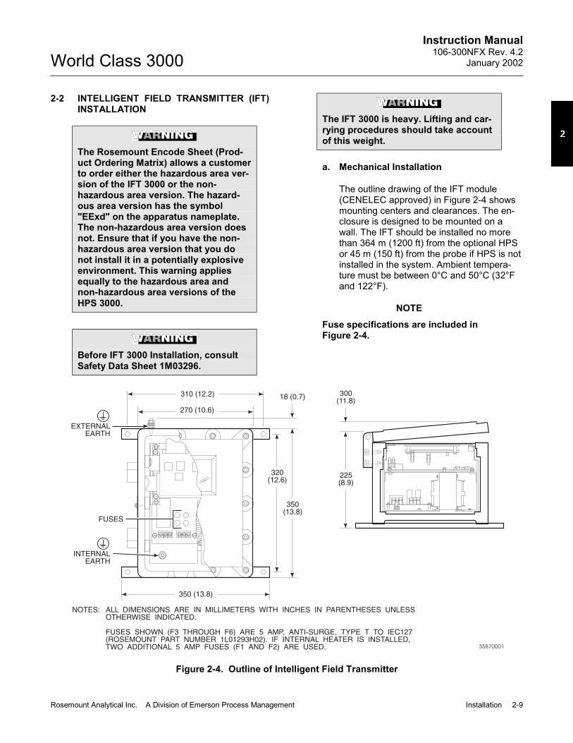
2-2 INTELLIGENT FIELD TRANSMITTER (IFT)INSTALLATION
The Rosemount Encode Sheet (Prod-uct Ordering Matrix) allows a customerto order either the hazardous area ver-sion of the IFT 3000 or the non-hazardous area version. The hazard-ous area version has the symbol"EExd" on the apparatus nameplate.The non-hazardous area version doesnot. Ensure that if you have the non-hazardous area version that you donot install it in a potentially explosiveenvironment. This warning appliesequally to the hazardous area andnon-hazardous area versions of theHPS 3000.
Before IFT 3000 Installation, consultSafety Data Sheet 1M03296.
The IFT 3000 is heavy. Lifting and car-rying procedures should take accountof this weight.
a. Mechanical Installation
The outline drawing of the IFT module(CENELEC approved) in Figure 2-4 showsmounting centers and clearances. The en-closure is designed to be mounted on awall. The IFT should be installed no morethan 364 m (1200 ft) from the optional HPSor 45 m (150 ft) from the probe if HPS is notinstalled in the system. Ambient tempera-ture must be between 0°C and 50°C (32°Fand 122°F).
NOTEFuse specifications are included inFigure 2-4.
310 (12.2)
EXTERNALEARTH
INTERNALEARTH
FUSES
NOTES: ALL DIMENSIONS ARE IN MILLIMETERS WITH INCHES IN PARENTHESES UNLESSOTHERWISE INDICATED.
FUSES SHOWN (F3 THROUGH F6) ARE 5 AMP, ANTI-SURGE, TYPE T TO IEC127(ROSEMOUNT PART NUMBER 1L01293H02). IF INTERNAL HEATER IS INSTALLED,TWO ADDITIONAL 5 AMP FUSES (F1 AND F2) ARE USED.
18 (0.7) 300(11.8)
350 (13.8)
270 (10.6)
350(13.8)
225(8.9)
320(12.6)
35870001
Figure 2-4. Outline of Intelligent Field Transmitter

Instruction Manual106-300NFX Rev. 4.2January 2002
2-10 Installation Rosemount Analytical Inc. A Division of Emerson Process Management
World Class 3000
ALWAYS DISCONNECT LINE VOLTAGEFROM INTELLIGENT FIELD TRANSMITTERBEFORE CHANGING JUMPERS.
JUMPERCONFIGURATION
LINE VOLTAGESELECTION
JUMPER(INSTALL)
PROBE HEATERVOLTAGE SELECTION
JUMPER(INSTALL)
120 V.A.C.
220 V.A.C.
240 V.A.C.
JM8, JM7, JM1
JM6, JM5, JM2
JM6, JM5, JM1
WORLD CLASS PROBE (44V) JM10
P00010
If you reconfigure the equipment for a line voltage other than the one marked on the seriallabel and the mains filter of the power supply then you should change the marking on theserial label and the mains filter to state the new line voltage.
If incorrect heater voltage is selected, damage to the probe may occur. For HPS voltageselection jumper, refer to Figure 2-15.
Figure 2-5. Power Supply Board Jumper Configuration
b. Electrical Connections
1. The IFT can be configured for 100,120, 220, or 240 line voltages. For 120Vac usage, install JM8, JM7, and JM1.For 220 Vac usage, install jumpersJM6, JM5, JM2 (refer to Figure 2-5 andFigure 2-6).
If you reconfigure the equipment for aline voltage other than the one markedon the serial label and the mains filterof the power supply you shouldchange the marking on the serial labeland the mains filter to state the newline voltage.
2. The IFT can be configured to connectdirectly to a probe or to an optionalHPS. The electrical connections for anon-HPS equipped system should bemade as described in the electrical in-stallation diagram, Figure 2-7.
Do not install jumper JM6 on the mi-croprocessor board, or JM1 on the in-terconnect board, if an HPS isinstalled in the system. This will resultin system failure.
3. The IFT must have JM6 on the micro-processor board (Figure 2-8 and Figure2-9) and JM1 on the interconnectboard (Figure 2-10 and Figure 2-11)installed if an HPS is not installed inthe system.
4. If an MPS is not used in the system,wire jumper between CAL RET and NOGAS must be installed on the intercon-nect board. Remove wire jumper ifMPS is installed in the system. Refer toFigure 2-7, note 6.
5. The power cable should comply withthe safety regulations in the user'scountry and should not be smaller than16 gauge, 3 amp.

Instruction Manual106-300NFX Rev. 4.2
January 2002
Rosemount Analytical Inc. A Division of Emerson Process Management Installation 2-11
World Class 3000
P00011
THIS TERMINAL BLOCKIS A 44VAC OUTPUTSPECIFICALLY FORPOWERING THEWC 3000 PROBE.!
Figure 2-6. IFT Power Supply Board Jumpers

Instruction Manual106-300NFX Rev. 4.2January 2002
2-12 Installation Rosemount Analytical Inc. A Division of Emerson Process Management
World Class 3000
LG. BR
GN/YE
BL
SHIELD
SHIELD
SHIELD
CAL RET
NO GAS
LO GAS
HI GAS
IN GAS
SHIELD
SHIELD
STACK TC -
STACK TC +
PROBEMV+
PROBE MV -
PROBE TC +
PROBE TC -GN
RD
WH
SM.BR
WH
SM. BR
GN
RD
INTELLIGENT FIELDTRANSMITTER IFT3000
WC 3000 PROBE(CENELEC APPROVED)
1 2 3 4 5 6 7 8
WH
SM
.B
R
RD
GN
PROBE INTERIOR
GN
/YE
BL
LG
.B
R
GN
CE
LL
-VE
OR
CE
LL
+V
E
YE
CH
RO
ME
L
RD
AL
UM
EL
GN
BK
BKH
EA
TE
R
PROBE JUNCTIONBOX WIRING
STACK TC WIRING AS REQUIRED
SPECIAL PROBE CABLE BETWEEN PROBE ANDIFT BY ROSEMOUNT (FITTED WITH EExdGLANDS)
INSTALL JM1 ON INTERCONNECT BOARD
INSTALL JM6 ON MICROPROCESSOR BOARD
IF STACK TEMPERATURE NOT USED
IF MPS 3000 NOT USED
1 RELAY PER PROBE AVAILABLE FORCALIBRATION STATUS INDICATION(48 V max, 100 mA max)
CABLE COLORS SHOWN HERE APPLY TOROSEMOUNT SUPPLIED SPECIAL CABLE FITTEDWITH EExd GLANDS(P/N 1U03066)
NOTES
ALWAYS DISCONNECT LINE VOLTAGEFROM INTELLIGENT FIELD TRANSMITTERBEFORE CHANGING JUMPERS.
LINEVOLTAGESECTION
JUMPER(INSTALL)
PROBE HEATERVOLTAGE SECTION
JUMPER(INSTALL)
120 V.A.C.
220 V.A.C.
240 V.A.C.
J1
J5 J6
J1
JM1
JM5JM6
J2J3
J4J5
J6J7
J8J9
3D39122G REV
POWER SUPPLY BOARD
3D3911BG REV
MICROPROCESSOR BOARD
3D39120G REV
INTERCONNECT BOARD
JM8, JM7, JM1
JM6, JM5, JM2
JM6, JM5, JM1
WORLD CLASS PROBE
218 PROBE
JM10
JM9
JUMPER CONFIGURATION
CA
LR
ET
CA
LR
ET
CA
LR
ET
CA
LR
ET
HI
GA
S
HI
GA
S
HI
GA
S
HI
GA
S
INC
AL
INC
AL
INC
AL
INC
AL
NO
GA
S
NO
GA
S
NO
GA
S
NO
GA
S
LO
GA
S
LO
GA
S
LO
GA
S
LO
GA
S
NC NC NCNC C C CC NO NO NONO
J13 J14 J15 J16 J17 J18 J12
J9LINE INLL
NN
J8J7J6J5J4J3J2J1LINE OUT
J10
J11
PROBE 1
PROBE 1
PROBE 2
PROBE 2
PROBE 3
PROBE 3
PROBE 4
PROBE 4
J19 J20 J21 J22
3D39064G REV
5 CONDUCTOR SHIELDED CABLEPER PROBE #16 AWG BY CUSTOMER
L
E
E
N
N
L
LINEVOLTAGE
LINEVOLTAGE
MPS TERMINATION BOARDMPS3000 MULTI GAS SEQUENCER (OPTIONAL)
ERH
35870007
Figure 2-7. Wiring Layout for IFT 3000 (CENELEC approved) System without HPS

Instruction Manual106-300NFX Rev. 4.2
January 2002
Rosemount Analytical Inc. A Division of Emerson Process Management Installation 2-13
World Class 3000
JM7
JM6
J4
SW
1
TOI/
OB
OA
RD
3D39513GREV TO LDP CARD
TOP
OW
ERS
UP
PLY
CA
RD
TP4
+30V
ISO
-CG
ND
C+5
VIS
O-C
TP5
TP6
TO GUI CARD
J3
J2J1
TP1
-5V
TP2
+15V
TP8
+5V
TP3
-15V
TP7
JM7CURRENT/VOLTAGESELECTOR SWITCH
JM6
29850004
Figure 2-8. IFT Microprocessor Board Jumper Configuration

Instruction Manual106-300NFX Rev. 4.2January 2002
2-14 Installation Rosemount Analytical Inc. A Division of Emerson Process Management
World Class 3000
OUTPUT JUMPER
HPSProbe (No HPS)
Remove JM6Install JM6
(See Figure 2-8 for jumper locations.)
Figure 2-9. IFT Microprocessor Board Jumpers
OUTPUT JUMPER
HPSProbe (No HPS)
Remove JM1Install JM1
Figure 2-10. Interconnect Board JumperConfiguration
6. Before supplying power to the IFT, ver-ify that the jumpers have been properlyset in the IFT, Figure 2-5, Figure 2-8,and Figure 2-10.
7. Terminal strip J5 on the power supplyboard is used for supplying the IFT withpower. Terminal strip J6 on the powersupply board is used to supply theprobe heater with power if an HPS isnot used (Figure 2-6).
8. Ensure that the IFT 3000 is properlyearthed by way of both the internal andexternal earthing hardware.
9. Ensure that the installation does notobscure the message on either the IFTnameplate or the IFT lid.
c. Analog Output and Relay OutputConnections
1. The microprocessor board has aswitch to select voltage or current op-erations. Figure 2-8 shows the switchlocation. In voltage mode, output is 0-10 V. In the current mode, the outputcan be configured from the setup menuto be 0-20 mA or 4-20 mA.
2. The analog output and relay outputsare programmed by the user asneeded. The analog output is typicallysent to recording equipment such aschart recorders. Relay outputs are typi-cally sent to annunciators.
3. Relays K1 and K2 are user configur-able from the PROBE SETUP sub-menu (Table 3-5). Typically these areused to indicate O2 values above orbelow specified tolerances. OK relay isenergized when unit is functioningproperly.
4. All wiring must conform to local andnational codes.
5. Connect the analog output and relayoutputs as shown in Figure 2-11.

Instruction Manual106-300NFX Rev. 4.2
January 2002
Rosemount Analytical Inc. A Division of Emerson Process Management Installation 2-15
World Class 3000
22
11
33
44
55
66
77
88
99
1010
1111
1212
1313
1414
1515
1616
1717
1818
1919
2020
2121
2222
2323
2424 OK-COM
OK-NO
K1-COM
K1-NO
K2-COM
K2-NO
ANOUT-ANOUT+
STACK T/C
STACK T/C
PROBE T/C
PROBE T/C
PROBE MV-
PROBE MV+
OK-NC
K1-NC
K2-NC
CAL INIT-2
CAL INIT-1
CALRET
NOGAS
LOGAS
HIGAS
INCAL
RELAY-RELAY+
AD590-AD590+
TRIAC-
TRIAC+ JM1(UNDERSHIELD)
NOTES:
DENOTES SHIELD CONNECTION.
OK RELAY IS ENERGIZED WHENUNIT IS FUNCTIONING PROPERLY.
730002
Figure 2-11. IFT Interconnect Board Output Connections

Instruction Manual106-300NFX Rev. 4.2January 2002
2-16 Installation Rosemount Analytical Inc. A Division of Emerson Process Management
World Class 3000
2-3 HEATER POWER SUPPLY INSTALLATION
The Rosemount encode sheets (Prod-uct Ordering Matrix) allow a customerto order either the hazardous area ver-sion of the HPS 3000 or the non-hazardous area version. The hazard-ous area version has the symbol"EExd" on the apparatus nameplate.The non-hazardous area version doesnot. Ensure that if you have receivedthe non-hazardous version that you donot install it in a potentially explosiveatmosphere. This also applies to thehazardous/non-hazardous version ofthe IFT 3000.
Before HPS installation, consult SafetyData Sheet 1M03243.
a. Mechanical Installation
The outline drawing of the CENELEC ap-proved heater power supply enclosure inFigure 2-12, shows mounting centers andclearances. The CENELEC approved en-closure is designed to be mounted on a wallor bulkhead. The heater power supplyshould be installed no further than 45 m(150 ft) from the probe. The heater powersupply must be located in a location freefrom significant ambient temperaturechanges and electrical noise. Ambient tem-perature must be between 0° to 60°C (32°to 140°F).
b. Electrical Connections
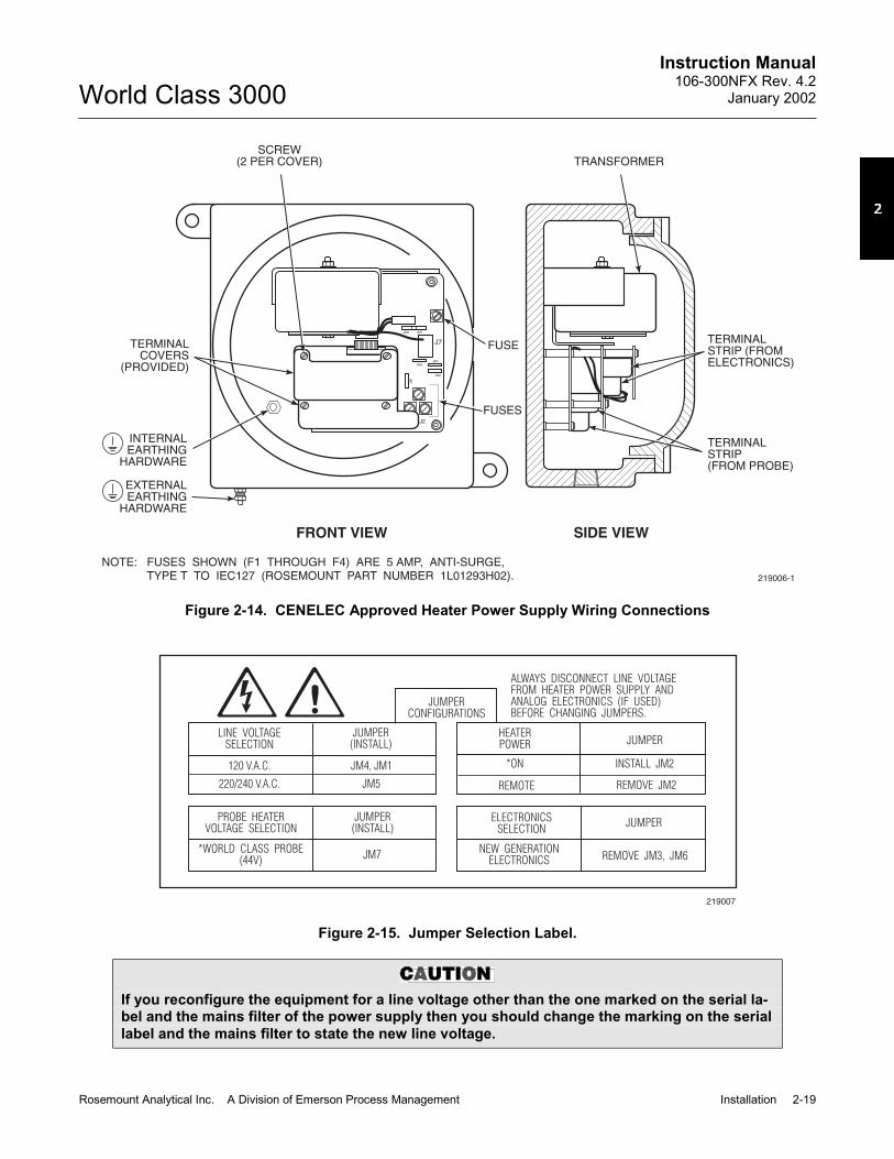
1. Electrical connections should be madeas described in the electrical installa-tion diagram, Figure 2-13. The wiringterminals are divided into two layers:the bottom (FROM PROBE) terminalsshould be connected first, the top(FROM ELECTRONICS) terminalsshould be connected last (Figure 2-14).Each terminal strip has a protectivecover which must be removed whenmaking connections. To remove the
253(9.96)
233(9.17)
120(4.72)
157(6.18)
216.0(8.50)
264.0(10.39)
EExd IIC T6ENCLOSURE
14.22 (0.56) DIAMTG HOLE (2 PLS)
NOTE: DIMENSIONS ARE IN MILLIMETERSWITH INCHES IN PARENTHESESUNLESS OTHERWISE INDICATED. 219005
Figure 2-12. Outline of CENELEC Approved HeaterPower Supply
terminal covers, remove two slottedscrews holding cover in place. Alwaysreinstall terminal covers after makingconnections.
2. Power Input: 120, 220 or 240 Vac. For120 Vac usage, install jumpers JM4and JM1 and remove JM5 if installed.For 220 or 240 Vac usage, installjumper JM5 and remove JM1 and JM4if installed (see label, Figure 2-15).
If you reconfigure the equipment for aline voltage other than the one markedon the serial label and the mains filterof the power supply then you shouldchange the marking on the serial labeland the mains filter to state the newline voltage.
NOTEFuse specifications are shown inFigure 2-14.

Instruction Manual106-300NFX Rev. 4.2
January 2002
Rosemount Analytical Inc. A Division of Emerson Process Management Installation 2-17
World Class 3000
+
+
+
+
+
+
+
+
+
-
-
-
-
-
-
-
-
-
BK WHJ9
J8
J3
J2 J1
TRIAC RELAYSTACK
TCANALOGHEATER
PROBEMV
PROBEMV
PROBETC
PROBETC
AD590
SM. BR CELL+
RD HTR TC +
WH CELL -
GN HTR TC -
LG. BR
BL
GN/YE
STACKTC
PROBEHEATER
R H N L
LINEVOLTAGESHIELD
TOP
BOTTOM
4 TWISTED PAIR SHIELDED#22 AWG BY CUSTOMER
2 TWISTED PAIR SHIELDED#22 AWG BY CUSTOMER(OPTIONAL)
HPS 3000 INTERFACE MODULE
LINE
WC PROBE 3000 CENELEC APPROVED
1 2 3 4 5 6 7 8
WH
SM
.B
R
RD
GN
PROBE INTERIOR
GN
/YE
BL
LG
.B
R
GN
CE
LL
-VE
OR
CE
LL
+V
E
YE
CH
RO
ME
L
RD
AL
UM
EL
GN
BK
BKH
EA
TE
R
PROBE JUNCTIONBOX WIRING
ALWAYS DISCONNECT LINE VOLTAGEFROM HEATER POWER SUPPLY ANDANALOG ELECTRONICS (IF USED)BEFORE CHANGING JUMPERS.
JUMPERCONFIGURATIONS
LINE VOLTAGESELECTION
JUMPER(INSTALL)
JUMPER(INSTALL)
HEATERPOWER JUMPER
120 V.A.C.
220/240 V.A.C.
JM4, JM1
JM5
REMOTE
ON
REMOVE JM2
INSTALL JM2
ELECTRONICSSELECTION
JUMPERPROBE HEATER
VOLTAGE SECTION
REMOVE JM3, JM6NEW GENERATIONELECTRONICS
WORLD CLASS PROBE JM7
RELAY WIRE IS OPTIONAL; RELAY CAN BE PERMANENTLYENABLED WITH JUMPER IF NOT USED
STACK TC WIRING AS REQUIRED
ALL WIRES #16-#22 AWG TWISTED PAIR WITH SHIELDBY CUSTOMER EXCEPT AS NOTED
SPECIAL PROBE CABLE BETWEEN PROBE AND HPSBY ROSEMOUNT
REMOVE JM1 ON INTERCONNECT BOARD (IFT 3000)
REMOVE JM6 ON MICROPROCESSOR BOARD
IF RELAY WIRE OF NOTE 1 INSTALLED THEN REMOVEJM2 ON HPS 3000
IF STACK TEMPERATURE NOT USED
IF MPS 3000 NOT USED
1 RELAY PER PROBE AVAILABLE FOR CALIBRATIONSTATUS INDICATION (48 V max, 100 mA max)
CABLE COLORS SHOWN HERE APPLY TO ROSEMOUNTSUPPLIED SPECIAL CABLE FITTED WITH EExd GLANDS(P/N 1U03066)
NOTES
35870008
B
A
Figure 2-13. Wiring layout for IFT 3000 (CENELEC approved) with HPS (Sheet 1 of 2)

Instruction Manual106-300NFX Rev. 4.2January 2002
2-18 Installation Rosemount Analytical Inc. A Division of Emerson Process Management
World Class 3000
MPS TERMINATION BOARDMPS3000 MULTIPROBE CALIBRATION GAS SEQUENCER (OPTIONAL)
L
E
N
LINEVOLTAGE
J13 J14 J15 J16 J17 J18
J9
J8J7J6J5J4J3J2J1
J19 J20 J21 J22
J12
CA
LR
ET
HI
GA
S
INC
AL
NO
GA
S
CA
LR
ET
HI
GA
S
INC
AL
NO
GA
S
CA
LR
ET
HI
GA
S
INC
AL
NO
GA
S
CA
LR
ET
HI
GA
S
INC
AL
NO
GA
S
LO
GA
S
LO
GA
S
LO
GA
S
LO
GA
S
NC C NO NC C NO NC C NO NC C NO
L
N
L
N
LINE OUT LINE IN
J10
J11
PROBE 1 PROBE 2 PROBE 3 PROBE 4
PROBE 1 PROBE 2 PROBE 3 PROBE 4
PR
OB
E1
SO
LEN
OID
PR
OB
E2
SO
LEN
OID
PR
OB
E3
SO
LEN
OID
PR
OB
E4
SO
LEN
OID
HIG
HG
AS
SO
LEN
OID
LO
WG
AS
SO
LEN
OID
PR
ES
SU
RE
SW
ITC
H
SHIELD
SHIELD
RELAY –
RELAY +
TRIAC +
CAL RET
SHIELD
NO GAS
AD590 –
LO GAS
AD590 +
HI GAS
SHIELD
IN CAL
TRIAC –
SHIELD
SHIELD
STACK TC –
STACK TC +
PROBE MV –
PROBE MV +
PROBE TC +
PROBE TC –
INTELLIGENT FIELDTRANSMITTER IFT 3000
ALWAYS DISCONNECT LINE VOLTAGEFROM INTELLIGENT FIELD TRANSMITTERBEFORE CHANGING JUMPERS.
LINEVOLTAGESECTION
JUMPER(INSTALL)
PROBE HEATERVOLTAGE SECTION
JUMPER(INSTALL)
100 V.A.C.
120 V.A.C.
220 V.A.C.
200 V.A.C.
240 V.A.C.
J1
J5 J6
J1
JM1
JM6 JM5
J2J3
J4J5
J6J7
J8J9
3D39122G REV
POWER SUPPLY BOARD
3D39118G
MICROPROCESSOR
BOARD
3D39120G REV
INTERCONNECT BOARD
JM3, JM7, JM2
JM8, JM7, JM1
JM6, JM5, JM2
JM4, JM5, JM2
JM6, JM5, JM1
NOT USED REMOVEJM9, JM10
JUMPER CONFIGURATION
ENL
LINEVOLTAGE
NOT USED
5 CONDUCTOR SHIELDED CABLEPER PROBE #16 AWG BY CUSTOMER
A
B
5
34990011
3D390646 REV
Figure 2-13. Wiring layout for IFT 3000 (CENELEC approved) with HPS (Sheet 2 of 2)
Instruction Manual106-300NFX Rev. 4.2
January 2002
Rosemount Analytical Inc. A Division of Emerson Process Management Installation 2-19
World Class 3000
JM8
JM5JM4
JM2
JM
1
JM7
J7
J2
SCREW(2 PER COVER)
TERMINALCOVERS
(PROVIDED)
EXTERNALEARTHING
HARDWARE
INTERNALEARTHING
HARDWARE
TERMINALSTRIP(FROM PROBE)
219006-1
TERMINALSTRIP (FROMELECTRONICS)
TRANSFORMER
FRONT VIEW SIDE VIEW
FUSES
FUSE
NOTE: FUSES SHOWN (F1 THROUGH F4) ARE 5 AMP, ANTI-SURGE,TYPE T TO IEC127 (ROSEMOUNT PART NUMBER 1L01293H02).
Figure 2-14. CENELEC Approved Heater Power Supply Wiring Connections
ALWAYS DISCONNECT LINE VOLTAGEFROM HEATER POWER SUPPLY ANDANALOG ELECTRONICS (IF USED)BEFORE CHANGING JUMPERS.
JUMPERCONFIGURATIONS
LINE VOLTAGESELECTION
JUMPER(INSTALL)
JUMPER(INSTALL)
HEATERPOWER JUMPER
120 V.A.C.
220/240 V.A.C.
JM4, JM1
JM5
*ON
REMOTE
INSTALL JM2
REMOVE JM2
ELECTRONICSSELECTION
JUMPERPROBE HEATER
VOLTAGE SELECTION
REMOVE JM3, JM6NEW GENERATION
ELECTRONICS*WORLD CLASS PROBE
(44V)JM7
219007
Figure 2-15. Jumper Selection Label.
If you reconfigure the equipment for a line voltage other than the one marked on the serial la-bel and the mains filter of the power supply then you should change the marking on the seriallabel and the mains filter to state the new line voltage.

Instruction Manual106-300NFX Rev. 4.2January 2002
2-20 Installation Rosemount Analytical Inc. A Division of Emerson Process Management
World Class 3000
3. The power cable should comply withsafety regulations in the user's countryand should not be smaller than 16gauge, 3 amp.
Before supplying power to the heaterpower supply, verify that jumpers JM3and JM6 are removed, and JM7 is in-stalled. If relay wire (Figure 2-13, Note1) is installed, JM2 must be removedfrom HPS Motherboard (Figure 2-16).
4. Before supplying power to the heaterpower supply, verify that the jumperson the motherboard, Figure 2-16, areproperly configured. Jumpers JM3,JM6, should be removed and JM7should be installed. Additionally, makesure that the proper jumper for yourline voltage is installed, Figure 2-15. Ifrelay wire (Figure 2-13, note 1) is notinstalled, JM2 should be installed onthe HPS Motherboard (Figure 2-16).
5. Ensure that the HPS 3000 is properlyearthed by way of both the internal andexternal earthing points.
6. Ensure the installation does not ob-scure the messages on either the HPSnameplate or HPS lid.
NOTERefer to Figure 2-8 and Figure 2-10 forproper IFT jumper configuration. IFTmicroprocessor and interconnectboard jumper configurations must beset correctly in order for HPS to workproperly.
Figure 2-16. Jumpers on HPS Motherboard
2-4 MULTIPROBE TEST GAS SEQUENCERINSTALLATION
The MPS 3000 Multiprobe Test GasSequencer must be installed in a non-hazardous, explosive-free environ-ment.
NOTEA Z-Purge option is available for theMPS 3000. Appendix DX contains in-formation concerning the Z-Purge.
a. Mechanical Installation
The outline drawing of the MPS module inFigure 2-17 shows mounting centers andclearances. The box is designed to bemounted on a wall or bulkhead. The MPSmodule should be installed no further than91 m (300 ft) piping distance from theprobe, and no more than 303 m (1000 ft)cabling distance from the IFT. Install theMPS module in a location where the ambi-ent temperature is between -30° and 71°C(-20° and 160°F).

Instruction Manual106-300NFX Rev. 4.2
January 2002
Rosemount Analytical Inc. A Division of Emerson Process Management Installation 2-21
World Class 3000
HIGH CALGAS IN
LOW CALGAS IN
TEST GASOUT
REF AIROUT
INSTRAIR
REF AIROUT
REF AIROUT
REF AIROUT
TEST GASOUT
TEST GASOUT
TEST GASOUT
PROBE 1 PROBE 2 PROBE 3 PROBE4
21.34 (0.84)
49.78 (1.96)
106.93 (4.21)
78.49 (3.09)
133.35 (5.25)
140.72 (5.54)
355.60 (14.00) REF
304.80(12.00)
304.80(12.00)
254.00(10.00)
35870002
DIMENSIONS ARE INMILLIMETERS WITHINCHES IN PARENTHESES.
NOTE:
Figure 2-17. MPS Module
b. Gas Connections
Figure 2-18 shows the bottom of the MPSwhere the gas connections are made. 1/4in. threaded fittings are used.
1. Connect the reference air supply toINSTR. AIR IN. The air pressureregulator valve is set at the factory to
138 kPa (20 psi). If the reference airpressure should need readjustment,turn the knob on the top of the valveuntil the desired pressure is obtained.
2. Connect the high O2 test gas to HIGHGAS. The test gas pressure should beset at 138 kPa (20 psi).

Instruction Manual106-300NFX Rev. 4.2January 2002
2-22 Installation Rosemount Analytical Inc. A Division of Emerson Process Management
World Class 3000
HIGH CALGAS IN
LOW CALGAS IN
TEST GASOUT
REF AIROUT
INSTRAIR
REF AIROUT
REF AIROUT
REF AIROUT
TEST GASOUT
TEST GASOUT
TEST GASOUT
PROBE 1 PROBE 2 PROBE 3 PROBE4
LINE IN
SIGNAL IN
DRAIN
35870003
Figure 2-18. MPS Gas Connections
Do not use 100% nitrogen as a low(zero) gas. It is suggested that the lowgas be between 0.4% and 2.0% O2. Donot use gases with hydrocarbon con-centrations of more than 40 parts permillion. Failure to use proper gaseswill result in erroneous readings.
3. Connect the low O2 test gas to LOWGAS. The test gas pressure should beset at 138 kPa (20 psi).
4. Connect the REF AIR OUT to the ref-erence gas fitting on the probe junctionbox.
5. Connect the TEST GAS OUT to thecalibration gas fitting on the probejunction box.
6. If the MPS is configured for multipleprobes (up to four), repeat steps 4 and5 for each additional probe.
A check valve is required for eachprobe connected to an MPS to preventcondensation of flue gas in the cali-bration gas lines. The check valvemust be located between the calibra-tion fitting and the gas line.
c. Electrical Connections
Electrical connections should be made asdescribed in the electrical installation dia-gram, Figure 2-19. All wiring must conformto local and national codes. The electricalconnections will exist only between theelectronics package and the MPS to enableautomatic and semiautomatic calibration. Ifmore than one probe system is being used,the additional probes and electric packageswould be wired similarly to the first probe.
NOTEMPS power supply fuse locations andspecifications are shown in Figure2-19.

Instruction Manual106-300NFX Rev. 4.2
January 2002
Rosemount Analytical Inc. A Division of Emerson Process Management Installation 2-23
World Class 3000
Figure 2-19. MPS Electrical Connections

Instruction Manual106-300NFX Rev. 4.2January 2002
2-24 Installation Rosemount Analytical Inc. A Division of Emerson Process Management
World Class 3000
1. Run the line voltage through the bulk-head fitting on the bottom of the MPSwhere marked LINE IN, Figure 2-18.Refer to Figure 2-19. Connect the linevoltage to the LINE IN terminal on theMPS terminal board located inside theunit. Tighten the cord grips to providestrain relief.
2. The MPS can accommodate up to fourprobes. The terminal strips on the MPStermination board are marked PROBE1, PROBE 2, PROBE 3, and PROBE 4.
Select PROBE 1 if this is the first probeand electronic package installed on theMPS.
3. Make the connections from the MPS tothe IFT as shown in Figure 2-19. Runwires from the MPS Termination Boardinside the unit through the bulkhead fit-ting on the bottom of the unit wheremarked SIGNAL IN, Figure 2-18. Afterthe connections are made, tighten thecord grips to provide strain relief.
NOTE!
Upon completing installation, make sure that the probe is turned on and operatingprior to firing up the combustion process. Damage can result from having a coldprobe exposed to the process gases.
During outages, and if possible, leave all probes running to prevent condensation andpremature aging from thermal cycling.
If the ducts will be washed down during outage, MAKE SURE to power down theprobes and remove them from the wash area.

Instruction Manual106-300NFX Rev. 4.2
January 2002
Rosemount Analytical Inc. A Division of Emerson Process Management Setup and Operation 3-1
World Class 3000
SECTION 3SETUP AND OPERATION
See Safety Data Sheet 1M03296 for safety related information.
3-1 OVERVIEW
Ensure that the oxygen analyzer, heater powersupply, and intelligent field transmitter havebeen properly connected. It is important tocheck that grounding and screening of termina-tions are correctly made to prevent the introduc-tion of ground loops. The IFT is equipped withnoise suppression circuitry on the power supplyand signal input lines. Proper grounding at in-stallation will ensure accuracy of function.
The following five languages can be selectedwithin the IFT:
English ItalianFrench SpanishGerman
The Intelligent Field Transmitter may be sup-plied with any one of three configurations.These configurations are the blind version, dis-play only version, and the deluxe version. Thethree versions differ as follows.
a. Blind Version
HART connections must be made out-side of the hazardous area. Becausethe Hart option is not protected by en-ergy limiting barriers, it must not beinterfaced from within a hazardousarea. The signal cables should berouted outside the hazardous area andthe connections made external to thehazardous area.
The blind version has no display and nokeypad. With this version, an external HARTcommunications device is required. Refer toAppendix JX regarding the HART Commu-nications option.
b. Display Only Version (LDP)
The display only version is also known asthe LED Display Panel (LDP) version. ThisIFT contains a bright LED display and afour-key pad. The LDP version provides forcalibration capability only.
c. Deluxe Version (GUI)
The deluxe version is also known as theGeneral User Interface (GUI) version. ThisIFT contains an LED display, liquid crystaldisplay panel, and an eight-key pad that al-lows probe and electronics configuration,calibration, and troubleshooting of the probeand electronics.
This section of the manual deals with operatorcontrols and displays available with the GUIequipped IFT. Operating parameters are listedand instructions are included for viewing andchanging them.
Operating instructions for the IFT equipped withthe LDP and four membrane keys are includedin Section 4.
Any procedures not associated with normal op-eration are included in Section 2, Installation, orSection 5, Troubleshooting.

Instruction Manual106-300NFX Rev. 4.2January 2002
3-2 Setup and Operation Rosemount Analytical Inc. A Division of Emerson Process Management
World Class 3000
SETUP
ENTER
CALHELP
ESC
DATA
34990016
3
2
1
13 12 11 10
9
8
CALTGHTGL
5
6
7
4
Figure 3-1. IFT with GUI and LDP Front Panel
3-2 IFT WITH GUI AND LDP FRONT PANELCONTROLS AND INDICATORS (See Figure3-1.)
Fig. 3-1Index
No.Control/
LED Description1 HELP Context sensitive HELP is
displayed when this key ispressed.
2 DATA DATA key is used to accessDATA menu.
3 LCDDisplay
Top line displays systemstatus, menu and probenumber.
4 LEDDisplay
Indicates current O2 or testvalue (only in LDP equippedunits).
5 CAL Calibration in progressindicator light (only in LDPequipped units).
6 TGH High test gas indicator light.High test gas is being used incalibration process (only inLDP equipped units).
7 TGL Low test gas indicator light.Low test gas is being used incalibration process (only inLDP equipped units).
8 CAL CAL key used to accessCALIBRATE menu.
9 SETUP SETUP key used to accessSETUP menu.
10 ENTER The ENTER key is used toselect a lower level menu,initiate calibration, or select aparameter to change.
11 The increase key is used tomove the cursor (asterisk)when scrolling through lists orto increase a parametervalue.
12 The decrease key is used tomove the cursor (asterisk)when scrolling through lists orto decrease a parametervalue.
13 ESC The escape key is used toexit to a high level menu or toabort a parameter change.
3-3 HELP KEY
The HELP key will display explanatory informa-tion about a menu, sub-menu, or parameter thatthe asterisk is next to when pressed. The HELPkey is not available during calibration routines.Refer to Table 3-1 for sample HELP messages.
Table 3-1. Sample HELP Messages
MENU, SUB-MENU,HELP OR
PARAMETER NAME MESSAGE
PROBE DATA Press ENTER keyto access DATAmenu.
CALIBRATE O2 The CAL menu isused to start cali-bration and viewcalibration.
SETUP The SETUP menuis used to configurethe IFT-3000.

Instruction Manual106-300NFX Rev. 4.2
January 2002
Rosemount Analytical Inc. A Division of Emerson Process Management Setup and Operation 3-3
World Class 3000
3-4 STATUS LINE
The top line of the LCD display (3, Figure 3-1) isa status line that always displays system status,menu name, and O2 level. The system statusdisplays are:
a. OK - System is functioning correctly.
b. CAL - Calibration in progress.
c. C Err - Calibration error.
d. H Err - Heater error.
e. TGLow - Test gas is low.
f. HiO2 - O2 value is above the high alarmlimit.
g. LoO2 - O2 value is below the low alarm limit.
h. R Hi - Resistance is above the high limit.
i. Off - The probe has been turned off be-cause the IFT cannot control the heatertemperature.
j. PRBE - The probe is disconnected, cold, orleads are reversed.
3-5 QUICK REFERENCE CHART
The quick reference chart on pages 3-4 and 3-5is designed to help you determine how to getwhere you want to be in the menu system. Thechart shows all the available menu and sub-menu options for the IFT. Follow the lines todetermine which choices to make. Moving downa level on the chart is accomplished by use ofthe ENTER key. To move up a level on thechart, press the ESCAPE key.
3-6 MAIN MENU
When power is first applied to the IFT, the MAINmenu (Table 3-2) is initially displayed. It is fromthe MAIN menu that the PROBE DATA (Table3-3), CALIBRATE O2 (Table 3-4), and SETUP(Table 3-5) menus can be accessed.
Table 3-2. Main Menu
MENU SELECTION DESCRIPTION
PROBE DATA Refer to Table 3-3.
CALIBRATE O2 Refer to Table 3-4.
SETUP Refer to Table 3-5.
Table 3-3. PROBE DATA Sub-Menu.
SUB-MENUSELECTION PARAMETER DESCRIPTION
Process Data O2 __%Efficiency ENA/DISStack Temp __DegC
O2 value for the probe.Enable/Disable efficiency display.Stack temperature.
Diagnostic Data
Temperature Cell __DegCStack __DegCCold Junct __DegC
Cell temperature of the probe.Stack temperature.Cold junction temperature.
Voltages Cell __mVCell T/C __mVStk T/C __mVCold Jnt __mV
Cell voltage of the probe.Cell thermocouple voltage of the probe.Stack thermocouple voltage.Cold junction voltage.
Output Values Analog __% FSK1 State OFF/ONK2 State OFF/ON
Analog output voltage.Status of relay 1.Status of relay 2

Instruction Manual106-300NFX Rev. 4.2January 2002
3-4 Setup and Operation Rosemount Analytical Inc. A Division of Emerson Process Management
World Class 3000
2
MAIN MENU
PROBE DATA CALIBRATE O
PROCESS DATA DIAGNOSTIC DATAPERFORM
CALIBRATIONVIEW
CONSTANTSCALIBRATION
STATUS
O
EFFICIENCY
STACK TEMPTEMPERATURE VOLTAGES OUTPUT VALUES
SLOPE
CONSTANT
RESIST
NEXT CAL
SLOPE
CONSTANT
RESIST
A
CELL
STACK
COLD JUNCT
CELL
CELL T/C
STK T/C
COLD JNT
ANALOG
K1 STATE
K2 STATE
2
QUICK REFERENCE CHART

Instruction Manual106-300NFX Rev. 4.2
January 2002
Rosemount Analytical Inc. A Division of Emerson Process Management Setup and Operation 3-5
World Class 3000
22
SETUP
CALIBRATION O CALCULATION O ALARMS
HIGH GAS
LOW GAS
AUTO CAL
OUTPUT TRACKS
CAL INTRVL
NEXT CAL
GAS TIME
PURGE TIME
RES ALARM
SLOPE
CONSTANT
SET POINT
LOAD CONSTANTS
HI ALARM
LO ALARM
ALARM DB
EFFICIENCY CALC
ENABLE CALC
K1 VALUE
K2 VALUE
K3 VALUE
RELAY OUTPUT
K1 SETUP K2 SETUP
EVENT 1
EVENT 2
EVENT 3
EVENT 1
EVENT 2
EVENT 3
ANALOG OUTPUTS
SOURCE
AOUT TYPE
A

Instruction Manual106-300NFX Rev. 4.2January 2002
3-6 Setup and Operation Rosemount Analytical Inc. A Division of Emerson Process Management
World Class 3000
3-7 PROBE DATA SUB-MENU
The PROBE DATA sub-menu is a list of all theparameters of the system as it is currently con-figured. To access the PROBE DATA sub-menu, press the DATA key at any time. The in-crease and decrease keys are used to scrollthrough the list. The PROBE DATA sub-menucan be viewed but not changed. The operatormust use the SETUP menu to change any ofthe parameters.
There are two selections available on thePROBE DATA sub-menu; Process Data andDiagnostic Data. Refer to Table 3-3 for contentsof the sub-menu.
3-8 CALIBRATE O2 SUB-MENU
The CALIBRATE O2 sub-menu (Table 3-4) isused to enter the calibration mode. To accessthe CALIBRATE O2 sub-menu, press the CALkey at any time. The increase and decreasekeys are used to scroll through the list.
The CALIBRATE O2 sub-menu has three selec-tions available: Perform Calibration, View Con-stants, and Calibration Status. Refer to Table3-4 for contents of the sub-menus.
Perform Calibration has two options dependingon how Auto Cal is selected in Probe Setup.Refer to SETUP Setting in Table 3-4.
3-9 SETUP SUB-MENU
The SETUP sub-menu is used to enter all op-erator set variables into the system. To accessthe SETUP sub-menu, press the SETUP key atany time. To select the parameter to bechanged, move the cursor to the desired pa-rameter using the arrow keys. Press ENTER toselect that parameter. To change the value forthat parameter, use the arrow keys to increaseor decrease the value. Press ENTER to savechanges.
There are six selections available on theSETUP sub-menu: Calibration, O2 Calculation,O2 Alarms, Efficiency Calc., Relay Outputs, andAnalog Outputs. Refer to Table 3-5 for the con-tents of the SETUP sub-menu.
NOTEDip shunt is to be set for voltage orcurrent operation. Refer to Figure 2-7.

Instruction Manual106-300NFX Rev. 4.2
January 2002
Rosemount Analytical Inc. A Division of Emerson Process Management Setup and Operation 3-7
World Class 3000
Table 3-4. CALIBRATION O2 Sub-Menu
SUB-MENUSELECTION
SETUP SETTING(SEE TABLE 3-4) DISPLAY DESCRIPTION
PerformCalibration
Auto Cal in ProbeSetup is YES
Press ENTER to start Auto Calibration. MPS will start calibration probe.
Starting Automatic Calibration
High Gas _____%O2Time Left 0:00
Value for high O2 test gas.Amount of time necessary to completethe current testing phase in min:sec.
Cell mV ______mV Cell voltage of the probe.
Low Gas _____%O2Time Left 0:00
Value for low O2 test gas.Amount of time necessary to completethe current testing phase in min:sec.
Cell mV ______mV Cell voltage of the probe.
Resistance CheckTime Left 0:00
Resistance check in progress.
Cell _____mV _____C Cell voltage and probe temperature.
Calibration CompletePurging 0:00
Gas lines are being purged of test gas.
Cell _____mV _____C Cell voltage and probe temperature.
Calibration Complete
Auto Cal in ProbeSetup is NO.
Press ENTER to start Manual Calibration. Manual calibration sequence will beginwhen ENTER is pressed.
Switch ON high test gas. Press ENTER whenready.
High gas ______%O2 High O2 test gas value.
Press ENTER when O2 reading is stable.
Turn off high test gas and ON low test gas.Press ENTER when ready.
Low gas ______%O2 Low O2 test gas value.
Press ENTER when O2 reading is stable.
Resistance Check Resistance check in progress.
Turn off low test gas.Press ENTER when ready.
Press ENTER when probe has returned toprocess.
ViewConstants
(N/A) Slope _____mV/DConstant _____mVResist _____ohms
Slope for probe.Offset for probe.Resistance for probe.
CalibrationStatus
Next Cal XD XH Time until next calibration in number ofdays and number of hours.
(N/A) Slope _____Constant _____Resist _____
Status of the slope.Status of the offset.Status of the resistance.

Instruction Manual106-300NFX Rev. 4.2January 2002
3-8 Setup and Operation Rosemount Analytical Inc. A Division of Emerson Process Management
World Class 3000
Table 3-5. SETUP Sub-Menu
SUB-MENU SELECTION PARAMETERS DESCRIPTION
Calibration High Gas ____%O2Low Gas ____%O2Auto Cal YES/NOOutput Tracks YES/NOCal Intrvl XD XH
Next Cal XH
Gas Time 0:00
Purge Time 0:00Res Alarm _______
Value of high O2 test gas.Value of low O2 test gas.If system has MPS, select YES or NO.Select output tracks.Select time between calibrations in number ofdays and number of hours. (1 year max.)Time until next calibration in number of hours.(1 year max.)Amount of time the test gases will be turned onin number of minutes and seconds, allowenough time for signal values to stabilize.Amount of time for gas lines to clear of test gas.Resistance alarm set from 50 to 10,000 ohms.
O2 Calculation Slope ____ mV/DConstant ____ mVSet Point ____°C
Set value between 34.5 and 57.5.Set value between -20.0 and +20.0 mV.Set either 736 for World Class 3000 probes or843 for 218 probes.
Ensure the correct voltage is selected when using HPS 3000 with either WC 3000 probes or218 probes. Refer to Figure 2-14, Jumper Selection Label for proper voltage selections. If in-correct SET POINT is selected, damage to the probe may occur.
Load Constants Press ENTER to load constants from lastcalibration.
O2 Alarms Hi Alarm ____% O2Lo Alarm ____% O2Alarm DB ____% O2
Set value for high alarm limit.Set value for low alarm limit.Set value for alarm dead band.
Efficiency Calc. Enable Calc. YES/NOK1 Value _____K2 Value _____K3 Value _____
Select YES to enable, NO to disable.Set between 0.0000 and 1.0. Refer to Table 3-6.Set between 0.0000 and 1.0. Refer to Table 3-6.Set between 1.000 and 20.0. Refer to Table 3-6.
Relay Outputs
K1 Setup Event 1 _____Event 2 _____Event 3 _____
Set event to activate relay.Set event to activate relay.Set event to activate relay.
K2 Setup Event 1 _____Event 2 _____Event 3 _____
Set event to activate relay.Set event to activate relay.Set event to activate relay.
Analog Outputs Source(EFF or O2) 0-100%Aout Type 0-10V
Source can be set to 0-1%, 0-5%, 0-10%, 0-25%, 0-100% of O2, or 0-100% EfficiencyAout Type can be set to 0-10 V, 0-20 mA, or4-20 mA

Instruction Manual106-300NFX Rev. 4.2
January 2002
Rosemount Analytical Inc. A Division of Emerson Process Management Setup and Operation 3-9
World Class 3000
Table 3-6. Efficiency Constants
CONSTANT
UNITEDSTATES
GAS OILEUROPE
GAS OIL
K1 0.407 0.432 0.66 0.69
K2 0.0 0.0 0.0082 0.0051
K3 5.12 5.12 12.28 8.74
3-10 SYSTEM CALIBRATION
a. Overview
The primary purpose of an oxygen analyzeris to give an accurate representation of thepercentage of O2 in the gas stream. Thesystem should be calibrated periodically tomaintain an accuracy which may otherwisereduce over time due to cell aging.
A requirement for calibration is a set of twoaccurate test gases spanning the oxygenrange of most interest. For example, 0.4%and 8% for a 0-10% oxygen range.
Under normal conditions the probe shouldnot need frequent calibration. Because cali-bration is necessary, the system can beequipped with the optional MPS 3000 Multi-probe Test Gas Sequencer for fully auto-matic calibration at regular intervals.Without an MPS, the probes must be cali-brated manually (semi-automatically).
b. Probe Calibration
1. Previous Calibration Constants Func-tionality. Three sets of registers areused to store calibration constants.These are: Latest Calibration, PreviousCalibration, and Calculation. Only thevalues in the Calculation registers areused to calculate the oxygen value fordisplay and representation on theanalog output signal. These valuesmay be changed in two ways:
(a) The operator may change the Cal-culation values by entering theSETUP menu and then entering
the O2 Calculations sub-menu. Theoperator may adjust the slope andconstant individually or reset bothto the values calculated during thelast good calibration. Simultane-ously resetting both values is doneby selecting Load Constants andpressing ENTER.
(b) The IFT will automatically changethe values after each successfulcalibration.
The values in the Latest Calibrationregisters are updated after everycomplete calibration even if the cali-bration is not successful. If the calibra-tion is successful, the values in theLatest Calibration registers are copiedinto the Previous Calibration registers.This function is accomplished prior tothe update of the Latest Calibrationregisters. The values from successfulcalibrations are automatically loadedinto the Calculation registers for use infuture O2 calculations. If a calibrationfails, the Previous Calibration registersand Calculation registers retain theirexisting values, while the Latest Cali-bration registers record the values ofthe failed calibration.
2. Calibration Methods. There are threecalibration methods: manual (semi-automatic), manually initiated auto-matic, and fully automatic. Manual(semiautomatic) calibration is donewithout an MPS unit. Test gases areswitched on and off by the operatorand the IFT is sequenced through thecalibration procedure by the operatorwith the front panel keyboard. The IFTprompts the operator for the correctaction. Manually initiated automaticcalibration is done with an MPS. Theoperator manually initiates the calibra-tion at the IFT or through a remoteswitch, and the IFT controls the opera-tion of the MPS unit and the calibrationsequencing. Fully automatic calibrationrequires no action from the operator.The setup is the same as semiauto-matic except the IFT automatically

Instruction Manual106-300NFX Rev. 4.2January 2002
3-10 Setup and Operation Rosemount Analytical Inc. A Division of Emerson Process Management
World Class 3000
initiates the calibration at a fixed cali-bration interval. In this mode the op-erator can also manually initiatecalibrations between the intervals inthe same manner as semiautomaticcalibrations.
c. Manual (Semiautomatic) Calibration
1. Test Gases for Manual (Semiauto-matic) Calibration. There are two op-tions for supplying test gases to theprobe during semiautomatic calibration.The first "A" uses refillable bottles andadjustable 2-stage pressure regulators;the second, "B" uses disposable bot-tles and a fixed single-stage regulatorto provide a mixed flow. Normally, thefirst (method "A") will have a highercost and not be portable. Thesecond ("B") is less costly, portable,and weighs about 4.54 kg (10 lbs).
Test Method "A" Fixed Tanks andManifolds.
(a) Required Equipment.
Do not use 100% nitrogen as a zerogas. It is suggested that gas for thezero be between 0.4% and 2.0% O2. Donot use gases with hydrocarbon con-centrations of more than 40 parts permillion. Failure to use proper gaseswill result in erroneous readings.
1 Two tanks of precision cali-bration gas mixtures. Rec-ommended calibration gasesare nominally 0.4 percent and8.0 percent oxygen in nitro-gen.
Two sources of calibrated gasmixtures are:
LIQUID CARBONIC GASCORP. SPECIALTY GASLABORATORIES
700 South Alameda StreetLos Angeles, California90058213/585-2154
767 Industrial RoadSan Carlos, California 94070415/592-7303
9950 Chemical RoadPasadena, Texas 77507713/474-4141
12054 S.W. Doty AvenueChicago, Illinois 60628312/568-8840
603 Bergen StreetHarrison, New Jersey 07029201/485-1995
255 Brimley RoadScarborough, Ontario,Canada416/266-3161
SCOTT ENVIRONMENTALTECHNOLOGY, INC.SCOTT SPECIALTY GASES
2600 Cajon Blvd.San Bernardino, CA 92411714/887-2571TWX: 910-390-1159
1290 Combermere StreetTroy, MI 48084314/589-2950
Route 611Plumsteadville, PA 18949215/766-8861TWX: 510-665-9344
2616 South Loop West,Suite 100Houston, TX 77054713/669-0469
2 A check valve is required atthe probe (between the cali-bration fitting and the gas line)to prevent the migration ofprocess gases down the cali-bration gas line.

Instruction Manual106-300NFX Rev. 4.2
January 2002
Rosemount Analytical Inc. A Division of Emerson Process Management Setup and Operation 3-11
World Class 3000
3 Two, 2-stage pressure regu-lators with stainless steel dia-phragms for tanks. Maximumoutput required: 138 kPa (20psi).
4 One instrument air pressureregulator: 138 kPa (20 psi)maximum and a supply ofclean, dry instrument air.
5 Two zero-leakage shutoffvalves.
6 Miscellaneous oil-free tubingand fittings.
(b) Calibration
1 A typical calibration setup isshown in Figure 3-2. Caremust be taken that all fittingsare tight and free from oil orother organic contaminants.Small openings can causeback diffusion of oxygen fromthe atmosphere even thoughpositive pressures are main-tained in the lines.
NOTEThe probe calibration gas fitting has aseal cap which must be in place at alltimes except during calibration.
In addition to the precisioncalibration gas mixtures,clean, dry, oil-free instrumentair should be used for calibra-tion.
For optimum accuracy, this calibrationshould be run with the process atnormal temperature and operatingconditions.
When the calibration gas lineexceeds 1.8 m (6 ft) in lengthfrom the leak tight valves, acheck valve, Rosemount P/N6292A97H02, should be in-stalled next to the calibrationgas connection on the probeto prevent breathing of theline with the process gas andsubsequent gas condensationand corrosion.
REFERENCE AIRCONNECTION
REFERENCEAIRSET
FLOW METER
INSTR.AIRIN
LEAK TIGHTVALVES
2 SCFH5 SCFH
PROBE(END VIEW)
CALIBRATEIN-PLACE
FITTING
CHECKVALVE
REG
8.0%O2
0.4%O2
PROBE CALIBRATION GAS FITTING HAS A SEAL CAP THAT MUSTBE IN PLACE AT ALL TIMES EXCEPT DURING CALIBRATION.
NOTE:
730013
Figure 3-2. Typical Calibration Setup
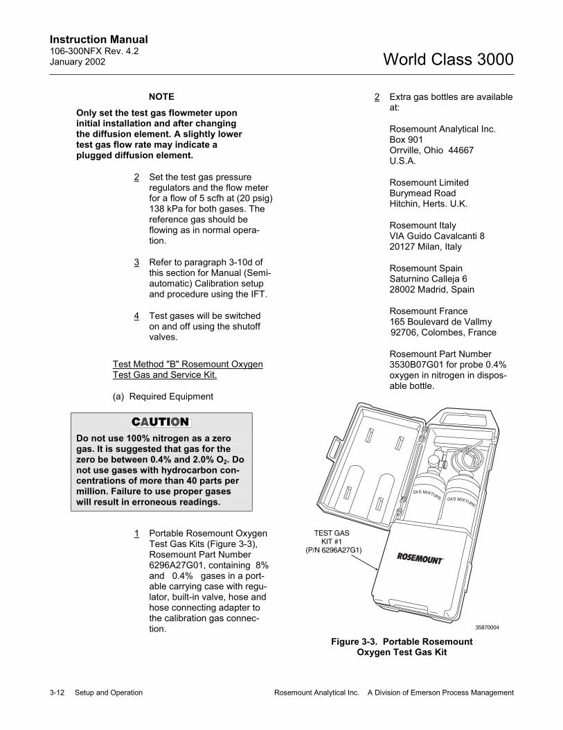
Instruction Manual106-300NFX Rev. 4.2January 2002
3-12 Setup and Operation Rosemount Analytical Inc. A Division of Emerson Process Management
World Class 3000
NOTEOnly set the test gas flowmeter uponinitial installation and after changingthe diffusion element. A slightly lowertest gas flow rate may indicate aplugged diffusion element.
2 Set the test gas pressureregulators and the flow meterfor a flow of 5 scfh at (20 psig)138 kPa for both gases. Thereference gas should beflowing as in normal opera-tion.
3 Refer to paragraph 3-10d ofthis section for Manual (Semi-automatic) Calibration setupand procedure using the IFT.
4 Test gases will be switchedon and off using the shutoffvalves.
Test Method "B" Rosemount OxygenTest Gas and Service Kit.
(a) Required Equipment
Do not use 100% nitrogen as a zerogas. It is suggested that gas for thezero be between 0.4% and 2.0% O2. Donot use gases with hydrocarbon con-centrations of more than 40 parts permillion. Failure to use proper gaseswill result in erroneous readings.
1 Portable Rosemount OxygenTest Gas Kits (Figure 3-3),Rosemount Part Number6296A27G01, containing 8%and 0.4% gases in a port-able carrying case with regu-lator, built-in valve, hose andhose connecting adapter tothe calibration gas connec-tion.
2 Extra gas bottles are availableat:
Rosemount Analytical Inc.Box 901Orrville, Ohio 44667U.S.A.
Rosemount LimitedBurymead RoadHitchin, Herts. U.K.
Rosemount ItalyVIA Guido Cavalcanti 820127 Milan, Italy
Rosemount SpainSaturnino Calleja 628002 Madrid, Spain
Rosemount France165 Boulevard de Vallmy92706, Colombes, France
Rosemount Part Number3530B07G01 for probe 0.4%oxygen in nitrogen in dispos-able bottle.
TEST GASKIT #1
(P/N 6296A27G1)
35870004
Figure 3-3. Portable RosemountOxygen Test Gas Kit

Instruction Manual106-300NFX Rev. 4.2
January 2002
Rosemount Analytical Inc. A Division of Emerson Process Management Setup and Operation 3-13
World Class 3000
Rosemount Part Number3530B07G02 for probe 8%oxygen in nitrogen in dispos-able bottle.
3 A check valve is required atthe probe (between the cali-bration fitting and the gas line)to prevent the migration ofprocess gases down the cali-bration gas line.
(b) Calibration with a Portable Rose-mount Oxygen Test Gases Kit.
1 A typical portable test calibra-tion setup is shown in Figure3-4. For Manual (semiauto-matic) calibration, remove capplug from the calibrate-in-place fitting. The cap plugmust be retained to seal thisfitting after calibration is com-plete; failure to do so mayrender the probe useless ifthe system pressure is slightlynegative. The reference gasshould be flowing as in normaloperation.
CALIBRATEIN PLACE
CONNECTION
PUSHBUTTONREGULATOR
WITH CONTENTSGAGE - SET 5 SCFH
CHECKVALVE
NOTE: PROBE CALIBRATION GASFITTING HAS A SEAL CAP THATMUST BE IN PLACE EXCEPTDURING CALIBRATION.
REFERENCEAIR
CONNECTION
TEST HOSECONNECTSTO CHECKVALVE
0.4%O2
8.0%O2
23800010
Figure 3-4. Typical Portable Test Calibration Setup
2 Refer to paragraph 3-10d ofthis section for Manual (Semi-automatic) Calibration setupand procedure using the IFT.
3 Screw the push button regu-lator with contents gage on tothe test gas of choice and in-ject the test gas by openingthe valve. Gas is on continu-ously when the valve isopened.
d. Manual (Semiautomatic) CalibrationProcedure
Consult Safety Data Sheet 1M03296before performing any work on theCENELEC approved IFT 3000.
The following procedure relates to an op-erator initiated calibration selected at theIFT by pressing the CAL key. The calibra-tion is manually performed by the operatorupon data queues from the IFT. Any systemwithout an MPS 3000 Multiprobe Test GasSequencer must follow these steps.
1. Press SETUP to display the SETUPmenu. Select PROBE CALIBRATIONsub-menu. Ensure that Auto Cal is dis-abled. Set the cursor on Auto Cal.Press ENTER. Set Auto Cal to NO ifnot already done.
2. Press the CAL key. Select PERFORMCALIBRATION sub-menu. "Press EN-TER to start Manual Calibration" willappear on the LCD display. Press EN-TER to start. Follow the data queues.Refer to Table 3-4. CALIBRATE O2Menu.

Instruction Manual106-300NFX Rev. 4.2January 2002
3-14 Setup and Operation Rosemount Analytical Inc. A Division of Emerson Process Management
World Class 3000
e. Fully Automatic Calibration
Consult Safety Data Sheet 1M03296before performing any work on theCENELEC approved IFT 3000.
1. Test Gases for Fully Automatic Cali-bration. For fully automatic calibration,an MPS 3000 Multiprobe Test Gas Se-quencer is required as well as the twotypes of test gas.
Do not use 100% nitrogen as a zerogas. It is suggested that gas for thezero be between 0.4% and 2.0% O2. Donot use gases with hydrocarbon con-centrations of more than 40 parts permillion. Failure to use proper gaseswill result in erroneous readings.
Two tanks of precision calibration gasmixtures. Recommended calibrationgases are nominally 0.4 percent and8.0 percent oxygen in nitrogen.
A typical automatic calibration systemis shown in Figure 3-5.
2. Fully Automatic Calibration Setup. Inorder for the IFT system to calibrateautomatically, the following parametersfrom the CALIBRATE sub-menu in theIFT have to be entered. Refer to Table3-5. SETUP Sub-Menu.
(a) Auto Cal YES/NO
Set to YES
(b) Output Tracks YES/NO
Set as desired to configure analogoutput tracking.
(c) Cal Intrvl XD XH
Set the desired time between cali-brations in number of days andhours. (1 year max.)
(d) Next Cal. XD XH
Displays the time left to the start ofthe next calibration. Set the de-sired time until the start of the nextcalibration. If nothing is enteredhere, the unit will automaticallyenter the cal intrvl and count downfrom that. (1 year max.)
(e) Gas Time 0:00
Set the amount of time for the testgasses to be turned on in numberof minutes and seconds, allowenough time for signal values tostabilize.
(f) Purge Time 0:00
Set the amount of time for the gaslines to clear in number of minutesand seconds.
(g) Abort Time 0:00
Set the amount of time allowedbetween key functions before thecalibration procedure is aborted innumber of minutes and seconds.
(h) Res Alarm _____
Set the desired resistance alarmbetween 50 - 10000 ohms.
Once these parameters have been set,the system will initiate calibration with-out operator intervention as set by theCAL INTVL parameter.
3. Manually Initiated Fully Automatic Cali-bration Procedure. The following pro-cedure relates to an operator initiatedcalibration, either by a remote switch(CAL INIT on interconnect board) orselected at the IFT by pressing theCAL key using an MPS 3000 Multi-probe Gas Sequencer.

Instruction Manual106-300NFX Rev. 4.2
January 2002
Rosemount Analytical Inc. A Division of Emerson Process Management Setup and Operation 3-15
World Class 3000
(a) Press SETUP to display theSETUP sub-menu. Select Calibra-tion. Ensure that Auto Cal is en-abled. Set the cursor on Auto Cal.Press ENTER. Set Auto Cal toYES if not already done.
(b) Press the CAL key. Select PerformCalibration. "Press ENTER to startAutomatic Calibration" will appearon the LCD display. Press ENTERto start. Refer to Table 3-4. CALI-BRATE O2 Sub-Menu.
PROBE(END VIEW)
IFT
TEST GAS
CHECKVALVE
PROBESIGNAL CONNECTIONS
MPS-IFTSIGNALCONNECTIONS
MPS
INSTRUMENTAIR IN
NOTE: 1. THE MPS CAN BE USED WITH UPTO FOUR PROBES. ONLY ONE PROBECAN BE CALIBRATED AT A TIME.PROBE CALIBRATIONS MUST BESCHEDULED IN MULTIPLE PROBEAPPLICATIONS.
REFERENCEAIR
HPS
730014
TEST GAS 1(HIGH O )2
TEST GAS 2(LOW O )2
2. HPS OPTION SHOWN.
Figure 3-5. Typical Automatic Calibration System

Instruction Manual106-300NFX Rev. 4.2January 2002
3-16 Setup and Operation Rosemount Analytical Inc. A Division of Emerson Process Management
World Class 3000

Instruction Manual106-300NFX Rev. 4.2
January 2002
Rosemount Analytical Inc. A Division of Emerson Process Management LDP Operation 4-1
World Class 3000
SECTION 4LDP OPERATION
Consult Safety Data Sheet 1M03296before performing any work on theCENELEC approved IFT 3000.
4-1 OVERVIEW
Ensure that the oxygen analyzer, heater powersupply (if included with the system), and intelli-gent field transmitter have been properly con-nected. It is important to check that groundingand screening of terminations are correctlymade to prevent the introduction of groundloops. The IFT is equipped with noise suppres-sion circuitry on the power supply and signal in-put lines. Proper grounding at installation willensure accuracy of function.
This section of the manual deals with operatorcontrols and displays available for the IFTequipped with LDP and four membrane keys.
Operating instructions for the GUI equipped IFTare included in Section 3.
Any procedures not associated with normal op-erations are included in Section 2, Installation,or Section 5, Troubleshooting.
ENTERSEL
34990019
6
5
CALTGHTGL
2
3
4
1
8
7
Figure 4-1. IFT with LDP Front Panel
4-2 IFT WITH LDP FRONT PANEL CONTROLSAND INDICATORS (Figure 4-1.)
Fig. 4-1IndexNo.
Control/LED Description
1 LEDDisplay
Indicates current O2 or testgas value.
2 CAL Calibration in progressindicator light.
3 TGH High test gas indicator light.High test gas is being used incalibration process.
4 TGL Low test gas indicator light.Low test gas is being used incalibration process.
5 ENTER The ENTER key is used toinitiate calibration or select atest gas parameter to change.
6 The increase key is used toincrease the value of the testgas parameters.
7 The decrease key is used todecrease the value of the testgas parameters.
8 SEL The select key is used toscroll through the list ofparameters.
4-3 LDP DISPLAYS
Consult Safety Data Sheet 1M03296before performing any work on theCENELEC approved IFT 3000.
The LDP equipped IFT contains four selectabledisplays. The displays are selected by pressingthe SEL key. The display is advanced onceeach time the SEL key is depressed and con-tinually scrolls. The only parameters which theoperator is permitted to change change are H(high test gas) and L (low test gas). When a pa-rameter is to be changed, press the ENTER
Instruction Manual106-300NFX Rev. 4.2January 2002
4-2 LDP Operation Rosemount Analytical Inc. A Division of Emerson Process Management
World Class 3000
key. To change the parameter, the increase anddecrease arrows are depressed until the propervalue is displayed. Depress the ENTER key toaccept the new value, or the SEL key to abortthe change. The four displays are as follows:
a. O2
The O2 selection will display the O2 value onthe LED display when ENTER key is de-pressed.
b. H
The high test gas display allows the value ofthe high test gas parameter to be changedfor calibration purposes.
c. L
The low test gas display allows the value ofthe low test gas parameter to be changedfor calibration purposes.
d. CAL
The calibration selection allows the operatorto initiate the calibration process when EN-TER key is depressed.
4-4 LDP DEFAULTS
The LDP equipped IFT is programmed at thefactory with the defaults indicated in Table 4-1.For a description of the defaults refer to Table3-4. SETUP Sub-Menu.
4-5 CALIBRATION
a. Overview
The LDP equipped IFT is configured at thefactory for manual (semiautomatic) calibra-
tion. Calibration must be manually initiated.Information on test gases and hardware re-quirements may be found in paragraph3-10, Calibration.
b. Manual Calibration
The following procedures relate to an op-erator initiated calibration. The calibration ismanually performed by the operator upondata queues from the IFT. Any system with-out an MPS 3000 multiprobe test gas se-quencer must follow these steps.
Consult Safety Data Sheet 1M03296before performing any work on theCENELEC approved IFT 3000.
1. Press the SEL key until CAL is shownon the LED display.
2. Press ENTER. The CAL light is nowon. Turn on high test gas.
3. Press ENTER. The TGH light is nowflashing.
4. When the value shown on the LEDdisplay has stabilized, press ENTER.Turn off high test gas.
5. Turn on low test gas. Press ENTER.The TGL light is now flashing.
6. When the value shown on the LEDdisplay has stabilized, press ENTER.
7. Turn off low test gas. Press ENTER.
8. All indicator lights are off. Calibrationcomplete.

Instruction Manual106-300NFX Rev. 4.2
January 2002
Rosemount Analytical Inc. A Division of Emerson Process Management LDP Operation 4-3
World Class 3000
Table 4-1. LDP Defaults
PARAMETER DEFAULT PARAMETER DEFAULT
Probe CalibrationHigh GasLow GasAuto CalOutput TracksCal IntervalNext CalGas TimePurge TimeResistance Alarm
8.0%0.4%NOYESOFFDisabled5:00 MIN5:00 MIN1000 ohms
Efficiency Calc.Enable CalcK1 ValueK2 ValueK3 Value
Relay Outputs (K1)Event 1Event 2Event 3
NO0.00.00.0
Heater FailCal. FailINCAL
O2 CalculationSlopeConstantHtr Set Point
____(value from calibration)____(value from calibration)736°C (when implemented)
Relay Outputs (2)Event 1Event 2Event 3
LO O2OFFOFF
O2 AlarmsHI AlarmLO AlarmAlarm DB
30%0.3%0.0%
Analog OutputSourceAout Type
O2 0-10%4-20mA

Instruction Manual106-300NFX Rev. 4.2January 2002
4-4 LDP Operation Rosemount Analytical Inc. A Division of Emerson Process Management
World Class 3000

Instruction Manual106-300NFX Rev. 4.2
January 2002
Rosemount Analytical Inc. A Division of Emerson Process Management Troubleshooting 5-1
World Class 3000
SECTION 5TROUBLESHOOTING
Consult Safety Data Sheet 1M03296before performing any work on theCENELEC approved IFT 3000.
Install all protective equipment coversand safety ground leads after trouble-shooting. Failure to install covers andground leads could result in seriousinjury or death.
5-1 OVERVIEW
The system troubleshooting describes how toidentify and isolate faults which may develop inthe Oxygen Analyzer System. Refer to Probe,IFT, HPS, and MPS Appendices.
5-2 SPECIAL TROUBLESHOOTING NOTES
a. Grounding
It is essential that adequate grounding pre-cautions are taken when the system is be-ing installed. A very thorough check mustbe made at both the probe and electronicsto ensure that the grounding quality has notdegraded during fault finding. The systemprovides facilities for 100% effectivegrounding and the total elimination ofground loops.
b. Electrical Noise
The IFT has been designed to operate inthe type of environment normally found in aboiler room or control room. Noise suppres-sion circuits are employed on all field termi-nations and main inputs. When fault finding,the electrical noise being generated in theimmediate circuitry of a faulty system shouldbe evaluated. All cable shields must beconnected to earth.
c. Loose Integrated Circuits
The IFT uses a microprocessor and sup-porting integrated circuits. Should the elec-tronics unit receive rough handling duringinstallation in a location where it is sub-jected to severe vibration, an IntegratedCircuit (IC) could work loose. The fault find-ing guides in paragraph 5-3a. and TableE-2, Appendix EX, show the resulting vari-ety of failure modes. It is recommended thatall IC's be confirmed to be fully seated be-fore troubleshooting on the system begins.
d. Electrostatic Discharge
Electrostatic discharge can damage the IC'sused in the electronics unit. It is essentialbefore removing or handling the processorboard or the IC's used on it, that the userensure he/she is at ground potential.

Instruction Manual106-300NFX Rev. 4.2January 2002
5-2 Troubleshooting Rosemount Analytical Inc. A Division of Emerson Process Management
World Class 3000
5-3 SYSTEM TROUBLESHOOTING
The IFT provides system failure information withtwo different error message formats. The errormessages vary due to system configuration.Refer to Appendix EX, IFT 3000 Troubleshoot-ing.
a. GUI Equipped IFT
The status line of the GUI equipped IFT willdisplay one of ten conditions: OK, CAL(calibration), C Err (calibration error), H Err(heater error), TGLow (test gas low), HiO2(high O2 level), LoO2 (low O2 level), andR Hi (high resistance level), Off and PRBE.Refer to Table E-2, Appendix EX for addi-tional troubleshooting information on theGUI equipped IFT.
Consult Safety Data Sheet 1M03296before performing any work on theCENELEC approved IFT 3000.
1. OK - The system is operatingnormally.
2. CAL - The system is currentlyundergoing calibration.
3. C Err - An error was detected duringthe calibration process.
4. H Err - There is a fault within the heatersystem.
5. TGLow - There is no test gas pressure.
6. HiO2 - The O2 value is above the highalarm limit.
7. LoO2 - The O2 value is below the lowalarm limit.
8. R Hi - The cell resistance is above thehigh limit.
9. Off - The probe has been turned offbecause the IFT cannot control theheater temperature.
10. PRBE - The probe is disconnected,cold, or leads are reversed.

Instruction Manual106-300NFX Rev. 4.2
January 2002
Rosemount Analytical Inc. A Division of Emerson Process Management Return of Material 6-1
World Class 3000
SECTION 6RETURN OF MATERIAL
6-1 If factory repair of defective equipment is re-quired, proceed as follows:
a. Secure a return authorization number froma Rosemount Analytical Sales Office orRepresentative before returning the equip-ment. Equipment must be returned withcomplete identification in accordance withRosemount instructions, or it will not be ac-cepted.
In no event will Rosemount be responsiblefor equipment returned without properauthorization and identification.
b. Carefully pack defective unit in a sturdy boxwith sufficient shock absorbing material toinsure that no additional damage will occurduring shipping.
c. In a cover letter, describe completely:
1. The symptoms from which it was de-termined that the equipment is faulty.
2. The environment in which the equip-ment has been operating (housing,weather, vibration, dust, etc.).
3. The site from which equipment wasremoved.
4. Whether warranty or nonwarrantyservice is requested.
5. Complete shipping instructions for re-turn of replacement or repaired equip-ment to you.
6. Reference the return authorizationnumber.
d. Enclose a cover letter and purchase orderand ship the defective equipment, accordingto instructions provided in Rosemount Re-turn Authorization, prepaid, to:
Rosemount Analytical Inc.RMR Department1201 N. Main StreetOrrville, Ohio 44667
If warranty service is requested, the defec-tive unit will be carefully inspected andtested at the factory. If failure was due toconditions listed in the standard Rosemountwarranty, the defective unit will be repairedor replaced at Rosemount's option, and anoperating unit will be returned to the cus-tomer in accordance with shipping instruc-tions furnished in the cover letter.
For equipment no longer under warranty,the equipment will be repaired at the factoryand returned as directed by your purchaseorder and shipping instructions.

Instruction Manual106-300NFX Rev. 4.2January 2002
6-2 Return of Material Rosemount Analytical Inc. A Division of Emerson Process Management
World Class 3000
Instruction Manual106-300NFX Rev. 4.2
January 2002
Rosemount Analytical Inc. A Division of Emerson Process Management Appendices 7-1
World Class 3000
SECTION 7APPENDICES
APPENDIX AX. WORLD CLASS 3000 OXYGEN ANALYZER PROBE (CENELEC APPROVED VERSION)
APPENDIX BX. HPS 3000 HEATER POWER SUPPLY FIELD MODULE (CENELEC APPROVED VERSION)
APPENDIX DX. MPS 3000 MULTIPROBE TEST GAS SEQUENCER
APPENDIX EX. IFT 3000 INTELLIGENT FIELD TRANSMITTER
APPENDIX JX. HART COMMUNICATOR MODEL 275D9E IFT 3000 APPLICATIONS

Instruction ManualAppendix AX Rev. 2.1February 1998
A-0 Appendices Rosemount Analytical Inc. A Division of Emerson Process Management
World Class 3000
DO
NO
TO
PEN
WHILE ENERGISE
D
SEE LABEL BEFORE
O
PE
NIN
G
1 2
3
4
5
6
7
8
9
10
1112
19780003
24
23
22
21
20
19
18
17
15
14
13
16
B
A
NOTES: 1.
2.
3.
SEE SAFETY DATA SHEET 1M03226FOR A LIST OF PROBE REPAIRS ACUSTOMER MAY MAKE.
ITEM B , CALIBRATION GAS TUBE, FITSINTO HOLE A WHEN PROBE ISASSEMBLED.
NOT ALL PARTS SHOWN ARE AVAILABLEFOR PURCHASE SEPARATELY. FOR A LISTOF AVAILABLE PARTS, SEE TABLE A-3.
APPENDIX AX
Figure A-1. Oxygen Analyzer (Probe - CENELEC Approved) Exploded View
1. Snubber Diffuser 2. Retainer Screw 3. Calibration Tube
Insert 4. Retainer 5. Cell and Flange
Assembly 6. Corrugated Seal 7. Probe Tube and Junction
Box Assembly 8. Tube Nut, Ferrule, and
Tie-Rap 9. Hose Clamp 10. Label 11. Terminal Block 12. Label Attaching Hardware
Mounting Plate 13. Gas Connection 14. Terminal Block Marker 15. Seal Cap 16. Terminal Block 17. V-Strut Assembly
18. Terminal Block Screw 19. Ground Wires 20. Junction Box Gasket 21. Hose 22. Junction Box Lid 23. Probe Head Hardware 24. Cover Setscrew

Instruction ManualAppendix AX Rev. 2.1
February 1998
Rosemount Analytical Inc. A Division of Emerson Process Management Appendices A-1
World Class 3000
APPENDIX AX, REV. 2.1WORLD CLASS 3000 OXYGEN ANALYZER PROBE
(CENELEC APPROVED VERSION)
DESCRIPTION
Consult Safety Data Sheet 1M03226 forprobe safety related information.
A-1 OXYGEN ANALYZER (PROBE) – GENERAL
The CENELEC approved Oxygen Analyzer(Probe), Figure A-1 consists of three componentgroups (Figure A-2): probe exterior, inner probe,and probe head. Specifications for theCENELEC approved probe are contained inTable A-1.
A-2 PROBE ASSEMBLY EXTERIOR
Primary probe exterior components include aflange-mounted zirconium oxide cell, mountedon a tube assembly and protected by a flamearrestor and snubber diffuser.
DO
NO
TO
PEN
WH
ILE ENERG
ISE
D
S
EELABEL BEFO
RE
O
PE
NIN
G
PROBE
EXTERIOR
PROBE
INTERIOR
JUNCTION
BOX
19780004
Figure A-2. Main Probe Components
a. Cell and Flange Assembly
The primary component in the cell andflange assembly, Figure A-3, is a yttria-stabilized zirconium oxide cell. It creates anelectrical signal when theoxygen level onone side is out of balance with the oxygenlevel on the other side. This signal is pro-portional to the difference in oxygen levels.
b. Probe Tube Assembly
Screws and a retainer ring secure the celland flange assembly, Figure A-3, to theprobe tube assembly. When in place, thecell is inside the tube. The retainer ring ishigh temperature chrome plated to preventgalling and seizing. It is also coated withanti-seize compound to help avoid seizing.
730009
PROBETUBE
CORRUGATEDSEAL
RETAINER
CALIBRATIONTUBE INSERT
CELL ANDFLANGE
ASSEMBLY
Figure A-3. Cell and Tube Assemblies

Instruction ManualAppendix AX Rev. 2.1February 1998
A-2 Appendices Rosemount Analytical Inc. A Division of Emerson Process Management
World Class 3000
Table A-1. Specifications for Oxygen Analyzing Equipment 1, 2
Probe lengths, nominal ................................................... 457 mm (18 in.), 0,91 m (3 ft), 1,83 m (6 ft),depending on duct dimensions.
Temperature limits in process measurement area ......... 10-704°C (50-1300°F)Standard/current output .................................................. 4-20 mA dc signal (factory set)O2 indication (Digital display and analog output) ............ 0.1% O2 or ±3% of reading, whichever is
greater using Rosemount test gases.Cell speed of response ................................................... 1 millisecondSystem speed of response ............................................. less than 3 seconds (amplifier output)Resolution sensitivity ...................................................... 0.01% O2 transmitted signalProbe reference air flow.................................................. 56,6 L/hr (2 scfh) clean, dry, instrument quality
air (20.95% O2)Calibration gas mixtures ................................................. Rosemount Hagan Test Gas Kit Part No.
6296A27G01 contains 0.4% O2N2Nominal and 8% O2N2 Nominal
Calibration gas flow......................................................... 141,6 L/hr (5 scfh)Probe heater power supply............................................. 44 Vac from HPS 3000HPS 3000 power requirement ........................................ 225 VAAmbient operating temperature of probe junction box.... 0°-150°C (32°-302°F)HPS 3000 ambient operating temperature ..................... 0°-50°C (32°-120°F)Approximate shipping weights:
457 mm (18 in.) package...................................... 30 kg (66 lbs)0,91 m (3 ft) package............................................ 40 kg (88 lbs)1,83 m (6 ft) package............................................ 55 kg (121 lbs)
1 All static performance characteristics are with operating variables constant.2 Temperatures over 537°C (1000°F) may affect the ease of field cell replaceability.
The tube assembly includes a flange whichmates with a stack-mounted flange. Studson the stack flange make installation easy.There is also a tube to carry calibration gasfrom the probe head to the process side ofthe cell during calibration.
c. Flame Arrestor Diffuser
The flame arrestor diffuser, Figure A-4,protects the cell from heavy particles andisolates the cell from changes in tempera-ture. The assembly consists of a flame arre-stor and a snubber diffuser. The flamearrestor and diffuser thread onto the probetube. Pin spanner wrenches (probe disas-
sembly kit 1L03825G01) are applied toholes in the diffusion element hub to re-move or install the diffuser assembly.
The Flame Arrestor and Flame Arre-stor Hub are among the critical com-ponents in this type of protection(Flameproof Enclosure Type D'). SeeSafety Data Sheet 1M03226.
Systems that use an abrasive shield requirea special flame arrestor and diffuser as-sembly with a hub that is grooved to accepttwo dust seal gaskets.

Instruction ManualAppendix AX Rev. 2.1
February 1998
Rosemount Analytical Inc. A Division of Emerson Process Management Appendices A-3
World Class 3000
PINWRENCH
SNUBBERDIFFUSOR
19780006
Figure A-4. Flame Arrestor Diffuser Assembly
d. Cell General
The components which make up the cell aremachined to close tolerances and assem-bled with care to provide accurate oxygenmeasurements. Any replacement requiresattention to detail and care in assembly toprovide good results.
Failure to follow the instructions inthis manual could cause danger topersonnel and equipment. Read andfollow instructions in this manualcarefully.
The oxygen probe includes an inner elec-trode for the cell assembly. It consists of aplatinum pad and a platinum/inconel com-posite wire which produces the cell constantoffset voltage described in the Nernst equa-tion.
With this pad and wire, the constant will bebetween -10 to +15 mV. The cell constant isnoted in the calibration data sheet suppliedwith each probe.
Every probe should be calibrated andchecked after repair or replacement of cell,pad and wire, heater, or thermocouple, orafter disassembly of the probe.
HEATER
REFERENCEGAS TUBE
V-STRUT
P00005A
CERAMICSUPPORT TUBE
Figure A-5. Inner Probe Assembly
A-3 INNER PROBE ASSEMBLY
The inner probe assembly, Figure A-5, consistsof six main parts:
a. Ceramic support rod with four holes runningthrough the length. The holes serve as in-sulated paths for the cell signal wire andthermocouple wires.
b. A heater that is helically wrapped on aquartz support cylinder and insulated.
c. A chromel-alumel thermocouple which actsas the sensing element for the temperaturecontroller. (Not visible in Figure A-4; locatedwithin ceramic support rod.)
d. A platinum screen pad which forms electri-cal contact with the inner electrode of theelectrochemical cell. (Not visible in FigureA-5; located at end of ceramic support rod.)The pad is attached to an inconel wirewhich carries the signal to the terminal strip.
e. A V-strut assembly to give support to theinner probe assembly.
f. A tube to carry reference gas to the cell.
Turn to Maintenance and Service for repair pro-cedures for probe components.

Instruction ManualAppendix AX Rev. 2.1February 1998
A-4 Appendices Rosemount Analytical Inc. A Division of Emerson Process Management
World Class 3000
TERMINALSTRIP
REFERENCEGAS FITTING
P00006A
CALIBRATIONGAS FITTING
VENT
Figure A-6. Junction Box
A-4 JUNCTION BOX
The junction box, Figure A-6, is positioned atthe external end of the probe and contains aterminal strip for electrical connections and fit-tings for reference and calibration gases. Fit-tings are for 0.250 inch stainless steel tubing.The calibration fitting has a seal cap which mustremain in place except during calibration. Atubing fitting is also supplied to be used with thecalibration gas supply during calibration.
If the calibration gas bottles will be permanentlyhooked up to the probe, an optional check valveis recommended to prevent condensation of fluegas in the calibration lines.
During operation and calibration, reference gasis supplied through the reference gas fitting tothe reference side of the cell. This gives thesystem a known quantity of oxygen with whichto compare the oxygen level in the process gas.Unlike the non-CENELEC World Class 3000Probe, reference air must be used in conjunc-tion with the CENELEC World Class 3000probe.
During calibration, two gases of different knownoxygen concentrations are injected one at atime through the calibration gas fitting. Stainlesssteel tubing delivers this gas to the process sideof the cell. In a healthy cell, the difference inoxygen pressure from the process side to thereference side of the cell will cause a millivoltoutput proportional to the difference in oxygenlevels. The electronics unit can use the twomillivolt outputs caused by the two calibrationgases for either automatic or semi-automaticcalibration.
Do not attempt to remove a processgas sample through either gas fitting.Hot gases from the process woulddamage gas hoses in the probe head.
A-5 CABLE ASSEMBLY
Cable used to interconnect apparatus mustconform to the applicable codes of practice inthe country of installation (example: BS4345 inGreat Britain). Rosemount can supply a cable(P/N 1U03066) which is fitted with EExd IICbarrier glands. The installer should note that onsome earlier versions of the cable, the glands,although EExd IIC approved, are not of the bar-rier gland variety. These glands should not beused. Rosemount can supply a gland kit for thecorresponding barrier gland (P/N 1U03066G07).Each kit contains one pair of glands. TheRosemount supplied cable is a 7 conductorcable to connect the probe to the HPS 3000,and to connect the HPS 3000 to the electronicspackage. Standard length for this cable is 6 m(20 ft), but lengths up to 45 m (150 ft) are avail-able. The 7 conductors include 1 shielded pairof wires for the cell millivolt signal, 1 shieldedpair of type K wires for the thermocouple, and 3individual 16-gauge wires for the heater and forground. All metal shields are isolated at theprobe end and connect by drain wires to groundat the electronics. The cable is suitable for usein ambient temperatures up to 90°C (194°F).

Instruction ManualAppendix AX Rev. 2.1
February 1998
Rosemount Analytical Inc. A Division of Emerson Process Management Appendices A-5
World Class 3000
DR
AIN
AA
VIE
W‘A
-A'
EL
EC
TC
AB
LE
CA
LG
AS
RE
FG
AS
GR
OU
PN
OT
E
A B
3F
T
6F
T
GA
ST
UB
EP
ICK
-UP
GA
ST
UB
EP
ICK
-UP
GR
OU
PN
OT
E
MA
T'L
CO
DE
PA
RT
NU
MB
ER
OR
RE
FD
WG
A GR
OU
P
G01
G02
G03
BC
PA
RT
SL
IST
PA
RT
SL
IST
UN
ITS
:IN
CH
ES
NO
TE
DE
FIN
ER
SIZ
E-R
EF
ER
EN
CE
INF
OR
MA
TIO
NIT
EM
01
02
03
04
05
06
07
PA
RT
NA
ME
CE
NE
LE
C
WO
RL
DC
LA
SS
30
00
GA
SP
ICK
-UP
GA
SP
ICK
-UP
GA
SP
ICK
-UP
AN
ALY
ZE
RH
OU
SIN
G
MT
GH
AR
DW
AR
E
AS
SY
HA
RD
WA
RE
DW
G
DW
G
DW
G
DW
G
DW
G
DW
G
DW
G
)P
RO
BE
18
"
)3
FT
)6
FT
)9
FT
1U
05
68
0G
20
45
07
C2
6G
07
45
07
C2
6G
08
45
07
C2
6G
09
1M
03
24
1H
01
45
07
C5
1H
03
1L
03
82
6G
02
1 1111
1 1111
1 1111
NO
TE
S:
RE
FE
RE
NC
EA
IRS
UP
PLY
CO
NN
EC
TIO
NB
ITE
TY
PE
FIT
TIN
G(P
AR
KE
RC
PI)
FO
R0
.25
0O
.D.
TU
BIN
G.
2S
CF
HA
T3
PS
IGM
AX
.C
LE
AN
DR
YA
IRR
EQ
UIR
ED
.F
ITT
ING
ISL
OC
AT
ED
ON
FA
RS
IDE
.C
AL
IBR
AT
ION
AN
DP
UR
GE
GA
SC
ON
NE
CT
ION
.B
ITE
TY
PE
FIT
TIN
G(P
AR
KE
RC
PI)
10
SC
FH
AT
32
PS
IGM
AX
.C
AL
IBR
AT
ION
GA
SR
EQ
UIR
ED
.L
AG
TO
EN
SU
RE
GA
ST
EM
PE
RA
TU
RE
DO
ES
NO
TG
OB
EL
OW
DE
WP
OIN
TO
RE
XC
EE
D5
00
C(9
32
F).
oo
INS
TA
LL
WIT
HA
NA
LY
ZE
RIN
AV
ER
TIC
AL
LY
DO
WN
WA
RD
DIR
EC
TIO
NO
NLY.
FL
UE
GA
SO
PE
RA
TIN
GT
EM
PE
RA
TU
RE
RA
NG
E6
50
-9
80
C(1
20
0-
18
00
F).
oo
oo
RE
CO
MM
EN
DE
D2
IN.
TH
KIN
SU
LA
TIO
N.
TH
ER
MA
LC
ON
DU
CT
IVIT
YK
EQ
UA
LS
0.5
FO
RIN
SU
LA
TIO
N.
DIM
EN
SIO
NS
AR
EIN
MIL
LIM
ET
ER
SW
ITH
INC
HE
SIN
PA
RE
NT
HE
SE
SU
NL
ES
SO
TH
ER
WIS
EIN
DIC
AT
ED
.
1.
2.
3.
4.
5.
6.
7.
16
5.1
0(6
.50
)R
EF
DIR
EC
TIO
NO
FF
LO
W
82
5.5
(32
.5)
RE
FO
N3
FT
AN
D6
FT
PIC
K-U
P(4
50
7C
26
G0
7A
ND
G0
8)
17
27
.2(6
8)
RE
FO
N9
FT
PIC
K-U
P(4
50
7C
26
G0
9)
94
0(3
7)
RE
FO
N3
FT
(45
07
C2
6G
07
)1
85
0(7
3)
RE
FO
N6
FT
(45
07
C2
6G
08
)2
77
0(1
09
)R
EF
ON
9F
T(4
50
7C
26
G0
9)
58
4.0
(23
.0)
69
3.6
7(2
7.3
1)
CL
EA
RA
NC
ER
EQ
UIR
ED
FO
RP
RO
BE
INS
ER
TIO
NA
ND
RE
MO
VA
LCA
BL
E
FL
AN
GE
GA
SK
ET
AN
DH
AR
DW
AR
E
GA
SK
ET
AN
DH
AR
DW
AR
EW
EL
DB
YC
US
TO
ME
R
10
0(3
.93
)
19780009
Figure A-7. Bypass Probe Option

Instruction ManualAppendix AX Rev. 2.1February 1998
A-6 Appendices Rosemount Analytical Inc. A Division of Emerson Process Management
World Class 3000
A-6 PROBE OPTIONS
a. Abrasive Shield Assembly
The abrasive shield assembly (IB-106-300NX Series, Figure 2-1) is a stainless-steel tube that surrounds the probe assem-bly. The shield protects the probe againstparticle abrasion and corrosive condensa-tions, provides a guide for ease of insertion,and acts as a probe position support, espe-cially for longer length probes. The abrasiveshield assembly uses a modified flame ar-restor and diffuser filled with dual dust sealpacking.
b. Bypass Probe Options
For processes where the flue gas exceedsthe maximum allowable temperature of
704°C (1300°F) a bypass sensor packagecan be employed. The bypass system usesan 18 inch probe mounted externally on thestack or duct. The process or exhaustgases are directed out to the probe throughan extension/return duct. The bypass ar-rangement does not require the use of aspi-ration air and the gas which flows past theprobe is returned to the stack or duct.
The bypass probe package is normally usedfor process temperatures of 704°C (1300°F)to 980°C (1800°F). "Inconel 600" has anoperating range up to 980°C (1800°F).
Overall dimensions and mounting details ofthe bypass system are shown in Figure A-7.
TROUBLESHOOTING
Before conducting any work on theprobe, consult probe Safety DataSheet 1M03226.
Install all protective equipment coversand safety ground leads after trouble-shooting. Failure to replace coversand ground leads could result in seri-ous injury or death.
A-7 OVERVIEW
The probe troubleshooting section describeshow to identify and isolate operating faultswhich may develop in the probe assembly.
A-8 PROBE TROUBLESHOOTING
a. Probe Faults
The three symptoms of probe failure are:
1. The system does not respond tochanges in the oxygen concentration.
2. The system responds to oxygenchanges but does not give the correctindication.
3. The system does not give an accept-able indication of the value of the oxy-gen test gas being applied duringcalibration.
b. Table A-2 provides a guide to fault findingfor the above symptoms.
c. Figure A-8 and Figure A-9 provide an alter-nate approach to finding probe relatedproblems.

Instruction ManualAppendix AX Rev. 2.1
February 1998
Rosemount Analytical Inc. A Division of Emerson Process Management Appendices A-7
World Class 3000
Table A-2. Fault Finding
SYMPTOM CHECK FAULT REMEDY
1. No response tooxygen concentration change when:
Heater is cold andTC mV output is less than setpoint.
Thermocouple continuity Thermocouple failure Replace thermocoupleor return probe toRosemount.
Heater cold resistance tobe 11 ohm - 14 ohm
Heater failure Replace heater or returnprobe to Rosemount.
Triac O/P to heater Failure of electronics Check HPS andelectronics package.
Heater is hot andT/C mV output is at setpoint ±0.2 mV.
Recorder chart Recorder failure See Recorder Instruc-tion Manual.
Cell mV input to electron-ics and cell mV at probejunction box
No cell mV at probe whentest gas applied
Replace cell or returnprobe to Rosemount.
Probe cell mV OK but noinput to electronics
Check out cableconnection.
Cell mV satisfactory bothat probe junction box andinput to electronics -failure of electronics
Check electronicspackage.
2. System responds to oxygen concentration changes but does not give correct indication.
Good response, withincorrect indication.
Recorder or remoteindicator
Calibration error Recalibrate recorder orindicator, referenceRecorder InstructionManual.
System calibration Calibration error Recalibrate system.
Probe mounting andcondition of duct
Air ingress into duct Stop air leaks or resiteprobe.
Cell mV input toelectronics
Failure of electronics Check electronicspackage.
3. Probe does not give accurate indication ofapplied test gas.
Test gas input port Blocked port Clean port.
Ceramic diffusion element Diffusion element cracked,broken, or missing
Replace diffusionelement.

Instruction ManualAppendix AX Rev. 2.1February 1998
A-8 Appendices Rosemount Analytical Inc. A Division of Emerson Process Management
World Class 3000
?
CHECK CELL MVTERMINALS 1 & 2IN PROBEJUNCTION BOX
DOES CELL MVCORRESPOND WITHEXPECTED OCONCENTRATION
2
MEANS LOW O ORCOMBUSTIBLES IS GASSTREAM. RECONFIRM THE
CONCENTRATION
2
O2
CHECK ELECTRONICSAND CELL MV I/PTO ELECTRONICS.
CHECK CABLE
PULL PROBE AND CHECKFOR CRACKED DIFFUSIONELEMENT OR CRACKEDCELL
REPLACE CELL
YES
OK
NO - ZERO ORVERY LOW
TOO HIGH
NO - HIGH
?
?
CHECK CELLRESISTANCE
ZERO
LOWCHECK THE CRIMP WHICH CONNECTSTHE INCONEL WIRE TO ITS EXTENSIONWIRE IN THE PROBE JUNCTION BOX.
?
?
CHECK THAT PLATINUM WIRE ISMAKING CONTACT WITH CELL. IFTHE PAD ASSEMBLY CAN BEPUSHED FORWARD THEN THEREWAS POOR CONTACT
DISASSEMBLE ANDCHECK FOR BROKENCERAMICS RODS,SPRING, OR OTHERRESTRICTIONS.REPLACE
CELL
BADCONTACT
BADCONTACT
REPLACECRIMP
GOODCONTACT
GOODCONTACT
P00009B
Figure A-8. Flowchart of Probe Related Problems, #1

Instruction ManualAppendix AX Rev. 2.1
February 1998
Rosemount Analytical Inc. A Division of Emerson Process Management Appendices A-9
World Class 3000
P00009A
CHECK HEATER FUSE AND TRIACOUTPUT TO HEATER.
HEATER MAY BE DEAD. THERMOCOUPLEMAY BE READIN STACK TEMPERATURE.
?
HEATER, THERMOCOUPLE ANDCONTROL ARE SATISFACTORY.REFER TO HEATER POWERSUPPLY TROUBLESHOOTING.
IS IT HIGHER,LOWER, ORZERO?
?LOWERHIGHER
ZERO
YES
ISHEATER
THERMOCOUPLECIRCUITOPEN?
YES
REPLACE CONTACTAND THERMOCOUPLE
ASSEMBLY
ALLOW ADDITIONAL TIMEFOR TEMP CONTROL TOSETTLE.
COLD JUNCTION TEMPAT ELECTRONICS BOXMAY BE MUCH LOWERTHAN 25°C (77°F).
2.
1.
NO
NO
CHECK THERMOCOUPLE MVAT TERMINALS 3 AND 4 INPROBE JUNCTION BOX.
IS IT ABOUT SETPOINT MV ±0,2 MV?[THE MV MEASURED IS NOT YET COLD.JUNCTION COMPENSATED, SO IT WILLVARY BY -0,022 MV PER DEGREEFAHRENHEIT RISE IN THETEMPERATURE OF THE ELECTRONICSBOX LOCATION. NORMAL IS SETPOINTMV AT 25°C (77 ).]°F
3. CONFIRM MV VALUE ONELECTRONICS UNIT. IF OK,RESOLVE DIFFERENCEBETWEEN VOLTMETER ANDELECTRONICS.
1.
CHECK HEATER CONDITION.TURN OFF POWER. RESISTANCEBETWEEN TERMINALS 7 AND 8SHOULD BE 11-14 OHMS.RESISTANCE BETWEEN TERMINALS6 AND 7 AND 6 AND 8 SHOULDBE OPEN CIRCUIT. IF FAILED,REPLACE STRUT.
2.
Figure A-9. Flowchart of Probe Related Problems, #2

Instruction ManualAppendix AX Rev. 2.1February 1998
A-10 Appendices Rosemount Analytical Inc. A Division of Emerson Process Management
World Class 3000
MAINTENANCE AND SERVICE
NOTE!Upon completing installation, make sure that the probe is turned on and operating prior tofiring up the combustion process. Damage can result from having a cold probe exposed tothe process gases.
During outages, and if possible, leave all probes running to prevent condensation and prema-ture aging from thermal cycling.
If the ducts will be washed down during outage, MAKE SURE to power down the probes andremove them from the wash area.
Before carrying out any service ormaintenance on the probe, consultSafety Data Sheet 1M03226.
When working on this equipment onthe laboratory bench, be aware thatthe probe, probe tube, and flame arre-stor hub can be hot [up to 370°C(698°F)] in the region of the probeheater.
Install all protective equipment coversand safety ground leads after equip-ment repair or service. Failure to in-stall covers and ground leads couldresult in serious injury or death.
A-9 OVERVIEW
This section describes routine maintenance ofthe oxygen analyzer probe. Spare parts referredto are available from Rosemount. Probe disas-sembly kit 1LO3825G01 contains the requiredspanner and hex wrenches. Refer to Replace-ment Parts of this appendix for part numbersand ordering information.
A-10 PROBE RECALIBRATION
The oxygen analyzer system should be cali-brated when commissioned. Under normalcircumstances the probe will not require fre-quent calibration. When calibration is required,follow the procedure described in the InstructionBulletin applicable to your electronics package.
A-11 CELL REPLACEMENT
This paragraph covers oxygen sensing cellreplacement. Do not attempt to replace thecell until all other possibilities for poor per-formance have been considered. If cell re-placement is needed, order cellreplacement kit, Table A-3.
The cell replacement kit contains a cell andflange assembly, corrugated seal, calibra-tion tube insert, setscrews, socket head capscrews, and anti-seize compound. Itemsare carefully packaged to preserve precisesurface finishes. Do not remove items frompackaging until they are ready to be used.Spanner wrenches and hex wrenchesneeded for this procedure are part of anavailable special tools kit, Table A-3.

Instruction ManualAppendix AX Rev. 2.1
February 1998
Rosemount Analytical Inc. A Division of Emerson Process Management Appendices A-11
World Class 3000
Before carrying out this procedure,consult Safety Data Sheet 1M03226.
Wear heat resistant gloves and cloth-ing to remove probe from stack.Normal operating temperatures ofdiffuser and vee deflector areapproximately 316° to 427°C (600° to800°F). They could cause severeburns.
Do not remove cell unless it is certainthat replacement is needed. Removalmay damage cell and platinum pad. Gothrough complete troubleshootingprocedure to make sure cell needsreplacement before removing it.
a. Follow the power down procedure outlinedin Safety Data Sheet 1M03226 and the offi-cial "Codes of Practice" for your country ofinstallation. Shut off and disconnect refer-ence gas and calibration gas supplies fromprobe junction box, Figure A-10. Wearingheat resistant gloves and clothing, removeprobe assembly from stack carefully andallow to cool to room temperature. Do notattempt to work on unit until it has cooled toa comfortable working temperature.
b. The vee deflector is an option used with theceramic diffuser. Figure A-11 shows a probewith a snubber diffuser. If the probe has thevee deflector, remove vee deflector and hubsetscrews and remove vee deflector. Usespanner wrenches from probe disassemblytools kit, Table A-3, to turn hub free fromprobe tube. If applicable, inspect optionalceramic diffusion element. If damaged, re-place element.
CALIBRATIONGAS FITTING
GROUND WIRE(GREEN)
GROUND WIRE(GREEN)
CELL EXTENSIONWIRE (ORANGE)
THERMOCOUPLE WIRE (+)(YELLOW CHROMEL)
THERMOCOUPLE WIRE (-)(RED ALUMEL)
HEATER WIRES(BLACK)
INTERNAL EARTHINGTERMINAL (TERMINAL 6)
EXTERNALEARTHING
HARDWARE
CABLE
REFERENCEGAS FITTING
P00010A
Figure A-10. Cell Wiring Installation

Instruction ManualAppendix AX Rev. 2.1February 1998
A-12 Appendices Rosemount Analytical Inc. A Division of Emerson Process Management
World Class 3000
c. Loosen 4 socket head screws from retainer.Pull off retainer and calibration tube in-sert, Figure A-12. Discard calibration tubeinsert.
d. Press the cell flange against the probe endflange and twist through 90° in both theclockwise and counterclockwise directions.This breaks the bond between the cell andthe platinum pad. Once the bond is broken,remove the cell.
e. View the platinum pad through the probeend flange. Reform the platinum pad into ashape to match the cell electrode by gath-ering in any loose strands which may havebecome untidy. This may be done with asmall flat screwdriver.
f. Remove and discard corrugated seal. Cleanmating faces of probe tube and retainer.Remove burrs and raised surfaces withblock of wood and crocus cloth.
g. Rub one or two drops of anti-seize com-pound #3535B53G01 between fingers.Smear on both sides of corrugated seal.
h. Install new calibration tube insert in retainer,with the short arm of the tube insert pene-trating the calibration gas passage in theouter ring of the retainer. Assemble retainer,cell and flange assembly, corrugated seal,
PROBETUBE PIN SPANNER
WRENCH
SNUBBERDIFFUSOR 19780017
Figure A-11. Removal of Snubber Diffuser
and probe tube. Make sure the calibrationtube insert lines up with the calibration gaspassage in each component. Firmly seatthe calibration tube insert in the assembly.Apply a small amount of anti-seize com-pound to screw threads and use screws tosecure assembly. Torque to 4 N·m(55 in-lbs).
i. To install snubber diffuser, apply anti-seizecompound to threads of probe tube, FigureA-11, and snubber diffuser. Reinstall dif-fuser on probe tube. Using pin spannerwrenches, torque to 14 N·m (10 ft-lbs).
j. If using the optional vee deflector and ce-ramic hub, apply anti-seize compound tothreads of probe end flange, hub, andsetscrews. Reinstall hub on probe tube.Using pin spanner wrenches, torque to14 N·m (10 ft-lbs). Reinstall vee deflector,orienting apex toward gas flow. Secure withsetscrews and anti-seize compound.Torque to 2.8 N·m (25-in-lbs). Secure hubretaining setscrew.
k. On systems equipped with an abrasiveshield, install dust seal gaskets, with joints180° apart.
730010
PROBEEND
FLANGE
PROBE TUBE(NOT INCLUDED KIT)
CORRUGATEDSEAL
CELL ENDFLANGE ASSEMBLY
RETAINER
SOCKETHEAD CAP
SCREW
CALIBRATIONTUBE INSERT
CALIBRATIONTUBE PASSAGE
Figure A-12. Cell Replacement Kit

Instruction ManualAppendix AX Rev. 2.1
February 1998
Rosemount Analytical Inc. A Division of Emerson Process Management Appendices A-13
World Class 3000
l. Reinstall probe and gasket on stack flange.If there is an abrasive shield in the stack,make sure dust seal gaskets are in place asthey enter 15° reducing cone.
m. Consult Safety Data Sheet 1M03226 thenturn power on to electronics and monitorthermocouple output. It should stabilize at29.3 mV ±0.2 mV. Set reference air flow at56.6 L/hr (2 scfh). After probe stabilizes,calibrate probe per Instruction Bulletin ap-plicable to your electronics package. If newcomponents have been installed, repeatcalibration after 24 hours of operation.
A-12 CERAMIC DIFFUSION ELEMENTREPLACEMENT
NOTEThis refers to ceramic diffuser elementonly.
a. General
The diffusion element protects the cell fromparticles in process gases. It does not nor-mally need to be replaced because the veedeflector protects it from particulate erosion.In severe environments, the filter may bebroken or subject to excessive erosion. Ex-amine the ceramic diffusion element when-ever removing the probe for any purpose.Replace if damaged.
Damage to the ceramic diffusion elementmay become apparent during calibration.Compare probe response with previous re-sponse. A broken diffusion element willcause a slower response to calibration gas.
Hex wrenches needed to remove setscrewsand socket head screws in the followingprocedure are available as part of a ProbeDisassembly Kit, Table A-3.
Wear heat resistant gloves and cloth-ing to remove probe from stack.Normal operating temperatures ofdiffuser and vee deflector areapproximately 316° to 427°C (600° to800°F). They can cause severe burns.
Before carrying out this procedure,consult Safety Data Sheet 1M03226.
Do not remove cell unless it is certainthat replacement is necessary. Cellcannot be removed for inspectionwithout damaging it.
b. Replacement Procedure
1. Follow the power down procedure out-lined in Safety Data Sheet 1M03226and the official "Codes of Practice" foryour country of installation. Disconnectcable conductors and remove cable,Figure A-10. Shut off and disconnectreference gas and calibration gas sup-plies from probe junction box. Wearingheat resistant gloves and clothing,carefully remove probe assembly fromstack.
2. Loosen setscrews, Figure A-13, usinghex wrench from Probe DisassemblyKit, Table A-3 and remove vee deflec-tor. Inspect setscrews. If damaged, re-place with stainless setscrews coatedwith anti-seize compound.
3. On systems equipped with abrasiveshield, remove dual dust seal gaskets.

Instruction ManualAppendix AX Rev. 2.1February 1998
A-14 Appendices Rosemount Analytical Inc. A Division of Emerson Process Management
World Class 3000
4. Use spanner wrenches from ProbeDisassembly Kit, Table A-3, to turn hubfree from retainer.
5. Put hub in vise. Break out old ceramicdiffusion element with chisel along ce-ment line and 9.5 mm (3/8 in.) pinpunch through cement port.
6. Break out remaining ceramic diffusionelement by tapping lightly around hubwith hammer. Clean grooves withpointed tool if necessary.
7. Replace ceramic diffusion element,using replacement kit in Table A-3.This consists of a diffusion element,cement, setscrews, anti-seize com-pound and instructions.
8. Test fit replacement ceramic diffusionelement to be sure seat is clean.
Do not get cement on ceramic diffu-sion element except where it touchesthe hub. Any cement on ceramic diffu-sion element blocks airflow throughelement. Wiping wet cement off of ce-ramic only forces cement into pores.Also do not get any cement onto theflame arrestor element.
9. Thoroughly mix cement and insert tipof squeeze bottle into cement port. Tiltbottle and squeeze while simultane-ously turning ceramic diffusion elementinto seat. Do not get any cement onupper part of ceramic diffusion ele-ment. Ensure complete penetration ofcement around 3 grooves in hub. Ce-ment should extrude from oppositehole. Wipe excess material back intoholes and wipe top fillet of cement toform a uniform fillet. (A Q-Tip is usefulfor this.) Clean any excess cementfrom hub with water.
21240026
HUB
RETAINER
PINWRENCH
OPTIONAL CERAMICDIFFUSION ELEMENT
SETSCREW
VEEDEFLECTOR
CEMENTFILLET
CEMENTPORT
Figure A-13. Removal of Optional CeramicDiffuser and Vee Deflector
10. Allow filter to dry at room temperatureovernight or 1 to 2 hours at 93°C(200°F).
11. Wipe a heavy layer of anti-seize com-pound onto the threads and matingsurfaces of the flame arrestor, diffusionhub, and probe tube.
12. Assemble flame arrestor and diffusionhub with two pin spanner wrenches.Torque to 14 N·m (10 ft-lbs). Securewith hub retaining setscrew.
13. On systems equipped with abrasiveshield, install dust seal gaskets withjoints 180° apart.
14. Reinstall vee deflector, orienting apextoward gas flow. Apply anti-seize com-pound to setscrews and tighten withhex wrench.
15. Reinstall probe on stack flange.

Instruction ManualAppendix AX Rev. 2.1
February 1998
Rosemount Analytical Inc. A Division of Emerson Process Management Appendices A-15
World Class 3000
16. Consult Safety Data Sheet 1M03226then turn power on to electronics andmonitor thermocouple output. It shouldstabilize at 29.3 mV ±0.2 mV. Calibrateprobe per Instruction Bulletin applica-ble to your electronics package.
A-13 REPLACEMENT OF CONTACT ANDTHERMOCOUPLE ASSEMBLY
Use heat resistant gloves and clothingwhen removing probe junction boxand inner probe assembly. Do not at-tempt to work on these componentsuntil they have cooled to room tem-perature. Probe components can be ashot as 800°C (1500°F). This can causesevere burns.
Before carrying this procedure, con-sult Safety Data Sheet 1M03226.
a. Follow the cell removal procedure in para-graph A-3, steps a, b, c, and d. Using heatresistant gloves and clothing, remove coversetscrew (24, Figure A-1) and junction boxlid (23). Squeezing tabs on hose clamps,remove hoses from inner probe assembly,Figure A-14. Remove 4 screws which se-cure the inner probe assembly to the junc-tion box. Disconnect all inner probeassembly wires from the terminal block(Figure A-10). Pull inner probe assemblyfree from junction box. Set on bench andallow to cool to room temperature.
b. Use a pencil to mark locations of springclips on ceramic rod, Figure A-15.
c. Pry or squeeze tabs on spring clips, andpull contact and thermocouple assembly outof probe assembly. Retain spring clips andspring; replace if damaged.
P00013A
PROBEJUNCTION BOX
HOSECLAMP
BACKPLATEMOUNTING
SCREW
HOSE
Figure A-14 Probe Junction Box MechanicalConnections
P00014A
STRUT
HEATERSCREWS
GUIDELOOPS
SPRINGCLIP
BACKPLATEMOUNTINGHARDWARE
CONTACT ANDTHERMOCOUPLE
ASSEMBLY
Figure A-15. Inner Probe Replacement (Heater,V-Strut, and Backplate Assembly)

Instruction ManualAppendix AX Rev. 2.1February 1998
A-16 Appendices Rosemount Analytical Inc. A Division of Emerson Process Management
World Class 3000
Be very careful when handling contactand thermocouple assembly. The ce-ramic rod in this assembly is fragile.
d. While very carefully handling new contactand thermocouple assembly, lay old as-sembly next to new one. Transfer pencilmarks to new rod. Throw away old contactand thermocouple assembly.
e. Carefully guide new contact and thermo-couple assembly through V-strut assemblyleaf spring (3, Figure A-16), spring (8),spring clips (9) (held open by squeezingtabs), tube supports and heater support un-til spring clip reaches pencil mark.
f. Slide assembled inner probe assembly intojunction box and probe tube. To align cali-bration gas tube with corresponding hole inbackplate (A, B, Figure A-1) insert scriberthrough hole in backplate and into calibra-tion gas tube. Secure with screws. Reinstallhoses.
NOTEThe letter "A" is stamped inside thejunction box close to the calibrationtube. The calibration tube may fallover towards the opposite side. If ithas, bring it back towards the letter"A" before inserting the inner probeassembly. Also note that there aregrooves cut in the heater plates that fitover the calibration gas tube. Insertinner probe assembly gently to avoidkinking the calibration gas tube.
g. Connect color-coded wires to proper termi-nals as shown in Figure A-10. Rosemountrecommends connecting the thermocouplewires directly to the terminal strip. This isbecause the junction of different metals atthe wires and lugs and at the lugs and theterminal strip could act as additional ther-mocouple junctions. This could produce avoltage that would affect the thermocoupleoutput signal.
Do not bend wires closer than 6.4 mm (1/4in.) from end of ceramic rod. Dress wires sothey do not touch sides of probe junctionbox.
h. Reinstall the cell per paragraph A-11, stepsf, g, h, i, j, and k.
i. Consult Safety Data Sheet 1M03226 thenpower up system. Monitor thermocoupleoutput. It should stabilize at setpoint mV±0.2 mV. Recalibrate probe per InstructionBulletin applicable to your electronics pack-age.
A-14 REPLACEMENT OF HEATER, V-STRUTAND BACKPLATE ASSEMBLY (InnerProbe Assembly; Includes Contact andThermocouple Assembly)
Figure A-17 is a cross-sectional view of theCENELEC approved oxygen analyzer (probe).Use Figure A-17 and the following procedure toreplace heater, v-strut, and backplate assembly.
Before carrying out this procedure,consult Safety Data Sheet 1M03226.
Use heat resistant gloves and clothingwhen removing probe junction boxand inner probe assembly. Do not at-tempt to work on these componentsuntil they have cooled to room tem-perature. Probe components can be ashot as 800°C (1500°F). This can causesevere burns.
a. Follow the cell removal procedure in para-graph A-3, steps a, b, c, and d. Using heatresistant gloves and clothing, remove coversetscrew (24, Figure A-1) and junction boxlid (23). Squeezing tabs on hose clamps,remove hoses from inner probe assembly,Figure A-13. Remove 4 screws which se-cure the inner probe assembly to the junc-tion box. Disconnect all inner probeassembly wires from the terminal block(Figure A-10). Pull inner probe assemblyfree from junction box. Set on bench andallow to cool to room temperature.

Instruction ManualAppendix AX Rev. 2.1
February 1998
Rosemount Analytical Inc. A Division of Emerson Process Management Appendices A-17
World Class 3000
1 2 34
5
91011
8
73 6 POOO15A
1. Heater Ceramic Rod 2. Contact and Thermocouple
Assembly 3. Leaf Spring
4. Extension Wire 5. Ring Lug 6. Connector 7. Backplate
8. Spring 9. Spring Clip 10. Strut 11. Heater
Figure A-16. Heater, Strut, and Backplate Assembly (Inner Probe Assembly)
NOTENot all parts shown are available for purchase separately. For a list of available parts,see Table A-3.
2 11
13
3 61 8 9 74 5
10
19780022
12
1. Snubber Diffuser 2. Calibration Tube Insert 3. Socket Head Cap Screw
0.25 In.-28 x 0.63 (16 mm) 4. Cell and Flange Assembly
5. Corrugated Seal 6. Probe Tube Assembly 7. Gasket 8. Cover Head Assembly 9. Hose Clamp
10. Heater Strut 11. Retainer 12. Junction Box Setscrew 13. Flame Arrestor Hub Setscrew
Figure A-17. Oxygen Analyzer (Probe), Cross-Sectional View

Instruction ManualAppendix AX Rev. 2.1February 1998
A-18 Appendices Rosemount Analytical Inc. A Division of Emerson Process Management
World Class 3000
b. Slide new assembled inner probe assemblyinto junction box and probe tube. To aligncalibration gas tube with corresponding holein backplate (A, B, Figure A-1), insertscriber through hole in backplate and intocalibration gas tube. Secure with screws.Reinstall hoses.
NOTEThe letter "A" is stamped inside thejunction box close to the calibrationtube. The calibration tube may fallover towards the opposite side. If ithas, bring it back towards the letter"A" before inserting the inner probeassembly. Also note that there aregrooves cut in the heater plates that fitover the calibration gas tube. Insertinner probe assembly gently to avoidkinking the calibration gas tube.
c. Connect color-coded wires to proper termi-nals as shown in Figure A-10. Rosemount
recommends connecting the thermocouplewires directly to the terminal strip. This isbecause the junction of different metals atthe wires and lugs and at the lugs and theterminal strip could act as additional ther-mocouple junctions. This could produce avoltage that would affect the thermocoupleoutput signal.
Do not bend wires closer than 6.4 mm(1/4 in.) from end of ceramic rod. Dresswires so they do not touch sides of probejunction box.
d. Reinstall the cell per paragraph A-3, stepsf, g, h, i, j, and k.
e. Consult Safety Data Sheet 1M03226, thenpower up system. Monitor thermocoupleoutput. It should stabilize at setpoint mV±0.2 mV. Recalibrate probe per InstructionBulletin applicable to your electronicspackage.

Instruction ManualAppendix AX Rev. 2.1
February 1998
Rosemount Analytical Inc. A Division of Emerson Process Management Appendices A-19
World Class 3000
REPLACEMENT PARTS
Table A-3. Replacement Parts for Probe
FIGURE andINDEX No.
PARTNUMBER DESCRIPTION
A-1, 13 3D39149G061 1U03066G07V-Strut Assembly (18 in.)A-1, 13 3D39149G071 V-Strut Assembly (3 ft)A-1, 13 3D39149G081 V-Strut Assembly (6 ft)A-16, 2 3534B56G042 Contact and Thermocouple Assembly (18 in.)A-16, 2 3534B56G052 Contact and Thermocouple Assembly (3 ft)A-16, 2 3534B56G062 Contact and Thermocouple Assembly (6 ft)
4847B61G19 Cell Replacement Kit (18 in.)4847B61G20 Cell Replacement Kit (3 ft)4847B61G21 Cell Replacement Kit (6ft)4847B61G24 Cell Replacement Kit (No Inconel and Platinum Pad Assembly)1U05677G01 Probe Disassembly Kit
A-11 1U05677G04 F/A Diffuser Hub Assembly (Snubber Diffuser)1U05677G06 F/A Diffuser Hub Assembly (For use with Abrasive Shield)6292A74G02 Ceramic Diffusion Element Replacement Kit1N04966H02 Abrasive Shield Assembly (3 ft)1N04966H03 Abrasive Shield Assembly (6 ft)1M03241H01 90° Elbow for Bypass
A-7, 2 4507C26G07 Bypass Gas Pickup Tube (3 ft)A-7, 3 4507C26G08 Bypass Gas Pickup Tube (6 ft)A-7, 4 4507C26G09 Bypass Gas Pickup Tube (9 ft)
263C152G01 Reference Gas Air Set771B635H01 Calibration Gas Rotameter1L03650H01 F/A Diffusion Hub Setscrew
IB-106-300NFX Instruction Bulletin (IFT)IB-106-300NCX Instruction Bulletin (CRE)IB-106-300NEX Instruction Bulletin (Upgrade - CENELEC Digital Electronics)1U03066G07 EExd Barrier Gland Kit (one pair of glands per kit)
1 V-Strut assembly includes contact and thermocouple assembly.2 Contact and thermocouple assembly includes platinum pad and inconel wire.
NOTEThe replacement parts listed above must be obtained only from the manufacturer orhis agent.

Instruction ManualAppendix AX Rev. 2.1February 1998
A-20 Appendices Rosemount Analytical Inc. A Division of Emerson Process Management
World Class 3000

Instruction ManualAppendix BX Rev. 1.2
January 1997
Rosemount Analytical Inc. A Division of Emerson Process Management Appendices B-1
World Class 3000
APPENDIX BX, REV. 1.2HPS 3000 HEATER POWER SUPPLY FIELD MODULE
(CENELEC APPROVED VERSION)
DESCRIPTION
Consult Safety Data Sheet 1M03243 forsafety related information.
B-1 DESCRIPTION
The Rosemount CENELEC approved HPS 3000Heater Power Supply Field Module (Figure B-1)acts as an interface between probe and elec-tronics and supplies power to the probe heater.The unit allows the use of probes with a numberof different electronics packages.
The CENELEC approved HPS 3000 is certifiedEExd IIC T6 to CENELEC standards EN50014and EN50018.
The heater power supply, Figure B-2, consistsof a motherboard, daughterboard, and a trans-former for supplying correct voltage to theprobe heater. The mother- and daughter-boards contain terminal strips for connectingprobe, electronics, and power supply.
The HPS is jumper configurable for 120, 220, or240 Vac.
If you reconfigure the equipment for aline voltage other than the one markedon the serial label, then you shouldchange the marking on the serial labelto state the new line voltage.
P00001B
Figure B-1. CENELEC Approved HPS 3000Heater Power Supply Field Module
B-2 THEORY OF OPERATION
The HPS 3000 Heater Power Supply may per-form slightly different functions, depending uponwhich electronics package with which it is used.Figure B-3 shows a functional block diagram ofthe unit. The HPS contains a transformer forconverting line voltage to 44 volts needed topower the probe heater. The relay can be usedto remotely turn the probe on or off manually.
A triac module is used to turn the heater on oroff, depending on probe temperature.
When used with the CRE 3000 Control RoomElectronics or IFT 3000 Intelligent Field Trans-mitter, the HPS uses a cold junction tempera-ture compensation feature. This allows for theuse of a less expensive cable between the HPSand CRE or HPS and IFT. The HPS and elec-tronics package can be located up to 364 m(1200 ft) apart.

Instruction ManualAppendix BX Rev. 1.2January 1997
B-2 Appendices Rosemount Analytical Inc. A Division of Emerson Process Management
World Class 3000
JM8
JM5JM4
JM2
JM
1
JM7
J7
J2
SCREW(2 PER COVER)
TERMINALCOVERS
(PROVIDED)
EXTERNALEARTHING
HARDWARE
INTERNALEARTHING
HARDWARE
TERMINALSTRIP(FROM PROBE)
P00002B
TERMINALSTRIP (FROMELECTRONICS)
TRANSFORMER
FRONT VIEW SIDE VIEW
Figure B-2. Heater Power Supply, Interior
Table B-1. Specifications for Heater Power Supply
Power Supply .............................................................................. 110/115/220 VAC ± 10% at 50/60 HzPower Requirement .................................................................... 200 VAHumidity Range........................................................................... 95% Relative HumidityAmbient Temperature Range...................................................... 0° to 60°C (32° to 140°F)Vibration ...................................................................................... 5 m/sec2, 10 to 500 xyz planeExternal Electrical Noise ............................................................. Minimum InterferenceInstallation Category (Overvoltage Category)............................. IEC 664 Category IICabling Distance Between HPS 3000 and Probe....................... Maximum 45 m (150 ft)Cabling Distance Between HPS 3000 and CRE 3000................ Maximum 364 m (1200 ft)Cabling Distance Between HPS 3000 and IFT 3000.................. Maximum 364 m (1200 ft)Approximate Shipping Weight..................................................... 20 kg (44 lbs)

Instruction ManualAppendix BX Rev. 1.2
January 1997
Rosemount Analytical Inc. A Division of Emerson Process Management Appendices B-3
World Class 3000
ZEROCROSSINGDETECTOR
TRIACRELAYTO HEATER
COLDJUNCTION
TEMP.PROBE TC
STACK TC
CELL
LINE
RELAY
TRIAC
AD590
PROBE TC
STACK TC
CELL MV
TRANSFORMER
FROMIFTOR
CRE
TOPROBE
730004
Figure B-3. Heater Power Supply Block Diagram
The standard cable, between probe and HPS, isthermocouple compensated. This prevents theadditional junctions between thermocouple andcablefrom producing a voltage which would af-fect the thermocouple output signal. A tem-perature sensor in the HPS monitors thetemperature at the junction and sends a voltagesignal to the CRE and IFT. The CRE and IFTuses this signal to compensate the probe ther-mocouple reading for the temperature at thejunction between the compensated anduncompensated cables.
In operation, when connected to the CRE 3000Control Room Electronics, line voltage passesthrough the relay (when on) and is convertedinto 44 volts by the transformer. If the probethermocouple indicates that the probe hasdropped below operating temperature, a signalfrom the CRE triggers the triac. The triac thensupplies voltage to the probe heater, warmingthe cell. Conversely, if the probe thermocoupleindicates that the probe heater has reached theupper limit of operating temperature, the CREdeactivates the triac, shutting off power to theheater.
B-3 CONNECTIONS TO NEW GENERATIONELECTRONICS (IFT 3000 AND CRE 3000)
Use the following information about input andoutput connections if your system includesCENELEC approved new generationelectronics.
a. Probe Thermocouple
PBTC+ and PBTC- (J3 pins 4 and 5, J8 pins3 and 4). This thermocouple provides feed-back from the probe heater to the electron-ics.
b. Stack Thermocouple (Optional)
STTC+ and STTC- (J2 pins 1 and 2, J9 pins5 and 6). The stack thermocouple is a ther-mocouple separate from the CENELEC ap-proved World Class 3000 Probe. It is usedto measure stack temperature.
c. AD590
AD590+ and AD590- (J8 pin 5, J8 pin 6).The AD590 is a temperature measuring de-vice used to measure temperature insidethe CENELEC approved Heater PowerSupply HPS 3000.
d. Zirconium Cell
PBMV+ and PBMV- (J3 pins 1 and 2, J8pins 1 and 2). The voltage signal from thezirconium cell.
e. Probe Heater
44 Vac output (J2 pins 4, 5, and 6). The 44Vac output to power the probe heater.

Instruction ManualAppendix BX Rev. 1.2January 1997
B-4 Appendices Rosemount Analytical Inc. A Division of Emerson Process Management
World Class 3000
f. TRIAC
TRIAC+ and TRIAC- (J9 pins 1 and 2). Thesignal by which the new generation elec-tronics controls the triac of Heater PowerSupply HPS 3000. By controlling this triac,the new generation electronics modulatesthe 44 V waveform to the probe heater.
g. Relay
Relay+ and Relay- (J9 pins 3 and 4). By ac-tivating or deactivating this relay, the newgeneration electronics can switch off orswitch on the 44 Vac from the Heater PowerSupply HPS 3000 to the probe heater. Thisfeature is jumper selectable (JM2).
h. Line Voltage
(J1 pins 1, 2, and 3). Jumper selectable(JM1, JM4, and JM5) for 120 Vac or220/240 Vac.
i. Shield (Cable Armour)
The cable armour, as well as providing me-chanical protection, acts as a shield. Thisshield is directly connected to the HeaterPower Supply HPS 3000 housing throughthe cable gland.
NOTEWhen using the HPS 3000 with an ex-isting electronics package, such asModels 218, 218A, or 225, the elec-tronics will not have the input/outputcapacity to support all of the functionsmentioned in this section. Refer to In-struction Bulletin IB-106-300NEX.
B-4 CONNECTION TO OLD GENERATIONELECTRONICS
Use the following information about input andoutput connections if your system does not in-clude CENELEC approved new generationdigital electronics:
a. Probe Thermocouple
PBTC+ and PBTC- (J3 pins 4 and 5, J8 pins3 and 4). This thermocouple provides feed-back from the probe heater to the electron-ics.
b. Stack Thermocouple
(Optional) STTC+ and STTC- (J2 pins 1 and2, J9 pins 5 and 6). The stack thermocoupleis a thermocouple separate from theWC3000 probe. It is used to measure stacktemperature.
c. Zirconium Cell
PBMV+ and PBMV- (J3 pins 1 and 2, J8pins 1 and 2). The voltage signal from thezirconium cell.
d. Probe Heater
44 Vac out (J2 pins 4, 5, and 6). This is the44 Vac output to power the probe heater.
e. Line Voltage Pins
This is a modulated 115 Vac from the oldgeneration electronics. Bridge rectifier(BR1) converts this modulated 115 Vac tothe TRIAC+ and TRIAC- low voltage signal.This signal controls the triac of the HeaterPower Supply HPS 3000. A modulated 44Vac is thus sent to the probe heater.
f. Shield (Optional)
(J8 pin 7.) The PBMV+/PBMV- and thePBTC+/PBTC- lines to the old generationelectronics may be shielded against electri-cal noise through these connections.
g. Shield (Cable Armour)
The cable armour, as well as providing me-chanical protection, acts as a shield. Thisshield is directly connected to the HeaterPower Supply HPS 3000 housing throughthe cable gland.

Instruction ManualAppendix BX Rev. 1.2
January 1997
Rosemount Analytical Inc. A Division of Emerson Process Management Appendices B-5
World Class 3000
TROUBLESHOOTING
Before carrying out any work on theCENELEC approved HPS 3000, consultSafety Data Sheet 1M03243.
Install all protective equipment coversand safety ground leads after trouble-shooting. Failure to replace coversand ground leads could result in seri-ous injury or death.
B-5 OVERVIEW
The HPS 3000 troubleshooting section de-scribes how to identify and isolate faults whichmay develop in the HPS 3000 assembly.
B-6 HPS 3000 TROUBLESHOOTING
The HPS 3000 troubleshooting may overlapwith the probe in use in the system. Faults ineither system may cause an error to be dis-played in the electronics package. Figure B-4and Figure B-5 provide troubleshooting informa-tion.

Instruction ManualAppendix BX Rev. 1.2January 1997
B-6 Appendices Rosemount Analytical Inc. A Division of Emerson Process Management
World Class 3000
HEATER DOES NOT HEATUP (DOES NOT INCREASEIN OUTPUT).
SET METER* FOR 50 VAC.PLACE PROBES ONTERMINAL BLOCK J2,“FROM PROBE”, PROBEHEATER.
METER INDICATESPULSATING NOMINAL44 VAC.
DISCONNECT POWER FROMHPS & PROBE ELECT. SETMETER ON RX1.
MEASURE RESISTANCE OFHEATER BY PLACINGPROBES ON TERMINALBLOCK J2, “FROM PROBE”,PROBE HEATER.
RESISTANCE MEASUREDSHOULD BE NOMINALLY12 OHMS.
SET METER TO 250 VAC.PLACE METER PROBES ONJ9, “FROM ELECTRONICS”,ANALOG HEATER.
METER SHOULD REGISTERA PULSATING NOMINAL115 VAC.
YES
DISCONNECT POWER TOHPS AND PROBEELECTRONICS. CHECKALL FOUR FUSES IN HPS.
FUSES BLOWN IN HPS.NO
NO
CHECK THAT LINE VOLTAGEIS CORRECT BY SELECTINGCORRECT JUMPERSACCORDING TO CHART ONINSIDE OF HPS COVER.
REPLACE BLOWN FUSES.
HEATER IS OPEN.REPLACE HEATER.
NO
YES YES
YES
NO
CHECK JUMPER JM2 ISINSTALLED.
IF FUSES OK, POSSIBLEPROBE ELECTRONICS TRIACFAILURE.
CHECK FUSES IN PROBEELECTRONICS.
POSSIBLE TRIAC FAILURE.REPLACE HPSMOTHERBOARD.
SYMPTOM
*SIMPSON MODEL 260 OR EQUIVALENT MULTIMETER. 34990015
Figure B-4. HPS Troubleshooting Flowchart, #1

Instruction ManualAppendix BX Rev. 1.2
January 1997
Rosemount Analytical Inc. A Division of Emerson Process Management Appendices B-7
World Class 3000
HEATER OVERHEATS.NOTE: ON INITIAL STARTUP THE
TEMPERATURE OF THE PROBE MAYOVERHEAT TO A NOMINAL TEMP OF800°C(480°F).
CHECK IF THE YELLOW WIRE IS CONNECTEDTO POSITIVE AND THE RED TO NEGATIVEON BOTH “FROM ELECTRONICS” AND “FROMPROBE” TERMINAL BLOCKS. (MODELS 218AND 225 ONLY)
SET METER* ON 250 VAC SCALE.
CHECK “FROM ELECTRONIC”, ANALOGHEATER TERMINALS IF THERE IS APULSATING NOMINAL 115 VAC ON J9.
CHECK “FROM PROBE”, TERMINALS ATPROBE HEATER IF THERE IS A PULSATINGNOMINAL 44 VOLTS ON J2.
CHECK PROBE ELECTRONICS SETPOINTHAS BEEN CHANGED ACCORDING TOAPPLICABLE ELECTRONICS PACKAGE IB.
SET METER* ON 50 VAC SCALE.
CHECK IF PROBE HEATER VOLTAGESELECTION JUMPER JM7 INSTALLED(REMOVE JM8).
CONNECT THE WIRINGACCORDING TO THEDECALS ON THE TERMINALCOVERS.
IF THE VOLTAGE ISCONSTANTLY ON, THENTHE TRIAC IN THE PROBEELECTRONICS IS SHORTED.
IF THE VOLTAGE ISCONSTANTLY ON, THENTHE TRIAC MODULE INTHE HPS IS SHORTED.
NO
NO
NO
YES
YES
YES
YES
SYMPTOM
*SIMPSON MODEL 260 OR EQUIVALENT MULTIMETER. 34990014
Figure B-5. HPS Troubleshooting Flowchart, #2

Instruction ManualAppendix BX Rev. 1.2January 1997
B-8 Appendices Rosemount Analytical Inc. A Division of Emerson Process Management
World Class 3000
MAINTENANCE AND SERVICE
Consult Safety Data Sheet 1M03243before performing any work on theCENELEC approved HPS 3000.
Install all protective equipment coversand safety ground leads after equip-ment repair or service. Failure to in-stall covers and ground leads couldresult in serious injury or death.
B-7 OVERVIEW
This section describes service and routinemaintenance of the HPS 3000 Heater PowerSupply Field Module. Replacement parts re-ferred to are available from Rosemount. Referto Replacement Parts of this appendix for partnumbers and ordering information.
B-8 FUSE REPLACEMENT
The heater power supply's motherboard (25,Figure B-6) contains four identical 5 amp fuses(24) (5 amp anti-surge, Type T to IEC127,ROSEMOUNT Part No. IL01293H02). To checkor replace a fuse, simply unscrew the fuseholder cap (23) with a flat head screwdriver andremove fuse. After checking or replacing a fuse,reinstall fuse holder cap.
B-9 TRANSFORMER REPLACEMENT
Consult Safety Data Sheet 1M03243before performing any work on theCENELEC approved HPS 3000.
a. Follow the power down procedure outlinedin safety data sheet 1M03243 and the offi-cial "Codes of Practice" for your country ofinstallation.
b. Loosen setscrew (13, Figure B-6) retainingHPS cover (14). Remove HPS cover.
c. Remove hex nut (2), flat washer (3), andhex head bolt (4) that retain transformer tomounting bracket.
d. Disconnect the 6-pin transformer wiringharness connector from J7 on the HPSmotherboard (25). Disconnect the 2-pinwiring harness connector from the jumperthat was selected to configure the HPS forthe proper voltage.
NOTEThe transformer connector is keyedmaking connection possible in onlyone direction.
e. Remove old toroidal transformer (11). Placenew transformer in position and reconnectwiring harness connectors as noted instep d.
f. Place insulating disc (10) (one on eitherside of transformer) and metal disc (12) ontransformer.
g. Tighten hex nut (2) and hex head bolt (4)only enough to firmly hold transformer inplace.
h. Reinstall HPS cover (14) and secure withsetscrew (13).
B-10 MOTHERBOARD REPLACEMENT.
Consult Safety Data Sheet 1M03243before performing any work on theCENELEC approved HPS 3000.
a. Follow the power down procedure outlinedin safety data sheet 1M03243 and the offi-cial "Codes of Practice" for your country ofinstallation.

Instruction ManualAppendix BX Rev. 1.2
January 1997
Rosemount Analytical Inc. A Division of Emerson Process Management Appendices B-9
World Class 3000
1
10
10
12
14
13
15
4
112-PINCONNECTOR
6-PINCONNECTOR
9
8
18
18
18
18
17
27
27
25
18
1817
2423
1817
26
16
22
22
28
20
21
7
17
17
6
16P00007
16
19
2
3
5
17
NOT ALL PARTS SHOWN ARE
AVAILABLE FOR PURCHASE
SEPARATELY. FOR A LIST OF
AVAILABLE PARTS, SEE
TABLE B-2.
NOTE:
Figure B-6. Heater Power Supply, Exploded View
1. HPS Housing 2. Hex Nut 3. Flat Washer 4. Hex Head Bolt 5. Transformer
Mounting Bracket 6. Screw 7. Lockwasher 8. Flat Washer 9. Hex Standoff 10. Insulating Disc 11. Toroidal Transformer 12. Metal Disc 13. Setscrew 14. HPS Cover 15. O-Ring Seal 16. Slotted Screw 17. Lockwasher 18. Flat Washer 19. Terminal Strip Cover
(Probe) 20. Terminal Strip Cover
(Electronics) 21. HPS Daughterboard
PCB 22. Hex Stand Off 23. Fuse Holder Cap 24. Fuse 25. HPS Motherboard
PCB 26. Hex Nut 27. Hex Standoff 28. Earthing Hardware

Instruction ManualAppendix BX Rev. 1.2January 1997
B-10 Appendices Rosemount Analytical Inc. A Division of Emerson Process Management
World Class 3000
b. Loosen setscrew (13) retaining HPS cover(14). Remove cover.
c. Disconnect transformer wiring harness con-nectors as described in the previous para-graph from motherboard (25).
d. Remove slotted screw (16), lockwasher(17), and flat washer (18) attaching terminalstrip covers (19) and (20). Remove terminalstrip covers.
e. Unplug ribbon cable from the receptacle onthe daughterboard (21). Take note of loca-tion of black and white wires connected topin 8 and pin 9 of terminal strip J8. Discon-nect these wires from J8.
f. Unscrew stand offs (22) on either side ofthe daughterboard. Remove daughterboard(21).
g. Unscrew four stand offs (22) that supportthe daughterboard.
h. Making a note of the location and color ofeach wire, disconnect wires from terminalstrip on HPS motherboard (25).
i. Remove hex nut (26), lockwasher (17), andflat washer (18) securing the HPS mother-board to the enclosure and transformermounting bracket (5).
j. Remove motherboard (25).
k. Position new motherboard on stand offs andreinstall hex nut, lockwasher, and flatwasher removed in step i.
l. Reconnect wires to terminal strip in posi-tions noted in step h. Cross check with wir-ing diagram shown on Figure 2-4 of themain text (IB-106-300NX Series).
m. Reinstall four stand offs removed in step g.Position daughterboard (21) on stand offsand reinstall stand offs removed in step f.
n. Plug ribbon cable back into receptacle ondaughterboard and reconnect black andwhite wires. The black wire goes to pin 8and the white to pin 9 of terminal block J8on daughter board. Reinstall terminal cov-ers.
o. Reconnect transformer wiring harness con-nectors to motherboard. Note that in anycase, the transformer's connector is keyedso that it can only be inserted one way.
p. Reinstall HPS cover (14) and secure withsetscrew (12).
B-11 DAUGHTERBOARD REPLACEMENT
Consult Safety Data Sheet 1M03243before performing any work on theCENELEC approved HPS 3000.
a. Follow the power down procedure outlinedin safety data sheet 1M03243 and the offi-cial "Codes of Practice" for your country ofinstallation.
b. Loosen setscrew (13, Figure B-6) retainingHPS cover (14). Remove cover.
c. Remove slotted screw (16), lockwasher(17), and flat washer (18) securing terminalstrip covers (19) and (20). Remove terminalstrip covers.
d. Making a note of the location and color ofeach wire, disconnect wires from the termi-nal strip on the daughterboard (21).
e. Unplug ribbon cable from receptacle ondaughterboard. Take note of location ofblack and white wires connected to pin 8and pin 9 of terminal strip J8. Disconnectthese wires from J8.
f. Unscrew two stand offs (22) from daughter-board. Remove daughterboard (21).

Instruction ManualAppendix BX Rev. 1.2
January 1997
Rosemount Analytical Inc. A Division of Emerson Process Management Appendices B-11
World Class 3000
g. Position new daughterboard on four standoffs (22) on motherboard (25). Reinstall thestand offs removed in step f.
h. Plug ribbon cable back into receptacle ondaughterboard and reconnect black andwhite wires. The black wire goes to pin 8and the white wire to pin 9 of terminal blockJ8 on daughterboard. Reinstall terminalcovers.
i. Reconnect wires to terminal strip in posi-tions noted in step d. Cross check with wir-ing diagram shown on Figure 2-4 of themain text (IB-106-300NX Series). Reinstallterminal covers.
j. Reinstall HPS cover (14) and secure withsetscrew (13).
REPLACEMENT PARTS
Table B-2. Replacement Parts for Heater Power Supply
FIGURE andINDEX No.
PARTNUMBER DESCRIPTION
B-1 1U05667G01 CENELEC HPS 3000 (120V)B-1 1U05667G03 CENELEC HPS 3000 (220V/240V)
B-6, 24 1L01293H02 Fuse 5A @ 250 Vac, anti-surge, case size; 5 x 20 mm, type Tto IEC127, Schurter
B-6, 25 3D39080G02 MotherboardB-6, 21 3D39078G01 DaughterboardB-6, 11 1M02961G05 Toroidal Transformer (120V/240V)
IB-106-300NEX Instruction Bulletin Upgrade and Digital ElectronicsIB-106-300NFX Instruction Bulletin (IFT)IB-106-300NCX Instruction Bulletin (CRE)
NOTEThe replacement parts listed above must be obtained only from the manufacturer orhis agent.

Instruction ManualAppendix BX Rev. 1.2January 1997
B-12 Appendices Rosemount Analytical Inc. A Division of Emerson Process Management
World Class 3000

Instruction ManualAppendix DX Rev. 2.1
January 1997
Rosemount Analytical Inc. A Division of Emerson Process Management Appendices D-1
World Class 3000
APPENDIX DX, REV. 2.1MPS 300 MULTIPROBE TEST GAS SEQUENCER
DESCRIPTION
The MPS 3000 Multiprobe Test GasSequencer must be installed in anon-hazardous, explosive freeenvironment.
NOTEZ-Purge option is available. Referencepage D-4.
D-1 DESCRIPTION
The Rosemount MPS 3000 Multiprobe Test GasSequencer provides automatic test gas se-quencing for up to four probes. The MPS routestest gas to the selected probe under control ofthe CRE, IFT, or digital electronics package.The electronics package can be prepro-grammed by the user for automatic periodic re-calibration, or manually initiated calibrationthrough the keypad on the front of the electron-ics package. The calibration parameters held inthe electronics package can be selected toautomatically update after each calibration.
The MPS is housed in a NEMA 4X (IP56) non-hazardous enclosure, Figure D-1.
NOTEA single multichannel MPS cannot beshared among a number of CRE elec-tronics.
The MPS, Figure D-2, consists of: an air pres-sure regulator, a terminal board, a flowmeterassembly (one for each probe, up to four perMPS), HI GAS solenoid, LO GAS solenoid, amanifold, and a power supply. Each flowmeterassembly contains a probe solenoid.
730005
Figure D-1. MPS 3000 MultiprobeTest Gas Sequencer
An optional Z-purge arrangement is available forhazardous area classification. See ApplicationData Bulletin AD 106-300B.
D-2 THEORY OF OPERATION
A typical automatic calibration setup is shown inFigure D-3. The MPS 3000 Multiprobe Test GasSequencer operates under the control of theCRE, IFT, or digital electronics package. Whenthe electronics package initializes automaticcalibration, the solenoid controlling the selectedprobe is energized. Next, the solenoid control-ling test gas 1 (high O2) energizes allowing testgas 1 to flow to that probe. After the probemeasures the oxygen concentration of test gas1, the gas solenoid is deenergized. An operatorselected time delay allows the gas to clear thesystem. Next, the solenoid controlling test gas 2(low O2) energizes and allows test gas 2 to flowto the probe. After the probe measures the oxy-gen concentration of test gas 2, the gas andprobe solenoids deenergize. The automaticcalibration is now complete for the probe se-lected.

Instruction ManualAppendix DX Rev. 2.1January 1997
D-2 Appendices Rosemount Analytical Inc. A Division of Emerson Process Management
World Class 3000
TUBE
35870005
ROTOMETER
POWERSUPPLY
REGULATOR
SOLENOID
MANIFOLD
HOSEADAPTER
TERMINATIONBOARD
CABLEGRIP
Figure D-2. Multiprobe Test Gas Sequencer, Interior
Table D-1. Specifications for Multiprobe Test Gas Sequencer
Power Supply ........................................................................................... 110/115/220 Vac ±10% at 50/60 HzPower Requirement ................................................................................. 15 VA (Watts)Electrical Classification ............................................................................ NEMA 4X (IP56)Humidity Range........................................................................................ 95% Relative HumidityAmbient Temperature Range................................................................... -30° to 71°C (-20° to 160°F)Vibration ................................................................................................... 5 m/sec2, 10 to 500 xyz planeExternal Electrical Noise .......................................................................... Minimum InterferenceInstallation Category (Overvoltage Category).......................................... IEC 664 Category IIPiping Distance Between MPS 3000 and Probe ..................................... Maximum 91 m (300 ft)Cabling Distance Between MPS 3000 and Electronics Package ............ Maximum 303 m (1000 ft)In Calibration Status Relay....................................................................... 48V max, 100 mA maxCabling Distance Between MPS 3000 and Status Relay Indicator ......... Maximum 303 m (1000 ft)Approximate Shipping Weight.................................................................. 16 kg (35 lbs)

Instruction ManualAppendix DX Rev. 2.1
January 1997
Rosemount Analytical Inc. A Division of Emerson Process Management Appendices D-3
World Class 3000
PROBE(END VIEW)
TEST GAS
CHECKVALVE
PROBESIGNAL CONNECTIONS
MPS-ELECTRONICSPACKAGE SIGNALCONNECTIONS
MPS
INSTRUMENTAIR IN
TEST GAS 1(HIGH O2)
TEST GAS 2(LOW O2)
ELECTRONICSPACKAGE
REFERENCEAIR
THE MPS CAN BE USED WITH UPTO FOUR PROBES AND FOURELECTRONIC PACKAGES. ONLYONE PROBE CAN BE CALIBRATEDAT A TIME. PROBE CALIBRATIONSMUST BE SCHEDULED IN MULTIPLEPROBE APPLICATIONS.
NOTE:
730006
Figure D-3. Typical Automatic Calibration System

Instruction ManualAppendix DX Rev. 2.1January 1997
D-4 Appendices Rosemount Analytical Inc. A Division of Emerson Process Management
World Class 3000N
OT
ES
:1.
MP
S 3
000
IS N
OT
CE
NE
LEC
CE
RT
IFIE
D,
BU
T T
HE
Z-P
UR
GE
OP
TIO
N I
S A
VA
ILA
BLE
.
2. D
IME
NS
ION
S A
RE
IN
MIL
LIM
ET
ER
SW
ITH
IN
CH
ES
IN
PA
RE
NT
HE
SE
S.
3
"BE
BC
O"
PU
RG
E W
AR
NIN
G N
OT
ICE
S
UP
PLI
ED
WIT
H B
EB
CO
UN
IT A
ND
TO
BE
IN
STA
LLE
D O
N M
PS
UN
ITA
S S
HO
WN
.
2
WIT
H E
LEC
TR
ON
ICS
DO
OR
CLO
SE
DT
IGH
TLY
. S
ET
AIR
RE
GU
LAT
OR
TO
65 P
A (
0.25
IN
. H
2O)
AS
IN
DIC
AT
ED
ON
RE
FE
RE
NC
E G
AU
GE
.
1C
US
TO
ME
R S
UP
PLI
ED
6.4
MM
(0.2
5 IN
.) O
D L
INE
.
5U
SE
KR
OY
LA
BE
L, B
LAC
K O
N C
LEA
R,
14 P
T. C
EN
TE
R L
AB
ELS
UN
DE
R
FIT
TIN
G H
OLE
S A
T D
ISTA
NC
E S
HO
WN
.
4T
O B
E C
ALL
ED
OU
T O
NS
HO
P O
RD
ER
.
6
CU
ST
OM
ER
SU
PP
LIE
D I
NS
TR
UM
EN
TQ
UA
LIT
Y C
OM
PR
ES
SE
D A
IR S
UP
PLY
M
US
T B
E E
QU
IPP
ED
WIT
H A
TA
MP
ER
-PR
OO
F R
EG
ULA
TO
R S
ET
T
O 3
4.48
kP
a (
5 P
SIG
) M
AX
IMU
M.
ALA
RM
NO
RM
ALL
Y C
LOS
ED
A
LAR
M N
OR
MA
LLY
OP
EN
ALA
RM
CO
MM
ON
61 2
5
4
25.4
0(1
.00)
25.4
0(1
.00)
3(2
PLC
S)
PA
RT
S L
IST
ITE
M01 02 03 04N
OT
E
PA
RT
NA
ME
MP
S A
SS
EM
BLY
Z-P
UR
GE
UN
ITZ
-PU
RG
E U
NIT
TU
BE
FIT
TIN
G
DW
GA
ML
AM
LD
WG
DE
FIN
ER
SIZ
E -
RE
FE
RE
NC
E I
NF
OR
MA
TIO
N
GR
OU
P N
OT
E
MA
T’L
CO
DE
PA
RT
NU
MB
ER
O
R R
EF
DW
G3D
3942
5GX
X1A
9847
4H01
1A98
474H
0277
1B87
0H05
GR
OU
P
G01
A/R 1 2
G02
A/R 1 2
) ) W
/O P
RE
SS
UR
E L
OS
S S
WIT
CH
) W
/ PR
ES
SU
RE
LO
SS
SW
ITC
H)
1/4"
TU
BE
TO
1/4
", S
.S.
PA
RT
S L
IST
UN
ITS
: IN
CH
ES
NO
TE
S:
DE
TAIL
S
WIT
CH
CO
NTA
CT
RA
TIN
G:
15A
- 1
25, 2
50, 4
80 V
AC
1/8
HP
125
VA
C1/
4 H
P 2
50 V
AC
CLA
SS
1, D
IV.
1 A
ND
2 G
R.
C A
ND
DC
SA
, F
M A
ND
UL
LIS
TE
D
ALA
RM
SW
ITC
HIN
G
"A"
CO
MN
ON
C
DR
ILL
AN
DTA
P T
HR
U F
OR
1/4"
NP
T (
2 P
LCS
)
76.2
0(3
.00)
63.5
0(2
.50)
38.1
0(1
.50)
19.0
5(0
.75)
LEF
T S
IDE
VIE
W L
AB
EL
OR
IEN
TAT
ION
AN
D H
OLE
PLA
CE
ME
NT
BE
BC
O M
OD
EL
Z-P
UR
GE
RE
AR
VIE
W
EN
CLO
SU
RE
PR
ES
SU
RE
IND
ICA
TO
R0-
125
PA
AT
MO
SP
HE
RIC
RE
F V
EN
T
RE
FE
RE
NC
EP
RE
SS
UR
E T
OD
IFF
ER
EN
TIA
LP
RE
SS
UR
ES
WIT
CH
(SE
E D
ETA
IL "
A")
12.7
(1/
2) C
ON
DU
IT W
IRIN
G I
NLE
T
EX
PLO
SIO
N P
RO
OF
PR
ES
SU
RE
LOS
S A
LAR
M S
WIT
CH
(U
SE
D O
N G
02 O
NLY
)
CA
LIB
RA
TIO
NS
CR
EW
VE
NT
UR
I O
RIF
ICE
RE
DU
ND
AN
T P
RE
SS
UR
EC
ON
TR
OL
VA
LVE
SY
ST
EM
RE
GU
LAT
OR
SY
ST
EM
SU
PP
LY
Figure D-4. MPS with Z-Purge

Instruction ManualAppendix DX Rev. 2.1
January 1997
Rosemount Analytical Inc. A Division of Emerson Process Management Appendices D-5
World Class 3000
TROUBLESHOOTING
D-3 OVERVIEW
This section describes troubleshooting for theMultiprobe Test Gas Sequencer. Additionaltroubleshooting information can be found in theInstruction Bulletin for the electronics package.
Install all protective equipment coversand safety ground leads after trouble-shooting. Failure to replace coversand ground leads could result in seri-ous injury or death.
D-4 TROUBLESHOOTING
Table D-2 provides a guide to fault finding fail-ures within the MPS. The flowchart in FigureD-5 provides an alternate approach to faultfinding MPS related problems.
Table D-2. Fault Finding
SYMPTOM CHECK FAULT REMEDY
1. Power to solenoid, test gas notreleased to probe.
Test gas
Solenoid
Insufficient test gas
Solenoid failure
Install new test gastanks.
Replace solenoid.
2. No power tosolenoid.
Power supply output Power supply failure Replace power supply.
Fuses in power supply Fuse blown Replace fuse.
Main power source Main power off Reestablish power.

Instruction ManualAppendix DX Rev. 2.1January 1997
D-6 Appendices Rosemount Analytical Inc. A Division of Emerson Process Management
World Class 3000
SOLENOID ISOPERATING NORMALLY.
SET METER* FOR 50 VDC.PLACE PROBES ONTERMINAL BLOCK J2, CALRET, AND J1 HI GAS.
SOLENOID IS RECEIVING24 VDC.
PLACE PROBES FROMMETER ON J11.
METER INDICATES24 VDC.
FUSES BLOWN IN MPS.
REPLACE BLOWN FUSES.
YES
NO
NO
NO
NO
NO
YES YES
YES
YES
YES
ENSURE THAT ASUFFICIENT SUPPLY OFTEST GAS IS AVAILABLE.
INSTALL NEW TEST GASBOTTLES.
NO
REPLACE SOLENOID.
REPLACE TERMINALBOARD.
PLACE PROBES FROMMETER ON J1, LINE 1, AND LINE 2. SET METERFOR 200 VAC.
METER INDICATES 110VAC AT J1.
CHECK MAIN POWERSOURCE.
REPLACE POWER SUPPLY.
CALL FOR FACTORYASSISTANCE.
*SIMPSON MODEL 260 OREQUIVALENT MULTIMETER.
P0002D
SYMPTOM
Figure D-5. MPS Troubleshooting Flowchart

Instruction ManualAppendix DX Rev. 2.1
January 1997
Rosemount Analytical Inc. A Division of Emerson Process Management Appendices D-7
World Class 3000
MAINTENANCE AND SERVICE
D-5 OVERVIEW
This section describes service and routinemaintenance of the MPS 3000 Multiprobe TestGas Sequencer. Replacement parts referred toare available from Rosemount. Refer to TableD-3 for part numbers and ordering information.
Install all protective equipment coversand safety ground leads after equip-ment repair or service. Failure to in-stall covers and ground leads couldresult in serious injury or death.
D-6 FUSE REPLACEMENT
Power supply (58, Figure D-6) contains twoidentical fuses. Perform the following procedureto check or replace a fuse.
Disconnect and lock out power beforeworking on any electrical components.
NOTE
220 Vac versions use two 0.5 ampquick acting fuses (P/N 138799-014).115 Vac versions use two 1 amp quickacting fuses (P/N 138799-004). Refer toTable D-3 for additional fuse specifica-tions.
a. Turn off power to the system.
b. Open fuseholder (40) and remove the fuse.After checking or replacing a fuse, reinstalltop of fuseholder (40).
D-7 POWER SUPPLY REPLACEMENT
Disconnect and lock out power beforeworking on any electrical components.
a. Turn off power to the system.
b. Loosen two captive screws holding the MPScover (15, Figure D-6). Open the MPScover.
c. Loosen two captive screws holding the in-ner cover (16). Lower the inner cover.
d. Disconnect the 24V connector from J11 onthe termination board (34).
e. Remove two screws (39) and washers (38)holding the terminal cover (37). Remove theterminal cover.
f. Tag and remove wires from terminals 1 and4 or 5 of the transformer in the power sup-ply (58).
g. Remove two nuts (60) and washers (59)from the screws holding the power supply(58). Remove the power supply.
h. Mount the new power supply onto thescrews with two nuts (60) and washers (59).Make sure the ground wires are connectedto the upper mounting screw.
i. Reconnect the wires removed in step f.
j. Install the terminal cover (37) with twoscrews (38) and washers (39).
k. Connect the 24V connector to J11 on thetermination board (34).
l. Close and secure the inner cover (16) withtwo captive screws. Close and secure theouter cover (15) with two captive screws.

Instruction ManualAppendix DX Rev. 2.1January 1997
D-8 Appendices Rosemount Analytical Inc. A Division of Emerson Process Management
World Class 3000
APP-D3-1
49
49
50
53
53
41
31
54
14
34
54
1
17
16
18
15
26
2742
4846
42
40
30
30
22
35
36
37
21
32
4
33
58
57
59
60
56
21
44
45
19
20
42
51
43
52
47
62
61
55
2
3
38
39
2524
23
28
29
5
63
64
6
7
9
8
13
12
11
10
Figure D-6. Multiprobe Test Gas Sequencer, Exploded View

Instruction ManualAppendix DX Rev. 2.1
January 1997
Rosemount Analytical Inc. A Division of Emerson Process Management Appendices D-9
World Class 3000
LEGEND FOR FIGURE 3-1 1. Enclosure 2. Screw 3. Plug 4. Cable Grip 5. Fitting 6. Hose Adapter 7. Pressure Switch 8. Plug 9. Solenoid Valve 10. Screw 11. Manifold 12. Washer 13. Screw 14. Gasket 15. Outer Cover 16. Inner Cover 17. Rotometer, 10 SCFH 18. Rotometer, 2.0 SCFH 19. Bracket 20. Screw 21. Hose Adapter 22. 1/8 in. Hose
23. Nut 24. Lockwasher 25. Washer 26. Washer 27. Screw 28. Nut 29. Washer 30. Washer 31. Cover Stop Slide 32. Screw 33. Washer 34. Termination Board 35. Standoff 36. Mounting Bracket 37. Cover Plate 38. Washer 39. Screw 40. Fuseholder 41. Plastic Nut 42. Bushing 43. Pressure Gauge 44. Bolt
45. Washer 46. Drain Valve 47. 1/8 in. Impolene Tubing 48. Connector 49. Elbow 50. Pressure Regulator 51. Hose Adapter 52. 1/4 in. Tube 53. Screw 54. Washer 55. Inner Enclosure 56. Washer 57. Screw 58. Power Supply 59. Washer 60. Nut 61. Screw 62. Washer 63. Solenoid 64. Solenoid
D-8 SOLENOID VALVE REPLACEMENT
An MPS 3000 will always have a HI GAS sole-noid (63, Figure D-6) and a LOW GAS solenoid(64) mounted to the manifold (11). Each probewill also have a solenoid valve (9) mounted onthe manifold.
Disconnect and lock out power beforeworking on any electrical components.
a. Turn off power to the system.
b. Loosen two captive screws holding the MPScover (15, Figure D-6). Open the MPScover.
c. Loosen two captive screws holding the in-ner cover (16). Lower the inner cover.
d. Disconnect the HI GAS (J17), LOW GAS(J18), or Probe (J13-J16) plug from its re-ceptacle on the termination board (34).
e. Loosen the retaining ring in the middle ofthe solenoid and remove the top part.
f. With a spanner wrench or padded pliers,remove the remaining part of the solenoidfrom the manifold (11).
g. Separate the new solenoid and screw thesmaller part into the manifold.
h. Place the top part of the solenoid into posi-tion and tighten the retaining ring.
i. Connect the plug to the proper receptacleon the termination board (34).
j. Close and secure the inner cover (16) withtwo captive screws. Close and secure theouter cover (15) with two captive screws.
D-9 PRESSURE REGULATOR MAINTENANCE
a. Pressure Adjustments
Pressure regulator (50, Figure D-6) is fac-tory set to 138 kPa (20 psi). Should thepressure need to be changed or adjusted,use the knob on top of the pressure regu-lator.

Instruction ManualAppendix DX Rev. 2.1January 1997
D-10 Appendices Rosemount Analytical Inc. A Division of Emerson Process Management
World Class 3000
b. Condensation Drain
To drain excess moisture from the internalgas circuit of the MPS, periodically loosendrain valve (46) on the bottom of pressureregulator (50). The moisture will flowthrough vinyl tubing drain (47) on the bot-tom of pressure regulator (50) and exit thebottom of MPS enclosure (1).
D-10 FLOWMETER ADJUSTMENTS
There are two flowmeters per flowmeter assem-bly. The top flowmeter is factory set to 5 scfh.The bottom flowmeter is set to 2 scfh. Shouldthe flow need to be changed or adjusted, useknob on the bottom of the respective flowmeter.
D-11 ADDING PROBES TO THE MPS
This procedure is used to add a probe to theMPS.
Disconnect and lock out power beforeworking on any electrical components.
a. Turn off power to the system.
b. Loosen the two captive screws holding theMPS cover (15). Lift the cover.
c. Loosen the two captive screws that hold theinner cover (16) and lower the cover.
d. From the backside of the inner cover, locatethe rotometer positions next to the existingunit(s). Insert a hacksaw blade into the slotssurrounding the positions for two rotame-ters, and saw out the knockout tabs.
e. From the front of the inner cover, install arotometer (P/N 771B635H01) into the tophole and a rotameter (P/N 771B635H02)into the bottom hole. From the backside se-cure with brackets provided.
f. Remove four brass screw plugs (TEST GASIN, TEST GAS OUT, REF GAS IN, and REFGAS OUT) for the next probe position in themanifold.
g. Install 1/8" hose adapters (P/N1A97553H01) into the empty holes using asuitable pipe dope. Attach the tubing.
h. Remove a brass screw plug (P/N1A97900H01) and install a solenoid (P/N3D39435G01). Make sure the O-ring sealsproperly.
i. Attach the hoses to the rotameter using theexisting installation as a guide. Support therotameter while attaching the hose.
j. Install the solenoid wire connector into theproper position (J14-J16) on the terminationboard (34).
k. Close and secure the inner cover (16) withtwo captive screws. Close and secure theouter cover (15) with two captive screws.

Instruction ManualAppendix DX Rev. 2.1
January 1997
Rosemount Analytical Inc. A Division of Emerson Process Management Appendices D-11
World Class 3000
REPLACEMENT PARTS
Table D-3. Replacement Parts for the Multiprobe Test Gas Sequencer
FIGURE andINDEX No.
PARTNUMBER DESCRIPTION
D-6, 1 1A97909H01* Power SupplyD-6, 9 3D39435G01** Solenoid ValveD-6, 40 138799-004 Fuse, fast acting, 1A @ 250 Vac, size: 1/4" Dia. x 1-1/4" Lg., glass
body, non time delay, Bussman part no. BK/AGC-1D-6, 40 138799-014 Fuse, fast acting, 0.5A @ 250 Vac, size: 1/4" Dia. x 1-1/4" Lg., glass
body, non time delay, Bussman part no. BK/AGC-1/2D-6, 7 771B635H01** Flowmeter Assembly - Test GasD-6, 7 771B635H02** Flowmeter Assembly - Reference Gas
1A98631 Probe Adder KitD-6, 17 1A97553H01** Hose Adapter
4947B46H01** Tubing Length4847B46H02** Tubing Length4847B46H03** Tubing Length4847B46H04** Tubing Length
D-3 7307A56602 Check Valve
* Specify line voltage and probe type when ordering.** These items are included in the probe adder kit.

Instruction ManualAppendix DX Rev. 2.1January 1997
D-12 Appendices Rosemount Analytical Inc. A Division of Emerson Process Management
World Class 3000

Instruction ManualAppendix EX Rev. 1.3
January 1997
Rosemount Analytical Inc. A Division of Emerson Process Management Appendices E-1
World Class 3000
APPENDIX EX, REV. 1.3IFT 3000 INTELLIGENT FIELD TRANSMITTER
DESCRIPTION
See Safety Data Sheet 1M03296 forsafety related information.
E-1 DESCRIPTION
The Rosemount IFT 3000 Intelligent FieldTransmitter (IFT) (CENELEC Approved), FigureE-1, provides all necessary intelligence for con-trolling a probe and the optional Multiprobe TestGas Sequencer. The IFT provides a user-friendly, menu-driven operator interface withcontext-sensitive, on-line help. The IFT mayalso be used without an HPS.
The IFT is based on a modular design. There isa maximum total of five PC boards within theIFT. Every IFT contains a microprocessorboard, a power supply board, and an intercon-nect board. Additionally, an IFT may also con-tain an LDP field electronics board and/or GUI(General User Interface) multipurpose boarddepending upon the configuration needed.
The front panel configuration may be as follows:a blind unit with no display, a GUI interface withan LDP, and an LDP interface with four mem-brane keys. If the IFT has both a GUI interfaceand an LDP, the LDP will not be equipped withthe operator keys.
a. Microprocessor Board
The microprocessor board contains,EEPROM, RAM, and a real-time clock. Themicroprocessor board also controls theprobe heater. The IFT can be used in con-junction with or without an optional HPS3000 Heater Power Supply providing powerto the heater depending upon the user's ap-plication.
APP-E1-1
ROSEMOUNT
Figure E-1. IFT 3000 Intelligent Field Transmitter(CENELEC Approved)
b. Interconnect Board
The interconnect board is used for all com-munications from the IFT to the other com-ponents within the system. These othercomponents may include an optional HPS3000 Heater Power Supply, optional MPSMultiprobe Test Gas Sequencer, WorldClass 3000 Probe (non-HPS equippedsystem), additional IFTs or CREs, printer,IBM PC, analog output, and relay outputs.
c. Power Supply Board
The power supply board is user configur-able for five different line voltages to include100, 120, 220, and 240 Vac.

Instruction ManualAppendix EX Rev. 1.3January 1997
E-2 Appendices Rosemount Analytical Inc. A Division of Emerson Process Management
World Class 3000
Table E-1. Specification for Intelligent Field Transmitter
Electrical Classification ................................................................. EExd II BT6 (IP65)Humidity Range ............................................................................ 95% Relative HumidityAmbient Temperature Range ....................................................... 0° to 50°C (32° to 122°F)Vibration ........................................................................................ 5 m/sec2, 10 to 500 xyz planeExternal Electrical Noise ............................................................... Minimum interference*Communications .......................................................................... 1 RS-422 for printer
1 RS-485 for field communications(CRE 3000 or IBM PC)
Analog Outputs ............................................................................. Isolated, 0-20 mA, 4-20 mA, 0-10 V, 20-0 mA,20-4 mA, or 10-0 V output
O2 Accuracy (analog output) ......................................................... 0.1% O2 or +3% of reading, whichever isgreater using Hagan test gases
O2 Range ...................................................................................... Field selectablePower Supply ................................................................................ 100/120/220/240 +10% Vac at 50/60 HzPower Requirements .................................................................... (w/HP S 3000): 30 VA (Watts)
(w/WC 3000 Probe): 275 VA (Watts)Installation Category (Overvoltage Category) ............................... IEC 664 Category IIOutput Resolution ......................................................................... 11 bits (1 bit = 0.05% of output F.S.)System Speed of Response (amplifier output) ............................. Less than 3 secondsResolution Sensitivity - transmitted signal .................................... 10.01% O2Deadman Contact Output ............................................................. Form-C, 48 Volt max, 100 mA maxProgrammable Contact Outputs ................................................... 2 available, Form-C, 48 V max, 100 mA maxDisplays (optional) ......................................................................... 1, with 2.03 cm (0.8 in.) high, 3-character,
alphanumeric LED displayOperator Interface (optional) ......................................................... 4-line by 20-character backlight LCD alpha-
numeric display; 8-key general purposekeyboard
Approximate Shipping Weight ...................................................... 23 kg (50 lbs)
*Available at future date.
d. LDP Field Electronics Board (optional)
The LDP field electronics board, which ispart of the LDP assembly, may be installedin two possible configurations. The firstconfiguration consists of an LED displaywhich displays the current O2 value. Thedisplay also has indicating LEDs for hightest gas (TGH), low test gas (TGL), andcalibrating (CAL).
The second possible configuration consistsof the LED display with four membranekeys. This configuration is used only when
the IFT has not been equipped with a GUImultipurpose board. The four membranekeys only allow for calibration to be selectedand test gas values to be changed.
e. GUI Multipurpose Board (optional)
The GUI multipurpose board, which is partof the GUI assembly, has a 4-line by 20-character liquid crystal display (LCD) andeight membrane keys. All operator-set vari-ables are input using the LCD screen andkeyboard.

Instruction ManualAppendix EX Rev. 1.3
January 1997
Rosemount Analytical Inc. A Division of Emerson Process Management Appendices E-3
World Class 3000
See Safety Data Sheet 1M03296 forsafety related information.
E-2 THEORY OF OPERATION
A functional block diagram of the IFT, con-nected to the HPS and probe, is shown inFigure E-2. In operation, the IFT monitors thetemperature of the cell by means of the probethermocouple. The IFT controls the temperatureof the cell.
NOTEThe IFT may also be connected di-rectly to the probe without the use ofan HPS. In this instance, the probeheater will be controlled directly at theIFT.
A cold junction temperature compensation fea-ture ensures an accurate probe thermocouplereading. A temperature sensor in the heaterpower supply monitors the temperature at thejunction between the compensated cable run-ning to the probe and the uncompensated cablerunning to the IFT. The voltage from this sensoris used by the IFT to compensate the probethermocouple readings for the temperature atthe junction.
The cell signal is a voltage proportional to theoxygen concentration difference between thetwo sides of the cell. The IFT receives this sig-nal and translates it into a user-specified formfor display and/or output.

Instruction ManualAppendix EX Rev. 1.3January 1997
E-4 Appendices Rosemount Analytical Inc. A Division of Emerson Process Management
World Class 3000
IFT
TRIAC
CELL
TRIAC
AD590
730007
PROBE
LINE
RELAY
RELAY
TRANSFORMERZERO
CROSSINGDETECTOR
PROBE TCPROBE TC
STACK TC
CELL MV
STACK TC
COLDJUNCTION
TEMP.
TO HEATER
HEATER POWER SUPPLY (OPTIONAL)
Figure E-2. System Block Diagram

Instruction ManualAppendix EX Rev. 1.3
January 1997
Rosemount Analytical Inc. A Division of Emerson Process Management Appendices E-5
World Class 3000
IFT 3000 TROUBLESHOOTING
Consult Safety Data Sheet 1M03296before performing any work on theCENELEC approved IFT 3000.
Install all protective equipment coversand safety ground leads after trouble-shooting. Failure to install covers andground leads could result in seriousinjury or death.
E-3 OVERVIEW
The IFT troubleshooting section describes howto identify and isolate faults which may developin the IFT.
E-4 IFT TROUBLESHOOTING
IFT troubleshooting is achieved by determiningthe functional status of the microprocessorboard and interpreting status displays on thefront panel.
a. Microprocessor Status LED
The microprocessor board includes an LEDto aid in isolating equipment faults. LED in-dications are as follows:
1. LED OFF. IFT failure or power is re-moved; refer to Troubleshooting Flow-chart #1 (Figure E-3).
2. LED ON - STEADY. Heater systemfailure; refer to Troubleshooting Flow-chart #2 (Figure E-4).
3. LED ON - FLASHING.Microprocessor normal.
b. Equipment Status (LCD) Displays
The status line of the GUI equipped IFT willdisplay one of the following conditions. Totroubleshoot an equipment fault, refer toCOMPONENT FAILURE indications appli-cable to the display message (SYMPTOM)in Table E-2.
1. OK - The system is operating normally.
2. CAL - The system is currently under-going calibration.
3. C Err - An error was detected duringthe calibration process.
4. H Err - There is a fault within the heatersystem.
5. TGLow - There is no test gas pressure.
6. HiO2 - The O2 value is above the highalarm limit.
7. LoO2 - The O2 value is below the lowalarm limit.
8. R Hi - The cell resistance is above thehigh limit.
9. Off - The probe has been turned OFFbecause the IFT cannot control theheater temperature.
10. PRBE - The probe is disconnected,cold, or leads are reversed.

Instruction ManualAppendix EX Rev. 1.3January 1997
E-6 Appendices Rosemount Analytical Inc. A Division of Emerson Process Management
World Class 3000
SET METER* FOR 300VAC. PLACE PROBES ONTERMINAL BLOCK J5.
METER INDICATESCURRENT LINE SETTING.
YES
YES
NO
NO
NO
YES
DISCONNECT POWER TOIFT. CHECK FUSES ONPOWER SUPPLY BOARD.
FUSES BLOWN IN IFT.
SET METER FOR 50 VDC.CHECK VOLTAGE TESTPOINTS ONMICROPROCESSOR BOARD.
METER INDICATESCORRECT VOLTAGES FORTEST POINTS.
REPLACEMICROPROCESSORBOARD.
EXAMINE MAIN LINECURRENT.
CHECK THAT LINEVOLTAGE JUMPERS ARESET CORRECTLY.
REPLACE POWERSUPPLY BOARD.
REPLACE BLOWN FUSES.
SYMPTOM - MICROPROCESSOR BOARD LED IS OFF
*SIMPSON MODEL 260 OR EQUIVALENT MULTIMETER. 34990013
Figure E-3. IFT Troubleshooting Flowchart, #1

Instruction ManualAppendix EX Rev. 1.3
January 1997
Rosemount Analytical Inc. A Division of Emerson Process Management Appendices E-7
World Class 3000
YES
YES
OXYGEN ANALYZERSYSTEM IS EQUIPPEDWITH HPS 3000.
CHECK JUMPERS JM6 ONMICROPROCESSOR BOARDAND JM1 ON INTERCONNECTBOARD ARE INSTALLED.CHECK JUMPERS 9OR 10 ON POWERSUPPLY BOARD FOR COR-RECT CONFIGURATIONS.
REFER TO PROBETROUBLESHOOTING,APPENDIX AX.
CHECK THAT JUMPERSJM6 ON MICROPROCESSORBOARD AND JM1 ONINTERCONNECT BOARDARE REMOVED.
REFER TO APPENDIX BX,TROUBLESHOOTING, FORJUMPER LOCATIONS.
DISCONNECT POWERAND INSTALL JUMPERSCORRECTLY. REFER TOFIGURE 2-5 OF MAIN IBSECTION.
NO
NO
SYMPTOM - MICROPROCESSOR BOARD LED IS STEADY ON
730008
Figure E-4. IFT Troubleshooting Flowchart, #2
END OFFLOWCHART
SYMPTOM - GENERAL USER INTERFACE ORLED DISPLAY PANEL NOT FUNCTIONING
REPLACE GUI OR LDPBOARD.
STILL NOT FUNCTIONING.CALL FACTORY FORASSISTANCE.
730015
Figure E-5. IFT Troubleshooting Flowchart, #3

Instruction ManualAppendix EX Rev. 1.3January 1997
E-8 Appendices Rosemount Analytical Inc. A Division of Emerson Process Management
World Class 3000
Table E-2. GUI Equipped IFT Fault Finding
SYMPTOM COMPONENT FAILURE
1. Display is blank. Possible failure within IFT. Check LED on microprocessor board.
2. C Err is displayed. Repeat calibration sequence. If error persists, troubleshoot majorcomponents.
3. H Err is displayed. Ensure jumpers are set correctly on IFT. If system is equipped with HPSrefer to Appendix BX, Troubleshooting, for additional troubleshootingprocedures.
4. TGLow is displayed. Possible failure within the MPS. Refer to Appendix DX, Troubleshooting,for additional troubleshooting procedures.
*5. HiO2 is displayed. Possible failure within the probe. Ensure the high alarm level has been en-tered correctly. Refer to Appendix AX, Troubleshooting, for additionaltroubleshooting procedures.
*6. LoO2 is displayed. Possible failure within the probe. Ensure the low alarm parameter has beenentered correctly. Refer to Appendix AX, Troubleshooting, for additionaltroubleshooting procedures.
7. R Hi is displayed. Cell resistance has exceeded upper limit. Ensure resistance value has beenentered correctly. Refer to Appendix AX, Troubleshooting, for additionaltroubleshooting procedures.
8. Off The probe has been turned OFF because the IFT cannot control the heatertemperature.
9. PRBE The probe is disconnected, cold, or leads are reversed.
*HiO2 and LoO2 can occur in the system without system failure.

Instruction ManualAppendix EX Rev. 1.3
January 1997
Rosemount Analytical Inc. A Division of Emerson Process Management Appendices E-9
World Class 3000
MAINTENANCE AND SERVICE
See Safety Data Sheet 1M03296 forsafety related information.
Install all protective equipment coversand safety ground leads after equip-ment repair or service. Failure to in-stall covers and ground leads couldresult in serious injury or death.
E-5 OVERVIEW
This section describes service and routinemaintenance of the Intelligent Field Transmitter.Replacement parts referred to are availablefrom Rosemount. Refer to Replacement Partsfor part numbers and ordering information.
E-6 FUSE REPLACEMENT
Power supply board (4, Figure E-6) containsfour identical 5 amp fuses (5 amp anti-surge,Type T to IEC127, Rosemount part number1L01293H02). Perform the following procedureto check or replace a fuse. In addition, 2 addi-tional 5 amp fuses (F1 and F2) are included ifthe unit has an internal heater installed.
a. Follow the Power Down procedure outlinedin Safety Data Sheet 1M03296 and the offi-cial "codes of practice" for your country ofinstallation.
b. Open cover door (17) of the IFT by remov-ing securing screws (23).
c. Open liner assembly front panel (22) of theIFT by turning 1/4 turn fastener (21) coun-terclockwise.
d. Unscrew fuse holder top and remove thefuse (5). After checking or replacing a fuse,reinstall the fuse holder top.
e. Close liner assembly front panel (22) andsecure by turning 1/4 turn fastener (21)clockwise.
f. Close cover door (13) and secure with se-curing screws (23).
E-7 TRANSFORMER REPLACEMENT
See Safety Data Sheet 1M03296 forsafety related information.
a. Follow the Power Down procedure outlinedin Safety Data Sheet 1M03296 and the offi-cial "codes of practice" for your country ofinstallation.
b. Open cover door (17) of the IFT by remov-ing securing screws (23).
c. Open liner assembly front panel (22) of theIFT by turning 1/4 turn fastener (21) coun-terclockwise.
d. Disconnect cable (1) from the receptacle onmicroprocessor board (16). Disconnect GUIassembly cable or LDP assembly cablefrom receptacles on microprocessor board ifIFT is equipped with GUI or LDP.
e. Carefully tagging wires, remove the wiresfrom terminal strip on interconnect board(14).
f. Remove mounting plate (17) by removingfour screws (6) and washers (7) from linerassembly (9).
g. Disconnect transformer cable plugs from thereceptacles on power supply board (4).
h. Remove transformer (10) from the enclo-sure base (11) by removing four screws (6).
i. Attach new transformer to the enclosurebase (11) with four screws (6).

Instruction ManualAppendix EX Rev. 1.3January 1997
E-10 Appendices Rosemount Analytical Inc. A Division of Emerson Process Management
World Class 3000
35870006
RO
SE
MO
UN
T
RO
SE
MO
UN
T
2
34
5
8
9
91
22
21
18
6
3
15
14
2
3
23
NOT ALL PARTS SHOWN AREAVAILBLAE FOR PURCHASESEPARATELY. FOR A LIST OFAVAILABLE PARTS, SEE TABLE E-3.
NOTE:
13
12
6
11
19
7
10
17
20
2
2
16
Figure E-6. Intelligent Field Transmitter, Exploded View

Instruction ManualAppendix EX Rev. 1.3
January 1997
Rosemount Analytical Inc. A Division of Emerson Process Management Appendices E-11
World Class 3000
LEGEND FOR FIGURE 3-1 1. Cable 2. Machine Screw, M3 x 8 mm 3. Lockwasher, 3 mm 4. Power Supply Board 5. Fuses, 5 amp 6. Machine Screw, M5 x 8 mm 7. Lockwasher, 5 mm 8. Machine Screw, #10 x 0.38
9. Liner Assembly 10. Transformer 11. Enclosure 12. Plug 13. Cover Door 14. Interconnect Board 15. Plastic Washer, 3mm 16. Microprocessor Board
17. Mounting Plate 18. Hex Nut, M3 19. Flat Washer, 3 mm 20. Cover Plate 21. 1/4 Turn Fastener 22. Linear Assembly Front Panel 23. Securing Screws
j. Connect the transformer cable plugs fromtransformer (10) to the receptacles onpower supply board (4).
k. Reinstall mounting plate (17) to the liner as-sembly with four screws (6) and washers(7).
l. Reinstall the wires to the terminal strip oninterconnect board (14) as was noted instep e.
m. Connect cable (1) to the receptacle on mi-croprocessor board (16). Reconnect GUIassembly cable or LDP assembly cable toreceptacles on microprocessor board if IFTis equipped with GUI or LDP.
n. Close liner assembly front panel (22) andsecure by turning 1/4 turn fastener (21)clockwise.
o. Close cover door (17) and secure with se-curing screws (23).
E-8 POWER SUPPLY BOARD REPLACEMENT
See Safety Data Sheet 1M03296 forsafety related information.
a. Follow the Power Down procedure outlinedin Safety Data Sheet 1M03296 and the offi-cial "codes of practice" for your country ofinstallation.
b. Open cover door (17) of the IFT by remov-ing securing screws (23).
c. Open liner assembly front panel (22) of theIFT by turning 1/4 turn fastener (21) coun-terclockwise.
d. Disconnect cable (1) from the receptacle onmicroprocessor board (16). Disconnect GUIassembly cable or LDP assembly cablefrom receptacles on microprocessor board ifIFT is equipped with GUI or LDP.
e. Carefully tagging wires, remove the wiresfrom terminal strip on interconnect board(14).
f. Remove mounting plate (17) by removingfour screws (6) and washers (7) from linerassembly (9).
g. Disconnect the transformer cable plugs fromthe receptacles on power supply board (4).
h. Carefully tagging wires, remove the wiresfrom terminal strips J5 and J6 on powersupply board (4).
i. Remove power supply board (4) from linerassembly (9) by removing five screws (2)and washers (3).
j. Attach new power supply board (4) to linerassembly (9) with five screws (2) and wash-ers (3).
k. Reconnect the wires as noted in step h.
l. Connect the transformer cable plugs fromtransformer (10) to the receptacles onpower supply board (4).
m. Reinstall mounting plate (17) to liner as-sembly (9) with four screws (6) and washers(7).

Instruction ManualAppendix EX Rev. 1.3January 1997
E-12 Appendices Rosemount Analytical Inc. A Division of Emerson Process Management
World Class 3000
n. Reconnect the wires to interconnect board(14) as noted in step e.
o. Connect cable (1) to the receptacle on mi-croprocessor board (16). Reconnect GUIassembly cable or LDP assembly cable toreceptacles on microprocessor board if IFTis equipped with GUI or LDP.
p. Close liner assembly front panel (22) andsecure by turning 1/4 turn fastener (21)clockwise.
q. Close cover door (13) and secure with se-curing screws (23).
E-9 MICROPROCESSOR BOARDREPLACEMENT
See Safety Data Sheet 1M03296 forsafety related information.
a. Follow the Power Down procedure outlinedin Safety Data Sheet 1M03296 and the offi-cial "codes of practice" for your country ofinstallation.
b. Open cover door (13) of the IFT by remov-ing securing screws (23).
c. Open liner assembly front panel (22) of theIFT by turning 1/4 turn fastener (21) coun-terclockwise.
d. Disconnect cable (1) from the receptacle onmicroprocessor board (16). Disconnect GUIassembly cable or LDP assembly cablefrom receptacles on microprocessor board ifIFT is equipped with GUI or LDP.
Pull up very carefully on the micro-processor board to ensure that noneof the pins in the connection betweenthe microprocessor board and inter-connect board are damaged.
e. Remove microprocessor board (16 by re-moving five screws (2), three washers (3),and two plastic washers (15).
f. Attach the new microprocessor board to theinterconnect board by carefully lining up thepins on the plug.
g. Attach microprocessor board (16) tomounting plate (17) with five screws (2),three washers (3), and two plastic washers(15). Use the plastic washers on MH2 andMH3 located on top of the microprocessorboard.
h. Reconnect cable (1) to receptacle on mi-croprocessor board. Reconnect GUI as-sembly cable or LDP assembly cable toreceptacles on microprocessor board if IFTis equipped with GUI or LDP.
i. Close liner assembly front panel (22) andsecure by turning 1/4 turn fastener (21)clockwise.
j. Close cover door (13) and secure with se-curing screws (23).
E-10 INTERCONNECT BOARD REPLACEMENT
See Safety Data Sheet 1M03296 forsafety related information.
a. Follow the Power Down procedure outlinedin Safety Data Sheet 1M03296 and the offi-cial "codes of practice" for your country ofinstallation.
b. Open cover door (13) of the IFT by remov-ing securing screws (23).
c. Open liner assembly front panel (22) of theIFT by turning 1/4 turn fastener (21) coun-terclockwise.
d. Carefully tagging wires, remove the wiresfrom terminal strip on interconnect board(14).

Instruction ManualAppendix EX Rev. 1.3
January 1997
Rosemount Analytical Inc. A Division of Emerson Process Management Appendices E-13
World Class 3000
Pull down very carefully on the inter-connect board to ensure that none ofthe pins in the connection between themicroprocessor board and intercon-nect board are damaged.
e. Remove interconnect board (14) by remov-ing four screws (2) and washers (3).
f. Attach new interconnect board (14) to themicroprocessor board by carefully lining upthe pins on the plug.
g. Attach interconnect board (14) to mountingplate (17) with four screws (2) and washers(3).
h. Reconnect wires to the terminal strip asnoted in step b.
i. Close liner assembly front panel (22) andsecure by turning 1/4 turn fastener (21)clockwise.
j. Close cover door (13) and secure with se-curing screws (23).
E-11 GUI ASSEMBLY REPLACEMENT
Replacement instructions are provided for GUIand LDP equipped systems. If the system is notequipped with both a GUI and LDP display, re-fer to Figure E-7.
See Safety Data Sheet 1M03296 forsafety related information.
a. Follow the Power Down procedure outlinedin Safety Data Sheet 1M03296 and theofficial "codes of practice" for your countryof installation.
EN
TER
SE
TUP
CA
L
HE
LP
DATA
ES
C
CAL
TEM
TGL
1
3
4
2
4
358
34990018
A. IFT Front Panel with GUI and LDPFigure E-7. IFT Front Panel, Exploded View (Sheet 1 of 2)
1. Liner Assembly Front Panel
2. LDP Assembly (without keypad)
3. Flat Washer 3 mm 4. Hex Nut M3 5. GUI Assembly 6. Cover Plate 7. LDP Assembly
(with keypad) 8. 1/4 Turn Fastener

Instruction ManualAppendix EX Rev. 1.3January 1997
E-14 Appendices Rosemount Analytical Inc. A Division of Emerson Process Management
World Class 3000
CAL
TEM
TGL
EN
TER
SE
L
1
4
3
7
6
43
8
34990017
1. Liner AssemblyFront Panel
2. LDP Assembly(without keypad)
3. Flat Washer 3 mm4. Hex Nut M35. GUI Asembly6. Cover Plate7. LDP Assembly
(with keypad)8. 1/4 Turn Fastener
B. IFT Front Panel with LDPFigure E-7. IFT Front Panel, Exploded View (Sheet 2 of 2)
b. Open cover doors (13, Figure E-6) of theIFT by removing securing screws (23).
c. Open liner assembly front panel (1, FigureE-7) of the IFT by turning 1/4 turn fastener(8) counterclockwise.
d. Disconnect GUI assembly ribbon cable frommicroprocessor board (16, Figure E-6).
e. Remove GUI assembly (5, Figure E-7) byremoving four hex nuts (4) and washers (3).
f. Attach new GUI assembly with four hex nuts(4) and washers (3).
g. Reconnect GUI assembly ribbon cable tomicroprocessor board (16, Figure E-6).
h. Close liner assembly front panel (1, FigureE-7) and secure by turning 1/4 turn fastener(8) clockwise.
i. Close cover door (13, Figure E-6) andsecure with securing screws (23).
E-12 LDP ASSEMBLY REPLACEMENT
Replacement instructions are provided for GUIand LDP equipped systems. If the system is notequipped with both a GUI and LDP display,refer to Figure E-7.
Consult Safety Data Sheet 1M03296before performing any work on theCENELEC approved IFT 3000.
a. Follow the Power Down procedure outlinedin Safety Data Sheet 1M03296 and the offi-cial "codes of practice" for your country ofinstallation.

Instruction ManualAppendix EX Rev. 1.3
January 1997
Rosemount Analytical Inc. A Division of Emerson Process Management Appendices E-15
World Class 3000
b. Open cover door (13) of the IFT byremoving securing screws (23).
c. Open liner assembly front panel (1, FigureE-7) of the IFT by turning 1/4 turn fastener(8) counterclockwise.
d. Disconnect LDP assembly ribbon cable(s)from microprocessor board (16, Figure E-6).
e. Remove LDP assembly (2 or 7, Figure E-7)by removing four hex nuts (4) and washers(3).
f. Attach new LDP assembly with four hexnuts (4) and washers (3).
g. Reconnect LDP assembly ribbon cable(s) tomicroprocessor board (16, Figure E-6).
h. Close liner assembly front panel (1) and se-cure by turning 1/4 turn fastener (8) clock-wise.
i. Close cover door (13, Figure E-6) and se-cure with securing screws (23).
REPLACEMENT PARTS
Table E-3. Replacement Parts for the Intelligent Field Transmitter
FIGURE andINDEX No.
PARTNUMBER DESCRIPTION
E-6, 10 1N04946G01 TransformerE-6, 14 3D39120G01 Interconnect BoardE-6, 4 3D39122G01* Power Supply BoardE-6, 16 3D39118G01 Microprocessor BoardE-7, 5 1N04956G01 GUI AssemblyE-7, 7 1N04959G02 LDP Assembly with keypadE-7, 2 1N04959G01 LDP Assembly without keypadE-6, 5 1L01293H02 Fuse, 5A @ 250 Vac, anti-surge, case size;
5 x 20 mm, type T to IEC127, Schurter
*Specify line voltage and probe type when ordering.
NOTE: The replacement parts listed above must be obtained only from the manufacturer or his agent.

Instruction ManualAppendix EX Rev. 1.3January 1997
E-16 Appendices Rosemount Analytical Inc. A Division of Emerson Process Management
World Class 3000

Instruction ManualAppendix JX Rev. 1.0
January 1997
Rosemount Analytical Inc. A Division of Emerson Process Management Appendices J-1
World Class 3000
APPENDIX JX, REV. 1.0HART COMMUNICATOR MODEL 275D9E
IFT 3000 APPICATIONS
DESCRIPTION
See Safety Data Sheet 1M03296 forsafety related information.
J-1 COMPONENT CHECKLIST OF TYPICALHART® COMMUNICATOR PACKAGE
A typical Model 275D9E HART® Communicatorpackage should contain the items shown inFigure J-1, with the possible exception ofoptions. If a rechargeable NiCad battery packhas been selected, at least one spare batterypack (per HART Communicator) is recom-mended.
J-2 UNIT OVERVIEW.
a. Scope
This Instruction Bulletin supplies detailsneeded to install and operate the HART®Communicator in relation to the World Class3000 Intelligent Field Transmitter. Informa-tion on troubleshooting the communicator isalso included.
b. Device Description
The HART (Highway Addressable RemoteTransducer) Communicator is a hand-held
communications interface device. It pro-vides a common communications link to allmicroprocessor-based instruments whichare HART compatible. The hand-held com-municator contains an 8 x 21 character liq-uid crystal display and 25 keys. A pocket-sized manual, included with the HARTCommunicator, details the specific functionsof all keys.
To interface with the IFT 3000, the HARTCommunicator requires a termination pointalong the 4-20 mA current loop, and aminimum load resistance of 250 ohms be-tween the communicator and the powersupply. The HART Communicator accom-plishes its task by use of a frequency shiftkeying (FSK) technique. With the use ofFSK, high-frequency digitalcommunicationsignals are superimposed on the 4-20 mAtransmitter current loop. The communicatordoes not disturb the 4-20 mA signal, sinceno net energy is added to the loop.
The HART Communicator may be inter-faced with a personal computer, providingspecial software has been installed. Toconnect the HART Communicator to a PC,an interface adaptor is required. Refer tothe proper HART Communicator documen-tation in regard to the PC interface option.

Instruction ManualAppendix JX Rev. 1.0January 1997
J-2 Appendices Rosemount Analytical Inc. A Division of Emerson Process Management
World Class 3000
12
3
4
56
7
o
HART Communicator
FISHER-ROSEMOUNTTM
MAN 4275A00English
October 1994
8
9
10
686001
1. Lead Set (with Connectors) 2. Carrying Case 3. Communicator 4. AA Alkaline Battery Pack, or
Rechargeable NiCad Battery Pack (Option) 5. Memory Module
6. Belt Clip (with screws) 7. Hanger (mounts on belt clip, Option) 8. Pocket-sized Instruction Manual 9. PC Interface Adaptor (Option) 10. Load Resistor, 250 (Option)
Figure J-1. Typical HART® Communicator Package, Model 275D9E

Instruction ManualAppendix JX Rev. 1.0
January 1997
Rosemount Analytical Inc. A Division of Emerson Process Management Appendices J-3
World Class 3000
J-3 SPECIFICATIONS
HART Communicator Specifications, Table J-1,contains physical, functional, and environmental
information about the communicator. Use TableJ-1 to ensure the unit is operated in suitable en-vironments, and that the proper battery chargingoptions are used.
Table J-1. HART Communicator Specifications
Physical SpecificationsDisplay.................................................. 8-line liquid crystal display with a line width of 21 characters
(128 x 64 pixels)Keypad ................................................. Membrane design with tactile feedback. 25 keys include:
6 action keys4 software-defined function keys
12 alphanumeric keys3 shift keys
Weight .................................................. ≈ 3 lbs (1.4 kg) including batteriesFunctional SpecificationsMemory ................................................ Nonvolatile memory. Retains memory when the communicator is not
powered.Program (and Device) Descriptions ..... 1.25 MBTransmitter Data .................................. 2 KPower Supply ....................................... Five AA 1.5 volt batteries. A rechargeable Nickel-Cadmium battery
pack is optional.Battery Charger Options ...................... 110/120 Vac, 50/60 Hz, U.S. plug
220/230 Vac, 50 Hz, European plug220/230 Vac, 50 Hz, UK plug
Microprocessors................................... 32-bit Motorola type 683318-bit Motorola type 68HC05
Connections ......................................... Lead set: Two 4 mm banana plugsBattery charger: 2.5 mm jackSerial port: PC connection through optional adaptorMemory Module: 26 pin, 0.1 inch Berg connector
Environmental SpecificationsOperating Limits ................................... 32° to 122°F (0° to 50°C)Storage Limits ...................................... -4° to 158°F (-20° to 70°C)Humidity ............................................... 0 to 95% relative humidity under non-condensing conditions below
104°F (40°C) without errorHazardous Locations ........................... CENELEC - Intrinsic Safety CertificationCertifications ........................................ Factory Mutual (FM) - Intrinsic Safety Approval
Canadian Standards Association (CSA) - Intrinsic Safety Approval

Instruction ManualAppendix JX Rev. 1.0January 1997
J-4 Appendices Rosemount Analytical Inc. A Division of Emerson Process Management
World Class 3000
INSTALLATION
Consult Safety Data Sheet 1M03296before performing any work on theCENELEC approved IFT 3000.
Install all protective equipment coversand safety ground leads after installa-tion. Failure to install covers andground leads could result in seriousinjury or death.
J-4 HART COMMUNICATOR SIGNAL LINECONNECTIONS
The HART Communicator can connect to theIFT analog output signal line at any wiringtermination point in the 4-20 mA current loop.There are two methods of connecting the HARTCommunicator to the signal line. For applica-tions in which the signal line has a load resis-tance of 250 ohms or more, refer to method 1.For applications in which the signal line load re-sistance is less than 250 ohms, refer to method2.
a. Method 1, For Load Resistance > 250Ohms
Refer to Figure J-2 and the following stepsto connect the HART Communicator to asignal line with 250 ohms or more of loadresistance.
HART connections must be made out-side of the hazardous area. Becausethe HART option is not protected byenergy limiting barriers, it must not beinterfaced from within a hazardousarea. The signal cables should berouted outside the hazardous area andthe connections made external to thehazardous area.
Explosions can result in death or seri-ous injury. Do not make connectionsto the HART Communicator's serialport or NiCad recharger jack in an ex-plosive atmosphere.
1. Program IFT analog output to 4-20 mA.Select the current mode using the cur-rent/voltage selector switch on the mi-croprocessor board in the IFT.
2. Using the supplied lead set, connectthe HART Communicator in parallel tothe IFT 3000. Use any wiring termina-tion points in the analog output 4-20mA signal line.
b. Method 2, For Load Resistance < 250Ohms
Refer to Figure J-3 and the following stepsto connect the HART Communicator to asignal line with less than 250 ohms load re-sistance.
1. Program IFT analog output to 4-20 mA.Select the current mode using the cur-rent/voltage selector switch on the mi-croprocessor board in the IFT.
2. At a convenient point, break the analogoutput 4-20 mA signal line and installthe optional 250 ohm load resistor.
3. Plug the load resistor into the loopconnectors (located on the rear panelof the HART Communicator).
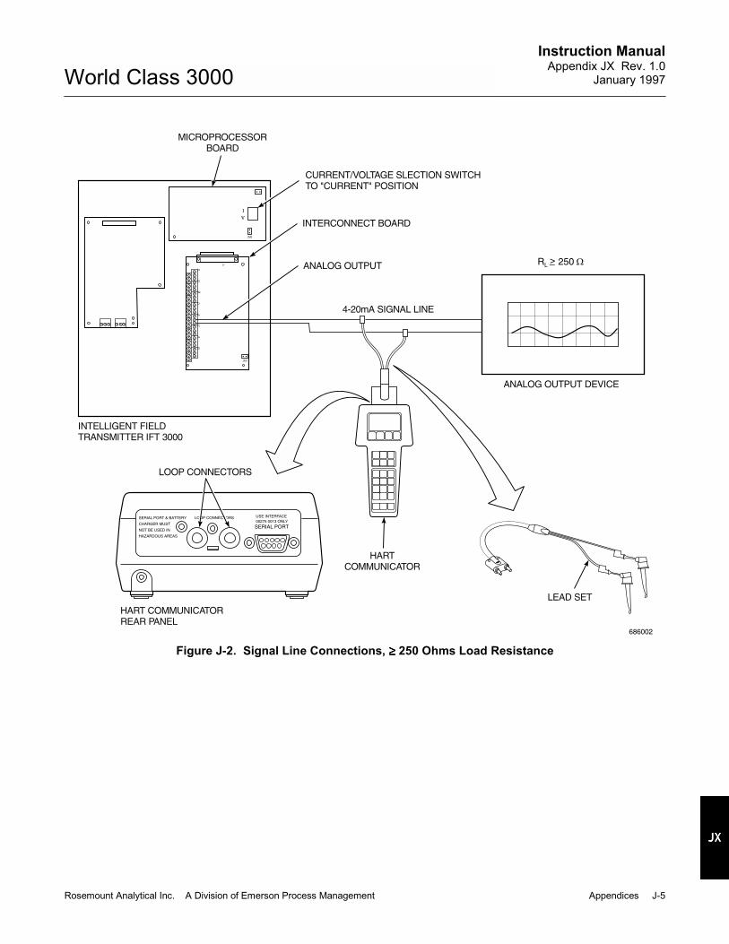
Instruction ManualAppendix JX Rev. 1.0
January 1997
Rosemount Analytical Inc. A Division of Emerson Process Management Appendices J-5
World Class 3000
R 250L>_
LOOP CONNECTORS USE INTERFACE
00275 0013 ONLYSERIAL PORT & BATTERY
CHARGER MUST
NOT BE USED IN
HAZARDOUS AREAS
SERIAL PORT
J1
JM1
JM6
J2
J3
J4
J5
J6
J7
J8
J9
I
V
686002
ANALOG OUTPUT DEVICE
LEAD SET
HARTCOMMUNICATOR
HART COMMUNICATORREAR PANEL
LOOP CONNECTORS
INTELLIGENT FIELDTRANSMITTER IFT 3000
4-20mA SIGNAL LINE
ANALOG OUTPUT
INTERCONNECT BOARD
CURRENT/VOLTAGE SLECTION SWITCHTO "CURRENT" POSITION
MICROPROCESSORBOARD
Figure J-2. Signal Line Connections, ≥≥≥≥ 250 Ohms Load Resistance

Instruction ManualAppendix JX Rev. 1.0January 1997
J-6 Appendices Rosemount Analytical Inc. A Division of Emerson Process Management
World Class 3000
RL < 250 Ω
INTELLIGENT FIELD TRANSMITTER IFT 3000
LOOP CONNECTORS USE INTERFACE00275 0013 ONLY
SERIAL PORT & BATTERY
CHARGER MUST
NOT BE USED IN
HAZARDOUS AREAS
SERIAL PORT
NOTE: THE SIGNAL LOOP MUST BE BROKENTO INSERT THE OPTIONAL 250 OHMLOAD RESISTOR
MICROPROCESSORBOARD
CURRENT/VOLTAGE SELECTION SWITCHTO "CURRENT" POSITION
INTERCONNECT BOARD
ANALOG OUTPUT
4-20mA SIGNAL LINE
ANALOG OUTPUT DEVICE
250 OHMLOADRESISTOR(NOTE)
HARTCOMMUNICATOR
HART COMMUNICATORREAR PANEL
LOOP CONNECTORS
686003
Figure J-3. Signal Line Connections, <250 Ohms Load Resistance
J-5 HART COMMUNICATOR PCCONNECTIONS
There is an option to interface the HART Com-municator with a personal computer. Load thedesignated Cornerstone® software into the PC.Then, link the HART Communicator to the PC
using the interface PC adaptor which connectsto the serial port (on the communicator rearpanel).
Refer to the proper HART Communicatordocumentation in regard to the PC interfaceoption.

Instruction ManualAppendix JX Rev. 1.0
January 1997
Rosemount Analytical Inc. A Division of Emerson Process Management Appendices J-7
World Class 3000
OPERATION
See Safety Data Sheet 1M03296 forsafety related information.
J-6 OFF-LINE AND ON-LINE OPERATIONS
The HART Communicator can be operated bothoff-line and on-line. Off-line operations are thosein which the communicator is not connected tothe IFT system. Off-line operations can includeinterfacing the HART Communicator with a PC(refer to applicable HART Documentation re-garding HART/PC applications).
In the on-line mode, the communicator is con-nected to the 4-20 mA analog output signal line.The communicator is connected in parallel to
the IFT, or in parallel to the 250 ohm load re-sistor.
The opening menu (displayed on the LCD) isdifferent for on-line and off-line operations.When powering up a disconnected (off-line)communicator, the LCD will display the MainMenu. When powering up a connected (on-line)communicator, the LCD will display the On-lineMenu. Refer to the HART Communicator man-ual for detailed menu information.
J-7 MENU TREE FOR HART COMMUNICATOR/WORLD CLASS 3000 IFT APPLICATIONS
This section consists of a menu tree for theHART Communicator. This menu is specific toIFT 3000 applications.

Instruction ManualAppendix JX Rev. 1.0January 1997
J-8 Appendices Rosemount Analytical Inc. A Division of Emerson Process Management
World Class 3000
OxygenEfficiencyStackO2 cellCJtemp
VIEW FLDDEV VARS
PV isPVPV % mgePV AO
PROCESSVARIABLES
DIAG/SERVICE
VIEW PV-Aout
VIEW OUTPUTVARS
VIEW SVSV isSVSV % mge
O2 cellCell TCStack TCCJmV
VIEW FLDDEV mV
Not ApplicableVIEW STATUS
SELF TEST Not Applicable
LOOP TEST Loop testmethod...
Cal Mode
Optrak TG?
PERFORM O2CAL
CalState
PERFORM O2CAL
O2 CALIBRATE
CalStateTimeRemainPresent TGPresent O2
O2 CALSTATUS
Cal slopeCal constCellRes
LASTCALCONSTANTS
ResetCalConstantsmethod...
RESETCALCONSTANTS
D/A trim methodD/A TRIM
O2 Cal method...
DEVICE SETUPPVPV AOPV LRVPV URV
(CONTINUED ONSHEET 2)
686006
Figure J-4. Menu Tree for IFT 3000 Application (Sheet 1 of 3)

Instruction ManualAppendix JX Rev. 1.0
January 1997
Rosemount Analytical Inc. A Division of Emerson Process Management Appendices J-9
World Class 3000
DEVICE SETUPPVPV AOPV LRVPV URV
(CONTINUED ONSHEET 3)
Tag
ASSIGNPV & SV
SELECT O2RANGE
Set O2 Xfer fn
DEVICEINFORMATION
PV isSV is
O2RngeModeHiRnginCal?RngeSwtSPNormal URVNormal LRVHi.mg.URVHi.mg.LRV
ManufacturerDistributorModelDev idTagDescriptorMessageDateFinal asmbly numSnsr s/nFld dev revSoftware revUniversal rev
O2efficiencyStackTempO2 cellTempColdJuncTempO2 cell mVO2 cellTCmVStackTCmVCold Junc mV
PV URVPV LRVXfer fnctnPV % mge
ANALOGOUTPUT
HART OUTPUT
RELAYOUTPUTS
O2
EFFICIENCY
HighTGLowTGCal ModeOPtrak TG?Cal IntrvlNxtCalTimeTGtimePurgeTimeResAirSP
HiAlarmSPLoAlarmSPDeadband
SENSORS
SIGNALCONDITION
OUTPUTCONDITION
CALCULATIONS
O2CALIBRATION
O2 ALARMS
(CONTINUED FROMSHEET 1)
BASIC SETUP
DETAILEDSETUP
PV AOAO Alrm typ
LOOP TEST
D/A TRIM
Poll addrNum req preams
K1
K2
SlopeConstantHeaterSP
Eff.enabled?K1 efficncyK2 efficncyK3 efficncy
Loop testmethod...
D/A trim method...
K1 stateK1 input1K1 input2K1 input3
K2 stateK2 input1K2 input2K2 input3
686007
Figure J-4. Menu Tree for IFT 3000 Application (Sheet 2 of 3)

Instruction ManualAppendix JX Rev. 1.0January 1997
J-10 Appendices Rosemount Analytical Inc. A Division of Emerson Process Management
World Class 3000
DEVICE SETUPPVPV AOPV LRVPV URV
(CONTINUED FROMSHEET 2)
ManufacturerDistributorModelDev idTagDescriptorMessageDateFinal asmbly numSnsr s/nFld dev revHardware revSoftware revUniversal rev
Cal modeOptrak TG?Cal IntrvlTgtimePurgeTimeResAirSPLowTGHighTGCal slopeCal constCellRes
HeaterSPSlopeConstantEff.enabled?K1 efficncyK2 efficncyK3 efficncy
Normal URVNormal LRVHi.mg.URVHi.mg.LRVO2RngeModeHiRnginCal?RngeSwtSPHiAlarmSPLoAlarmSPDeadbandK1 input1K1 input2K1 input3K2 input1K2 input2K2 input3Poll addrNum req preams
DEVICEINFORMATION
CAL INFO
DEVICE CONFIG
OUTPUTSCONFIG
REVIEW
686008
Figure J-4. Menu Tree for IFT 3000 Application (Sheet 3 of 3)

Instruction ManualAppendix JX Rev. 1.0
January 1997
Rosemount Analytical Inc. A Division of Emerson Process Management Appendices J-11
World Class 3000
TROUBLESHOOTING
Consult Safety Data Sheet 1M03296before performing any work on theCENELEC approved IFT 3000.
Install all protective equipment coversand safety ground leads after trouble-shooting. Failure to install covers andground leads could result in seriousinjury or death.
J-8 OVERVIEW
If the HART Communicator fails to functionproperly, verify that the unit's battery pack andmemory module are correctly assembled to thecommunicator. Check the communicator'smodel number. For IFT applications, HARTCommunicator model number 275D9E must beused. If the HART Communicator model numberis correct, and if it is properly assembled, thetroubleshooting flowchart, Figure J-5, may beuseful to find and correct problems.
J-9 TROUBLESHOOTING FLOWCHART
Refer to Figure J-5.

Instruction ManualAppendix JX Rev. 1.0January 1997
J-12 Appendices Rosemount Analytical Inc. A Division of Emerson Process Management
World Class 3000
DOESHART UNIT
HAVEPOWER
?
DOESHART UNITINDICATEBATTERYPOWERGOOD
?
ISHART UNIT
BEING USED"ON-LINE"
?
ISHART UNIT
CONFIGUREDFOR IFT?
IS IFTPOWERED
?
IS IFTEXPERIENCING
FAULTS?
DOESIFT HAVE
MICROPROCESSORBOARDREV.#
3039513G?
CLEAR IFT OF ALL FAULTCONDITIONS.
YES
YES
YES
YES
YES
YES
YES
(GO TOSHEET 2 OF 2)
REPLACE BATTERIES. IFAPPLICABLE, RECHARGENiCad BATTERIES.
VERIFY HART ISCONFIGURED FOR IFT.REFERENCE OFF-LINECONFIGURATION (HARTPOCKET-SIZED MANUAL).
RECONFIGURE HART UNITFOR IFT.
CONTACT SERVICEREPRESENTATIVE.
SUPPLY POWER TO IFT.
NO
NONO
NO
NO
NO
NO
34990012
Figure J-5. Model Number 275D9E, Troubleshooting Flowchart (Sheet 1 of 2)

Instruction ManualAppendix JX Rev. 1.0
January 1997
Rosemount Analytical Inc. A Division of Emerson Process Management Appendices J-13
World Class 3000
ISHART UNIT
INSTALLED IN40-20 mASIGNALLOOP
?
ISANALOGOUTPUT
SELECTED TO4-20 mA
CURRENTSIGNAL
?
ISLOAD
RESISTANCE250 OHMS
?≥
IS250 OHM
LOADRESISTOR
CORRECTLYINSTALLED (SEEINSTALLATION)
?
ISHART UNIT
CONFIGUREDFOR IFT
?
ISHART UNITINSTALLEDPARALLEL
TO IFT?
RECONFIGURE HARTUNIT FOR IFT.
YES
YES
YES
YES
YES
YES
PROGRAM IFT FOR4-20 mA OUTPUT SIGNAL.SELECT CURRENT MODEUSING CURRENT/VOLTAGESELECTION SWITCH ONIFT MICROPROCESSORBOARD.
CONNECT THE HART UNITTO THE 4-20 mA SIGNALLOOP. REFER TO INSTALLATION.IF LOAD RESISTANCE IS<250 OHMS. THE 250 OHMLOAD RESISTOR MUST BEUSED.
INSTALL 250 OHM LOADRESISTOR. (SEEINSTALLATION).
CONTACT SERVICEREPRESENTATIVE.
USE LEAD SET TOCONNECT HART UNIT INPARALLEL TO IFT. HARTUNIT MUST BECONNECTED TO 4-20 mASIGNAL LINE. (SEEINSTALLATION).
VERIFY PROPER IFTCONFIGURATION.CONSULT MENU TREE(FIGURE J-4 OF THISAPPENDIX). REFER TODEVICE CONFIGURATIONSUB-MENU.
NO
NO NO
NO
NO
(CONTINUED FROMSHEET 1 OF 2)
NO
35870007
Figure J-5. Model Number 275D9E, Troubleshooting Flowchart (Sheet 2 of 2)

Instruction ManualAppendix JX Rev. 1.0January 1997
J-14 Appendices Rosemount Analytical Inc. A Division of Emerson Process Management
World Class 3000

Instruction Manual106-300NFX Rev. 4.2
January 2002
Rosemount Analytical Inc. A Division of Emerson Process Management Index 8-1
World Class 3000
SECTION 8INDEX
This index is an alphabetized listing of parts, terms, and procedures having to do with the WorldClass 3000 Oxygen Analyzer with IFT 3000 Intelligent Field Transmitter. Every item listed in thisindex refers to a location in the manual by one or more page numbers.
AAbrasive Shield, 2-3Absolute Temperature, 1-2Air Pressure Regulator Valve, 2-8Analog Output, 2-14, 3-9Arithmetic Constant, 1-2Automatic Calibration, 3-15
CCable Shields, 5-1CAL Key, 3-2CALIBRATE O2 Sub-Menu, 3-6, 3-7Calibration Fitting, 3-10Cell Constant, 1-2Ceramic Diffusor, 2-4Check Valve, 1-4, 3-11Compressed Air, 2-8
DData Key, 3-2Data Menu, 3-3Diffusion Element Dust Seal Packings, 2-7Dip Shunt, 2-13
EElectrical Noise, 5-1Electrostatic Discharge, 5-1Enter key, 3-2
FField Replaceable Cell, 1-3
GGas Stratification, 2-1Grounding, 5-1GUI, 3-1, 5-2
HHeater Power Supply, 1-1, 2-16, 2-19Help Key, 3-2
IInstallation, 2-1Instrument Air, 2-8Intelligent Field Transmitter, 2-9
LLDP, 4-1
MManual Calibration, 3-10Mounting Plate, 1-1, 2-6Multiple Test Gas Sequencer, 2-20Multiple Test Gas Squencer, 1-1Multiprobe Test Gas Sequencer, 2-23
NNernst Equation, 1-2
OOperator Initiated Calibration, 3-13Operator Interface, 1-3
PPROBE DATA Sub-Menu, 3-3Probe Gas Temperature, 2-1Probe Location Selection, 2-1Probe Mechanical Installation, 2-1
RReference Gas, 1-2Relay Output Connections, 2-14

Instruction Manual106-300NFX Rev. 4.2January 2002
8-2 Index Rosemount Analytical Inc. A Division of Emerson Process Management
World Class 3000
SSel key, 4-1Semiautomatic Calibration, 3-10Sensing Point, 2-1Setup Key, 3-2SETUP Sub-Menu, 3-6, 3-8Status Line, 3-3System Cables, 1-1
VVee Deflector Orientation, 2-7
YYttria-stabilized, 1-2
ZZirconia Disc, 1-2

Instruction Manual106-300NFX Rev. 4.2
January 2002
Rosemount Analytical Inc. A Division of Emerson Process Management Drawings and Schematics 9-1
World Class 3000
SECTION 9DRAWINGS AND SCHEMATICS

Instruction Manual106-300NFX Rev. 4.2January 2002
9-2 Drawings and Schematics Rosemount Analytical Inc. A Division of Emerson Process Management
World Class 3000
INTRODUCTION:
FLAMEPROOF APPARATUS OR NON FLAMEPROOF APPARATUS:
POWER DOWN PROCEDURE:
ISOLATION OF ELECTRICAL SUPPLY:
RESTORATION OF SUPPLY FOR ELECTRICAL TESTING:
REMOVAL OF JUNCTION BOX COVER:
WIRING OF THE APPARATUS:
INSTRUCTION BULLETINS (USER MANUAL):
CABLE GLANDS:
THIS SAFETY DATA SHEET APPLIES TO INTELLIGENT FIELD TRANSMITTER(IFT3000), TYPE No. 1U05691. THE APPARATUS IS CERTIFIED EExd IIB T6.:ISSeP CERTIFICATE No.THIS APPARATUS HAS BEEN DESIGNED AND MANUFACTURED TO OPERATESAFELY IN CERTAIN TYPES OF POTENTIALLY EXPLOSIVE ATMOSPHERES. IT IS ESSENTIALTHAT THE EQUIPMENT IS NOT TAMPERED WITH OR DAMAGED IN ANY WAY WHICHMIGHT LEAD TO A REDUCTION IN IT'S ABILITY TO OPERATE SAFELY IN SUCH POTENTIALLYEXPLOSIVE ATMOSPHERES. FOR YOUR OWN SAFETY AND THE SAFETY OF OTHERSPLEASE BRING ANY DAMAGE TO THE ATTENTION OF THE RESPONSIBLE AUTHORITY.
THIS APPARATUS HAS BEEN DESIGNED AND MANUFACTURED IN ACCORDANCEWITH EUROPEAN STANDARDS EN50014 & EN50018. INSTALLATION MAINTENANCEAND REPAIR MUST BE IN ACCORDANCE WITH THE OFFICIAL “CODES OFPRACTICE ON THE INSTALLATION AND MAINTENANCE OF ELECTRICAL APPARATUSIN POTENTIALLY EXPLOSIVE ATMOSPHERES” FOR THE COUNTRY OF INSTALLATION(EXAMPLE: BS5345 IN GREAT BRITAIN). ONLY APPROPRIATELY TRAINED PERSONNELARE AUTHORIZED TO PERFORM ANY WORK ON THIS EQUIPMENT. SUCH PERSONNEL INADDITION TO OPERATING TO THE ABOVE MENTIONED SAFETY STANDARDS, SHOULD TAKENOTE OF THE FOLLOWING SAFETY ISSUES.
(1)THE ROSEMOUNT ENCODE SHEETS (PRODUCT ORDERING MATRIX) ALLOWS A CUSTOMERTO ORDER EITHER THE HAZARDOUS AREA (FLAMEPROOF) VERSION OF THE IFT3000OR THE NON HAZARDOUS AREA VERSION. THE HAZARDOUS AREA VERSION HAS THESYMBOL “EExd” ON THE APPARATUS NAMEPLATE. THE NON HAZARDOUS AREA VERSIONDOES NOT. ENSURE THAT IF YOU HAVE RECEIVED THE NON HAZARDOUS AREA VERSIONTHAT YOU DO NOT INSTALL IT IN A POTENTIALLY EXPLOSIVE ENVIRONMENT.
(2)
THIS PIECE OF APPARATUS IS NOT ITSELF FITTEDWITH A MEANS OF ELECTRICAL ISOLATION. CONSULT YOUR LOCAL CODES OF PRACTICEON THE INSTALLATION AND MAINTENANCE OF ELECTRICAL APPARATUS IN POTENTIALLYEXPLOSIVE ATMOSPHERES (BS5345 IN BRITAIN) FOR INSTRUCTION ON THE ISOLATION OFELECTRICAL SUPPLY TO THE APPARATUS. FURTHER MORE THERE MUST BE “EFFECTIVEMEASURES TO PREVENT THE RESTORATION OF SUPPLY TO THE APPARATUS WHILE THERISK OF EXPOSING UNPROTECTED LIVE CONDUCTORS TO AN EXPLOSIVE ATMOSPHERECONTINUES”:BS5345 PART 1 1989 SECTION 18.
“WHERE, FOR PURPOSES OFELECTRICAL TESTING, IT IS ESSENTIAL TO RESTORE THE SUPPLY BEFORE THE APPARATUSIS REASSEMBLED, THEN THIS WORK SHOULD BE UNDER A CONTROLLED PROCEDUREAND THE SPECIFIC LOCATION ASSESSED TO ENSURE THAT POTENTIALLY FLAMMABLEGAS OR VAPOUR IS ABSENT”:BS5345 PART 1 1989 SECTION 23.
DO NOT OPEN THE APPARATUS COVERWHILE THE APPARATUS IS ENERGIZED. WAIT 10 MINUTES AFTER DEENERGIZING BEFOREOPENING THE APPARATUS.
(3) EACH APPARATUS MUST BE WIRED AS DETAILED INTHE APPLICABLE INSTRUCTION BULLETIN (USER MANUAL).
(4) THE APPLICABLE INSTRUCTION BULLETIN IS:IB-106-300NFX: USED WITH IFT3000 ELECTRONICS.THIS INSTRUCTION BULLETIN CONTAINS ESSENTIAL INFORMATION & MUST BE USEDWHEN WORKING ON THE APPARATUS.
(5) HAWKE CABLE GLAND, TYPE ICG653 (BASEEFA CERTIFICATE:BAS No. EX 85B1258U) OR AN EQUIVALENT MUST BE USED. THIS GLAND IS ABARRIER (STOPPER) GLAND. A FEATURE OF THIS GLAND IS THAT A COMPOUNDFILLED PACKING MATERIAL (PUTTY), FORMS A BARRIER BETWEEN THE INDIVIDUALINSULATED CONDUCTORS OF THE CABLE. THIS BARRIER ACTS TO PREVENT ENTRYINTO THE CABLE OF THE PRODUCTS OF AN EXPLOSION WITHIN THE ENCLOSURE.THIS GLAND IS CERTIFIED Exd IIC.
TH
ISD
RA
WIN
GA
FF
EC
TS
CE
NE
LE
CC
ER
TIF
ICA
TIO
N.
NO
RE
VIS
ION
AL
LO
WE
DW
ITH
OU
TC
HE
CK
ING
AN
DA
PP
RO
VA
LB
YT
HE
PR
OD
UC
TE
NG
INE
ER
.
DEO
DEO
DEO
05867
14/12/93
05932
06435
7-4-94
17-5-95
1
2
3
TIT
LE
SIZ
E
SC
AL
E
DW
GN
O
SH
EE
T
SA
FE
TY
DA
TA
SH
EE
TF
OR
CE
NE
LE
CA
PP
RO
VE
DIF
T3
00
0
1O
F2
1M
03
29
6 Me
asu
rem
en
tC
on
trol
An
aly
tica
l 34
99
00
01

Instruction Manual106-300NFX Rev. 4.2
January 2002
Rosemount Analytical Inc. A Division of Emerson Process Management Drawings and Schematics 9-3
World Class 3000
TH
ISD
RA
WIN
GA
FF
EC
TS
CE
NE
LE
CC
ER
TIF
ICA
TIO
N.
NO
RE
VIS
ION
AL
LO
WE
DW
ITH
OU
TC
HE
CK
ING
AN
DA
PP
RO
VA
LB
YT
HE
PR
OD
UC
TE
NG
INE
ER
.
DEO
DEO
DEO
05867
13/12/93
05932
06435
7-4-94
17-5-95
1
2
3
TIT
LE
SIZ
E
SC
AL
E
DW
GN
O
SH
EE
T
SA
FE
TY
DA
TA
SH
EE
TF
OR
CE
NE
LE
CA
PP
RO
VE
DIF
T3
00
0
2
1M
03
29
6
(6)ON EARLIER INSTALLATIONS WESTINGHOUSE/ROSEMOUNT SUPPLIED A CABLEBETWEEN THE DIGITAL ELECTRONICS AND PROBE (MODEL 218).THE GLANDS ON THIS CABLE - ALTHOUGH HAWKE GLANDS CERTIFIED Exd IICWERE NOT OF THE HAWKE BARRIER (STOPPER) GLAND, TYPE ICG653 VARIETY.THESE GLANDS MUST NOT BE USED. ROSEMOUNT CAN SUPPLY A BARRIER GLANDKIT TO REPLACE SUCH GLANDS. THE KIT (PART No. 1U03066G07), COMPRISESOF TWO BARRIER GLANDS COMPLETE WITH PUTTY, CRIMPS AND AN INSTRUCTIONSHEET. PLEASE NOTE THAT YOU SHOULD USE ONLY PUTTY WHICH IS PLASTIC& CAPABLE OF BEING MIXED. YOU SHOULD NOT USE CRYSTALISED OR HARDPUTTY.
(7)THIS APPARATUS DOES NOT INCLUDE ANY SPECIFIC MEANS FOR CABLE ANCHORAGE.THE CABLE GLANDS CHOSEN FOR THE MAINS, PROBE, AND SIGNAL CABLES MUSTBE OF A TYPE WHICH SUPPLY CABLE ANCHORAGE. THE BARRIER (STOPPER) GLANDSUPPLIED BY ROSEMOUNT AS PART OF THE PROBE CABLE ASSEMBLY, WILL GIVESUCH CABLE ANCHORAGE.
(8) ALL CABLE ENTRY PORTS WHICH ARE UNUSEDARE TO BE CLOSED OFF WITH THREADED PLUGS CERTIFIED Exd IIC. THERE SHOULDBE A MINIMUM OF 5 THREADS ENGAGED AND THE THREADS SEALED WITHTHREADLOCK (LOCKTITE 271 OR EQUIVALENT).
(9) ENSURE THAT NAMEPLATE IS AT ALL TIMES VISIBLE.AT INSTALLATION, ALLOWANCE MUST BE MADE FOR THIS.
(10) THE APPARATUS HAS BEEN FITTED WITH BOTHEXTERNAL AND INTERNAL EARTHING POINTS. ADEQUATE EARTH CONNECTIONSSHOULD BE MADE TO BOTH THESE POINTS.
(11)THIS APPARATUS CONTAINS A NUMBER OF SHEET METALWORK PANELS FOR MOUNTINGTHE PRINTER CIRCUIT BOARDS. BECAUSE THESE PANELS ARE IN CLOSE PROXIMITYTO THE WALLS OF THE FLAMEPROOF ENCLOSURE, IT WAS NECESSARY TOPERFORATE THEM WITH HOLES AND SLOTS. THESE HOLES AND SLOTS PREVENTPRESSURE PILING BETWEEN THE PANELS AND THE WALLS & LID OF THEENCLOSURE. DO NOT DO ANYTHING WHICH MIGHT OBSCURE THESE SLOTS & HOLES.
(12)THE IFT3000 IS A HEAVY PIECE OF APPARATUS. LIFTING AND CARRYING PROCEDURESSHOULD TAKE ACCOUNT OF THIS WEIGHT.
(13)HART IS A COMMUNICATIONS PROTOCOL WHICH ALLOWS REMOTE COMMUNICATIONWITH THE IFT3000 VIA THE 4-20mA OUTPUT. BECAUSE, ON THE IFT3000, THEHART OPTION IS NOT PROTECTED BY ENERGY LIMITING BARRIERS, IT MUST NOTBE INTERFACED FROM WITHIN THE HAZARDOUS AREA. THE 4-20mA CABLES SHOULDBE ROUTED OUTSIDE THE HAZARDOUS AREA, AND THE CONNECTION MADE OUTTHERE. NOTE THIS IS THE CASE EVEN WHEN USING THE INTRINSICALLY SAFEVERSION OF THE THE HANDHELD COMMUNICATOR. THE LIMITATION (ie, NO ENERGYLIMITING BARRIER) LIES IN THE IFT3000 NOT IN THE HANDHELD UNIT.
EXISTING WESTINGHOUSE/ROSEMOUNT SUPPLIED CABLE:
CABLE ANCHORAGE:
UNUSED CABLE ENTRY PORTS:
NAMEPLATE (LABEL):
EARTHING OF THE APPARATUS:
SHEET METALWORK PANELS:
LIFTING AND CARRYING:
CONNECTION TO HART OPTION:
Me
asu
rem
en
tC
on
trol
An
aly
tica
l 34
99
00
02

Instruction Manual106-300NFX Rev. 4.2January 2002
9-4 Drawings and Schematics Rosemount Analytical Inc. A Division of Emerson Process Management
World Class 3000
INTRODUCTION:
FLAMEPROOF APPARATUS OR NON FLAMEPROOF APPARATUS:
POWER DOWN PROCEDURE:
ISOLATION OF ELECTRICAL SUPPLY:
RESTORATION OF SUPPLY FOR ELECTRICAL TESTING:
REMOVAL OF JUNCTION BOX COVER:
WIRING OF THF APPARATUS:
INSTRUCTION BULLETINS (USER MANUAL):
CABLE GLANDS:
THIS SAFETY DATA SHEET APPLIES TO BOTH, HEATER POWER SUPPLY3000 (HPS3000), TYPE No. 1U05667 AND TO DIGITAL ELECTRONICS, TYPE No. 1U03083.
THESE APPARATUS ARE CERTIFIED EExd IIC T6.
ISSeP CERTIFICATE No. 92C.103.1037, AND INIEX CERTIFICATE No. 87.103.578.THESE APPARATUS HAVE BEEN DESIGNED AND MANUFACTURED TO OPERATESAFELY IN CERTAIN TYPES OF POTENTIALLY EXPLOSIVE ATMOSPHERES. IT IS ESSENTIALTHAT THE EQUIPMENT IS NOT TAMPERED WITH OR DAMAGED IN ANY WAY WHICHMIGHT LEAD TO A REDUCTION IN IT'S ABILITY TO OPERATE SAFELY IN SUCH POTENTIALLYEXPLOSIVE ATMOSPHERES. FOR YOUR OWN SAFETY AND THE SAFETY OF OTHERSPLEASE BRING ANY DAMAGE TO THE ATTENTION OF THE RESPONSIBLE AUTHORITY.
THESE APPARATUS HAVE BEEN DESIGNED AND MANUFACTURED IN ACCORDANCEWITH EUROPEAN STANDARDS EN50014 & EN50018. INSTALLATION MAINTENANCEAND REPAIR MUST BE IN ACCORDANCE WITH THE OFFICIAL “CODES OFPRACTICE ON THE INSTALLATION AND MAINTENANCE OF ELECTRICAL APPARATUSIN POTENTIALLY EXPLOSIVE ATMOSPHERES” FOR THE COUNTRY OF INSTALLATION(EXAMPLE: BS5345 IN GREAT BRITAIN). ONLY APPROPRIATELY TRAINED PERSONNELARE AUTHORIZED TO PERFORM ANY WORK ON THIS EQUIPMENT. SUCH PERSONNEL INADDITION TO OPERATING TO THE ABOVE MENTIONED SAFETY STANDARDS, SHOULD TAKENOTE OF THE FOLLOWING SAFETY ISSUES.
(1)
THE ROSEMOUNT ENCODE SHEETS (PRODUCT ORDERING MATRIX) ALLOWS A CUSTOMERTO ORDER EITHER THE HAZARDOUS AREA (FLAMEPROOF) VERSION OF THE APPARATUSOR THE NON HAZARDOUS AREA VERSION. THE HAZARDOUS AREA VERSION HAS THESYMBOL “EExd” ON THE APPARATUS NAMEPLATE. THE NON HAZARDOUS AREA VERSIONDOES NOT. ENSURE THAT IF YOU HAVE RECEIVED THE NON HAZARDOUS AREA VERSIONTHAT YOU DO NOT INSTALL IT IN A POTENTIALLY EXPLOSIVE ENVIRONMENT.
(2)
THIS PIECE OF APPARATUS IS NOT ITSELF FITTEDWITH A MEANS OF ELECTRICAL ISOLATION. CONSULT YOUR LOCAL CODES OF PRACTICEON THE INSTALLATION AND MAINTENANCE OF ELECTRICAL APPARATUS IN POTENTIALLYEXPLOSIVE ATMOSPHERES (BS5345 IN BRITAIN) FOR INSTRUCTION ON THE ISOLATION OFELECTRICAL SUPPLY TO THE APPARATUS. FURTHER MORE THERE MUST BE “EFFECTIVEMEASURES TO PREVENT THE RESTORATION OF SUPPLY TO THE APPARATUS WHILE THERISK OF EXPOSING UNPROTECTED LIVE CONDUCTORS TO AN EXPLOSIVE ATMOSPHERECONTINUES”:BS5345 PART 1 1989 SECTION 18.
“WHERE, FOR PURPOSES OFELECTRICAL TESTING, IT IS ESSENTIAL TO RESTORE THE SUPPLY BEFORE THE APPARATUSIS REASSEMBLED, THEN THIS WORK SHOULD BE UNDER A CONTROLLED PROCEDUREAND THE SPECIFIC LOCATION ASSESSED TO ENSURE THAT POTENTIALLY FLAMMABLEGAS OR VAPOUR IS ABSENT”:BS5345 PART 1 1989 SECTION 23.
DO NOT REMOVE THE JUNCTION BOX COVERWHILE THE APPARATUS IS ENERGIZED. WAIT 10 MINUTES AFTER DEENERGIZING BEFOREOPENING THE APPARATUS.
(3) EACH APPARATUS MUST BE WIRED AS DETAILED INTHE APPLICABLE INSTRUCTION BULLETIN (USER MANUAL).
(4) THE APPLICABLE INSTRUCTION BULLETINS ARE:IB-106-300NEX:“EXCHANGE PROBE” CONFIGURATION & “FULLY CENELEC” CONFIGURATION.IB-106-300NFX: USED WITH IFT3000 ELECTRONICS.IB-106-300NCX: USED WITH CRE3000 ELECTRONICS.THESE INSTRUCTION BULLETINS CONTAIN ESSENTIAL INFORMATION & MUST BE USEDWHEN WORKING ON THE APPARATUS.
(5) HAWKE CABLE GLAND, TYPE ICG653 (BASEEFA CERTIFICATE:BAS No. EX 85B1258U) OR AN EQUIVALENT MUST BE USED. THIS GLAND IS ABARRIER (STOPPER) GLAND. A FEATURE OF THIS GLAND IS THAT A COMPOUNDFILLED PACKING MATERIAL (PUTTY), FORMS A BARRIER BETWEEN THE INDIVIDUALINSULATED CONDUCTORS OF THE CABLE. THIS BARRIER ACTS TO PREVENT ENTRYINTO THE CABLE OF THE PRODUCTS OF AN EXPLOSION WITHIN THE ENCLOSURE.THIS GLAND IS CERTIFIED EExd IIC.
TH
ISD
RA
WIN
GA
FF
EC
TS
CE
NE
LE
CC
ER
TIF
ICA
TIO
N.
NO
RE
VIS
ION
AL
LO
WE
DW
ITH
OU
TC
HE
CK
ING
AN
DA
PP
RO
VA
LB
YT
HE
PR
OD
UC
TE
NG
INE
ER
.
DEO
DEO
DEO
05554
17-2-93
05856
05933
13-12-93
7-4-94
1
2
3
TIT
LE
SIZ
E
SC
AL
E
DW
GN
O
SH
EE
T
SA
FE
TY
DA
TA
SH
EE
TF
OR
CE
NE
LE
CA
PP
RO
VE
DH
PS
30
00
&C
EN
EL
EC
AP
PR
OV
ED
DIG
.E
LE
CT
RO
NIC
S
1O
F2
1M
03
24
3
Me
asu
rem
en
tC
on
trol
An
aly
tica
l
34
99
00
03
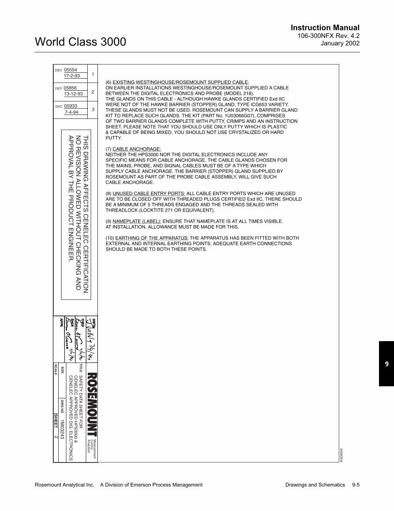
Instruction Manual106-300NFX Rev. 4.2
January 2002
Rosemount Analytical Inc. A Division of Emerson Process Management Drawings and Schematics 9-5
World Class 3000
TH
ISD
RA
WIN
GA
FF
EC
TS
CE
NE
LE
CC
ER
TIF
ICA
TIO
N.
NO
RE
VIS
ION
AL
LO
WE
DW
ITH
OU
TC
HE
CK
ING
AN
DA
PP
RO
VA
LB
YT
HE
PR
OD
UC
TE
NG
INE
ER
.
DEO
DEO
DEO
05554
17-2-93
05856
05933
13-12-93
7-4-94
1
2
3
TIT
LE
SIZ
E
SC
AL
E
DW
GN
O
SH
EE
T
SA
FE
TY
DA
TA
SH
EE
TF
OR
CE
NE
LE
CA
PP
RO
VE
DH
PS
30
00
&C
EN
EL
EC
AP
PR
OV
ED
DIG
.E
LE
CT
RO
NIC
S
2
1M
03
24
3
Me
asu
rem
en
tC
on
trol
An
aly
tica
l
(6)ON EARLIER INSTALLATIONS WESTINGHOUSE/ROSEMOUNT SUPPLIED A CABLEBETWEEN THE DIGITAL ELECTRONICS AND PROBE (MODEL 218).THE GLANDS ON THIS CABLE - ALTHOUGH HAWKE GLANDS CERTIFIED Exd IICWERE NOT OF THE HAWKE BARRIER (STOPPER) GLAND, TYPE ICG653 VARIETY.THESE GLANDS MUST NOT BE USED. ROSEMOUNT CAN SUPPLY A BARRIER GLANDKIT TO REPLACE SUCH GLANDS. THE KIT (PART No. 1U03066G07), COMPRISESOF TWO BARRIER GLANDS COMPLETE WITH PUTTY, CRIMPS AND AN INSTRUCTIONSHEET. PLEASE NOTE THAT YOU SHOULD USE ONLY PUTTY WHICH IS PLASTIC& CAPABLE OF BEING MIXED. YOU SHOULD NOT USE CRYSTALIZED OR HARDPUTTY.
(7)NEITHER THE HPS3000 NOR THE DIGITAL ELECTRONICS INCLUDE ANYSPECIFIC MEANS FOR CABLE ANCHORAGE. THE CABLE GLANDS CHOSEN FORTHE MAINS, PROBE, AND SIGNAL CABLES MUST BE OF A TYPE WHICHSUPPLY CABLE ANCHORAGE. THE BARRIER (STOPPER) GLAND SUPPLIED BYROSEMOUNT AS PART OF THE PROBE CABLE ASSEMBLY, WILL GIVE SUCHCABLE ANCHORAGE.
(8) ALL CABLE ENTRY PORTS WHICH ARE UNUSEDARE TO BE CLOSED OFF WITH THREADED PLUGS CERTlFIED Exd IIC. THERE SHOULDBE A MINIMUM OF 5 THREADS ENGAGED AND THE THREADS SEALED WITHTHREADLOCK (LOCKTITE 271 OR EQUIVALENT).
(9) ENSURE THAT NAMEPLATE IS AT ALL TIMES VISIBLE.AT INSTALLATION, ALLOWANCE MUST BE MADE FOR THIS.
(10) THE APPARATUS HAS BEEN FITTED WITH BOTHEXTERNAL AND INTERNAL EARTHING POINTS. ADEQUATE EARTH CONNECTIONSSHOULD BE MADE TO BOTH THESE POINTS.
EXISTING WESTINGHOUSE/ROSEMOUNT SUPPLIED CABLE:
CABLE ANCHORAGE:
UNUSED CABLE ENTRY PORTS:
NAMEPLATE (LABEL):
EARTHING OF THE APPARATUS:
34
99
00
04

Instruction Manual106-300NFX Rev. 4.2January 2002
9-6 Drawings and Schematics Rosemount Analytical Inc. A Division of Emerson Process Management
World Class 3000
TH
ISD
RA
WIN
GA
FF
EC
TS
CE
NE
LE
CC
ER
TIF
ICA
TIO
N.
NO
RE
VIS
ION
AL
LO
WE
DW
ITH
OU
TC
HE
CK
ING
AN
DA
PP
RO
VA
LB
YT
HE
PR
OD
UC
TE
NG
INE
ER
.
DEO
DEO
05553
16-2-93
05934
4-2-94
1
2
TIT
LE
SIZ
E
SC
AL
E
DW
GN
O
SH
EE
T
SA
FE
TY
DA
TA
SH
EE
TF
OR
CE
NE
LE
CA
PP
RO
VE
DW
C3
00
0P
RO
BE
1O
F6
1M
03
22
6
Me
asu
rem
en
tC
on
trol
An
aly
tica
l
INTRODUCTION:
POWER DOWN PROCEDURE:
ISOLATION OF ELECTRICAL SUPPLY:
RESTORATION OF SUPPLY FOR ELECTRICAL TESTING:
REMOVAL OF JUNCTION BOX COVER:
THREADED JOINTS:
THIS SAFETY DATA SHEET APPLIES TO WC3000 INSITU OXYGEN ANALYZER(PROBE),TYPE No. 1U05680. THIS OXYGEN ANALYZER IS CERTIFIED EExd lIB 370 (T1):ISSeP CERTIFICATE No. 93C.103.1067.THIS PIECE OF EQUIPMENT HAS BEEN DESIGNED AND MANUFACTURED TO OPERATESAFELY IN CERTAIN TYPES OF POTENTIALLY EXPLOSIVE ATMOSPHERES. IT IS ESSENTIALTHAT THE EQUIPMENT IS NOT TAMPERED WITH OR DAMAGED IN ANY WAY WHICHMIGHT LEAD TO A REDUCTION IN IT'S ABILITY TO OPERATE SAFELY IN SUCH POTENTIALLYEXPLOSIVE ATMOSPHERES. FOR YOUR OWN SAFETY AND THE SAFETY OF OTHERSPLEASE BRING ANY DAMAGE TO THE ATTENTION OF THE RESPONSIBLE AUTHORITY.
THIS PIECE OF EQUIPMENT HAS BEEN DESIGNED AND MANUFACTURED INACCORDANCE WITH EUROPEAN STANDARDS EN50014 & EN50018. INSTALLATIONMAINTENANCE AND REPAIR MUST BE IN ACCORDANCE WITH THE OFFICIAL “CODESOF PRACTICE ON THE INSTALLATION AND MAINTENANCE OF ELECTRICAL APPARATUSIN POTENTIALLY EXPLOSIVE ATMOSPHERES’' FOR THE COUNTRY OF INSTALLATION(EXAMPLE: BS5345 IN GREAT BRITAIN). ONLY APPROPRIATELY TRAINED PERSONNELARE AUTHORIZED TO PERFORM ANY WORK ON THIS EQUIPMENT. SUCH PERSONNEL INADDITION TO OPERATING TO THE ABOVE MENTIONED SAFETY STANDARDS, SHOULD TAKENOTE OF THE FOLLOWING SAFETY ISSUES.
NOTE: THROUGHOUT THIS DATA SHEET, CONTINUOUS REFERENCE WILL BE MADE TOFIGURE 1.
(1)
THIS PIECE OF APPARATUS IS NOT ITSELF FITTEDWITH A MEANS OF ELECTRICAL ISOLATION. CONSULT YOUR LOCAL CODES OF PRACTICEON THE INSTALLATION AND MAINTENANCE OF ELECTRICAL APPARATUS IN POTENTIALLYEXPLOSIVE ATMOSPHERES (BS5345 IN BRITAIN) FOR INSTRUCTION ON THE ISOLATION OFELECTRICAL SUPPLY TO THE APPARATUS. FURTHER MORE THERE MUST BE “EFFECTIVEMEASURES TO PREVENT THE RESTORATION OF SUPPLY TO THE APPARATUS WHILE THERISK OF EXPOSING UNPROTECTED LIVE CONDUCTORS TO AN EXPLOSIVE ATMOSPHERECONTINUES”:BS5345 PART 1 1989 SECTION 18.
“WHERE, FOR PURPOSES OFELECTRICAL TESTING, IT IS ESSENTIAL TO RESTORE THE SUPPLY BEFORE THE APPARATUSIS REASSEMBLED, THEN THIS WORK SHOULD BE UNDER A CONTROLLED PROCEDUREAND THE SPECIFIC LOCATION ASSESSED TO ENSURE THAT POTENTIALLY FLAMMABLEGAS OR VAPOUR IS ABSENT”:BS5345 PART 1 1989 SECTION 23.
DO NOT REMOVE THE JUNCTION BOX COVER(ITEM 2) WHILE THE APPARATUS IS ENERGIZED. DO NOT REMOVE THE JUNCTION BOXCOVER WHEN A POTENTIALLY EXPLOSIVE ATMOSPHERE IS PRESENT. REMEMBER (ALTHOUGHTHE UNIT HAS BEEN POWERED DOWN AND THE PROBE HEATER HAS BEEN ALLOWED TOCOOL DOWN), THE TEMPERATURE ON THE INTERIOR OF THE PROBE TUBE (ITEM 1) WILL BESIMILAR TO THE TEMPERATURE OF THE EXHAUST GAS. IF THERE IS A POTENTIALLYEXPLOSIVE ATMOSPHERE IN THE REGION OF THE JUNCTION BOX (ITEM 3), THIS GAS WILL,ON THE REMOVAL OF THE JUNCTION BOX COVER BE EXPOSED TO THE HOT SURFACE OFTHE TUBE INTERIOR (ITEM 1).
(2) THE JOINT BETWEEN THE JUNCTION BOX (ITEM 3) AND THEJUNCTION BOX LID (ITEM 2) IS A THREADED JOINT. SO ALSO IS THE JOINT BETWEENTHE PROBE END FLANGE (ITEM 4) AND THE FLAME ARRESTOR HUB (ITEM 5). BOTHTHESE JOINTS ARE SECURED BY SET SCREWS (ITEMS 6 & 7). BEFORE REMOVINGTHE JUNCTION BOX COVER (ITEM 2) OR THE FLAME ARRESTOR HUB (ITEM 5), FULLYREMOVE THE SET-SCREWS (ITEMS 6 & 7) FROM THEIR TAPPED HOLES. FAILURE TODO THIS COULD RESULT IN DAMAGE TO THE THREADS OF THE JUNCTION BOX (ITEM 3)AND THE PROBE END FLANGE (ITEM 4) BY THE SETSCREWS BEING DRAWN OVERTHE THREADS. REMEMBER WHEN REFITTING THE JUNCTION BOX LID AND THE FLAMEARRESTOR HUB TO LOCK IN PLACE WITH THE SETSCREWS.THE MATERIAL OF THE JUNCTION BOX AND THE JUNCTION BOX LID IS ALUMINUMALLOY. SPECIAL CARE SHOULD BE TAKEN TO AVOID DAMAGE TO THE THREADS.NOTE THAT ROSEMOUNT SUPPLIES ALLEN KEYS FOR REMOVAL & REPLACEMENT OF THESETSCREWS.
34
99
00
05

Instruction Manual106-300NFX Rev. 4.2
January 2002
Rosemount Analytical Inc. A Division of Emerson Process Management Drawings and Schematics 9-7
World Class 3000
TH
ISD
RA
WIN
GA
FF
EC
TS
CE
NE
LE
CC
ER
TIF
ICA
TIO
N.
NO
RE
VIS
ION
AL
LO
WE
DW
ITH
OU
TC
HE
CK
ING
AN
DA
PP
RO
VA
LB
YT
HE
PR
OD
UC
TE
NG
INE
ER
.
DEO
DEO
05553
16-2-93
05934
4-2-94
1
2
TIT
LE
SIZ
E
SC
AL
E
DW
GN
O
SH
EE
T
SA
FE
TY
DA
TA
SH
EE
TF
OR
CE
NE
LE
CA
PP
RO
VE
DW
C3
00
0P
RO
BE
2
1M
03
22
6
Me
asu
rem
en
tC
on
trol
An
aly
tica
l
(3)PROBE TUBE (ITEM 1): TO PROVIDE RESISTANCE AGAINST THE EFFECTS OF CORROSION
AND ABRASION, THE PROBE TUBE HAS BEEN MANUFACTURED FROM 4.75mm WALL,316 SERIES STAINLESS STEEL FOR THE MAJORITY OF APPLICATIONS THE RESISTANCEAFFORDED BY THIS PROBE TUBE AGAINST CORROSION AND ABRASION IS MORETHAN ADEQUATE. FOR APPLICATIONS IN WHICH THE EFFECTS OF CORROSION ORABRASION ARE SIGNIFICANT, ROSEMOUNT CAN SUPPLY AN ABRASIVE SHIELD.
FLAME ARRESTOR HUB (ITEM 5): THE FLAME ARRESTOR HUB HAS BEENMANUFACTURED FROM 316 SERIES STAINLESS STEEL AT ITS THINNEST SECTION(BETWEEN THE O/D OF THE HUB AND THE MAXIMUM MAJOR DIAMETER OF THEM70 X 2 X 6H THREAD: SEE FIGURE 2). THE MINIMUM MATERIAL THICKNESS IS2.75mm. FOR THE MAJORITY OF APPLICATIONS THE PROTECTION AFFORDED BYTHIS ARRANGEMENT AGAINST THE EFFECTS OF CORROSION AND ABRASION ISMORE THAN ADEQUATE. FOR APPLICATIONS IN WHICH THE EFFECTS OF CORROSIONOR ABRASION ARE SIGNIFICANT, ROSEMOUNT CAN SUPPLY AN ABRASIVE SHIELD.
CORROSION AND ABRASION:
34
99
00
06

Instruction Manual106-300NFX Rev. 4.2January 2002
9-8 Drawings and Schematics Rosemount Analytical Inc. A Division of Emerson Process Management
World Class 3000
TH
ISD
RA
WIN
GA
FF
EC
TS
CE
NE
LE
CC
ER
TIF
ICA
TIO
N.
NO
RE
VIS
ION
AL
LO
WE
DW
ITH
OU
TC
HE
CK
ING
AN
DA
PP
RO
VA
LB
YT
HE
PR
OD
UC
TE
NG
INE
ER
.
DEO
DEO
05553
16-2-93
05934
4-2-94
1
2
TIT
LE
SIZ
E
SC
AL
E
DW
GN
O
SH
EE
T
SA
FE
TY
DA
TA
SH
EE
TF
OR
CE
NE
LE
CA
PP
RO
VE
DW
C3
00
0P
RO
BE
3
1M
03
22
6
Me
asu
rem
en
tC
on
trol
An
aly
tica
l
(4) EACH OF THE THREE BULKHEAD UNION FITTINGS (ITEM 8)HAS BEEN FITTED WITH A CAPILLARY ARRAY, (BREATHING DEVICE): SEE FIGURE 3.WHEN FITTING TUBING, (0.25 INCH O/D), TO THE REFERENCE AIR AND CALIBRATIONGAS PORTS, TAKE CARE NOT TO DAMAGE THE BREATHING DEVICES. THE VENT PORTSHOULD BE LEFT CLEAR OF OBSTRUCTIONS.
(5) THE PROBE SHOULD BE WIRED AS SHOWN IN FIGURE 4.
(6) THE FOLLOWING REPAIRS ARE THE ONLY REPAIRS WHICH THECUSTOMER IS ALLOWED TO MAKE:
REPLACEMENT OF ZIRCONIUM CELL (ITEM 9) - CELL REPLACEMENT KIT -.
REPLACEMENT OF STRUT ASSEMBLY (ITEM 10). THE RESISTANCE OF THEREPLACEMENT HEATER MUST BE 11 OHMS OR GREATER
REPLACEMENT OF CONTACT AND THERMOCOUPLE ASSEMBLY (ITEM 11).
REPLACEMENT OF FLAME ARRESTOR HUB ASSEMBLY (ITEM 5).
REPLACEMENT OF VEE DEFLECTOR ASSEMBLY (ITEM 12).
REPLACEMENT OF CERAMIC DIFFUSION ELEMENT (ITEM 13) - DIFFUSION ELEMENTREPLACEMENT KIT - . TAKE CARE NOT TO DAMAGE THE FLAME ARRESTOR (ITEM 18)ITSELF OR THE FLAME ARRESTOR HUB.
BREATHING DEVICES:
WIRING DIAGRAM:
CUSTOMER REPAIRS:
34
99
00
07

Instruction Manual106-300NFX Rev. 4.2
January 2002
Rosemount Analytical Inc. A Division of Emerson Process Management Drawings and Schematics 9-9
World Class 3000
TH
ISD
RA
WIN
GA
FF
EC
TS
CE
NE
LE
CC
ER
TIF
ICA
TIO
N.
NO
RE
VIS
ION
AL
LO
WE
DW
ITH
OU
TC
HE
CK
ING
AN
DA
PP
RO
VA
LB
YT
HE
PR
OD
UC
TE
NG
INE
ER
.
DEO
DEO
05553
16-2-93
05934
4-2-94
1
2
TIT
LE
SIZ
E
SC
AL
E
DW
GN
O
SH
EE
T
SA
FE
TY
DA
TA
SH
EE
TF
OR
CE
NE
LE
CA
PP
RO
VE
DW
C3
00
0P
RO
BE
1M
03
22
6
Me
asu
rem
en
tC
on
trol
An
aly
tica
l
(7) CABLE ENTRY TO THIS APPARATUS IS VIA THE 1/2" NPT CABLEENTRY PORT PROVIDED. THE CABLE ENTRY MUST MAINTAIN THE FLAMEPROOFPROPERTIES OF THE ENCLOSURE. ROSEMOUNT CAN SUPPLY A CABLE WHICHIS TERMINATED WITH A BARRIER (STOPPER) GLAND. A FEATURE OF THIS GLANDIS THAT A COMPOUND FILLED PACKING MATERIAL (PUTTY), FORMS A BARRIERBETWEEN THE INDIVIDUAL INSULATED CONDUCTORS OF THE CABLE. THISBARRIER ACTS TO PREVENT ENTRY INTO THE CABLE OF THE PRODUCTS OFAN EXPLOSION WITHIN THE ENCLOSURE. THE GLAND IS CERTIFIED Exd IIC.
ON EARLIER VERSIONS OF THE ABOVE CABLE SUPPLIED BYWESTINGHOUSE/ROSEMOUNT, THE GLANDS, ALTHOUGH CERTIFIED Exd IIC,WERE NOT OF THE BARRIER GLAND TYPE. THIS GLAND SHOULD NOT BE USEDWITH THE WC3000 INSITU OXYGEN ANALYZER. ROSEMOUNT CAN SUPPLY ABARRIER GLAND KIT TO REPLACE SUCH GLANDS. THE KIT (P/N 1U03066G07),COMPRISES OF TWO BARRIER GLANDS COMPLETE WITH PUTTY, CRIMPS ANDAN INSTRUCTION SHEET. PLEASE NOTE THAT YOU SHOULD USE ONLY PUTTYWHICH IS PLASTIC AND CAPABLE OF BEING MIXED. YOU SHOULD NOT USECRYSTALIZED OR HARD PUTTY.
(8) THE PROBE JUNCTION BOX DOES NOT INCLUDE ANYSPECIFIC MEANS FOR CABLE ANCHORAGE. THE CABLE GLAND CHOSEN MUSTBE ONE WHICH PROVIDES CABLE ANCHORAGE. THE BARRIER (STOPPER) GLANDSUPPLIED BY ROSEMOUNT AS PART OF THE PROBE CABLE ASSEMBLY, WILLPROVIDE CABLE ANCHORAGE.
(9) I DEPENDING ON THE ELECTRONICSCONTROL UNIT USED, THE APPLICABLE INSTRUCTION BULLETINS ARE AS FOLLOWS:
IB-106-300NEX: USED IN THE “EXCHANGE PROBE” CONFIGURATIONAND IN THE “FULLY CENELEC CERTIFIED” CONFIGURATION
IB-106-300NFX: USED WITH IFT3000 ELECTRONICS.
IB-106-300NCX: USED WITH CRE3000 ELECTRONICS.
THESE INSTRUCTION BULLETINS CONTAIN ESSENTIAL INFORMATION AND MUSTBE USED WHEN WORKING ON THE APPARATUS.
(10) ENSURE THAT NAMEPLATE (ITEM 15) IS AT ALL TIMESVISIBLE. AT INSTALLATION, ALLOWANCE MUST BE MADE FOR THIS.
(11) THE APPARATUS HAS BEEN FITTED WITHBOTH EXTERNAL (ITEM 16) AND INTERNAL (ITEM 17) EARTHING POINTS.ADEQUATE EARTH CONNECTIONS SHOULD BE MADE TO BOTH THESE POINTS.
(12) THE JUNCTION LID ANDTHE JUNCTION BOX ARE A MATCHED PAIR. WHEN FULLY SCREWED ON, THESETSCREW THREADED HOLE ON THE LID LINES UP WITH AN UNDERCUT AT THEBOTTOM OF THE JUNCTION BOX. THE SETSCREW ENGAGES INTO THIS UNDERCUT.IF YOU HAVE A NUMBER OF PROBES, THEN TAKE CARE TO KEEP THE LID ANDPROBE MATCHED.
(13) BOTH THE PROBE AND ABRASIVE SHIELD ARE HEAVYPIECES OF EQUIPMENT LIFTING AND CARRYING PROCEDURES SHOULD TAKEACCOUNT OF THIS WEIGHT.
CABLE ENTRY:
WARNING:
CABLE ANCHORAGE:
NSTRUCTION BULLETINS (USER MANUALS):
NAMEPLATE (LABEL):
EARTHING OF THE APPARATUS:
MATCHING OF JUNCTION BOX LID WITH JUNCTION BOX:
LIFTING & CARRYING:
4
34
99
00
08

Instruction Manual106-300NFX Rev. 4.2January 2002
9-10 Drawings and Schematics Rosemount Analytical Inc. A Division of Emerson Process Management
World Class 3000
TH
ISD
RA
WIN
GA
FF
EC
TS
CE
NE
LE
CC
ER
TIF
ICA
TIO
N.
NO
RE
VIS
ION
AL
LO
WE
DW
ITH
OU
TC
HE
CK
ING
AN
DA
PP
RO
VA
LB
YT
HE
PR
OD
UC
TE
NG
INE
ER
.
DEO
DEO
05553
16-2-93
05934
4-2-94
1
2
TIT
LE
SIZ
E
SC
AL
E
DW
GN
O
SH
EE
T
SA
FE
TY
DA
TA
SH
EE
TF
OR
CE
NE
LE
CA
PP
RO
VE
DW
C3
00
0P
RO
BE
1M
03
22
6
Me
asu
rem
en
tC
on
trol
An
aly
tica
l
5
FIG
UR
E1
EX
HA
US
TG
AS
PA
RT
IAL
SE
CT
ION
A-A
VIE
WW
ITH
LID
RE
MO
VE
D
1P
RO
BE
TU
BE
2JU
NC
TIO
NB
OX
CO
VE
R
3JU
NC
TIO
NB
OX
4P
RO
BE
EN
DF
LA
NG
E
5F
LA
ME
AR
RE
ST
OR
HU
BA
SS
EM
BLY
6JU
NC
TIO
NB
OX
SE
TS
CR
EW
7F
LA
ME
AR
RE
ST
OR
HU
BS
ET
SC
RE
W
8B
UL
KH
EA
DU
NIO
NF
ITT
ING
9Z
IRC
ON
IUM
CE
LL
10
ST
RU
TA
SS
Y.
11
CO
NTA
CT
&T
HE
RM
OC
OU
PL
EA
SS
Y.
12
VE
ED
EF
LE
CT
OR
AS
SY.
13
CE
RA
MIC
DIF
FU
SE
RE
LE
ME
NT
ITE
MD
ES
CR
IPT
ION
19
CA
PIL
LA
RY
AR
RA
Y(B
RE
AT
HIN
GD
EV
ICE
)
18
FL
AM
EA
RR
ES
TO
R(B
RE
AT
HIN
GD
EV
ICE
)
17
INT
ER
NA
LE
AR
TH
(TE
RM
INA
L6
)
16
EX
TE
RN
AL
EA
RT
H
15
ISS
EP
NA
ME
PL
AT
E(L
AB
EL
)
14
44
VO
LT
PR
OB
EH
EA
TE
R
ITE
MD
ES
CR
IPT
ION
34
99
00
09

Instruction Manual106-300NFX Rev. 4.2
January 2002
Rosemount Analytical Inc. A Division of Emerson Process Management Drawings and Schematics 9-11
World Class 3000
TH
ISD
RA
WIN
GA
FF
EC
TS
CE
NE
LE
CC
ER
TIF
ICA
TIO
N.
NO
RE
VIS
ION
AL
LO
WE
DW
ITH
OU
TC
HE
CK
ING
AN
DA
PP
RO
VA
LB
YT
HE
PR
OD
UC
TE
NG
INE
ER
.
DEO
DEO
05553
16-2-93
05934
4-2-94
1
2
TIT
LE
SIZ
E
SC
AL
E
DW
GN
O
SH
EE
T
SA
FE
TY
DA
TA
SH
EE
TF
OR
CE
NE
LE
CA
PP
RO
VE
DW
C3
00
0P
RO
BE
1M
03
22
6
Me
asu
rem
en
tC
on
trol
An
aly
tica
l
6
34
99
00
10

Instruction Manual106-300NFX Rev. 4.2January 2002
9-12 Drawings and Schematics Rosemount Analytical Inc. A Division of Emerson Process Management
World Class 3000

33413637/1-02
WARRANTY
Goods and part(s) (excluding consumables) manufactured by Seller are warranted to be free fromdefects in workmanship and material under normal use and service for a period of twelve (12)months from the date of shipment by Seller. Consumables, glass electrodes, membranes, liquidjunctions, electrolyte, o-rings, etc., are warranted to be free from defects in workmanship andmaterial under normal use and service for a period of ninety (90) days from date of shipment bySeller. Goods, part(s) and consumables proven by Seller to be defective in workmanship and/ormaterial shall be replaced or repaired, free of charge, F.O.B. Seller's factory provided that thegoods, part(s) or consumables are returned to Seller's designated factory, transportation chargesprepaid, within the twelve (12) month period of warranty in the case of goods and part(s), and inthe case of consumables, within the ninety (90) day period of warranty. This warranty shall be ineffect for replacement or repaired goods, part(s) and the remaining portion of the ninety (90) daywarranty in the case of consumables. A defect in goods, part(s) and consumables of the com-mercial unit shall not operate to condemn such commercial unit when such goods, part(s) andconsumables are capable of being renewed, repaired or replaced.
The Seller shall not be liable to the Buyer, or to any other person, for the loss or damage directlyor indirectly, arising from the use of the equipment or goods, from breach of any warranty, or fromany other cause. All other warranties, expressed or implied are hereby excluded.
IN CONSIDERATION OF THE HEREIN STATED PURCHASE PRICE OF THE GOODS,SELLER GRANTS ONLY THE ABOVE STATED EXPRESS WARRANTY. NO OTHER WAR-RANTIES ARE GRANTED INCLUDING, BUT NOT LIMITED TO, EXPRESS AND IMPLIEDWARRANTIES OR MERCHANTABILITY AND FITNESS FOR A PARTICULAR PURPOSE.
Limitations of Remedy. SELLER SHALL NOT BE LIABLE FOR DAMAGES CAUSED BY DE-LAY IN PERFORMANCE. THE SOLE AND EXCLUSIVE REMEDY FOR BREACH OF WAR-RANTY SHALL BE LIMITED TO REPAIR OR REPLACEMENT UNDER THE STANDARDWARRANTY CLAUSE. IN NO CASE, REGARDLESS OF THE FORM OF THE CAUSE OF AC-TION, SHALL SELLER'S LIABILITY EXCEED THE PRICE TO BUYER OF THE SPECIFICGOODS MANUFACTURED BY SELLER GIVING RISE TO THE CAUSE OF ACTION. BUYERAGREES THAT IN NO EVENT SHALL SELLER'S LIABILITY EXTEND TO INCLUDE INCIDEN-TAL OR CONSEQUENTIAL DAMAGES. CONSEQUENTIAL DAMAGES SHALL INCLUDE, BUTARE NOT LIMITED TO, LOSS OF ANTICIPATED PROFITS, LOSS OF USE, LOSS OF REVE-NUE, COST OF CAPITAL AND DAMAGE OR LOSS OF OTHER PROPERTY OR EQUIPMENT.IN NO EVENT SHALL SELLER BE OBLIGATED TO INDEMNIFY BUYER IN ANY MANNERNOR SHALL SELLER BE LIABLE FOR PROPERTY DAMAGE AND/OR THIRD PARTY CLAIMSCOVERED BY UMBRELLA INSURANCE AND/OR INDEMNITY COVERAGE PROVIDED TOBUYER, ITS ASSIGNS, AND EACH SUCCESSOR INTEREST TO THE GOODS PROVIDEDHEREUNDER.
Force Majeure. Seller shall not be liable for failure to perform due to labor strikes or acts beyondSeller's direct control.

Instruction Manual106-300NFX Rev 4.2January 2002
© Rosemount Analytical Inc. 2002
World Class 3000
Emerson Process ManagementRosemount Analytical Inc.Process Analytic Division1201 N. Main St.Orrville, OH 44667-0901T (330) 682-9010F (330) 684-4434E [email protected]
ASIA - PACIFICFisher-RosemountSingapore Private Ltd.1 Pandan CrescentSingapore 128461Republic of SingaporeT 65-777-8211F 65-777-0947http://www.processanalytic.com
Fisher-Rosemount GmbH & Co.Industriestrasse 163594 HasselrothGermanyT 49-6055-884 0F 49-6055-884209
EUROPE, MIDDLE EAST, AFRICAFisher-Rosemount Ltd.Heath PlaceBognor RegisWest Sussex PO22 9SHEnglandT 44-1243-863121F 44-1243-845354
LATIN AMERICAFisher - RosemountAv. das Americas3333 sala 1004Rio de Janeiro, RJBrazil 22631-003T 55-21-2431-1882
World Class 3000 Probe HPS 3000
Part No. ________________Serial No.________________Order No.________________
Part No. ________________Serial No.________________Order No.________________
IFT 3000 MPS 3000
Part No. ________________Serial No.________________Order No.________________
Part No. ________________Serial No.________________Order No.________________