Embed Size (px)
Citation preview
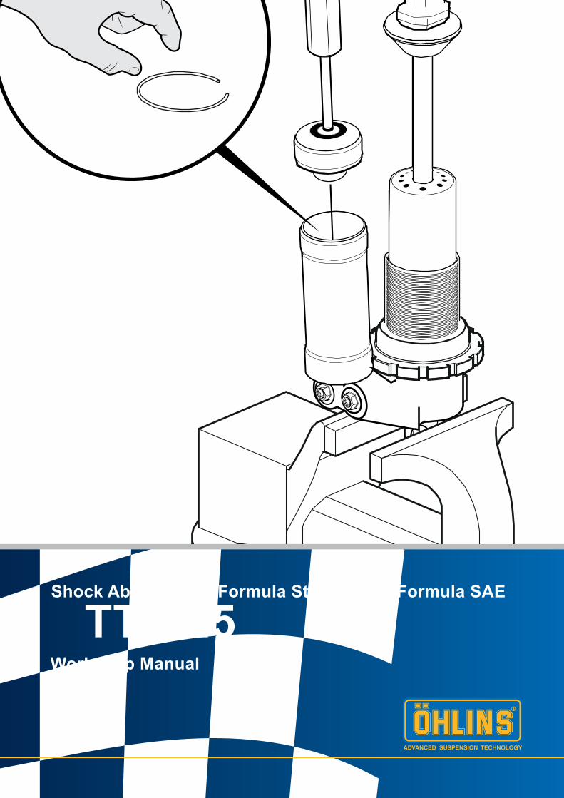
TTX 25Workshop Manual
Shock Absorber for Formula Student and Formula SAE
2
SAFETY PRECAUTIONS
© Öhlins Racing AB. All rights reserved. Any reprinting or unauthorized use without the written permission of Öhlins Racing AB is prohibited.
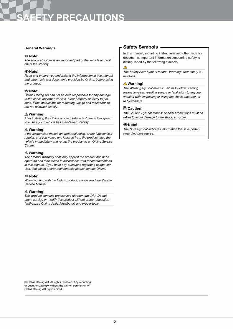
Safety SymbolsIn this manual, mounting instructions and other technical documents, important information concerning safety is distinguished by the following symbols:
The Safety Alert Symbol means: Warning! Your safety is involved.
Warning!The Warning Symbol means: Failure to follow warning instructions can result in severe or fatal injury to anyone working with, inspecting or using the shock absorber, or to bystanders.
Caution!The Caution Symbol means: Special precautions must be taken to avoid damage to the shock absorber.
Note!The Note Symbol indicates information that is important regarding procedures.
General Warnings
Note!The shock absorber is an important part of the vehicle and will affect the stability.
Note!Read and ensure you understand the information in this manual and other technical documents provided by Öhlins, before using the product.
Note!Öhlins Racing AB can not be held responsible for any damage to the shock absorber, vehicle, other property or injury to per-sons, if the instructions for mounting, usage and maintenance are not followed exactly.
Warning!After installing the Öhlins product, take a test ride at low speed to ensure your vehicle has maintained stability.
Warning!If the suspension makes an abnormal noise, or the function is ir-regular, or if you notice any leakage from the product, stop the vehicle immediately and return the product to an Öhlins Service Centre.
Warning!The product warranty shall only apply if the product has been operated and maintained in accordance with recommendations in this manual. If you have any questions regarding usage, ser-vice, inspection and/or maintenance please contact Öhlins.
Note!When working with the Öhlins product, always read the Vehicle Service Manual.
Warning!This product contains pressurized nitrogen gas (N2). Do not open, service or modify this product without proper education (authorized Öhlins dealer/distributor) and proper tools.
2 3
CONTENT
PageSAFETY PRECAUTIONS ����������������������������������������������������������������������������������������2TOOLS ��������������������������������������������������������������������������������������������������������������������41 - PRESSURE��������������������������������������������������������������������������������������������������������5
1�1 Depressurize ��������������������������������������������������������������������������������������������������51�2 Pressurize ������������������������������������������������������������������������������������������������������7
2 - REMOVE SHAFT ASSEMBLY ���������������������������������������������������������������������������83 - REPLACE END-EYE������������������������������������������������������������������������������������������9
3�1 Disassemble���������������������������������������������������������������������������������������������������93�2 Assemble������������������������������������������������������������������������������������������������������10
4 - REPLACE SEAL HEAD �����������������������������������������������������������������������������������114�1 Disassemble�������������������������������������������������������������������������������������������������114�2 Assemble������������������������������������������������������������������������������������������������������11
5 - REPLACE PISTON BAND �������������������������������������������������������������������������������125�1 Disassemble�������������������������������������������������������������������������������������������������125�2 Assemble������������������������������������������������������������������������������������������������������12
6 - REPLACE SEPARATING PISTON SEAL 136�1 Disassemble�������������������������������������������������������������������������������������������������136�2 Assemble������������������������������������������������������������������������������������������������������14
7 - CHANGE VALVE SPECIFICATION������������������������������������������������������������������157�1 Disassemble�������������������������������������������������������������������������������������������������157�2 Assemble������������������������������������������������������������������������������������������������������17
8 -OIL FILL PROCEDURE �������������������������������������������������������������������������������������18
4
TOOLS
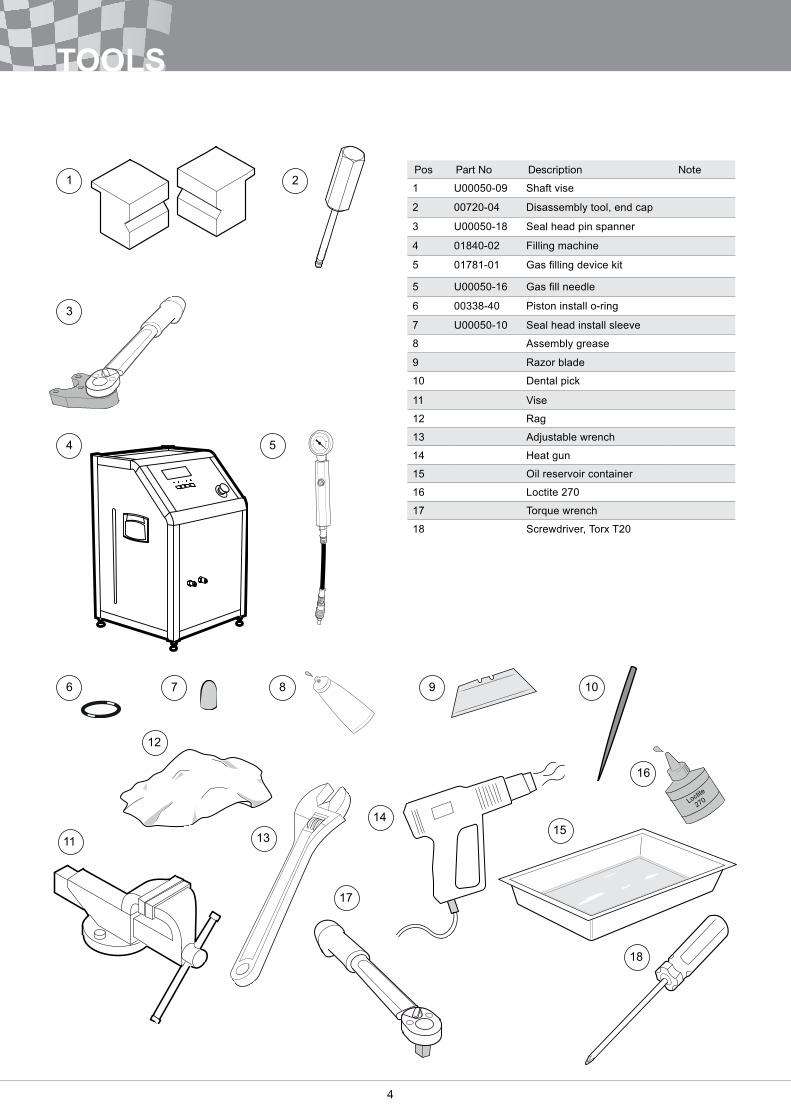
Pos Part No Description Note
1 U00050-09 Shaft vise
2 00720-04 Disassembly tool, end cap
3 U00050-18 Seal head pin spanner
4 01840-02 Filling machine
5 01781-01 Gas filling device kit
5 U00050-16 Gas fill needle
6 00338-40 Piston install o-ring
7 U00050-10 Seal head install sleeve
8 Assembly grease
9 Razor blade
10 Dental pick
11 Vise
12 Rag
13 Adjustable wrench
14 Heat gun
15 Oil reservoir container
16 Loctite 270
17 Torque wrench
18 Screwdriver, Torx T20
1 2
3
4 5
876 109
11 13
14
17
15
12
16
18
4 5
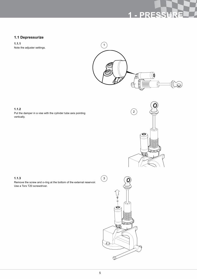
1.1 Depressurize1.1.1Note the adjuster settings�
1.1.2Put the damper in a vise with the cylinder tube axis pointing vertically�
1.1.3Remove the screw and o-ring at the bottom of the external reservoir� Use a Torx T20 screwdriver�
1
2
3
1 - PRESSURE
6
1 - PRESSURE
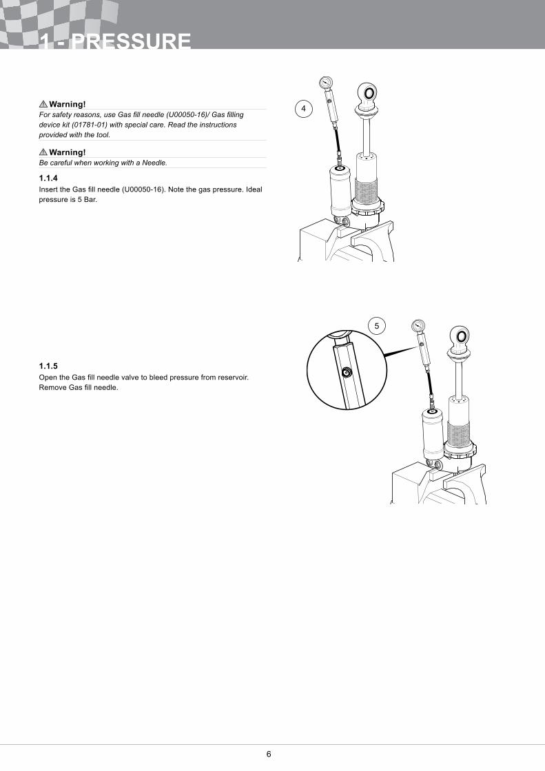
Warning!For safety reasons, use Gas fill needle (U00050-16)/ Gas filling device kit (01781-01) with special care. Read the instructions provided with the tool.
Warning!Be careful when working with a Needle.
1.1.4Insert the Gas fill needle (U00050-16). Note the gas pressure. Ideal pressure is 5 Bar�
1.1.5Open the Gas fill needle valve to bleed pressure from reservoir. Remove Gas fill needle.
4
5
6 7
1
2
1 - PRESSURE
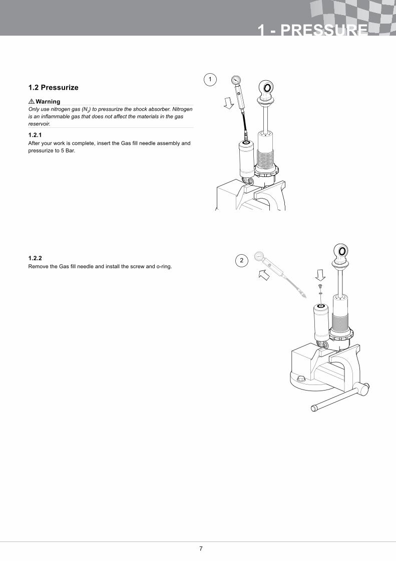
1.2 Pressurize
WarningOnly use nitrogen gas (N2) to pressurize the shock absorber. Nitrogen is an inflammable gas that does not affect the materials in the gas reservoir.
1.2.1After your work is complete, insert the Gas fill needle assembly and pressurize to 5 Bar�
1.2.2Remove the Gas fill needle and install the screw and o-ring.
8
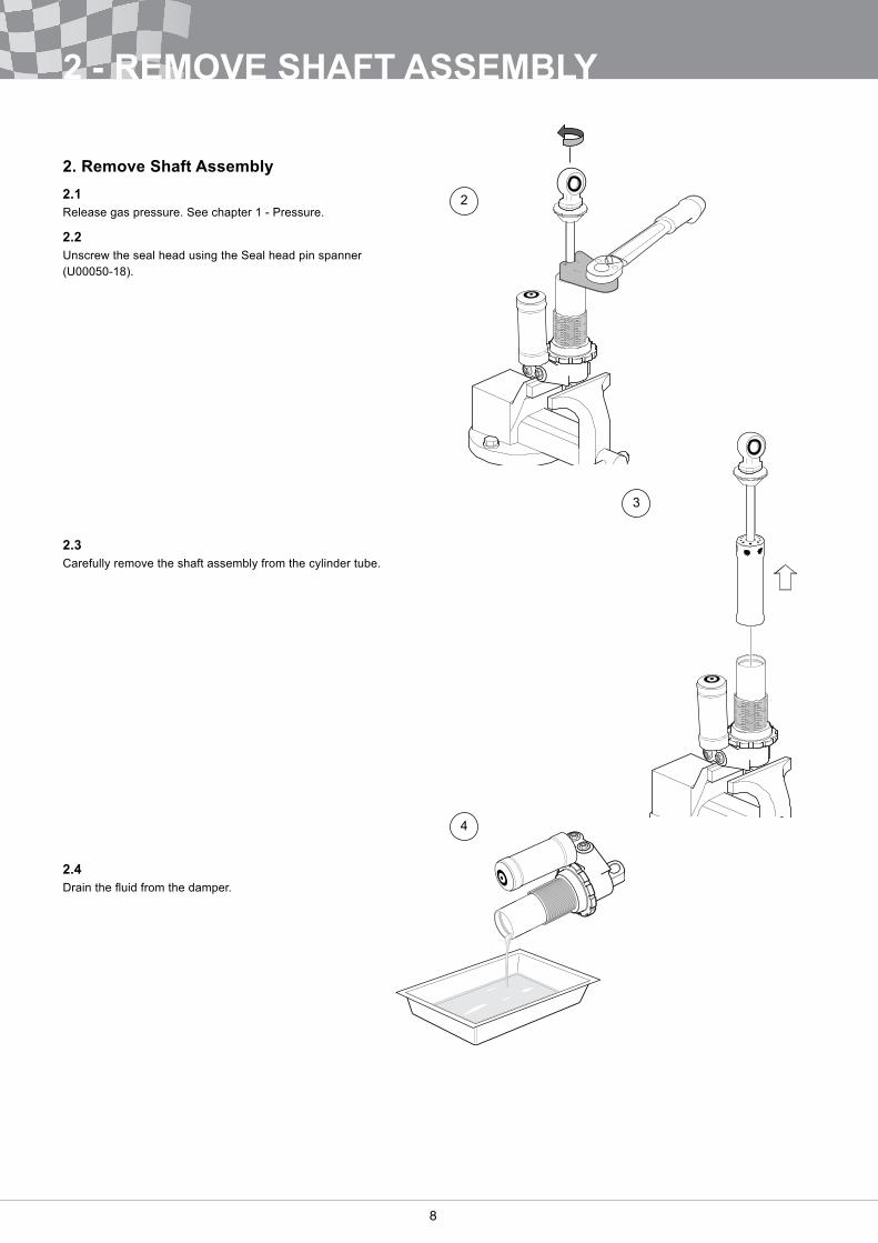
2. Remove Shaft Assembly2.1Release gas pressure� See chapter 1 - Pressure�
2.2Unscrew the seal head using the Seal head pin spanner (U00050-18).
2.3Carefully remove the shaft assembly from the cylinder tube�
2.4Drain the fluid from the damper.
2
3
4
2 - REMOVE SHAFT ASSEMBLY
8 9
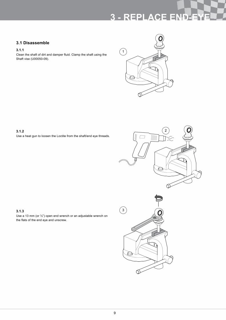
3.1 Disassemble3.1.1Clean the shaft of dirt and damper fluid. Clamp the shaft using the Shaft vise (U00050-09).
3.1.2Use a heat gun to loosen the Loctite from the shaft/end eye threads�
3.1.3Use a 13 mm (or ½”) open end wrench or an adjustable wrench on the flats of the end eye and unscrew.
3 - REPLACE END-EYE
1
2
3
10
3 - REPLACE END-EYE
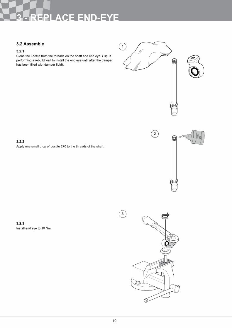
3.2 Assemble3.2.1Clean the Loctite from the threads on the shaft and end eye. (Tip: If performing a rebuild wait to install the end eye until after the damper has been filled with damper fluid).
3.2.2Apply one small drop of Loctite 270 to the threads of the shaft�
3.2.3Install end eye to 10 Nm�
1
2
3
10 11
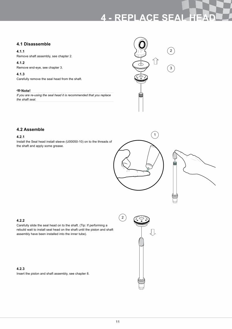
4.1 Disassemble4.1.1 Remove shaft assembly, see chapter 2�
4.1.2Remove end-eye, see chapter 3�
4.1.3Carefully remove the seal head from the shaft�
Note!
If you are re-using the seal head it is recommended that you replace the shaft seal.
4.2 Assemble4.2.1Install the Seal head install sleeve (U00050-10) on to the threads of the shaft and apply some grease�
4.2.2Carefully slide the seal head on to the shaft. (Tip: If performing a rebuild wait to install seal head on the shaft until the piston and shaft assembly have been installed into the inner tube).
4.2.3Insert the piston and shaft assembly, see chapter 8�
2
3
1
2
4 - REPLACE SEAL HEAD
12
5 - REPLACE PISTON BAND
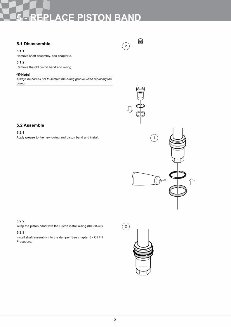
5.1 Disassemble5.1.1Remove shaft assembly, see chapter 2�
5.1.2Remove the old piston band and o-ring�
Note!Always be careful not to scratch the o-ring groove when replacing the o-ring.
5.2 Assemble5.2.1Apply grease to the new o-ring and piston band and install�
5.2.2Wrap the piston band with the Piston install o-ring (00338-40).
5.2.3Install shaft assembly into the damper� See chapter 8 - Oil Fill Procedure�
1
2
2
12 13
6 - REPLACE SEPARATING PISTON SEAL
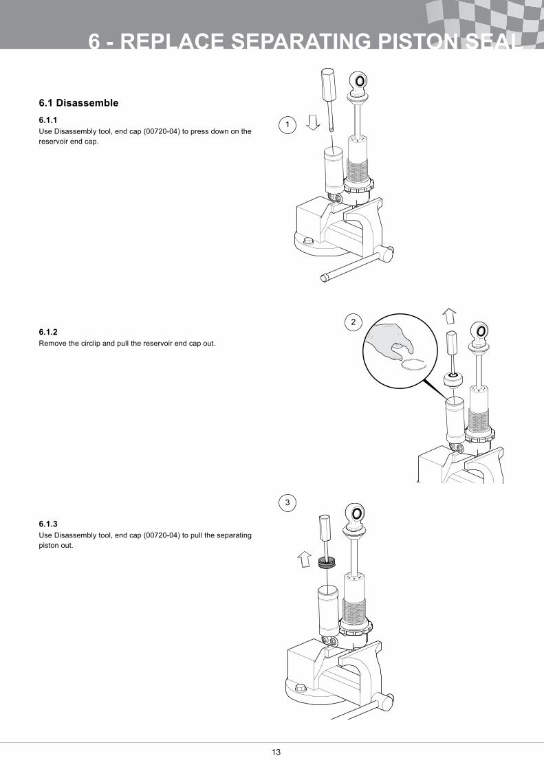
6.1 Disassemble6.1.1Use Disassembly tool, end cap (00720-04) to press down on the reservoir end cap�
6.1.2Remove the circlip and pull the reservoir end cap out�
6.1.3Use Disassembly tool, end cap (00720-04) to pull the separating piston out�
1
2
3
14
6 - REPLACE SEPARATING PISTON SEAL
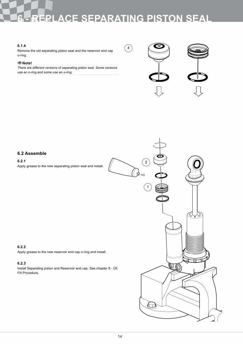
6.1.4Remove the old separating piston seal and the reservoir end cap o-ring�
Note!There are different versions of separating piston seal. Some versions use an o-ring and some use an x-ring.
6.2 Assemble6.2.1Apply grease to the new separating piston seal and install�
6.2.2Apply grease to the new reservoir end cap o-ring and install�
6.2.3Install Separating piston and Reservoir end cap� See chapter 8 - Oil Fill Procedure�
4
1
2
14 15
7 - CHANGE VALVE SPECIFICATION
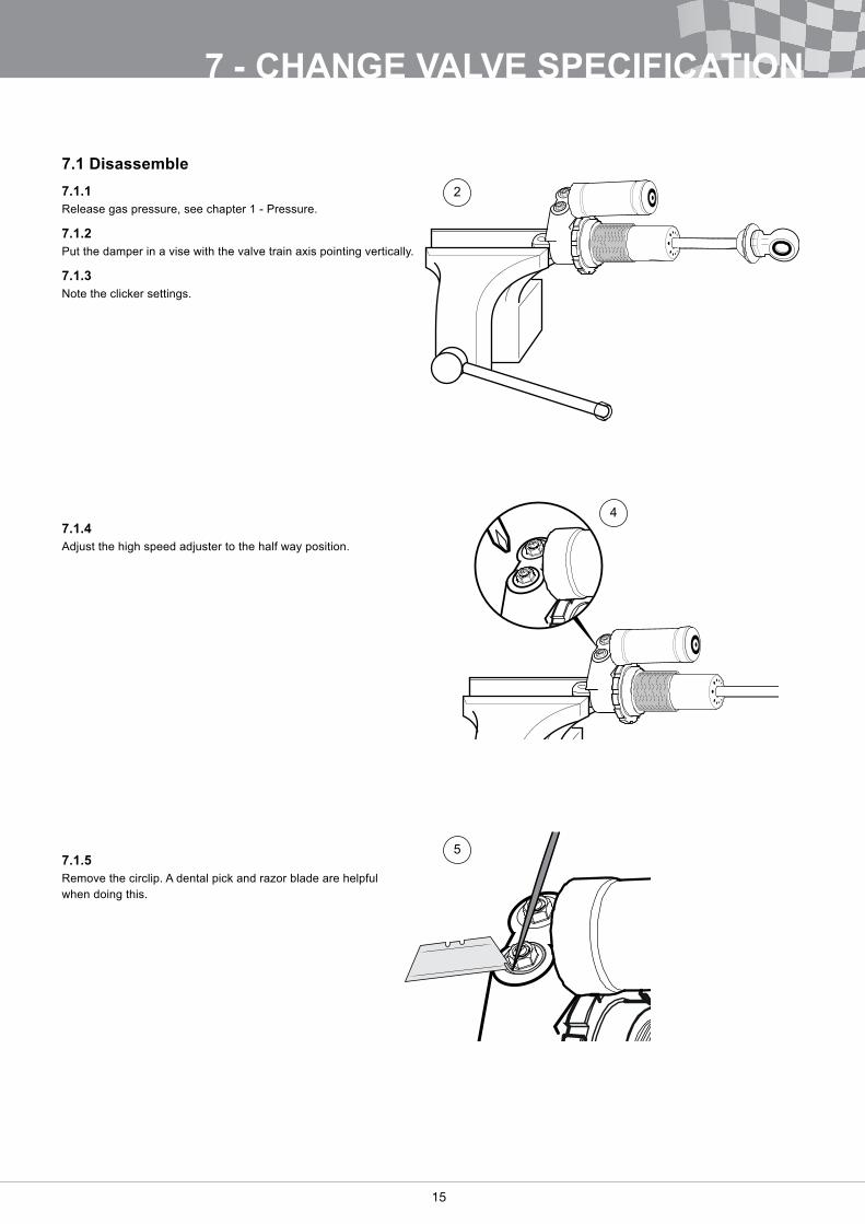
7.1 Disassemble7.1.1Release gas pressure, see chapter 1 - Pressure�
7.1.2Put the damper in a vise with the valve train axis pointing vertically�
7.1.3Note the clicker settings.
7.1.4Adjust the high speed adjuster to the half way position�
7.1.5Remove the circlip. A dental pick and razor blade are helpful when doing this�
2
4
5
16
7 - CHANGE VALVE SPECIFICATION
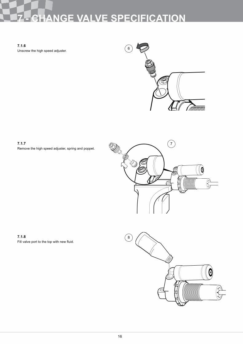
7.1.6Unscrew the high speed adjuster�
7.1.7Remove the high speed adjuster, spring and poppet�
7.1.8Fill valve port to the top with new fluid.
6
7
8
16 17
7 - CHANGE VALVE SPECIFICATION
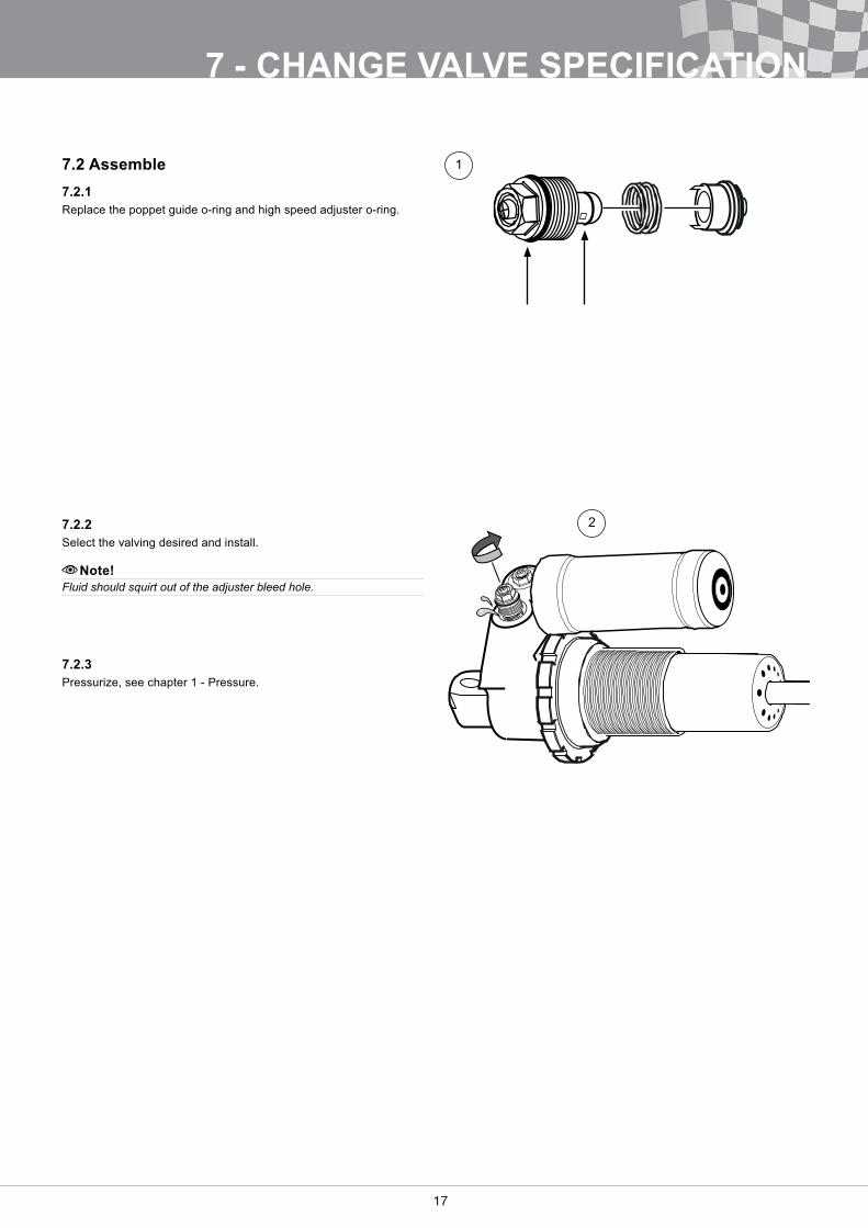
7.2 Assemble7.2.1Replace the poppet guide o-ring and high speed adjuster o-ring�
7.2.2Select the valving desired and install�
Note!Fluid should squirt out of the adjuster bleed hole.
7.2.3Pressurize, see chapter 1 - Pressure�
1
2
18
8 - OIL FILL PROCEDURE
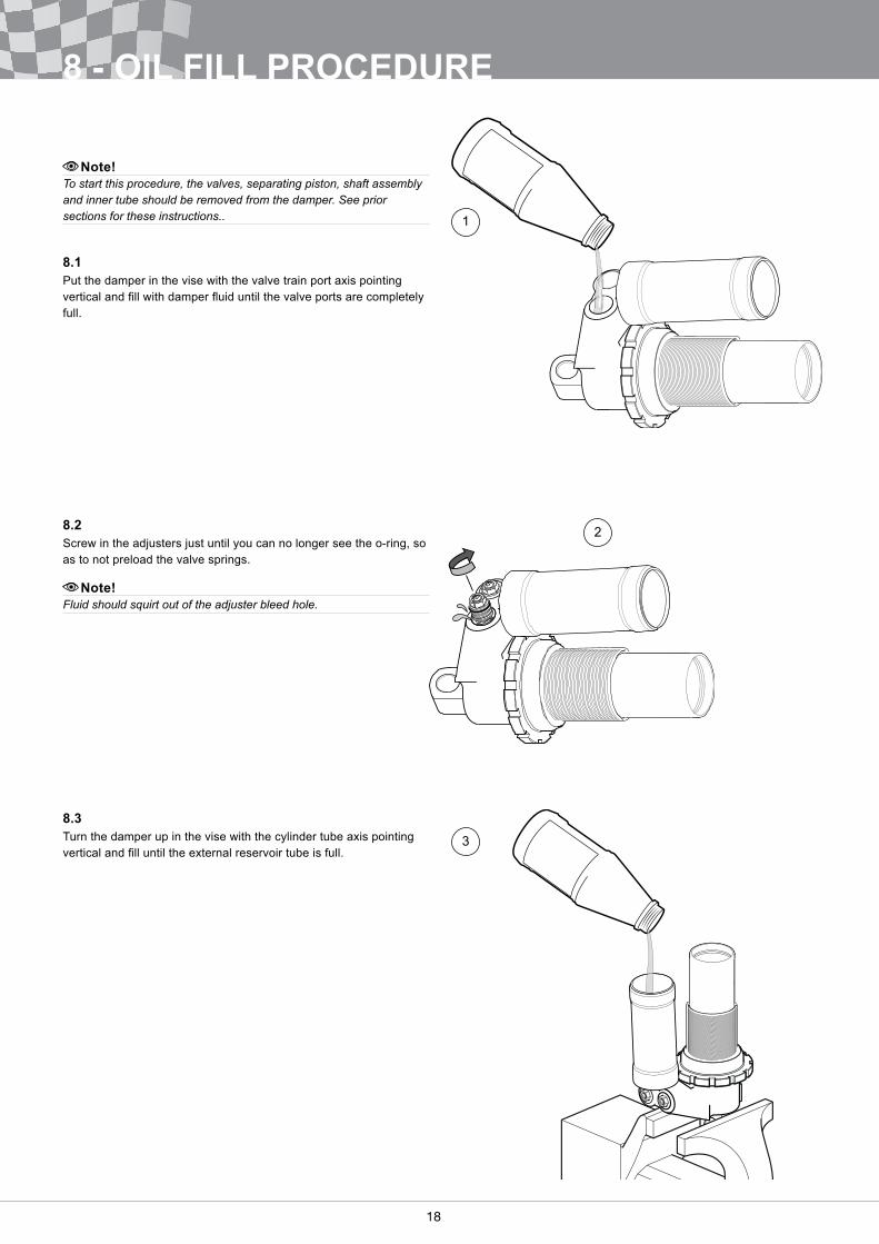
Note!To start this procedure, the valves, separating piston, shaft assembly and inner tube should be removed from the damper. See prior sections for these instructions..
8.1Put the damper in the vise with the valve train port axis pointing vertical and fill with damper fluid until the valve ports are completely full�
8.2Screw in the adjusters just until you can no longer see the o-ring, so as to not preload the valve springs�
Note!Fluid should squirt out of the adjuster bleed hole.
8.3Turn the damper up in the vise with the cylinder tube axis pointing vertical and fill until the external reservoir tube is full.
1
2
3
18 19
8 - OIL FILL PROCEDURE
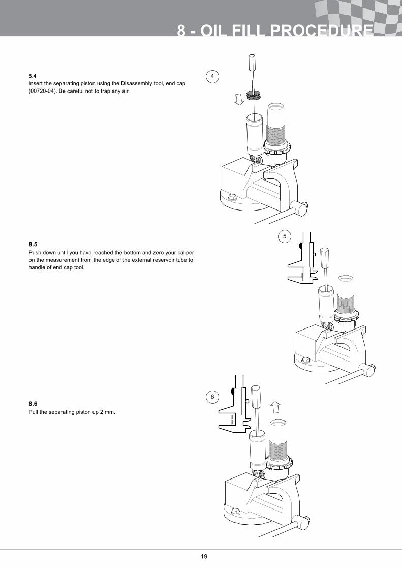
8�4 Insert the separating piston using the Disassembly tool, end cap (00720-04). Be careful not to trap any air.
8.5Push down until you have reached the bottom and zero your caliper on the measurement from the edge of the external reservoir tube to handle of end cap tool�
8.6Pull the separating piston up 2 mm�
4
5
6
20
8 - OIL FILL PROCEDURE
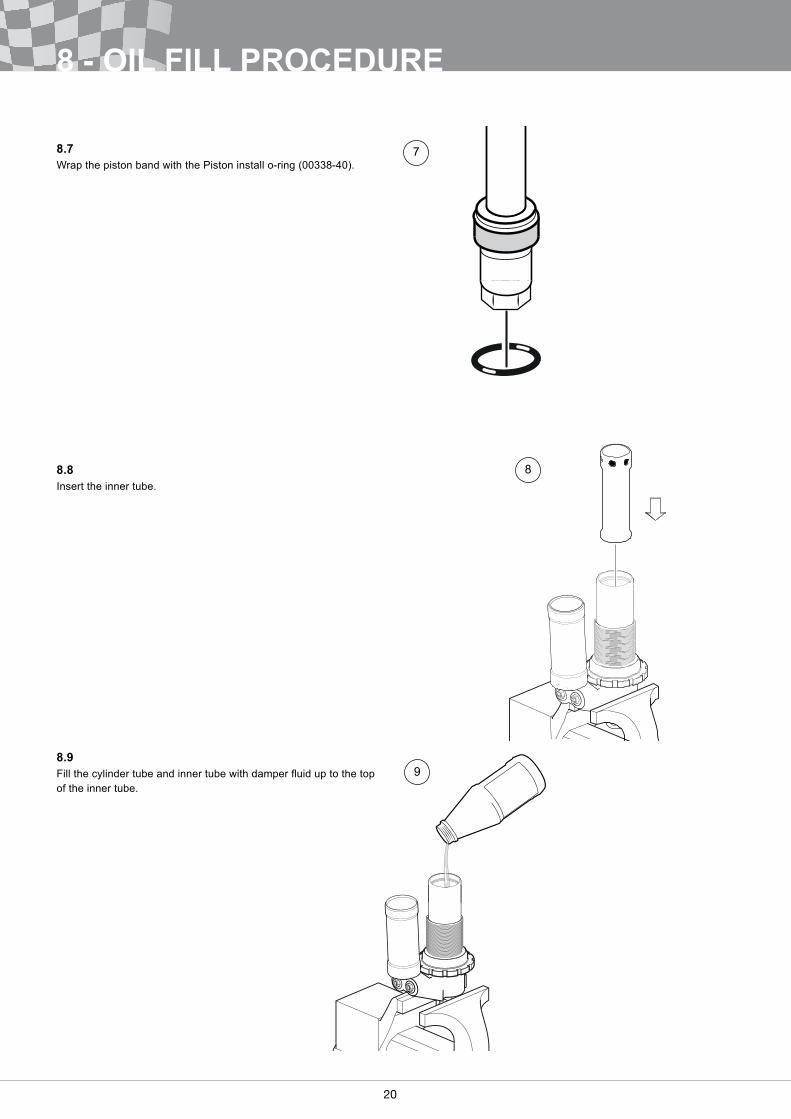
8.7Wrap the piston band with the Piston install o-ring (00338-40).
8.8Insert the inner tube�
8.9Fill the cylinder tube and inner tube with damper fluid up to the top of the inner tube�
7
8
9
20 21
8 - OIL FILL PROCEDURE
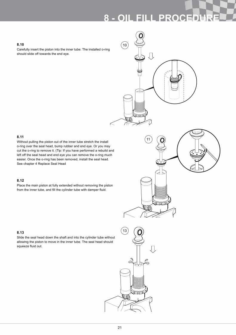
8.10Carefully insert the piston into the inner tube� The installed o-ring should slide off towards the end eye�
8.11Without pulling the piston out of the inner tube stretch the install o-ring over the seal head, bump rubber and end eye� Or you may cut the o-ring to remove it. (Tip: If you have performed a rebuild and left off the seal head and end eye you can remove the o-ring much easier� Once the o-ring has been removed, install the seal head� See chapter 4 Replace Seal Head
8.12Place the main piston at fully extended without removing the piston from the inner tube, and fill the cylinder tube with damper fluid.
8.13Slide the seal head down the shaft and into the cylinder tube without allowing the piston to move in the inner tube� The seal head should squeeze fluid out.
11
13
10
22
8 - OIL FILL PROCEDURE
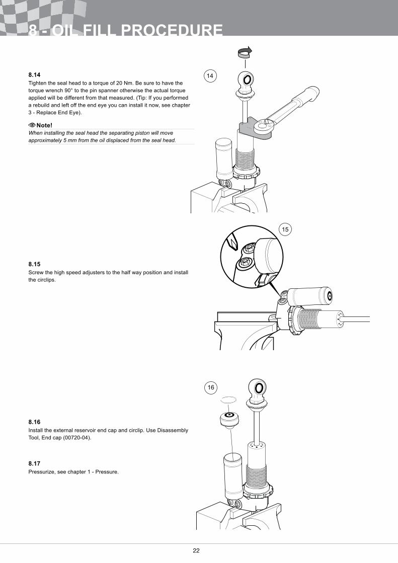
8.14Tighten the seal head to a torque of 20 Nm� Be sure to have the torque wrench 90° to the pin spanner otherwise the actual torque applied will be different from that measured. (Tip: If you performed a rebuild and left off the end eye you can install it now, see chapter 3 - Replace End Eye).
Note!When installing the seal head the separating piston will move approximately 5 mm from the oil displaced from the seal head.
8.15Screw the high speed adjusters to the half way position and install the circlips�
8.16Install the external reservoir end cap and circlip� Use Disassembly Tool, End cap (00720-04).
8.17Pressurize, see chapter 1 - Pressure�
14
15
16
22 23
[This page is intentionally left blank.]
Your Öhlins retailer:
Öhl
ins
Wor
ksho
p M
anua
l TTX
25Fo
rmul
aStu
dent
/SA
E_0
| Is
sued
201
3-03
-18
| © Ö
hlin
s R
acin
g A
B
Phone: +46 (0)8 590 025 00Fax: +46 (0)8 590 025 80
www.ohlins.com
Öhlins Racing ABBox 722SE-194 27, Upplands VäsbySweden