Embed Size (px)
Citation preview

WO
RK
SH
OP
MA
NU
AL
100
cm3
Moteur FB3 - FB6
GB

100cm3 1
This workshop manual concerns the FB engine which is fitted on several 100cm³vehicles
- FB 3………..SV100- FB 6………..SPEEDFIGHT - TREKKER - ELYSÉO - VIVACITY
2-stroke oil
2T SPECIAL ................................... 1.... litre .... Ref. 753752
2T SYNTETIC................................. 1.... litre .... Ref. 753759
Relay box oil
GEAR OIL GX-80W-90 .................. 2.... litres .. Ref.753009
High temperature grease
SKF LGHT 3/0.4................................................ Ref. 752093
- A GOOD MECHANIC WORKS IN AN ORDERLY AND METHODICALFASHION- TIME SAVING = MONEY SAVING
INTRODUCTION

100cm32
INTRODUCTION
page.................................................................... 1
CHARACTERISTICS
Vivacity ............................................................... 3Elyséo ................................................................. 4Speedfight .......................................................... 5TKR .................................................................... 5SV100 ................................................................. 6
MAINTENANCE PLAN
page.................................................................... 7
SETTING UP
page.................................................................... 8
TIGHTENING TORQUE AND SPECIALTOOLS
page.................................................................... 9
CONTENTS
DISMANTLING AND REASSEMBLYPROCEDURE
Of the engine from the vehicle.......................... 10Placing the engine on its support ..................... 10Of the cooling system ....................................... 10Of the flywheel ................................................... 11Of the cylinder headAnd the cylinder – piston assembly .................. 12Of the cylinder and the piston ........................... 12Of the intake valve and pipe ............................. 13Of the primary transmission assy ..................... 13Of the kick starter system ................................. 15Of the relay ....................................................... 16Of the oil pump ................................................. 17Setting the oil pump .......................................... 17Checking the lubrication circuit ......................... 17Of the starter..................................................... 18Of the carburettor - choke assy ........................ 18Opening of engine housings ............................. 19Of the crankshaft assy ...................................... 20Checking the crankshaft assy ........................... 20Replacing the bearings and seals .................... 21Engine reassembly and closing of housings .... 21

100cm3
oiloil0,1
2L0,1
2L
3
ENGINE MARKING
NumberType
XXXXXXXXFB6
IDENTIFICATION MARKING
VIN number (17 characters)
Manufacturer’splate
VIVACITY
- FB6 ENGINE2 stroke cooled by forced airBore x stroke ...................................................... 50.6 X 49.7Displacement ........................................................... 100 cm³Gross compression ratio ................................................... 11
- Maximum power :............................................. 6.4 kw at 7000 rpm (95/1/CEE)
- Timing :Exhaust ......................................................................... 184°Transfer ......................................................................... 124°Intake .......................................................................by valve
- Ignition :Advance ........................................ mapping 17° before TDCSpark plug ...................................................... resistive 5 KΩ......................................................................... NGK BR8ES.................................................................EYQUEM R1000LSpark gap ................................................................. 0.6 mm
- Carburettor :.................................................. DELL’ORTO PHVA 17.5 ESIdling speed ................................................. 1 600 rpm +100Initial position of the air screw ....................... loosen : 2 turns5-notch needle ............................ A10 4th notch from the topMain jet ............................................................................. 83Idling jet ........................................................................... 32
- Flywheel : ............................................ MITSUBA- Starter : ............................................... MITSUBA- Oil pump : ............................................... MIKUNI
CHARACTERISTICS
Main characteristics
Identification : VGAS2AC . . . . . . . . . .
Front tyre ............................................................. 120/70 -12Rear tyre ............................................................... 130/70-12Pressure when cold : front ..................................... 1.3 bar
rear ...................................... 1.6 bar
Capacities (litre)
Fuel tank............................................................................. 6Oil tank ............................................................................ 1.3Relay box ...................................................................... 0.12
Dimensions (mm)
Overall length ...............................................................1 740Overall width (not including mirrors) ............................... 697Overall height (not including mirrors) ............................1 143
Wheelbase .....................................................................1 249
Weight (kg)
Dry weight ......................................................................... 90Weight with full tanks ........................................................ 98
Markings 100 cm³
LH housing (under the starter)Cylinder head (front RH side)Cylinder (exhaust bracket LH side)Intake pipe Ø19.5
Transmission
Clutch .......................................... centrifugal, automatic typePrimary transmission ................................. by notched V-beltReduction gear .......................... with 2 trains of gear-wheels
Chassis
100cm3
ENGINE MARKING
NumberType
XXXXXXXXFB6 VIN number (17 characters)
4
oiloil0,1
2L0,1
2L
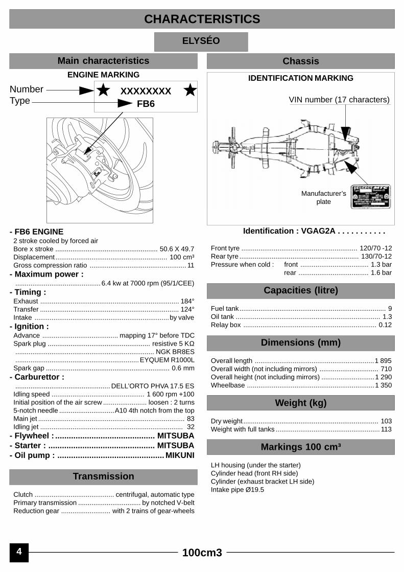
ELYSÉO
Identification : VGAG2A . . . . . . . . . . .
Front tyre ............................................................. 120/70 -12Rear tyre ............................................................... 130/70-12Pressure when cold : front .................................... 1.3 bar
rear ..................................... 1.6 bar
Capacities (litre)
Fuel tank............................................................................. 9Oil tank ............................................................................ 1.3Relay box ...................................................................... 0.12
Dimensions (mm)
Overall length ...............................................................1 895Overall width (not including mirrors) ............................... 710Overall height (not including mirrors) ............................1 290Wheelbase ...................................................................1 350
Weight (kg)
Dry weight ....................................................................... 103Weight with full tanks ....................................................... 113
Markings 100 cm³
LH housing (under the starter)Cylinder head (front RH side)Cylinder (exhaust bracket LH side)Intake pipe Ø19.5
Main characteristics
IDENTIFICATION MARKING
Manufacturer’splate
CHARACTERISTICS
Chassis
- FB6 ENGINE2 stroke cooled by forced airBore x stroke ...................................................... 50.6 X 49.7Displacement ........................................................... 100 cm³Gross compression ratio ................................................... 11
- Maximum power :............................................. 6.4 kw at 7000 rpm (95/1/CEE)
- Timing :Exhaust ......................................................................... 184°Transfer ......................................................................... 124°Intake .......................................................................by valve
- Ignition :Advance ........................................ mapping 17° before TDCSpark plug ...................................................... resistive 5 KΩ......................................................................... NGK BR8ES.................................................................EYQUEM R1000LSpark gap ................................................................. 0.6 mm
- Carburettor :.................................................. DELL’ORTO PHVA 17.5 ESIdling speed ................................................. 1 600 rpm +100Initial position of the air screw ....................... loosen : 2 turns5-notch needle .............................A10 4th notch from the topMain jet ............................................................................. 83Idling jet ........................................................................... 32
- Flywheel : ............................................ MITSUBA- Starter : ............................................... MITSUBA- Oil pump : ............................................... MIKUNI
Transmission
Clutch .......................................... centrifugal, automatic typePrimary transmission ................................. by notched V-beltReduction gear .......................... with 2 trains of gear-wheels

100cm3 5
TKR / FIGHT
ENGINE MARKING
NumberType
XXXXXXXXFB6
IDENTIFICATION MARKING
VIN number (17 characters)
Manufacturer’splate
oiloil0,1
2L0,1
2L
Identification : TKR : VGAS2AA . . . . . . . . . .Identification : FIGHT : VGAS2AB . . . . . . . . . .
Front tyre .............................................................. 120/70-12Rear tyre .................................................... 130 ou 140/70-12Pressure when cold :FIGHT : front .................................... 1.6 bar
rear ..................................... 1.8 barTKR : front .................................... 1.3 bar
rear ..................................... 1.6 bar
Capacities (litre)
Fuel tank TKR .................................................................... 6Fuel tank FIGHT ................................................................. 7Oil tank ............................................................................ 1.3Relay box ...................................................................... 0.12
Dimensions (mm)
TKR FIGHTOverall length ............................................... 1 760 ..... 1730Overall width (not including mirrors) ............... 670 ....... 700Overall height (not including mirrors) .............. 1110 ...... 1155Wheelbase .................................................... 1250 ..... 1225
Weight (kg)
TKR FIGHTDry weight .......................................................... 89 ......... 94Weight with full tanks ......................................... 94 ....... 101
Markings 100 cm³
LH housing (under the starter)Cylinder head (front RH side)Cylinder (exhaust bracket LH side)Intake pipe Ø19.5
Main characteristics
CHARACTERISTICS
Chassis
- FB6 ENGINE2 stroke cooled by forced airBore x stroke ...................................................... 50.6 X 49.7Displacement ........................................................... 100 cm³Gross compression ratio ................................................... 11
- Maximum power :............................................. 6.4 kw at 7000 rpm (95/1/CEE)
- Timing :Exhaust ......................................................................... 184°Transfer ......................................................................... 124°Intake .......................................................................by valve
- Ignition :Advance ........................................ mapping 17° before TDCSpark plug ...................................................... resistive 5 KΩ......................................................................... NGK BR8ES.................................................................EYQUEM R1000LSpark gap ................................................................. 0.6 mm
- Carburettor :............................................................ DELL’ORTO 17.5 ESIdling speed ................................................. 1 600 rpm +100Initial position of the air screw ....................... loosen : 2 turns5-notch needle ............................ A11 2nd notch from the topMain jet ............................................................................. 81Idling jet ............................................................................ 32
- Flywheel : ............................................ MITSUBA- Starter : ............................................... MITSUBA- Oil pump : ............................................... MIKUNI
Transmission
Clutch .......................................... centrifugal, automatic typePrimary transmission ................................. by notched V-beltReduction gear .......................... with 2 trains of gear-wheels

100cm36
SV100
ENGINE MARKING
NumberType
XXXXXXXXFB3
IDENTIFICATION MARKING
Chassis Number
Manufacturer’splate
oiloil0,1
2L0,1
2L
Identification : 035 . . . . . . .Front tyre .............................................................. 100/90-10Rear tyre ............................................................... 100/90-10Pressure when cold : front .................................... 1.8 bar
rear ..................................... 2.2 bar
Capacities (litre)
Fuel tank.......................................................................... 8.8Oil tank ............................................................................ 1.1Relay box ...................................................................... 0.12
Dimensions (mm)
Overall length ............................................................... 1800Overall width (not including mirrors) .............................. 715Overall height (not including mirrors) ............................. 1190Wheelbase ................................................................... 1260
Weight (kg)
Dry weight ......................................................................... 88Weight with full tanks ........................................................ 99
Markings 100 cm³
LH housing (under the starter)Cylinder head (front RH side)Cylinder (exhaust bracket LH side)Intake pipe Ø19.5
Main characteristics
CHARACTERISTICS
Chassis
- FB3 ENGINE2 stroke cooled by forced airBore x stroke ...................................................... 50.6 X 49.7Displacement ........................................................... 100 cm³Gross compression ratio ................................................... 11
- Maximum power :............................................. 6.4 kw at 7000 rpm (95/1/CEE)
- Timing :Exhaust ......................................................................... 184°Transfer ......................................................................... 124°Intake .......................................................................by valve
- Ignition :Advance ........................................ mapping 17° before TDCSpark plug ...................................................... resistive 5 KΩ......................................................................... NGK BR8ES.................................................................EYQUEM R1000LSpark gap ................................................................. 0.6 mm
- Carburettor :.................................................. DELL’ORTO PHVA 17.5 ESIdling speed ................................................. 1 600 rpm +100Initial position of the air screw ....................... loosen : 2 turns5-notch needle ............................ A11 2nd notch from the topMain jet ............................................................................. 76Idling jet ............................................................................ 34
- Starter : ............................................... MITSUBA- Oil pump : ............................................... MIKUNI- Flywheel : ............................................ MITSUBA
Transmission
Clutch .......................................... centrifugal, automatic typePrimary transmission ................................. by notched V-beltReduction gear .......................... with 2 trains of gear-wheels

100cm3
PLAN C
CHECK :Setting of idling speed X X XThrottle control X X XControl of oil pump X X XFunctioning of the electrical equipment X X XControl of front and rear brake X X XFuel pipes X X XOil pipes X X XFront brake fluid pipes X X XState and pressure of tyres XState, pressure and wear of tyres X XBrake fluid level X X XLevel of battery electrolyte X X X(depending on type of battery)Tightening of nuts and bolts X X X
CHANGE :Relay box oil X XSpark plug X XFilter component of intake silencer X XFront brake pads (if necessary) XRear brake linings or pads (if necessary) X XDrive pulley rollers (if necessary) X XTiming belt X
CHECK AND DECARBONISE :Piston XCylinder head XExhaust port X
CHECK AND LUBRICA TE :Driven pulley : Movable driven face and needle bearing XDrive pulley : Movable drive face and rollers XKick : driven gear and spindle pin bush XCentral and lateral kick stand pivot bolt(if fitted) XRear brake cam X
CLEAN AND ADJUST :Carburettor X
VEHICLE TEST :On road X X X
PLAN A PLAN B500 km or 3 mois 2500 km* or 5000 km 5000 km* or 10000 km
* Reinforced maintenance
7
Depending on the use of the scooter, it is recommended to apply - the normal maintenance plan or- the reinforced maintenance plan
The normal maintenance plan includes :-Visit after 500 km or 3 months Plan A-Regular servicing every 5000 km Plan B- Regular servicing every 10000 km Plan C
The reinforced maintenance plan includes :- Visit after 500 km Plan A- Regular servicing every 2500 km Plan B- Regular servicing every 5000 km Plan C
Reinforced maintenance applies to vehicles used in so-called “severe” conditions: door to door, intensive urban use (courier),short journeys with engine cold, regions with dusty atmospheres, frequent use of vehicles in ambient temperatures over 30°C.
MAINTENANCE PLAN

100cm38
1. Preparation of the battery
Charging a dry battery:- Remove the battery- Remove the six filling caps and the air vent cap- Fill with electrolyte (35 % sulphuric acid = 1.28 g / cm³) up to
the level marked UPPER LEVELReference .......................................... 1 litre ..........752740
.......................................... 5 litres ........752741- Leave the battery to settle for half an hour. Top up the level
if necessary- Charge the battery for at least 2 hours, using an intensity of
400 m.A (0.4 A)- Replace the battery and connect the vapour breather hose
to it- Connect the red wire terminal to and the earth pin,
green wire to- From then on, the battery level should be maintained if
necessary using distilled water only
Battery without maintenance :- After carrying out the initial setting up operations in
accordance with the instructions manual enclosed with thevehicle, it should be noted that the cap ramp must not now beremoved
- Charging is carried out in normal mode at 0.5A during 5 to10 hours or at 5A during 30 minutes maximum in rapid chargemode
SETTING UP
6. Checks before delivery to customer
- In particular, check tightening of wheel nutsfront ......................................................................... 6 m.daNrear ........................................................................ 10 m.daN- Check tightening of nuts and bolts- Check brake adjustment and efficiency- Check inflation pressure of tyres when cold
- Check that lights and indicators are working properly (rearlight, indicators, brake light, horn unit), and various telltales
- Carry out road test with vehicle.
5. Checking the oil level in the relay box
- Vehicle on its stand and on a horizontal plane- Loosen and remove the filling screw and make sure that the
oil level reaches the filling orificeCapacity ................................................................... 0.12 litre
- Esso Gear Oil GX 80 W 90Reference ....................................................................753009
- Tighten the screw to 1.2 m.daN
4. Setting up the fuel and oil circuits
- Put one litre of mixture with 3 % oil in the fuel tank- Fill up the oil tank- Start the engine: check and ensure that the oil circuit is
perfectly primed- To do this, disconnect the oil intake hose at the carburettor
and check that oil drips out (frequency will depend on thespeed of rotation of the engine)
- Top up the fuel tank with high octane petrol
3. Separate lubrication
- Capacity .................................................................. 1.3 litre- Fill the oil tank with semi-synthetic or synthetic oil for 2-
stroke separate lubrication engines in accordance with thestandards ....................................... API ................. type TC
....................................... JASO ............. type FC- PEUGEOT MOTOCYCLES recommends :................................................................. ESSO 2T Special............................................................. ESSO 2T Synthetic
2. Fuel
- Capacity ............................................ depending on vehicle- To ensure the engine is in good working order use only lead
free 98 petrol or 95 for vehicles equipped with catalyticconverters and conventional 4-star or lead free 98 - 95 for theothers
TYPE Front RearSV100 .......................................................... 1,8 ........ 2,2TKR .............................................................. 1,3 ........ 1,6SPEEDFIGHT .............................................. 1,6 ........ 1,8Elyséo........................................................... 1,3 ........ 1,6Vivacity ......................................................... 1,3 ........ 1,6
+-

100cm3 9
Engine part
Assembly screws for :- Housing ................................................ 1 m.daN- Covers .................................................. 1 m.daN- Intake pipe ............................................ 1 m.daN- Starter ................................................... 1 m.daN- Stator .................................................... 1 m.daN- Sensor .................................................. 1 m.daN- Ventilator .............................................. 1 m.daN- Carburettor ........................................ 0.8 m.daN- Oil pump ............................................ 0.8 m.daN- Cylinder head .................................... 1.2 m.daN- Drive pulley ........................................... 4 m.daN- Driven pulley ...................................... 4.5 m.daN- Rotor ..................................................... 4 m.daN- Oil cap ............................................... 1.2 m.daN- Spark plug ............................................ 2 m.daN
Cycle part
- Front wheel nut .................................. 8.5 m.daN- Front wheel axle nut .......................... 7.5 m.daN- Rear wheel nut ................................... 10 m.daN- Engine on bracket link .......................... 6 m.daN- Bracket on chassis articulation ............. 6 m.daN- Upper shock absorber fastening Fr/Rr . 4 m.daN- Lower shock absorber fastening Fr/Rr2.2 m.daN- Exhaust nuts on cylinder ................... 1.6 m.daN- Handlebar nut ....................................... 4 m.daN- Steering lock-nut ............................... 6.5 m.daN- Suspension arm pivot pin ..................... 9 m.daN- Front brake reaction bracket ............. 5.6 m.daN- Front brake calliper ............................... 3 m.daN
- Screw and nut f 5 mm ...................... 0.5 m.daN- Screw and nut f 6 mm ......................... 1 m.daN- Screw and nut f 8 mm ...................... 2.2 m.daN- Screw and nut f 10 mm .................... 3.5 m.daN- Screw and nut f 12 mm .................... 5.5 m.daN
TIGHTENING TORQUE AND SPECIAL TOOLS
Tightening torques Special tools
- Engine support ......................................... 64765- Adjustable adaptation for engine support 752026- Flywheel clamp......................................... 68570- Piston circlip gripper ............................... 752000- Protective end piece small model for flywheel
puller ............................................................ 68007- Tool for removing and opening housing ... 64706- Protective end piece large model for opening
housing ......................................................... 69098- Retaining dowel pin .................................. 64710- Screw on torque handle ........................... 69104- Clutch compression tool all types ........... 752127- Tubular socket wrench 39 ...................... 752361- Adjustable notched wrench .................... 752237- (Half shells for extraction of bearing f 56)- Tool for opening housing ........................ 750807- Support washer ...................................... 750808- Base plate 250 X 160 X 50 ..................... 750541- Torque wrench + extension + reducer ...... 69802- Flywheel puller (delivered with protector 68007).................................................................. 750806- Immobilising tool ..................................... 752370- Circlip ........................................................69117- Spindle ................................................... 750069

100cm310
Removing the engine from the vehicle
- Remove :. all the lateral fairings.
- Disconnect :. the fuel intake pipe at carburettor,. the vacuum hose of the automatic cock assy,. the oil pump control,. the throttle control,. the oil intake pipe at the pump (big hose),. interference suppressor,. the rear brake control.
- Disconnect :. the electrical harness on the right hand tube of the
chassis : flywheel outlet (under the footboard), choke, starter.- Remove :
. the lower shock absorber fastening nut and the frontfastening pin of the engine.
DISMANTLING AND REASSEMBLY PROCEDURE
Placing the engine on its support
- Position the engine on the adapted part ref. 752026modified,
- Place the assembly on the support ref. 64765 clamped in avice.
Cooling system
- Remove the two parts of the cooling scroll (4 screws),- Tightening torque : 1 m.daN,

100cm3 11
750806
68007
752237Flywheel
- Immobilise the rotor using the notched clamp ref. 752237,- Remove the nut.
- Place the protective end piece ref. 68007 on the end of thecrankshaft,
- Screw the flywheel puller ref. 750806 onto the rotor andpress on the flywheel push screw until the rotor is freed,
- Remove the cotter pin,
- Remove the 2 fastening screws of the sensor, as well as the2 fastening screws on the stator plate : . 2 screws L=16
. 2 screws L=20),- Tightening torque : 1 m.daN,- Remove the stator assy and the sensor.
- Remove the 4 fastening screws from the turbine andremove it,
- Tightening torque : 1 m.daN.

100cm312
Cylinder and piston
- Check that the cylinder/piston assembly is correctly paired,
Note :There is a specific way up for assembling the piston rings:
chamfer at the top
- The mating face must be cleaned,- Place a new and dry base seal on the cylinder,- Place the needle bearing cage in the small end of the
conrod after having lubricated it (2-stroke oil),- Introduce the piston with the arrow pointing towards the
exhaust,- Push the piston pin,- Assemble the snap ring(s). They (it) must be new,- Oil the piston and the cylinder barrel,- Make sure that the opening of the piston rings is opposite
the positioning lugs,- Insert the cylinder and lower it whilst compressing the piston
rings between the middle finger and thumb,- Ensure that the base seal is correctly positioned on the
housing using the 2 stud bolts,- Place the cylinder head - screw - seal onto the cylinder.
Note :Bead of the seal against this
- Progressively tighten the 4 screws diagonally,- Tightening torque : 1.2 m.daN.
Cylinder head and cylinder – piston assy
- Loosen diagonally the 4 fastening screws of the cylinderhead-cylinder assembly,
- Remove the cylinder head and the seal,- Remove the cylinder and the base seal,- Lean the engine to the left and remove the RH circlip on the
piston,- Push the piston pin from left to right; this operation does not
necessitate the use of a strap,- Remove the needle bearing cage from the small end of the
conrod.

100cm3
752370
13
Intake pipe and valve
- Loosen and remove the 4 fastening screws, (L = 28mm),- Tightening torque : 1 m.daN.
- Remove the pipe, seal, valve assembly, second seal,-Check the state of the blades and seats.
Primary transmission assembly
Removal of the cover does not require the kick starter pedal tobe dismantled,
- Loosen and remove the 11 fastening screws from the cover,- Tightening torque : 1 m.daN,- Remove the cover with the 2 centring holes,- Remove the starter drive assy assembly,
- Block the fixed drive face-kick driven gear with the toolref. 752370,
Take careful note of the flush fitting of this tool with the fixeddrive face- kick driven gear so as to make sure that the fixeddrive face is correctly engaged in the grooves of the crankshaftwhen re-assembling,
- Loosen the fastening nut from the fixed drive face of thedrive pulley,
- Tightening torque : 4 m.daN,- Remove the nut and the fixed drive face,

100cm3
752237
14
- Remove the belt,- Take out the drive pulley assembly (variator),
Warning : Do not discard any stacking component , or reduce any of thedimensions as this could cause tightening of the nut on thegrooves of the crankshaft as opposed to the fixed drive face,which could lead to possible destruction of the crankshaft.
- Remove the drive face boss and the 3 screws holding downthe cover and the stop plate,
- Remove the cover using a screwdriver,- Remove the stop plate , the ramp, the 3 plastic guides, the
6 rollers and the “ O ” ring,- After cleaning, pay particular attention to the rollers; they
must not contain any significant wear traces.
Re-assembly
- Same operations as for dismantling in reverse order afterhaving lubricated the 6 rollers, the ramp and the bore of themovable drive face using high temperature greaseref. 752093,
- Block the clutch plate with the flywheel clampref. 68570, or the notched wrench ref. 752237,
- Loosen the nut, remove the drum and the clutch drivenpulley assembly,
- Tightening torque : 4 m.daN,

100cm3 15
752127
752361
1
2
- Block the whole unit using the tool ref. 752127 clamped in avice and loosen the special nut with the wrench ref. 752361(number 39) or using a number 34 wrench depending on thetype of clutch,
- Remove in order :. the starting clutch shoe,. the spring,. the centring sleeve of the spring,. remove the 3 pins from the variator ramps,. separate the fixed and movable drive faces,
- Tightening torque : 5m.daN.
Note :The rollers need to be checked every 5000 kms.The belt needs to be changed every 10000 kms.
Kick starter system
- Action the kick starter spindle using the thumb and removethe driving dog and washer,
- Using a circlip clamp ref : 69117, remove the circlip and thewasher and remove the kick starter spindle, the return springand the bearing ring.
Fitting
- Position the bearing ring and the nylon spacer (Mark 1) ,- Put the return spring in place, hook the longest coil onto the
notch on the cover,- Insert the kick starter spindle into the ring after lubrication,- Hook the second coil of the spring onto the spindle,- Twist the spring slightly so as to position the kick starter
spindle on the central rib of the cover,- Put the washer and circlip in position on the spindle pin,- Put the driving dog in place :
. place the washer on the boss of the driving dog pinhousing,
. twist the spindle about 1/8 of a turn in order to put thedriving dog in position (after lubricating the pin),
. place the driving dog brake in its housing (Mark 2) .

100cm316
metal washer
Cover side COUNTERSHAFT
onduflex washer
metal washer
Relays
Having drained the relay box :- Remove the 5 fastening screws from the cover,- Tightening torque : 1m.daN,- Remove the cover with the primary shaft (or input shaft), the
seal, and the two centring holes,- The primary (or input) shaft of the cover is pushed out using
a mallet,- Remove the friction washer from the countershaft
(18.5 X 27 X 0.5),- Drain the relay box completely before removing the
secondary shaft (or output shaft) so as to avoid dirtying thebrake linings,
- Remove the secondary shaft whilst paying attention not todamage the tightness seal,
- If this seal does become damaged, oil will run out via theevacuation slot located in the housing of the return spring ofthe brake wrench (Photo opposite),
- Remove the countershaft as well as the friction washers(18.5 X 27 X 0.5) and onduflex (18 X 29 X 2),
- Replace the tightness seals and bearings if necessary,using the appropriate heat and remove method.
Important note :Put graphite grease onto the ends of the countershaft in order
to ensure better lubrication when setting up the vehicle,Check that the shafts rotate freely,Check that the evacuation pipes have a proper opening.
Note :Fill the box with 0.12 litres of ESSO GX 80 W 90 oil
ref. 753009,Tightening torque of the level screw : 1.2 m.daN.

100cm3 17
Drain screw
Mark
Oil pump
- Unclip the oil intake pipes at the carburettor,- Loosen the hexagon screws,- Tightening torque : 0.8 m.daN,- Remove the oil pump and bracket from the control,- Remove the 2 Q fastening nuts (square) from their
housings,- Remove the onduflex washer inserted between the pump
and the bearing from the oil pump shaft.
Adjustment of the oil pump
1) Check the clearance on the throttle grip (2 to 5 mm),adjust if necessary using the adjusting screw,
2) Open the throttle fully,- Check that the mark on the control part of the pump is
opposite the mark on the pump housing,- Adjust, if necessary, by acting on the adjusting screw of the
pump control.
Checking the lubrication circuit
- Supply the carburettor using an additional tank containing 2stroke mixture,
- Disconnect the oil intake hose at the pump and check the oilruns out correctly, if not, check :
. that there is oil in the tank,
. that the hose is not pinched,
. that the oil filter is not blocked,
. that the tank cap hole is not blocked (atmospheric pres-sure hole),
- Reconnect the hose onto the pump housing,- Open the drain screw of the pump and close it when no air
bubbles any longer escape,- Start the engine,- Disconnect the oil intake pipe at the carburettor,- Check that the oil runs out drop by drop. The frequency of
flow depends on the speed of rotation of the engine.

100cm3
Idling screw
Air screw
18
Starter
- Unclip the electric harness from the support clamp,- Remove the 2 fastening screws and washers from the
starter and take out the latter not forgetting the “ O ” ring,- The lower screw also ensures earthing of the battery to the
engine (green wire),- The upper screw also ensures fastening of the electric
harness support bracket,- Tightening torque : 1 m.da.N.
Carburettor - choke assembly
- Loosen the flexible clamping,- Take the carburettor out of the flexible connecting part,- Check that the connecting part is in perfect condition before
putting it back,- Tightening torque : 0.8 m.daN,- Adjustment of air screw and idling screw, see general
characteristics,

100cm3
750807
19
Opening of engine housings
- Remove the 6 fastening screws from the RH half housing,- Place the protective end piece ref. 68007 on the end of the
crankshaft,
- Fix the extraction tool ref. 750807 onto the half housing,- Turn the central screw until the housings are fully open.
Hold the conrod in place so as to avoid it knocking into thehousings,
- Remove the RH half housing,
- Remove the seal and the two centring holes,- Remove the drive shaft from the oil pump and its positioning
bearing.

100cm3
64706
0,5 mm
0,12 mm 0,12 mm
752168
20
Crankshaft
- Place the protective end piece ref. 69098, onto the end ofthe crankshaft,
- Place the tool ref. 64706 equipped with the plateref. 752168, onto the housing,
- Fix the plate onto the housing with 4 screws,- Extract the crankshaft by tightening the central screw of the
tool.
Checking the crankshaft
- The maximum lateral play of the conrod big end must notbe greater than : 0.5 mm,
- Check the alignment of the crankshaft,- The values measured at the ends must not be greater than
0.12 mm.
69098

100cm3
752168
750069
6471069104
21
Replacement of bearings and seals
- Heat the housings evenly to 90° in order to dilate them. Thebearings will fall off of their own accord, remove the seals,
- Use the dilation to put new bearings in place,- Position the tightness seals :
.the seal on the drive pulley side directly on the housing, thelips on the chamber side of the wheel,the seal on the flywheel side must be inserted byapproximately 9 mm.
Comment :If the bearings on the crankshaft remain in place on the latter,
use the extraction tool ref. 64706 fitted with half shells(diam = 56) in order to carry out the extraction.Do not forget to place the protective end piece ref. 69098 ontothe end(s) of the crankshaft.
Refitting the engine andClosing of the housings
Assembly of the crankshaft in the LH housing :- Insert the crankshaft into the bearing,- Screw the spindle ref. 750069 onto the end of the
crankshaft,- Introduce the tool ref. 64706 fitted with the plate ref. 752168
onto the spindle and centre the assembly onto the housingusing 4 screws,
- Put the centring device in place ref. 64710,- Screw the screw on torque handle ref. 69104 onto the
spindle ref. 750069 whilst holding the crankshaft in place.- Continue to screw the screw on torque handle in order to
bring the crankshaft into contact with the bearing.
Warning :Do not jam the conrod against the housing.
- In order to facilitate holding the crankshaft in place, use therotor fitted into the cotter pin on the right hand side,
64706

100cm322
- Check that the crankshaft is correctly positioned in relationto the mating face of the engine housing (the middle of theconrod must correspond with the level of the mating face),
- Put the 2 centring holes in place on the LH housing,
- Position the housing seal (no oil, no grease),- Present the RH housing and insert it paying attention not to
damage the tightness seal when passing in front of the cotterpin,
- Screw the spindle ref. 750069, onto the end of thecrankshaft,
- Place the washer ref. 750808 (50X29X3 mm),- Place the tool ref. 64706,- Put the centring device ref. 64710, in place,- Tighten the screw on torque handle ref. 69104 until the
housings are fully closed,- Keep the crankshaft assy in place on the left hand side with
the starter drive assy,- Lubricate the oil pump shaft and place the shaft - bearing
assembly in the housing,- Check that the crankshaft assy turns freely and drives the
oil pump shaft correctly,
- Position the 6 fastening screws . 3 = L 45 mm. 3 = L 70 mm),
- Tightening torque : 1 m.daN,- Shave the housing seal,- Lubricate the crankshaft assy and bearings using 2-stroke
oil.

100cm3 23
NOTES

100cm3
recommends
N° 11.753972.00
In the name of constant im
provement P
EU
GE
OT
MO
TO
CY
CLE
S reserves the right to w
ithdraw, m
odify or add to all the references ment
ionedD
C/P
S/D
OC
/SH
ed1 le 01/02/99 I.3.R (non contractual photos).