Embed Size (px)
DESCRIPTION
Workshop 4 Goal-Driven Optimization. DesignXplorer. Workshop 4. Minimum web. Maximum web. Goal Investigate the deflection and mass for model shown here as the load and the geometry are varied. The goal is to minimize mass and deflection with mass as the most important consideration . - PowerPoint PPT Presentation
Citation preview

WS4-1ANSYS, Inc. Proprietary© 2009 ANSYS, Inc. All rights reserved.
May 28, 2009Inventory #002670
Workshop 4
Goal-Driven Optimization
DesignXplorer

WS4-2ANSYS, Inc. Proprietary© 2009 ANSYS, Inc. All rights reserved.
May 28, 2009Inventory #002670
Training Manual
Minimum web Maximum web
Workshop 4
• Goal– Investigate the
deflection and mass for model shown here as the load and the geometry are varied.
– The goal is to minimize mass and deflection with mass as the most important consideration.
• Model Description– Constrains and Load
are shown on the picture.
WS4-3ANSYS, Inc. Proprietary© 2009 ANSYS, Inc. All rights reserved.
May 28, 2009Inventory #002670
Training ManualWorkshop 4
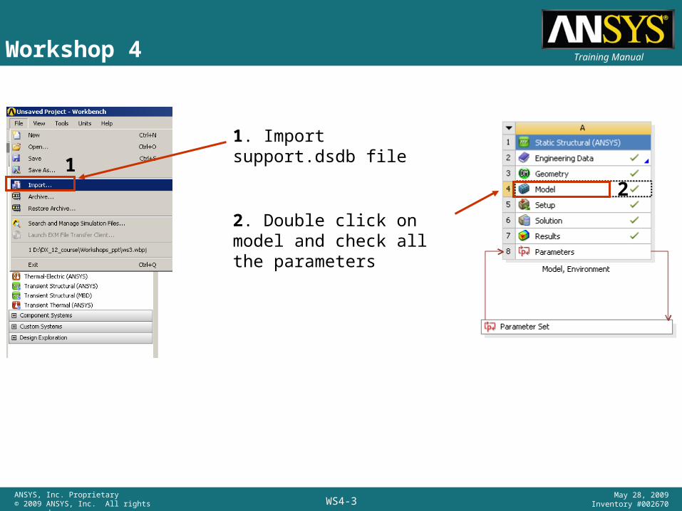
1. Import support.dsdb file
2. Double click on model and check all the parameters
12
WS4-4ANSYS, Inc. Proprietary© 2009 ANSYS, Inc. All rights reserved.
May 28, 2009Inventory #002670
Training ManualWorkshop 4
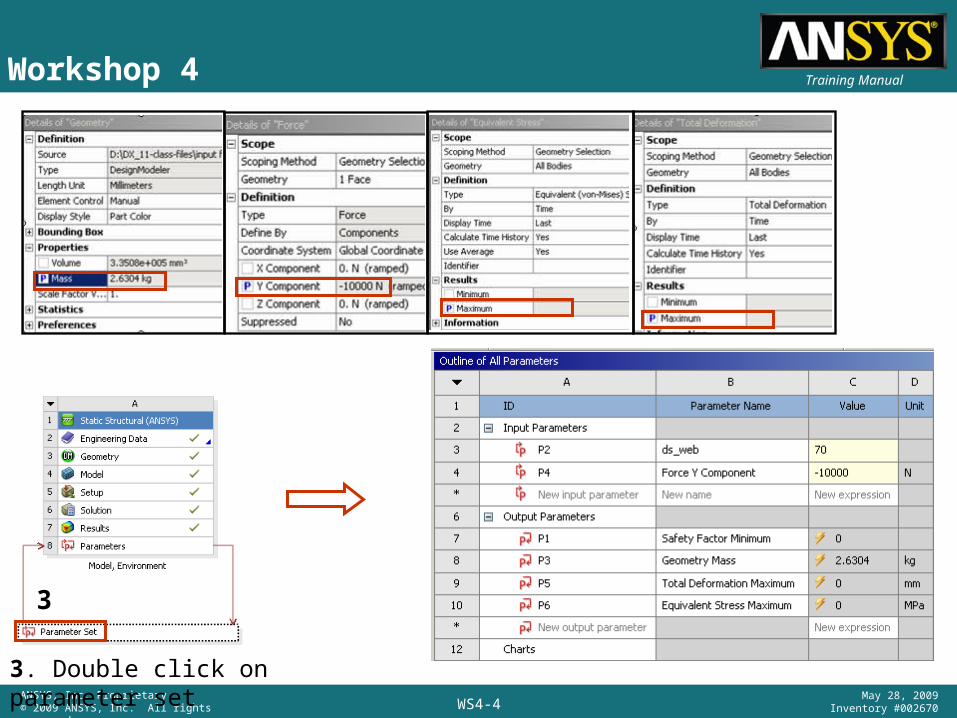
3. Double click on parameter set
3
WS4-5ANSYS, Inc. Proprietary© 2009 ANSYS, Inc. All rights reserved.
May 28, 2009Inventory #002670
Training ManualWorkshop 4
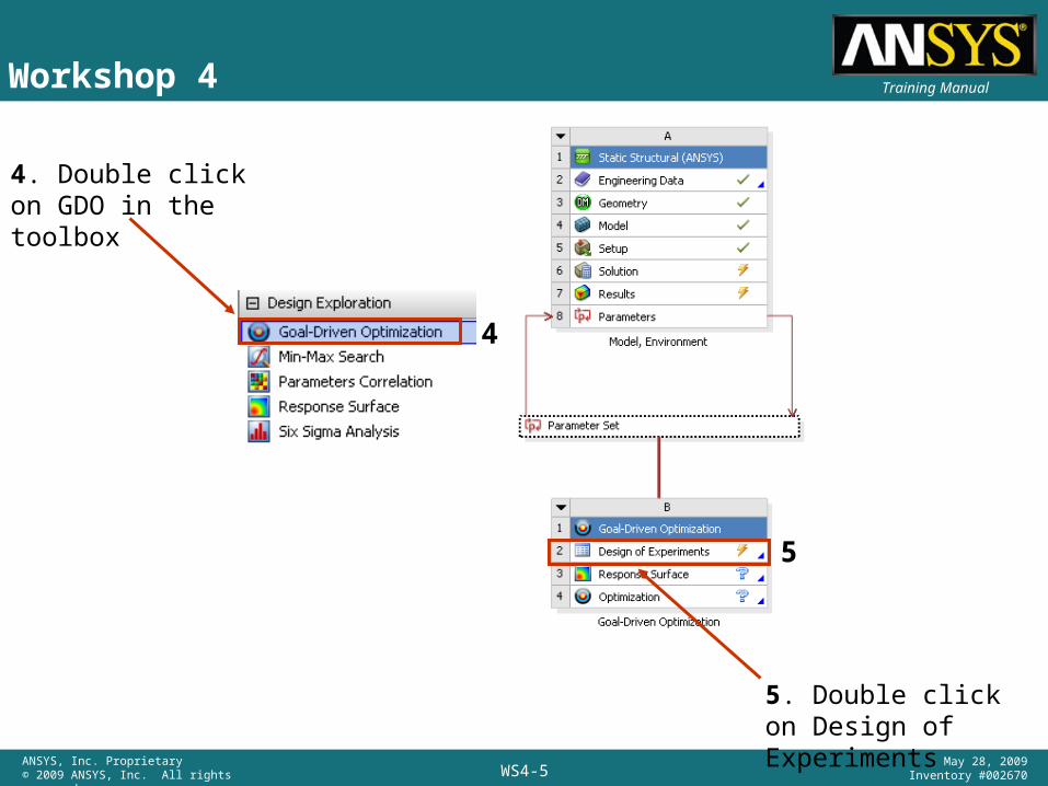
4. Double click on GDO in the toolbox
5. Double click on Design of Experiments
4
5

WS4-6ANSYS, Inc. Proprietary© 2009 ANSYS, Inc. All rights reserved.
May 28, 2009Inventory #002670
Training ManualWorkshop 4
6. Highlight parameters P2 and P4 in the outline of design of experiments, and set up lower and upper bounds as shown in the properties of outline
6 6

WS4-7ANSYS, Inc. Proprietary© 2009 ANSYS, Inc. All rights reserved.
May 28, 2009Inventory #002670
Training ManualWorkshop 4
7. Preview and Update Design of Experiments
A total of 9 automatic design points are created
7

WS4-8ANSYS, Inc. Proprietary© 2009 ANSYS, Inc. All rights reserved.
May 28, 2009Inventory #002670
Training ManualWorkshop 4
8. Double click on Design of Experiments
9. Double click on DOE
10. Change design type to Face Centered
Template type Enhanced
8
9
10
WS4-9ANSYS, Inc. Proprietary© 2009 ANSYS, Inc. All rights reserved.
May 28, 2009Inventory #002670
Training ManualWorkshop 4
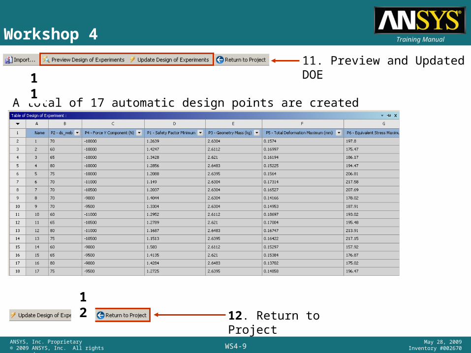
11. Preview and Updated DOE
A total of 17 automatic design points are created
12. Return to Project
11
12

WS4-10ANSYS, Inc. Proprietary© 2009 ANSYS, Inc. All rights reserved.
May 28, 2009Inventory #002670
Training ManualWorkshop 4
13. RMB on Response Surface > Update
13
WS4-11ANSYS, Inc. Proprietary© 2009 ANSYS, Inc. All rights reserved.
May 28, 2009Inventory #002670
Training ManualWorkshop 4
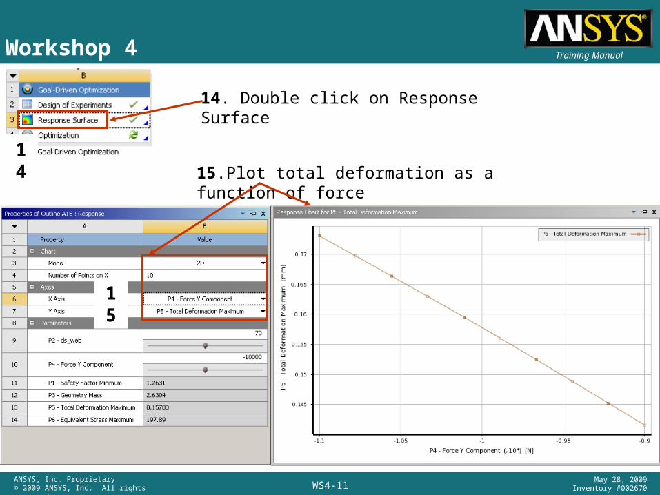
14. Double click on Response Surface
15.Plot total deformation as a function of force
15
14

WS4-12ANSYS, Inc. Proprietary© 2009 ANSYS, Inc. All rights reserved.
May 28, 2009Inventory #002670
Training ManualWorkshop 4
16. Set Mode to 3D
Check goodness of the fit for the parameter P5 – Total deformation
16

WS4-13ANSYS, Inc. Proprietary© 2009 ANSYS, Inc. All rights reserved.
May 28, 2009Inventory #002670
Training ManualWorkshop 4
17. Click on Response surface and in the Properties of Outline change from standard response surface to Kriging
18. Update response surface
17
18

WS4-14ANSYS, Inc. Proprietary© 2009 ANSYS, Inc. All rights reserved.
May 28, 2009Inventory #002670
Training ManualWorkshop 4
Plot Response surface > 3D (repeat step 16)
Plot local sensitivities and spider chart
WS4-15ANSYS, Inc. Proprietary© 2009 ANSYS, Inc. All rights reserved.
May 28, 2009Inventory #002670
Training Manual
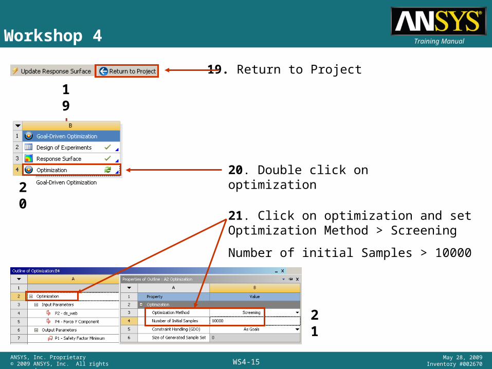
20. Double click on optimization
Workshop 4
19. Return to Project
19
20
21. Click on optimization and set Optimization Method > Screening
Number of initial Samples > 10000
21

WS4-16ANSYS, Inc. Proprietary© 2009 ANSYS, Inc. All rights reserved.
May 28, 2009Inventory #002670
Training ManualWorkshop 4
22. Set the goals as shown in optimization table
22
23. Update Optimization
23
Table of candidate designs based on the goals
WS4-17ANSYS, Inc. Proprietary© 2009 ANSYS, Inc. All rights reserved.
May 28, 2009Inventory #002670
Training ManualWorkshop 4
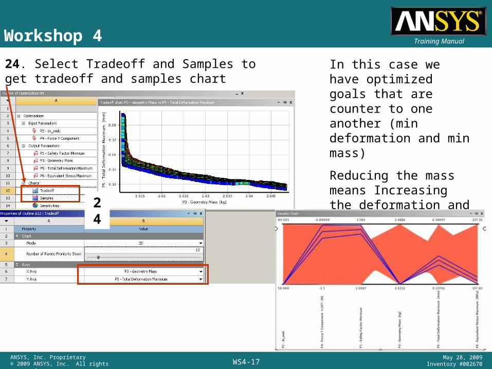
24. Select Tradeoff and Samples to get tradeoff and samples chart
In this case we have optimized goals that are counter to one another (min deformation and min mass)
Reducing the mass means Increasing the deformation and vice versa.
24

WS4-18ANSYS, Inc. Proprietary© 2009 ANSYS, Inc. All rights reserved.
May 28, 2009Inventory #002670
Training ManualWorkshop 4
25. Select candidate A, RMB, and insert it as Design Point
27. Double click on Parameter Set
25
26. Return to Project
26
27

WS4-19ANSYS, Inc. Proprietary© 2009 ANSYS, Inc. All rights reserved.
May 28, 2009Inventory #002670
Training ManualWorkshop 4
28. Update design Points
29. Select design point 1, RMB and Copy to current
30. Update Selected design point
28
29
30
31. Return to Project31

WS4-20ANSYS, Inc. Proprietary© 2009 ANSYS, Inc. All rights reserved.
May 28, 2009Inventory #002670
Training ManualMechanical slide
32. Double click on solution and check the results
32

WS4-21ANSYS, Inc. Proprietary© 2009 ANSYS, Inc. All rights reserved.
May 28, 2009Inventory #002670
Training ManualWorkshop 4
34. RMB on the Response Surface to insert the point in the response surface Response Point (see table above)
33. Double click on Response Surface
33
34

WS4-22ANSYS, Inc. Proprietary© 2009 ANSYS, Inc. All rights reserved.
May 28, 2009Inventory #002670
Training ManualWorkshop 4
35. Highlight Response Point and Insert as Design Point
36. Double click on Parameter Set
35
36

WS4-23ANSYS, Inc. Proprietary© 2009 ANSYS, Inc. All rights reserved.
May 28, 2009Inventory #002670
Training ManualWorkshop 4
37. Update Selected Design Point
38. Copy as current and update design point and you can see deformation and stress if you open Mechanical application.
37
38