Embed Size (px)
Citation preview

Printed 6:50 PM Saturday 20 March 2004
Working Draft ProjectAmerican National T10/1417-DStandard
Revision 1320 March 2004
Information technology -SCSI Block Commands - 2 (SBC-2)
This is an internal working document of T10, a Technical Committee of Accredited Standards Committee INCITS (International Committee for Information Technology Standards). As such this is not a completed standard and has not been approved. The contents may be modified by the T10 Technical Committee. The contents are actively being modified by T10. This document is made available for review and comment only.
Permission is granted to members of INCITS, its technical committees, and their associated task groups to reproduce this document for the purposes of INCITS standardization activities without further permission, provided this notice is included. All other rights are reserved. Any duplication of this document for commercial or for-profit use is strictly prohibited.
T10 Technical Editor: Robert C ElliottHewlett-Packard CorporationMC 150801PO Box 692000Houston, TX 77269-2000USA
Telephone: 281-518-5037Email: [email protected]
Reference numberISO/IEC 14776-322:200x
ANSI INCITS.***:200x

Working Draft SCSI Block Commands - 2 (SBC-2) ii
Points of Contact
International Committee for Information Technology Standards (INCITS) T10 Technical Committee
T10 Chair T10 Vice-ChairJohn B. Lohmeyer George O. PenokieLSI Logic IBM Corporation4420 Arrows West Drive MS: 2C6Colorado Springs, CO 80907-3444 3605 Highway 52 NUSA Rochester, MN 55901
USA
Telephone: (719) 533-7560 Telephone: (507) 253-5208Email: [email protected] Email: [email protected]
T10 Web Site: http://www.t10.org
T10 E-mail reflector:Server: [email protected] subscribe send e-mail with ‘subscribe’ in message bodyTo unsubscribe send e-mail with ‘unsubscribe’ in message body
INCITS SecretariatSuite 2001250 Eye Street, NWWashington, DC 20005USA
Telephone: 202-737-8888Web site: http://www.incits.orgEmail: [email protected]
Information Technology Industry CouncilWeb site: http://www.itic.org
Document DistributionINCITS Online Storemanaged by Techstreet1327 Jones DriveAnn Arbor, MI 48105USA
Web site: http://www.techstreet.com/incits.htmlTelephone: (734) 302-7801 or (800) 699-9277
Global Engineering Documents, an IHS Company15 Inverness Way EastEnglewood, CO 80112-5704USA
Web site: http://global.ihs.comTelephone: (303) 397-7956 or (303) 792-2181 or (800) 854-7179

20 March 2004 T10/1417-D Revision 13
Working Draft SCSI Block Commands - 2 (SBC-2) iii
American National Standardfor Information Technology
SCSI Block Commands - 2 (SBC-2)
SecretariatInformation Technology Industry Council
Approved mm.dd.yy
American National Standards Institute, Inc.
ABSTRACTThis standard specifies the functional requirements for the SCSI Block Commands - 2 (SBC-2) command set. SBC-2 permits SCSI block logical units such as rigid disks to attach to computers and provides the definition for their use.
This standard maintains a high degree of compatibility with the SCSI Block Commands (SBC) command set, NCITS.306:1998, and while providing additional functions, is not intended to require changes to presently installed devices or existing software.

T10/1417-D Revision 13 20 March 2004
iv Working Draft SCSI Block Commands - 2 (SBC-2)
Published byAmerican National Standards Institute11 W. 42nd Street, New York, New York 10036Copyright © 2003 by Information Technology Industry Council (ITI).All rights reserved.
No part of this publication may by reproduced in anyform, in an electronic retrieval system or otherwise,without prior written permission of ITI, 1250 Eye Street NW, Suite 200,Washington, DC 20005.
Printed in the United States of America
American National Standard
Approval of an American National Standard requires verification by ANSI that the requirements for due process, consensus, and other criteria for approval have been met by the standards developer. Consensus is established when, in the judgment of the ANSI Board of Standards Review, substantial agreement has been reached by directly and materially affected interests. Substantial agreement means much more than a simple majority, but not necessarily unanimity. Consensus requires that all views and objections be considered, and that effort be made towards their resolution.
The use of American National Standards is completely voluntary; their existence does not in any respect preclude anyone, whether he has approved the standards or not, from manufacturing, marketing, purchasing, or using products, processes, or procedures not conforming to the standards.
The American National Standards Institute does not develop standards and will in no circumstances give interpretation on any American National Standard. Moreover, no person shall have the right or authority to issue an interpretation of an American National Standard in the name of the American National Standards Institute. Requests for interpretations should be addressed to the secretariat or sponsor whose name appears on the title page of this standard.
CAUTION NOTICE: This American National Standard may be revised or withdrawn at any time. The procedures of the American National Standards Institute require that action be taken periodically to reaffirm, revise, or withdraw this standard. Purchasers of American National Standards may receive current information on all standards by calling or writing the American National Standards Institute.
CAUTION: The developers of this standard have requested that holders of patents that may be required for the implementation of the standard, disclose such patents to the publisher. However, neither the developers nor the publisher have undertaken a patent search in order to identify which, if any, patents may apply to this standard. As of the date of publication of this standard, following calls for the identification of patents that may be required for the implementation of the standard, no such claims have been made. No further patent search is conducted by the developer or the publisher in respect to any standard it processes. No representation is made or implied that licenses are not required to avoid infringement in the use of this standard.

20 March 2004 T10/1417-D Revision 13
Working Draft SCSI Block Commands - 2 (SBC-2) v
DedicationThis standard is dedicated to the memory of Gene E. Milligan, who was the original editor.
Mr. Milligan was a dedicated and energetic participant on several NCITS Technical Committees, including T10, T11, T12, and T13. He chaired both T12 and T13 and was the International Representative for T10, T11, and T12.
Mr. Milligan graduated in 1959 from UCLA with a degree in Electrical Engineering and was employed by Seagate Technology for over 30 years. His interests included flying, water and snow skiing, and tinkering with anything that needed repair. He was also an avid sports fan.
Memorial gifts may be made to Habitat for Humanity.

T10/1417-D Revision 13 20 March 2004
vi Working Draft SCSI Block Commands - 2 (SBC-2)
Revision Information
R.1 Revision 0 (5 July 2000)a) Converted to ISO/IEC style.b) Incorporated the following proposals:
A) 98-202r1 - Obsolete Extent ReservationsB) 98-202r1 - Obsolete Change DefinitionC) 98-203r9 - Persistent Reservation ChangesD) 99-189r0 - ECC correction span spec for 255E) 99-259r4 - 2 Terabyte Changes. Note that the proposal had *, **, or *** on several commands but
no explanation of the *, **, or ***.F) 00-125r0 - Large LBA address using variable length CDB structure
R.2 Revision 1 (27 August 2000)a) Incorporated the following proposal:
A) 99-258r2 - List lengths that exceed the maximum with wording changes approved at the 7/2000 meeting.
b) Added note after reservation conflict tables per prior editor’s note and 7/2000 meeting.c) Added “may not” to key words per 7/2000 meeting.
R.3 Revision 2 (4 October 2000)a) Added missing operation code for XDREADb) Incorporated the following proposals:
A) 00-248r2 - SBC-2 issues - Item 6 - Initialization Pattern using the least significant 4 bytes of the LBA
B) 00-333r0 - SCSI is a functional standardC) 00-248r2 - SBC-2 issues - Editorial changes
R.4 Revision 3 (17 May 2001)a) Added GEM dedication page.b) Corrected spelling, cross reference, and formatting errors throughout the document.c) Deleted about 12,000 extraneous spaces.d) Reformatted tables to follow SPI-4 style.e) Generated PDF with bookmarks enabled.f) Changed Times-Roman font to Arial in the few places it was used.g) Made small-caps use more consistent.h) Updated front material based on SPI-3 revision 14.i) Added hierarchy to annexes.j) Fixed sense key/additional sense code mixup in Logical blocks section 4.2.1.3.k) Fixed VERIFY (16) and WRITE SAME (16) (they only had 10 CDB bytes).l) Moved all READ, VERIFY, WRITE, WRITE AND VERIFY commands into section 5.1. Added text
explaining that the BLKVFY or EBP bits are considered reserved for direct-access devices. This addresses Gene’s editorial note 1 asking whether optical VERIFY (16) and WRITE AND VERIFY (16) should point to optical-memory or direct-access versions of the CDBs.
m) Added notes in WRITE (6) and WRITE (10) about their different handling of transfer length of 0.n) Added READ (16) and LOCK UNLOCK CACHE (16) to list of supported commands for optical and
write-once devices, since the write commands were already added. The preface to 99-259r4 only requested new large LBA commands for direct-access devices, but provided reservation tables for all 3 types. SBC-2 revision 2 included most of them; it seems appropriate to allow the rest as well.
o) Changed PRE-FETCH to PRE-FETCH (10) since there is now a PRE-FETCH (16) too.p) Merged all the reservation tables into one to avoid duplication of most of the rows (and potential
conflicts).q) Reconciled with SPC-2 revision 19:
A) In variable length CDBs, changed ENCRYPTION IDENTIFICATION to Reserved to match SPC-2 revision 19.

20 March 2004 T10/1417-D Revision 13
Working Draft SCSI Block Commands - 2 (SBC-2) vii
B) Removed CHANGE DEFINITION, COMPARE, COPY, and COPY AND VERIFY references, since they are obsolete in SPC-2.
C) Removed the power condition mode page. SPC-2 marks page code 0Dh as obsolete, since it incorporated the entire page under code 1Ah per these proposals:
• 95-222r2 Power condition mode page code• 95-265r1 T10 plenary minutes July 1995 item 10.6 Power Condition mode page
r) Incorporated the following proposals:A) 00-315r1 - Bidirectional XDWRITEREAD command for SBC-2B) 00-395r1 - Increased defect list lengths for SBC-2C) 00-375r1 - November 2000 T10 plenary minutes - motion 10.4.4: “READ (16) and WRITE (16)
[shall] be made mandatory for the direct-access device type”. Noted that WRITE (16) is only mandatory if any WRITE command is implemented.
R.5 Revision 4 (28 July 2001)a) Obsoleted 0Dh and moved Power Condition mode page to 1Ah in optical drives table 122.b) Corrected opcodes in READ (16) and WRITE SAME (16)c) Incorporated the following proposals:
A) 00-425r4 Long Identifiers in SPC-3, SAM-2, SBC-2 and other XOR issuesB) 01-134r2 WAKEUP and RESET cleanupC) 01-210r0 Reassign Blocks 2 TB support
R.6 Revision 5 (23 February 2002)a) 01-246 Long LBA PMI support for Read Capacityb) 01-199 Sense Data INFORMATION field for long LBAs and bidirectional commandsc) New text about security initialize for FORMAT UNIT per email from Eugene Zilberman of M-Systems
R.7 Revision 5a (2 March 2002)a) made mode page, log page, and diagnostic page references use consistent naming convention and
capitalizationb) upgraded references to other standardsc) definition and keyword sections reformattedd) keywords and conventions section rewrittene) updated log page and mode page list to match SPC-3f) no change bars
R.8 Revision 6 (1 May 2002)a) fixed hanging paragraphs in 5.1 and some table formatsb) 02-130r0 SBC-2, SSC-2, SMC-2 & OSD Support for All Registrants Persistent Reservationsc) Updated supported commands tables to match SPC-3 revision 6 opcode table. Added SCC-2
commands to each device type; corrected SMC-2 command names; added new SPC-2/SPC-3 commands to each device type; included obsolete command names in notes.
R.9 Revision 7 (28 June 2002)a) changed footnotes to use superscript lettersb) 02-277r1 obsolete RESERVE and RELEASE (Dave Peterson)[02-273 7/2002 T10 Plenary]c) 02-260r1 Mandatory REPORT LUNS support (Dave Peterson)[02-273 7/2002 T10 Plenary]
R.10 Revision 8 (30 September 2002)Incorporated the following proposals:
a) removed LONGLBA bit from READ CAPACITY (10) tableb) 02-232r2 Clearing effects of I_T nexus loss (Rob Elliott) [02-344 9/2002 T10 Plenary]c) Added table summarizing SERVICE ACTION IN service actions (READ CAPACITY (16).

T10/1417-D Revision 13 20 March 2004
viii Working Draft SCSI Block Commands - 2 (SBC-2)
d) Corrected Type column entries in FORMAT UNIT defect descriptor formats table from 000b to O (optional) to match SCSI-2.
e) Per 02-346r1 and spc3r09, added REPORT SUPPORTED TASK MANAGEMENT FUNCTIONS as an optional command
f) Per 02-189r1 and spc3r09, expanded range of diagnostic page codes for SES to 00-1Fh from 00-0Fh.
R.11 Revision 9 (31 May 2003)Incorporated the following changes:
a) miscellaneous editorial corrections from George Penokie (IBM) and Jim Hafner (IBM)b) converted from Microsoft Word into Adobe FrameMaker. Redrew all figures in Microsoft Visio.c) 02-464r3 SAM-3 SPC-3 SBC-2 Power conditions updates (Mark Evans) [03-179 5/2003 T10 Plenary]d) 03-028r1 SBC-2 Block Limits mode page [03-048 1/2003 T10 Plenary]e) Marked certain fields “restricted for MMC-4” in WRITE (10), VERIFY (10), and the Read-Write Error
Recovery mode page (byte 7 bits 1:0) based on MMC-4 revision 2. MMC-4 adds some streaming bits in those locations in its versions of those commands. They might be useful for disk drives in the future.
R.12 Revision 10 (13 September 2003)Incorporated the following changes:
a) Corrected header levels for power conditions model sectionb) 03-243r2 Optional INQUIRY processing before entering task set (George Penokie, IBM)c) Correct byte numbers in REBUILD (32), XDWRITE EXTENDED (64), and XPWRITE (32)
R.13 Revision 11 (8 December 2003)Incorporated the following changes per the November CAP WG (03-370), November T10 plenary (03-372), and November editor’s meeting:
a) 03-335r1 SBC-2 SPC-3 Obsolete block device linked commands (Rob Elliott, HP)b) 03-365r1 End-to-end data protection (George Penokie, IBM) (really r11 of 03-176)c) 03-362r0 SBC-2 Obsolete SEEK (10) (Rob Elliott, HP)d) 03-383r1 SBC-2 new READ LONG (16) and WRITE LONG (16) commands (Mark Evans, Maxtor)e) Miscellaneous changes from November editors meetingf) Changed “block size” to “block length”g) Changed “data block” and “block” to “logical block” or “physical block” as appropriate. Mention that
logical block consists of both user data and protection information many places.h) Changed “direct access” to “direct-access”, “write once” to “write-once”, and “optical memory” to
“optical-memory”i) Changed “direct-access block device” to “direct-access device”, “write-once block device” to
“write-once device”, and “optical-memory block device” to “optical-memory device”j) Added some definitions from SSC-2 (e.g. application client, additional sense code, byte, ...)k) Changed “logical block address” to “LBA” except where used as a field namel) Changed “command descriptor block” to “CDB”m) Changed “sense data to ILLEGAL REQUEST” constructs to “sense key to ILLEGAL REQUEST”n) Restructured the FORMAT UNIT defect descriptor format and requirements tableo) Made the defect descriptor names consistent: short block, long block, bytes from index, physical
sectorp) Mention all the commands that use defect descriptors in the defect descriptor definitionq) Changed block size to block lengthr) Changed some specfies/indicates usage to follow T10 standard (application client specifies, device
server indicates)s) Cleaned up footer in optical-memory density codes table

20 March 2004 T10/1417-D Revision 13
Working Draft SCSI Block Commands - 2 (SBC-2) ix
R.14 Revision 12 (25 January 2004)Incorporated the following changes per the January CAP WG (04-038r0) and plenary (04-039r0):
a) 03-387r2 SBC-2 Data protection usage detection (Rob Elliott, HP)b) 04-016r2 SBC-2 SPC-3 Obsolete Third Party XOR Commands (Jim Coomes, Seagate)c) 04-013r1 SBC-2 List of functions to obsolete (George Penokie, IBM). Obsoleted all the functional
fields in the Device Input Status diagnostic page (synchronization, rotational position locking, etc.), just leaving the vendor-specific fields. Deleted the direct-access medium type codes table (for the mode parameter header), just requiring the medium type field be set to 00h.
d) 04-024r1 SBC-2 Data protection information for XPWRITE (Jim Coomes, Seagate)e) 04-025r0 SPC-3 and SBC-2 power conditions clarifications (Mark Evans, Maxtor)f) Changed PLIST, GLIST, DLIST, and CLIST acronyms from small caps to all caps. Renamed PLIST and
GLIST fields in READ DEFECT DATA CDBs to REQ_PLIST and REQ_LIST. Renamed PLIST and GLIST fields in the read defect data to PLISTV and GLISTV.
g) Made specifies/indicates usage consistent throughout chapter 5.h) Lots of changes from the January editor’s meeting.
R.15 Revision 13 (20 March 2004)Incorporated the following changes per the March CAP WG (04-084r0) and plenary (04-085r0):
a) 04-012r1 SBC-2 WRITE SAME corrections (George Penokie, IBM)b) 03-348r2 SBC-2 4-byte LBA commands on 8-byte LBA capable drives (Rob Elliott, HP)a) 04-076r0 SBC-2 PRE-FETCH and errors (Rob Elliott, HP)b) Changed block defect descriptor paragraphs which were made more broken, not less, in revision 12
(please review)c) Miscellaneous editorial changes
R.16 Pending proposalsThe following proposals are pending:
a) Monitor MMC-4 for additional bits (Keiji Katata (Pioneer) will provide notice) to mark as restricted.b) 03-307 SBC-2 32-byte commands for end-to-end data protection (Jim Coomes, Seagate)c) 03-336 End-to-end data protection information field ordering (Keith Holt, LSI Logic)d) 03-361 Command classification field (George Penokie, IBM)e) 03-388 SBC-2 Nonvolatile caches (Rob Elliott, HP)f) 04-011 SBC-2 Changing logical block sizes (George Penokie, IBM)g) 04-031 SPC-3 SES-2 SBC-2 Miscellaneous diagnostic page topics (04-031) (Rob Elliott, HP)h) 04-075 SBC-2 Obsolete more features (Rob Elliott, HP)i) 04-082 SBC-2 Replace Notch and Partition mode page with READ CAPACITY (Rob Elliott, HP)

T10/1417-D Revision 13 20 March 2004
x Working Draft SCSI Block Commands - 2 (SBC-2)
ContentsPage
1 Scope ............................................................................................................................................................. 1
2 Normative References ................................................................................................................................... 32.1 Normative references overview ................................................................................................................ 32.2 Approved references ................................................................................................................................ 32.3 References under development ............................................................................................................... 4
3 Definitions, symbols, abbreviations, keywords, and conventions .................................................................. 53.1 Definitions................................................................................................................................................. 53.2 Symbols and abbreviations ...................................................................................................................... 73.3 Keywords.................................................................................................................................................. 73.4 Conventions.............................................................................................................................................. 8
4 Models.......................................................................................................................................................... 104.1 General................................................................................................................................................... 104.2 Direct-access device type model overview............................................................................................. 104.3 Removable medium................................................................................................................................ 10
4.3.1 Removable medium overview........................................................................................................... 104.3.2 Removable medium with an attached medium changer ................................................................... 11
4.4 Logical blocks ......................................................................................................................................... 114.5 Ready state ............................................................................................................................................ 124.6 Initialization............................................................................................................................................. 124.7 Implicit HEAD OF QUEUE command processing .................................................................................. 124.8 Medium defects ...................................................................................................................................... 124.9 Cache memory ....................................................................................................................................... 134.10 Reservations......................................................................................................................................... 144.11 Notched devices ................................................................................................................................... 154.12 Error reporting ...................................................................................................................................... 154.13 Examples.............................................................................................................................................. 17
4.13.1 Examples overview ......................................................................................................................... 174.13.2 Rotating media................................................................................................................................ 174.13.3 Memory media ................................................................................................................................ 17
4.14 Model for XOR commands ................................................................................................................... 184.14.1 Model for XOR commands overview .............................................................................................. 18
4.14.1.1 Storage array controller supervised XOR operations................................................................ 184.14.1.1.1 Storage array controller supervised XOR operations overview ........................................... 184.14.1.1.2 Update write operation (storage array controller supervised) .............................................. 184.14.1.1.3 Regenerate operation (storage array controller supervised) ............................................... 194.14.1.1.4 Rebuild operation (storage array controller supervised)...................................................... 19
4.14.1.2 Additional array subsystem considerations ............................................................................... 194.14.1.2.1 Additional array subsystem considerations overview .......................................................... 194.14.1.2.2 Buffer full status handling .................................................................................................... 194.14.1.2.3 Access to an inconsistent stripe .......................................................................................... 20
4.14.1.3 Error handling considerations.................................................................................................... 204.14.1.3.1 Error handling considerations overview............................................................................... 204.14.1.3.2 Primary errors - errors resulting directly from the primary command .................................. 20
4.14.1.4 XOR data retention requirements.............................................................................................. 204.14.2 START STOP UNIT and power conditions ..................................................................................... 21
4.14.2.1 START STOP UNIT and power conditions overview ................................................................ 214.14.2.2 START STOP UNIT and power conditions state machine ........................................................ 21
4.14.2.2.1 START STOP UNIT and power conditions state machine overview ................................... 214.14.2.2.2 SSU_PC0:Powered_on state .............................................................................................. 22
4.14.2.2.2.1 SSU_PC0:Powered_on state description ..................................................................... 224.14.2.2.2.2 Transition SSU_PC0:Powered_on to SSU_PC1:Active................................................ 22
20 March 2004 T10/1417-D Revision 13
Working Draft SCSI Block Commands - 2 (SBC-2) xi
4.14.2.2.2.3 Transition SSU_PC0:Powered_on to SSU_PC4:Stopped ............................................ 224.14.2.2.3 SSU_PC1:Active state......................................................................................................... 23
4.14.2.2.3.1 SSU_PC1:Active state description................................................................................ 234.14.2.2.3.2 Transition SSU_PC1:Active to SSU_PC2:Idle .............................................................. 234.14.2.2.3.3 Transition SSU_PC1:Active to SSU_PC3:Standby....................................................... 234.14.2.2.3.4 Transition SSU_PC1:Active to SSU_PC4:Stopped ...................................................... 23
4.14.2.2.4 SSU_PC2:Idle state............................................................................................................. 234.14.2.2.4.1 SSU_PC2:Idle state description.................................................................................... 234.14.2.2.4.2 Transition SSU_PC2:Idle to SSU_PC1:Active .............................................................. 234.14.2.2.4.3 Transition SSU_PC2:Idle to SSU_PC3:Standby........................................................... 244.14.2.2.4.4 Transition SSU_PC2:Idle to SSU_PC4:Stopped .......................................................... 24
4.14.2.2.5 SSU_PC3:Standby state ..................................................................................................... 244.14.2.2.5.1 SSU_PC3:Standby state description ............................................................................ 244.14.2.2.5.2 Transition SSU_PC3:Standby to SSU_PC1:Active....................................................... 244.14.2.2.5.3 Transition SSU_PC3:Standby to SSU_PC2:Idle........................................................... 244.14.2.2.5.4 Transition SSU_PC3:Standby to SSU_PC4:Stopped ................................................... 24
4.14.2.2.6 SSU_PC4:Stopped state ..................................................................................................... 244.14.2.2.6.1 SSU_PC4:Stopped state description ............................................................................ 244.14.2.2.6.2 Transition SSU_PC4:Stopped to SSU_PC1:Active ...................................................... 254.14.2.2.6.3 Transition SSU_PC4:Stopped to SSU_PC2:Idle .......................................................... 254.14.2.2.6.4 Transition SSU_PC4:Stopped to SSU_PC3:Standby ................................................... 25
4.15 Protection information model................................................................................................................ 254.15.1 Protection information overview...................................................................................................... 254.15.2 Protection information format.......................................................................................................... 264.15.3 Logical block guard ......................................................................................................................... 26
4.15.3.1 Logical block guard overview .................................................................................................... 264.15.3.2 CRC generation......................................................................................................................... 274.15.3.3 CRC checking ........................................................................................................................... 284.15.3.4 CRC test cases ......................................................................................................................... 29
4.15.4 Application of protected data .......................................................................................................... 294.15.5 Protected data commands .............................................................................................................. 29
5 Commands for direct-access block devices................................................................................................. 305.1 Opcodes for variable length CDB opcodes ............................................................................................ 305.2 Commands for direct-access devices overview ..................................................................................... 315.3 FORMAT UNIT command ...................................................................................................................... 34
5.3.1 FORMAT UNIT command overview ................................................................................................. 345.3.2 Defect list header .............................................................................................................................. 395.3.3 Defect list formats ............................................................................................................................. 41
5.3.3.1 Defect list formats overview ........................................................................................................ 415.3.3.2 Short block format defect descriptor............................................................................................ 415.3.3.3 Long block format defect descriptor ............................................................................................ 425.3.3.4 Bytes from index format defect descriptor................................................................................... 425.3.3.5 Physical sector format defect descriptor ..................................................................................... 43
5.3.4 Initialization pattern ........................................................................................................................... 435.4 LOCK UNLOCK CACHE (10) command ................................................................................................ 455.5 LOCK UNLOCK CACHE (16) command ................................................................................................ 465.6 PRE-FETCH (10) command................................................................................................................... 465.7 PRE-FETCH (16) command................................................................................................................... 475.8 READ (6) command ............................................................................................................................... 485.9 READ (10) command ............................................................................................................................. 495.10 READ (12) command ........................................................................................................................... 545.11 READ (16) command ........................................................................................................................... 545.12 READ CAPACITY (10) command ........................................................................................................ 545.13 READ CAPACITY (16) command ........................................................................................................ 565.14 READ DEFECT DATA (10) command ................................................................................................. 575.15 READ DEFECT DATA (12) command ................................................................................................. 59

T10/1417-D Revision 13 20 March 2004
xii Working Draft SCSI Block Commands - 2 (SBC-2)
5.16 READ LONG (10) command ................................................................................................................ 605.17 READ LONG (16) command ................................................................................................................ 615.18 REASSIGN BLOCKS command........................................................................................................... 615.19 START STOP UNIT command............................................................................................................. 635.20 SYNCHRONIZE CACHE (10) command.............................................................................................. 655.21 SYNCHRONIZE CACHE (16) command.............................................................................................. 665.22 VERIFY (10) command ........................................................................................................................ 665.23 VERIFY (12) command ........................................................................................................................ 755.24 VERIFY (16) command ........................................................................................................................ 755.25 WRITE (6) command............................................................................................................................ 765.26 WRITE (10) command.......................................................................................................................... 775.27 WRITE (12) command.......................................................................................................................... 805.28 WRITE (16) command.......................................................................................................................... 805.29 WRITE AND VERIFY (10) command ................................................................................................... 805.30 WRITE AND VERIFY (12) command ................................................................................................... 815.31 WRITE AND VERIFY (16) command ................................................................................................... 825.32 WRITE LONG (10) command............................................................................................................... 825.33 WRITE LONG (16) command............................................................................................................... 835.34 WRITE SAME (10) command............................................................................................................... 835.35 WRITE SAME (16) command............................................................................................................... 855.36 XDREAD (10) command ...................................................................................................................... 865.37 XDREAD (32) command ...................................................................................................................... 875.38 XDWRITE (10) command..................................................................................................................... 875.39 XDWRITE (32) command..................................................................................................................... 885.40 XDWRITEREAD (10) command........................................................................................................... 895.41 XDWRITEREAD (32) command........................................................................................................... 895.42 XPWRITE (10) command ..................................................................................................................... 905.43 XPWRITE (32) command ..................................................................................................................... 91
6 Parameters for direct-access block devices................................................................................................. 936.1 Diagnostic parameters............................................................................................................................ 93
6.1.1 Diagnostic parameters overview....................................................................................................... 936.1.2 Translate Address Output diagnostic page....................................................................................... 936.1.3 Translate Address Input diagnostic page.......................................................................................... 946.1.4 Device Status Output diagnostic page.............................................................................................. 956.1.5 Device Status Input diagnostic page................................................................................................. 96
6.2 Log parameters ...................................................................................................................................... 976.2.1 Log parameters overview.................................................................................................................. 976.2.2 Format Status log page..................................................................................................................... 97
6.3 Mode parameters ................................................................................................................................... 996.3.1 Mode parameters overview............................................................................................................... 996.3.2 Caching mode page........................................................................................................................ 1016.3.3 Notch And Partition mode page ...................................................................................................... 1046.3.4 Read-Write Error Recovery mode page.......................................................................................... 1056.3.5 Verify Error Recovery mode page................................................................................................... 1106.3.6 XOR Control mode page................................................................................................................. 111
6.4 Vital product data (VPD) parameters.................................................................................................... 1116.4.1 VPD parameters overview .............................................................................................................. 1116.4.2 Block Limits VPD page ................................................................................................................... 112
Annex A XOR command examples............................................................................................................... 113A.1 XOR command examples overview ..................................................................................................... 113A.2 Update write operation ......................................................................................................................... 113A.3 Regenerate operation .......................................................................................................................... 114A.4 Rebuild operation ................................................................................................................................. 115

20 March 2004 T10/1417-D Revision 13
Working Draft SCSI Block Commands - 2 (SBC-2) xiii
TablesPage
1 Standards bodies .......................................................................................................................................... 32 ISO and American numbering conventions ................................................................................................... 93 SBC-2 commands that are allowed in the presence of various reservations .............................................. 144 Example error conditions ............................................................................................................................ 165 Sense data field usage for direct-access devices ....................................................................................... 166 User data and protection information format ............................................................................................... 267 CRC polynomials ........................................................................................................................................ 278 Variable length command service action code assignments ...................................................................... 309 SERVICE ACTION IN service actions ........................................................................................................ 3010 SERVICE ACTION OUT service actions .................................................................................................. 3111 Commands for direct-access devices ....................................................................................................... 3112 FORMAT UNIT command ......................................................................................................................... 3513 FORMAT UNIT parameter list ................................................................................................................... 3614 FORMAT UNIT defect descriptor format and requirements ...................................................................... 3815 Short defect list header ............................................................................................................................. 3916 Long defect list header .............................................................................................................................. 3917 Defect descriptor formats .......................................................................................................................... 4118 Short block format defect descriptor (000b) .............................................................................................. 4119 Long block format defect descriptor (011b) ............................................................................................... 4220 Bytes from index format defect descriptor (100b) ..................................................................................... 4221 Physical sector format defect descriptor (101b) ........................................................................................ 4322 Initialization pattern descriptor .................................................................................................................. 4323 Initialization pattern modifier ..................................................................................................................... 4424 Initialization pattern type ........................................................................................................................... 4425 LOCK UNLOCK CACHE (10) command ................................................................................................... 4526 LOCK UNLOCK CACHE (16) command ................................................................................................... 4627 PRE-FETCH (10) command ..................................................................................................................... 4628 PRE-FETCH (16) command ..................................................................................................................... 4729 READ (6) command .................................................................................................................................. 4830 Protection information checking for READ (6) .......................................................................................... 4931 READ (10) command ................................................................................................................................ 4932 RDPROTECT field ......................................................................................................................................... 5033 READ (12) command ................................................................................................................................ 5434 READ (16) command ................................................................................................................................ 5435 READ CAPACITY (10) command ............................................................................................................. 5536 Short read capacity data ........................................................................................................................... 5537 READ CAPACITY (16) command ............................................................................................................. 5638 Long read capacity data ............................................................................................................................ 5639 READ DEFECT DATA (10) command ...................................................................................................... 5740 READ DEFECT DATA (10) defect list ....................................................................................................... 5841 READ DEFECT DATA (12) command ...................................................................................................... 5942 READ DEFECT DATA (12) defect list ....................................................................................................... 5943 READ LONG (10) command ..................................................................................................................... 6044 READ LONG (16) command ..................................................................................................................... 6145 REASSIGN BLOCKS command ............................................................................................................... 6246 REASSIGN BLOCKS defect list ................................................................................................................ 6247 REASSIGN BLOCKS short defect header ................................................................................................ 6248 REASSIGN BLOCKS long defect header ................................................................................................. 6349 START STOP UNIT command ................................................................................................................. 6450 POWER CONDITIONS field ............................................................................................................................. 6451 SYNCHRONIZE CACHE (10) command .................................................................................................. 6552 SYNCHRONIZE CACHE (16) command .................................................................................................. 6653 VERIFY (10) command ............................................................................................................................. 6654 VRPROTECT field with BYTCHK set to zero - checking protection information read from the medium .......... 68

T10/1417-D Revision 13 20 March 2004
xiv Working Draft SCSI Block Commands - 2 (SBC-2)
55 VRPROTECT field with BYTCHK set to one - checking protection information read from the medium ........... 7056 VRPROTECT field with BYTCHK set to one - checking protection information from the application client ..... 7257 VRPROTECT field with BYTCHK set to one - byte-by-byte comparison requirements ................................... 7358 VERIFY (12) command ............................................................................................................................. 7559 VERIFY (16) command ............................................................................................................................. 7560 WRITE (6) command ................................................................................................................................ 7661 WRITE (10) command .............................................................................................................................. 7762 WRPROTECT field ........................................................................................................................................ 7863 WRITE (12) command .............................................................................................................................. 8064 WRITE (16) command .............................................................................................................................. 8065 WRITE AND VERIFY (10) command ........................................................................................................ 8166 WRITE AND VERIFY (12) command ........................................................................................................ 8167 WRITE AND VERIFY (16) command ........................................................................................................ 8268 WRITE LONG (10) command ................................................................................................................... 8269 WRITE LONG (16) command ................................................................................................................... 8370 WRITE SAME (10) command ................................................................................................................... 8471 LBDATA bit and PBDATA bit ......................................................................................................................... 8572 WRITE SAME (16) command ................................................................................................................... 8573 XDREAD (10) command ........................................................................................................................... 8674 XDREAD (32) command ........................................................................................................................... 8775 XDWRITE (10) command ......................................................................................................................... 8776 XDWRITE (32) command ......................................................................................................................... 8877 XDWRITEREAD (10) command ............................................................................................................... 8978 XDWRITEREAD (32) command ............................................................................................................... 9079 XPWRITE (10) command .......................................................................................................................... 9080 XPWRITE (32) command .......................................................................................................................... 9281 Diagnostic page codes .............................................................................................................................. 9382 Translate Address Output diagnostic page ............................................................................................... 9383 Translate Address Input diagnostic page .................................................................................................. 9484 Device Status Output diagnostic page ...................................................................................................... 9585 Device Status Input diagnostic page ......................................................................................................... 9686 Log page codes ......................................................................................................................................... 9787 Format Status log page parameter codes ................................................................................................. 9888 DEVICE-SPECIFIC PARAMETER field .............................................................................................................. 9989 Mode page codes for direct-access devices ........................................................................................... 10090 Caching mode page ................................................................................................................................ 10191 Demand read retention priority and write retention priority ..................................................................... 10292 Notch And Partition mode page .............................................................................................................. 10493 Read-Write Error Recovery mode page .................................................................................................. 10594 Error recovery bit definitions ................................................................................................................... 10795 Combined error recovery parameter descriptions ................................................................................... 10896 Verify Error Recovery mode page ........................................................................................................... 11097 XOR Control mode page ......................................................................................................................... 11198 Direct-access device VPD page codes ................................................................................................... 11199 Block Limits VPD page ............................................................................................................................ 112

20 March 2004 T10/1417-D Revision 13
Working Draft SCSI Block Commands - 2 (SBC-2) xv
FiguresPage
1 SCSI document relationships ........................................................................................................................ 12 Power condition state machine for logical units implementing the START STOP UNIT command ............ 223 Even byte CRC generator bit order ............................................................................................................. 28A.1 Update write operation (storage array controller supervised) ................................................................ 114A.2 Regenerate operation (storage array controller supervised) ................................................................. 115A.3 Rebuild operation (storage array controller supervised) ........................................................................ 116

T10/1417-D Revision 13 20 March 2004
xvi Working Draft SCSI Block Commands - 2 (SBC-2)
Foreword (This foreword is not part of this standard)Requests for interpretation, suggestions for improvement and addenda, or defect reports are welcome. They should be sent to the INCITS Secretariat, International Committee for Information Technology Standards, Information Technology Institute, 1250 Eye Street, NW, Suite 200, Washington, DC 20005-3922.
This standard was processed and approved for submittal to ANSI by the International Committee for Information Technology Standards (INCITS). Committee approval of the standard does not necessarily imply that all committee members voted for approval. At the time it approved this standard, INCITS had the following members:
Karen Higginbottom, Chair
David Michael, Vice-Chair

20 March 2004 T10/1417-D Revision 13
Working Draft SCSI Block Commands - 2 (SBC-2) xvii
INCITS Technical Committee T10 on Lower Level Interfaces, which developed and reviewed this standard, had the following members:
John B. Lohmeyer, Chair
George O. Penokie, Vice-Chair
Ralph O. Weber, Secretary

T10/1417-D Revision 13 20 March 2004
xviii Working Draft SCSI Block Commands - 2 (SBC-2)
IntroductionThe standard is organized as follows:
Clause 1 (Scope) describes the relationship of this standard to the SCSI family of standards.Clause 2 (Normative References) provides references to other standards and documents.Clause 3 (Definitions, symbols, abbreviations, keywords, and conventions) defines terms and
conventions used throughout this standard.Clause 4 (Models) provides an overview of the block device class and the command set.Clause 5 (Commands for direct-access block devices) describes models for the various categories of
block devices.Clause 6 (Parameters for direct-access block devices) provides the definitions of all commands unique
to block devices.
Informative Annex Annex A (XOR command examples) provides XOR command examples.

AMERICAN NATIONAL STANDARD BSR INCITS.xxx:2004
American National Standardfor Information Technology -
SCSI Block Commands - 2 (SBC-2)
Working Draft SCSI Block Commands - 2 (SBC-2) 1
1 ScopeThis standard defines the command set extensions to facilitate operation of SCSI block devices. The clauses of this standard pertaining to the SCSI block device class, implemented in conjunction with the applicable clauses of SPC-3, fully specify the standard command set for SCSI block devices.
The objective of this standard is to provide the following:
a) Permit an application client to communicate over a SCSI service delivery subsystem with a logical unit that declares itself to be a direct-access device in the PERIPHERAL DEVICE TYPE field of the standard INQUIRY data (see SPC-3);
b) Define commands unique to the type of SCSI block device;c) Define commands to manage the operation of SCSI block devices; andd) Define the differences between types of SCSI block devices.
Figure 1 shows the relationship of this standard to the other standards and related projects in the SCSI family of standards.
Figure 1 — SCSI document relationships
Figure 1 is intended to show the general relationship of the documents to one another, and is not intended to imply a relationship such as a hierarchy, protocol stack or system architecture. It indicates the applicability of a standard to the implementation of a given transport.
The set of SCSI standards specifies the interfaces, functions, and operations necessary to ensure interoperability between conforming SCSI implementations. This standard is a functional description. Conforming implementations may employ any design technique that does not violate interoperability.
This standard makes obsolete the following concepts from previous standards:
a) relative addressing (including the RELADR bit in many CDBs) and the SET LIMITS commands;b) the CHANGE DEFINITION, COMPARE, COPY, COPY AND VERIFY, RESERVE, RELEASE,
REZERO UNIT, SEEK, SEARCH DATA HIGH, SEARCH DATA EQUAL, and SEARCH DATA LOW commands;
c) third-party and hybrid XOR commands (REBUILD, REGENERATE, and XDWRITE EXTENDED);d) the optical-memory device type, model, commands (ERASE, MEDIUM SCAN, READ GENER-
ATION, READ UPDATED BLOCK, and UPDATE BLOCK), and parameters (Optical-Memory mode page);
e) the erase by-pass (EBP) bit in the WRITE and WRITE AND VERIFY commands (this bit was formerly reserved for direct-access device types, so is just marked reserved in this standard);
f) the write-once device type, model, commands, and parameters;
Device-type specificcommand sets (e.g., SBC-2,
SSC-2, this standard)
Primary command set(shared for all device types)
(SPC-3)
Protocols (e.g., FCP-2, SAS SSP)
Interconnects (e.g., Fibre Channel, SAS)
SC
SI A
rchi
tect
ure
Mod
el(S
AM
-2)
T10/1417-D Revision 13 20 March 2004
2 Working Draft SCSI Block Commands - 2 (SBC-2)
g) the Flexible Disk mode page;h) the Format Device mode page;i) the Medium Types Supported mode page and all medium types in the mode parameter headerj) the Rigid Disk Geometry mode page;k) these Read-Write Errory Recovery mode page fields: CORRECTION SPAN, HEAD OFFSET COUNT, and
DATA STROBE OFFSET COUNT;l) this Verify Error Recovery mode page field: VERIFY CORRECTION SPAN;m) rotational position locking model and Device Input Status diagnostic page fields relating to synchroni-
zation and rotational position locking; andn) the sequential media model.

20 March 2004 T10/1417-D Revision 13
Working Draft SCSI Block Commands - 2 (SBC-2) 3
2 Normative References
2.1 Normative references overviewThe following standards contain provisions that, by reference in the text, constitute provisions of this standard. At the time of publication, the editions indicated were valid. All standards are subject to revision, and parties to agreements based on this standard are encouraged to investigate the possibility of applying the most recent editions of the standards listed below.
Copies of the following documents may be obtained from ANSI:
a) approved ANSI standards;b) approved and draft international and regional standards (ISO, IEC, CEN/CENELEC, ITUT); andc) approved and draft foreign standards (including BSI, JIS, and DIN).
For further information, contact ANSI Customer Service Department at 212-642-4900 (phone), 212-302-1286 (fax) or via the World Wide Web at http://www.ansi.org.
Additional availability contact information is provided below as needed.
Table 1 lists standards bodies and their web sites.
2.2 Approved referencesAt the time of publication, the following referenced standards were approved.
ISO/IEC 14776-342 Information technology - SCSI-3 Controller Commands - 2 (SCC-2)(ANSI NCITS.318:1998)
Table 1 — Standards bodies
Abbreviation Standards body Web site
ANSI American National Standards Institute http://www.ansi.org
BSI British Standards Institution http://www.bsi-global.com
CEN European Committee for Standardization http://www.cenorm.be
CENELEC European Committee for Electrotechnical Standardization http://www.cenelec.org
DIN German Institute for Standardization http://www.din.de
IEC International Engineering Consortium http://www.iec.ch
IEEE Institute of Electrical and Electronics Engineers http://www.ieee.org
INCITS International Committee for Information Technology Standards http://www.incits.org
ISO International Standards Organization http://www.iso.ch
ITI Information Technology Industry Council http://www.itic.org
ITUT International Telecommunications Union Telecommunications Standardization Sector http://www.itu.int
JIS Japanese Industrial Standards Committee http://www.jisc.org
T10 INCITS T10 Committee - SCSI storage interfaces http://www.t10.org
T11 INCITS T11 Committee - Fibre Channel interfaces http://www.t11.org
T13 INCITS T13 Committee - ATA storage interface http://www.t13.org

T10/1417-D Revision 13 20 March 2004
4 Working Draft SCSI Block Commands - 2 (SBC-2)
2.3 References under developmentAt the time of publication, the following referenced standards were still under development. For information on the current status of the documents, or regarding availability, contact the relevant standards body as indicated.
ISO/IEC 14776-413, SCSI Architecture Model - 3 (SAM-3) standard (T10/1561-D)ISO/IEC 14776-372, SCSI Enclosure Services - 2 (SES-2) standard (T10/1559-D)ISO/IEC 14776-453, SCSI Primary Commands - 3 (SPC-3) standard (T10/1416-D)ISO/IEC 14776-352, SCSI Medium Changer Commands - 2 (SMC-2) standard (T10/1383-D)
NOTE 1 - For more information on the current status of the document, contact the INCITS Secretariat at 202-737-8888 (telephone), 202-638-4922 (fax) or via Email at [email protected]. To obtain copies of this document, contact Global Engineering at 15 Inverness Way East Englewood, CO 80112-5704 at 800-854-7179 (telephone), 303-792-2181 (telephone), or 303-792-2192 (fax).

20 March 2004 T10/1417-D Revision 13
Working Draft SCSI Block Commands - 2 (SBC-2) 5
3 Definitions, symbols, abbreviations, keywords, and conventions
3.1 Definitions
3.1.1 additional sense code: A combination of the ADDITIONAL SENSE CODE and ADDITIONAL SENSE CODE QUALIFIER fields in the sense data. See SPC-3.
3.1.2 application client: An object that is the source of SCSI commands. See SAM-3.
3.1.3 block device: A device that is capable of containing data stored in blocks that each have a unique logical block address.
3.1.4 byte: A sequence of eight contiguous bits considered as a unit.
3.1.5 cache memory: A temporary (and often volatile) data storage area outside the area accessible by application clients that may contain a subset of the data stored in the non-volatile data storage area.
3.1.6 check data: Information contained within a redundancy group that allows lost or destroyed user data to be recreated.
3.1.7 command: A request describing a unit of work to be performed by a device server. See SAM-3.
3.1.8 command descriptor block (CDB): The structure used to communicate commands from an application client to a device server.See SPC-3.
3.1.9 data defect list (DLIST): A list of defects sent by the application client to the device server during a FORMAT UNIT command. See 5.3.
3.1.10 data-in buffer: The buffer identified by the application client to receive data from the device server during the processing of a command.
3.1.11 data-out buffer: The buffer identified by the application client to supply data that is sent from the application client to the device server during the processing of a command.
3.1.12 default protection information: Values placed into protection information fields if an application client does not specify specific protection information values.
3.1.13 device server: An object within a logical unit that processes SCSI tasks according to the rules of task management. See SAM-3.
3.1.14 device type: The type of device (or device model) implemented by the device server.
3.1.15 domain: An I/O system consisting of a set of SCSI devices that interact with one another by means of a service delivery subsystem.
3.1.16 exclusive-or (XOR): A logical function that combines two logical inputs producing a logical output true state if one but not both inputs are true. This function is used in error correction algorithms. In this standard the term encompasses the entire algorithm but does not define the specific polynomial. The exclusive-or operation may be performed by the storage array controller or by the storage device.
3.1.17 extent: A set of continuous logical blocks on a single logical unit.
3.1.18 field: A group of one or more contiguous bits, a part of a larger structure such as a CDB (see 3.1.8) or sense data (see SPC-3).
3.1.19 grown defect list (GLIST): All defects sent by the application client to the device server. See 5.3.

T10/1417-D Revision 13 20 March 2004
6 Working Draft SCSI Block Commands - 2 (SBC-2)
3.1.20 hard reset: A target action in response to a reset event in which the target port performs the operations described in SAM-3.
3.1.21 logical block: A set of data bytes accessed and referenced as a unit.
3.1.22 logical block address (LBA): The value used to reference a logical block.
3.1.23 logical unit certification list (CLIST): Defects detected by the device server during an optional certification process performed during the FORMAT UNIT command. See 5.3.
3.1.24 logical unit reset: A logical unit action in response to a logical unit reset event in which the logical unit performs the operations described in SAM-3.
3.1.25 logical unit reset event: An event that triggers a logical unit reset from a logical unit as described in SAM-3.
3.1.26 media: Plural of medium.
3.1.27 non-volatile medium: A physical storage medium that retains data written to it for a subsequent read operation through power off/on cycles. An example of this is a disk within a device that stores data as magnetic field changes that do not require device power to exist.
3.1.28 notch: All or part of the medium having a consistent set of geometry parameters. Notches are used to increase storage capacity by optimizing the number of bytes per track between the inner and outer tracks.
3.1.29 power cycle: Power being removed followed by power on.
3.1.30 power on: Power being applied.
3.1.31 primary defect list (PLIST): The list of defects that are considered permanent defects. See 5.3.
3.1.32 protection information: Fields appended to each logical block that contain a cyclic redundancy check (CRC), an application tag, and a reference tag.
3.1.33 read-only medium: Medium that is not capable of being changed. The medium contains data prepared in a manner not defined by this standard.
3.1.34 redundancy group: A grouping of protected space and associated check data into a single type of data redundancy (see SCC-2). This standard only supports the exclusive-or type of redundancy.
3.1.35 reset event: An event that triggers a hard reset from a SCSI device as described in the protocol standard. Reset events include power on and other protocol-specific events.
3.1.36 sense data: Data describing an error or exceptional condition that a device server delivers to an application client. See SPC-3.
3.1.37 sense key: The contents of the SENSE KEY field in the sense data. See SPC-3.
3.1.38 status: One byte of response information sent from a device server to an application client upon completion of each command. See SAM-3.
3.1.39 storage array controller: Any combination of an initiator and application clients (see SAM-3) that originates SCSI command descriptor blocks and performs the services of a SACL. A storage array controller organizes a group of storage devices into various objects (e.g., redundancy groups and volume sets). See SCC-2.

20 March 2004 T10/1417-D Revision 13
Working Draft SCSI Block Commands - 2 (SBC-2) 7
3.1.40 storage array conversion layer (SACL): Converts input logical unit numbers to output logical unit numbers and may convert input LBAs to output LBAs. See SCC-2.
3.1.41 update: To write new data to a logical block without destroying the previous data. After a logical block has been updated, a normal read returns the most recent generation of the data. Earlier generations are still available after the update.
3.1.42 user data: Data contained in logical blocks that is not protection information.
3.1.43 volatile medium: Medium that does not retain data written to it for a subsequent read operation through power cycles. An example of this is a silicon memory device that loses data written to it if device power is lost.
3.2 Symbols and abbreviationsSee table 1 for abbreviations of standards bodies (e.g., ISO). Additional symbols and abbreviations used in this standard include:
3.3 Keywords
3.3.1 expected: A keyword used to describe the behavior of the hardware or software in the design models assumed by this standard. Other hardware and software design models may also be implemented.
Abbreviation Meaning
CDB command descriptor block (see 3.1.8)CLIST logical unit certification list (see 3.1.23)DLIST data defect list (see 3.1.9)ECC error correcting codeGLIST grown defect list (see 3.1.19)ID identifierI/O input/outputkbit kilobit (103 bits)LBA logical block address (see 3.1.22)LSB least significant bitLUN logical unit numberMbit megabit (106 bits)MMC-4 SCSI Multimedia Commands - 4 standardMSB most significant bitPLIST primary defect list (see 3.1.31)SACL storage array conversion layer (see 3.1.40)SAM-3 SCSI Architecture Model - 3 standardSCSI Small Computer System Interface family of standardsSCC-2 SCSI-3 Controller Commands - 2 standardSES-2 SCSI Enclosure Services - 2 standardSMC-2 SCSI Medium Changer Commands - 2 standardSPC-3 SCSI Primary Commands - 3 standardXOR exclusive logical OR (see 3.1.16)
T10/1417-D Revision 13 20 March 2004
8 Working Draft SCSI Block Commands - 2 (SBC-2)
3.3.2 ignored: A keyword used to describe an unused bit, byte, word, field or code value. The contents or value of an ignored bit, byte, word, field or code value shall not be examined by the receiving SCSI device and may be set to any value by the transmitting SCSI device.
3.3.3 invalid: A keyword used to describe an illegal or unsupported bit, byte, word, field or code value. Receipt of an invalid bit, byte, word, field or code value shall be reported as an error.
3.3.4 mandatory: A keyword indicating an item that is required to be implemented as defined in this standard.
3.3.5 may: A keyword that indicates flexibility of choice with no implied preference (equivalent to “may or may not”).
3.3.6 may not: Keywords that indicate flexibility of choice with no implied preference (equivalent to “may or may not”).
3.3.7 obsolete: A keyword indicating that an item was defined in prior SCSI standards but has been removed from this standard.
3.3.8 optional: A keyword that describes features that are not required to be implemented by this standard. However, if any optional feature defined by this standard is implemented, then it shall be implemented as defined in this standard.
3.3.9 reserved: A keyword referring to bits, bytes, words, fields and code values that are set aside for future standardization. A reserved bit, byte, word or field shall be set to zero, or in accordance with a future extension to this standard. Recipients are not required to check reserved bits, bytes, words or fields for zero values. Receipt of reserved code values in defined fields shall be reported as error.
3.3.10 restricted: A keyword referring to bits, bytes, words, and fields that are set aside for use in other SCSI standards. A restricted bit, byte, word, or field shall be treated as a reserved bit, byte, word or field for the purposes of the requirements defined in this standard.
3.3.11 shall: A keyword indicating a mandatory requirement. Designers are required to implement all such mandatory requirements to ensure interoperability with other products that conform to this standard.
3.3.12 should: A keyword indicating flexibility of choice with a strongly preferred alternative; equivalent to the phrase “it is strongly recommended.”
3.4 ConventionsCertain words and terms used in this standard have a specific meaning beyond the normal English meaning. These words and terms are defined either in this clause or in the text where they first appear.
Names of commands, status codes, sense keys, and additional sense codes are in all uppercase (e.g., REQUEST SENSE).
Names of fields and state variables are in small uppercase (e.g. NAME). When a field or state variable name contains acronyms, uppercase letters may be used for readability. Normal case is used when the contents of a field or state variable are being discussed. Fields or state variables containing only one bit are usually referred to as the NAME bit instead of the NAME field.
Normal case is used for words having the normal English meaning.

20 March 2004 T10/1417-D Revision 13
Working Draft SCSI Block Commands - 2 (SBC-2) 9
The ISO convention of numbering is used (i.e., the thousands and higher multiples are separated by a space and a comma is used as the decimal point). Table 2 shows a comparison of the ISO and American numbering conventions.
Numbers that are not immediately followed by lower-case b or h are decimal values.
Numbers immediately followed by lower-case b (e.g., 0101b) are binary values. Underscores may be included in binary values to increase readability or delineate field boundaries (e.g., 0101_1010b).
A sequence of numbers or upper case letters ‘A’ through ‘F’ immediately followed by lower-case h (e.g., FA23h) are hexadecimal values. Underscores may be included in hexadecimal values to increase readability or delineate field boundaries (e.g., FD8C_FA23h).
Lists sequenced by letters (e.g., a) red, b) blue, c) green) show no ordering relationship between the listed items. Numbered lists (e.g., 1) red, 2) blue, 3) green) show an ordering between the listed items.
If a conflict arises between text, tables or figures, the order of precedence to resolve the conflicts is text, then tables, and finally figures. Not all tables or figures are fully described in the text. Tables show data format and values.
Notes do not constitute any requirements for implementers.
Table 2 — ISO and American numbering conventions
ISO American
0,6 0.6
3,141 592 65 3.14159265
1 000 1,000
1 323 462,95 1,323,462.95

T10/1417-D Revision 13 20 March 2004
10 Working Draft SCSI Block Commands - 2 (SBC-2)
4 Models
4.1 GeneralSCSI devices that conform to this standard are referred to as SCSI block devices. This includes the category of logical units commonly referred to as rigid disks and removable rigid disks. MMC-4 is typically used by CD-ROM devices.
The common attribute of block devices is that they are block addressable (i.e., the data are addressed on the block device in groups referred to as logical blocks). The number of bytes of user data contained in a single logical block is the block length. The block length is almost always greater than one byte and may be a multiple of 512 bytes. In addition, a logical block length is not required to bear any relation to the physical block length of the storage medium.
Each logical block has a block length associated with it. This means that the block length for the medium can change from logical block to logical block. However, for simplicity the block length typically remains constant over the entire capacity of the medium. The block length does not include the length of protection information and additional information, if any, that are associated with the logical block.
This standard is intended to be used in conjunction with SAM-3, SPC-3, SCC-2, SES-2, and SMC-2.
4.2 Direct-access device type model overviewDirect-access devices store user data for later retrieval in logical blocks. Logical blocks contain user data and may contain protection information. Each block of user data is stored at a unique logical block address (LBA). An application client uses write operations (e.g. WRITE commands) to store user data and read operations (e.g. READ commands) to retrieve user data. Other commands issued by the application client may also cause write and read operations to occur. A write operation causes one or more logical blocks to be written on the medium. A read operation causes one or more logical blocks to be read from the medium. A verify operation confirms that one or more logical blocks were correctly written and can be read without error from the medium.
Logical blocks are stored by a process that causes localized changes or transitions within the medium. The changes made to the medium to store the logical blocks may be volatile (i.e., not retained through power cycles) or non-volatile (i.e., retained through power cycles). The medium may be divided in parts that are used for user data and protection information, parts that are reserved for defect management, and parts that are reserved for use by the controller for the management of the block device.
4.3 Removable medium
4.3.1 Removable medium overview
The medium may be removable (e.g., used in a floppy disk device) or non-removable (e.g., used in a fixed disk device). The removable medium may be contained within a cartridge (or jacket) to prevent damage to the recording surfaces.
A removable medium has an attribute of being mounted or unmounted on a suitable transport mechanism in a block device. A removable medium is mounted when the block device is capable of performing write or read operations to the medium. A removable medium is unmounted at any other time (e.g., during loading, unloading, or storage).
An application client may check whether a removable medium is mounted by issuing a TEST UNIT READY command. A block device containing a removable medium may need to receive a START STOP UNIT command to become accessible for write or read operations.
The PREVENT ALLOW MEDIUM REMOVAL command allows an application client to restrict the unmounting of the removable medium. This is useful in maintaining system integrity. If the block device implements cache memory, it ensures that all logical blocks of the medium contain the most recent user data and protection information, if any, prior to permitting unmounting of the removable medium. If the application client issues a START STOP UNIT command to eject the removable medium, and the block device is prevented from

20 March 2004 T10/1417-D Revision 13
Working Draft SCSI Block Commands - 2 (SBC-2) 11
unmounting by the PREVENT ALLOW MEDIUM REMOVAL command, the START STOP UNIT command is rejected by the device server.
4.3.2 Removable medium with an attached medium changer
When a block device is served by a medium changer, control over a media transport element may be done using media changer commands (see SMC-2) sent to the logical unit.
The block device indicates its ability to support these commands by setting the MCHNGR bit to one in its standard INQUIRY data (see SPC-3). An MCHNGR bit set to one indicates that the MOVE MEDIUM ATTACHED and READ ELEMENT STATUS ATTACHED commands (see SMC-2) are supported. Only one medium transport element is permitted (element 0) and only one data transfer element is permitted.
4.4 Logical blocksLogical blocks are stored on the medium along with additional information that the medium controller uses to manage the storage and retrieval. The format of the additional information is defined by other standards or is vendor-specific and is hidden from the application client during normal read or write operations. This additional information may be used to identify the physical location of the blocks of data and the address of the logical block, and to provide protection against the loss of user data (e.g., ECC bytes).
The address of the first logical block is zero. The address of the last logical block is [n-1], where [n] is the number of logical blocks available to the application client on the medium. A READ CAPACITY command may be issued to determine the value of [n-1].
Logical block addresses are no larger than 8 bytes. Some commands support only 4 byte LOGICAL BLOCK ADDRESS fields (e.g., READ CAPACITY (10), READ (10), and WRITE (10)). The READ CAPACITY (10) command returns a capacity of FFFFFFFFh if the capacity exceeds that accessible with 4-byte logical block addresses, indicating that:
a) the application client should enable descriptor format sense data (see SPC-3) in the Control mode page (see SPC-3) and in any REQUEST SENSE commands (see SPC-3) it sends; and
b) the application client should use commands with 8-byte LOGICAL BLOCK ADDRESS fields (e.g., READ CAPACITY (16), READ (16), and WRITE (16)).
NOTE 2 - If a command with a 4-byte LOGICAL BLOCK ADDRESS field accesses logical blocks beyond logical block address FFFFFFFFh and fixed format sense data is used, there is no field in the sense data large enough to report the logical block address of an error (see 4.12).
If a command is issued that requests access to a logical block not within the capacity of the medium, the command is terminated with CHECK CONDITION status with the sense key set to ILLEGAL REQUEST an the additional sense code set to LOGICAL BLOCK ADDRESS OUT OF RANGE. The command may be terminated before processing or after the device server has transferred some or all of the data.
The number of bytes of user data contained in a logical block is the block length. Each logical block has a block length associated with it. The READ CAPACITY data (see 5.12) describes the block lengths that are used on the medium. The block descriptor header used by the MODE SELECT command and the FORMAT UNIT command (see 5.3) are required to change the block length of block devices that support variable block lengths. The block length does not include the length of protection information and additional information, if any.
The location of a logical block on the medium is not required to have a relationship to the location of any other logical block. However, in a typical block device, the time to access a logical block at address [x+1] after accessing logical block [x] is often less than the time to access some other logical block. The time to access the logical block at address [x] and then the logical block at address [x+1] need not be less than time to access [x] and then [x+100]. The READ CAPACITY command issued with a PMI bit set to one may be useful in determining where longer access times occur.

T10/1417-D Revision 13 20 March 2004
12 Working Draft SCSI Block Commands - 2 (SBC-2)
4.5 Ready stateA block device is ready when medium access commands can be processed. A block device using removable media is not ready until a volume is mounted. Such a block device, with a volume not mounted, shall terminate medium access commands with CHECK CONDITION status and the sense key shall be set to NOT READY with the appropriate additional sense code for the condition.
Some block devices may be switched from being ready to being not ready by using the START STOP UNIT command. An application client may need to issue a START STOP UNIT command with a START bit set to bring a block device ready.
4.6 InitializationBlock devices may require initialization prior to write or read operations. This initialization is performed by a FORMAT UNIT command (see 5.3). Parameters related to the geometry and performance characteristics may be set with the MODE SELECT command prior to the format operation. Some block devices are initialized by means not specified in this standard. The time when the initialization occurs is vendor-specific.
Block devices using a non-volatile medium may save the parameters and only need to be initialized once. However, some mode parameters may need to be initialized after each logical unit reset. A catastrophic failure of the block device may require the FORMAT UNIT command to be reissued.
Block devices that use a volatile medium may need to be initialized after each logical unit reset prior to the processing of read or write operations. Mode parameters may also need initialization after logical unit resets.
NOTE 3 - After changing the block descriptor with MODE SELECT, the new values do not become effective until FORMAT UNIT command completes. Block descriptors read with the MODE SENSE command before a FORMAT UNIT complete return information that may not reflect the true state of the medium.
4.7 Implicit HEAD OF QUEUE command processingThe following commands specific to this command set may be processed by the task manager as if they have a task attribute of HEAD OF QUEUE (see SAM-3) if they are received with a SIMPLE task attribute, an ORDERED task attribute, or no task attribute:
a) READ CAPACITY (10); andb) READ CAPACITY (16).
See SPC-3 for additional commands subject to implicit HEAD OF QUEUE command processing.
4.8 Medium defectsAny medium has the potential for defects that can cause user data to be lost. Therefore, each logical block may contain additional information that allows the detection of changes to the user data caused by defects in the medium or other phenomena, and may also allow the data to be reconstructed following the detection of such a change (e.g., ECC bytes). Some block devices provide the application client control through use of the mode parameters. Some block devices allow the application client to examine and modify the additional information by using the READ LONG and WRITE LONG commands.
Defects may also be detected and managed during processing of the FORMAT UNIT command (see 5.3). The FORMAT UNIT command defines four sources of defect information. These defects may be reassigned or avoided during the initialization process so that they do not appear in a logical block.
The block device may automatically reassign defects if allowed by the Read-Write Error Recovery mode page (see 6.3.4).
Defects may also occur after initialization. The application client issues a REASSIGN BLOCKS command (see 5.18) to request that the specified LOGICAL BLOCK ADDRESS be reassigned to a different part of the medium. This operation may be repeated if a new defect appears at a later time. The total number of defects that may be handled in this manner can be specified in the mode parameters.
Defect management on block devices is vendor-specific. Block devices not using a removable medium may optimize the defect management for capacity or performance or both. Some block devices that use a

20 March 2004 T10/1417-D Revision 13
Working Draft SCSI Block Commands - 2 (SBC-2) 13
removable medium do not support defect management (e.g., some floppy disk devices) or use defect management that does not impede the ability to interchange the medium.
4.9 Cache memorySome block devices implement cache memory. A cache memory is usually an area of temporary storage in the block device with a fast access time that is used to enhance performance. It exists separately from the stored logical blocks and is not directly accessible by the application client. Use of cache memory for write or read operations may reduce the access time to a logical block and can increase the overall data throughput.
During read operations, the block device uses the cache memory to store logical blocks that the application client may request at some future time. The algorithm used to manage the cache memory is not part of this standard. However, parameters are provided to advise the device server about future requests, or to restrict the use of cache memory for a particular request.
Cache memory stores user data and protection information, if any.
During write operations, the block device uses the cache memory to store data that is written to the medium at a later time. This is called write-back caching. The command may complete prior to logical blocks being written to the medium. As a result of using a write-back caching there is a period of time when the data may be lost if power to the device is lost or a hardware failure occurs. There is also the possibility of an error occurring during the subsequent write operation. If an error occurred during the write, it may be reported as a deferred error on a later command. The application client may request that write-back caching be disabled with the Caching mode page (see 6.3.2) to prevent detected write errors from being reported by deferred errors. Even with write-back caching disabled undetected write errors may occur. In order to detect these errors, verify commands are provided.
When the cache memory fills up with logical blocks that are being kept for possible future access, new logical blocks that are to be kept replace those currently in cache memory. The disable page out (DPO) bit allows the application client to influence the replacement of logical blocks in the cache. For write operations, setting this bit to one advises the device server to not replace existing logical blocks in the cache memory with the write data. For read operations, setting this bit to one causes logical blocks that are being read to not replace existing ones in the cache memory.
Sometimes the application client may want to have the logical blocks read from the medium instead of from the cache memory. The force unit access (FUA) bit is used to specify that the device server shall access the medium. For a write operation, setting the FUA bit to one causes the device server to complete the data write to the medium before completing the command. For a read operation, setting the FUA bit to one causes the logical blocks to be retrieved from the medium.
When the DPO and FUA bits are both one, write and read operations, in effect, bypass the cache memory.
When a VERIFY command is processed, a forced unit access is implied, since the logical blocks stored on the medium are being verified. Furthermore, a synchronize cache operation is also implied to write unwritten logical blocks still in the cache memory. These logical blocks are stored on the medium before the verify operation begins. The DPO bit is provided since the VERIFY command may cause the replacement of logical blocks in the cache. The caching rules also applies to the WRITE AND VERIFY command.
Commands may be implemented by the device server that allow the application client to control other behavior of the cache memory:
a) the LOCK UNLOCK CACHE command (see 5.4) controls whether certain logical blocks shall be held in the data cache for future use. Locking a logical block prevents its replacement by a future access. Unlocking a logical block exposes it to possible replacement by a future access;
b) the PRE-FETCH command (see 5.6) causes a set of logical blocks requested by the application client to be read into the data cache for possible future access. The logical blocks fetched are subject to later replacement unless they are locked;
c) the SYNCHRONIZE CACHE command (see 5.20) forces any pending write data in the requested set of logical blocks to be stored in the medium. This command may be used to ensure that the data was written and any detected errors reported;
d) the Caching mode page (see 6.3.2) writeable by the MODE SELECT command allows control of cache behavior and handles certain basic elements of cache replacement algorithms.

T10/1417-D Revision 13 20 March 2004
14 Working Draft SCSI Block Commands - 2 (SBC-2)
4.10 ReservationsThe access enabled or access disabled condition determines when an application client may store or retrieve user data on all or part of the medium. Access may be restricted for read operations, write operations, or both. This attribute may be controlled by an external mechanism or by persistent reservations (see SPC-3).
An application client uses reservations to gain a level of exclusivity in access to all or part of the medium for itself or another application client. It is expected that the reservation is retained until released. The device server ensures that the application client with the reservation is able to access the reserved medium within the operating parameters established by that application client.
Reservation restrictions are placed on commands as a result of access qualifiers associated with the type of reservation. The details of commands that are allowed under what types of reservations are described in table 3.
Commands from initiators holding a reservation should complete normally. The behavior of commands from registered initiators when a registrants only or all registrants persistent reservation is present is specified in table 3. A command that does not explicitly write the medium shall be checked for reservation conflicts before the command enters the current task state for the first time. Once the command has entered the current task state, it shall not be terminated with a RESERVATION CONFLICT due to a subsequent reservation. A command that explicitly writes the medium shall be checked for reservation conflicts before the device server modifies the medium or cache as a result of the command. Once the command has modified the medium, it shall not be terminated with a RESERVATION CONFLICT due to a subsequent reservation.
For each command, this standard or SPC-3 defines the conditions that result in RESERVATION CONFLICT.
Extent reservations and RESERVE/RELEASE reservations have been made obsolete in SPC-3 and in this standard.
NOTE 4 - When a system is integrated with more than one application client, agreement is required between the application clients as to how media is reserved and released during operations, otherwise, an application client may be locked out of access to a logical unit in the middle of an operation.
Table 3 — SBC-2 commands that are allowed in the presence of various reservations (part 1 of 2)
Command
Addressed LU has this type of persistent reservationheld by another initiator [B]
From any initiator From registered
initiator (RR all types)
From initiator not registered
Write Excl
Excl Access
Write Excl - RR
Exclusive Access - RR
ERASE (10)/(12) Conflict Conflict Allowed Conflict Conflict
FORMAT UNIT Conflict Conflict Allowed Conflict Conflict
LOCK UNLOCK CACHE (10)/(16) Conflict Conflict Allowed Conflict Conflict
MEDIUM SCAN Allowed Conflict Allowed Allowed Conflict
PRE-FETCH (10)/(16) Allowed Conflict Allowed Allowed Conflict
READ (6)/(10)/(12)/(16) Allowed Conflict Allowed Allowed Conflict
READ CAPACITY (10)/(16) Allowed Allowed Allowed Allowed Allowed
READ DEFECT DATA (10)/(12) Conflict Conflict Allowed Conflict Conflict
READ GENERATION Allowed Conflict Allowed Allowed Conflict
READ LONG (10)/(16) Conflict Conflict Allowed Conflict Conflict
READ UPDATED BLOCK Allowed Conflict Allowed Allowed Conflict
REASSIGN BLOCKS Conflict Conflict Allowed Conflict Conflict

20 March 2004 T10/1417-D Revision 13
Working Draft SCSI Block Commands - 2 (SBC-2) 15
4.11 Notched devicesA notched (also known as zoned) device has areas of the medium with geometry changes. In the simplest case, the entire medium consists of a single notch. Multiple notches are often used to increase capacity of the device. On a disk, the inner tracks are physically shorter than the outer tracks. As a result, if each track is made to store the same number of data bits, the data is packed more densely on the inner tracks than the outer tracks. By using notches, the outer tracks may contain a different number of sectors than the inner tracks, while balancing the data density. This results in increased capacity.
Editor’s Note 1: The Notch and Partition mode page might be made obsolete by 04-082, meaning this section might not be needed.
4.12 Error reportingIf any of the conditions in table 4 occur during the processing of a command, the command shall be terminated with CHECK CONDITION status and the sense key shall be set to the appropriate sense key with
START STOP UNIT with START=1 and POWER CONDITION=0 Allowed Allowed Allowed Allowed Allowed
START STOP UNIT with START=0 or POWER CONDITION<>0 Conflict Conflict Allowed Conflict Conflict
SYNCHRONIZE CACHE (10)/(16) Conflict Conflict Allowed Conflict Conflict
UPDATE BLOCK Conflict Conflict Allowed Conflict Conflict
VERIFY (10)/(12)/(16) Allowed Conflict Allowed Allowed Conflict
WRITE (6)/(10)/(12)/(16) Conflict Conflict Allowed Conflict Conflict
WRITE AND VERIFY (10)/(12)/(16) Conflict Conflict Allowed Conflict Conflict
WRITE LONG (10)/(16) Conflict Conflict Allowed Conflict Conflict
WRITE SAME (10)/(16) Conflict Conflict Allowed Conflict Conflict
XDREAD (10)/(32) Allowed Conflict Allowed Allowed Conflict
XDWRITE (10)/(32) Conflict Conflict Allowed Conflict Conflict
XDWRITEREAD (10)/(32) Conflict Conflict Allowed Conflict Conflict
XPWRITE (10)/(32) Conflict Conflict Allowed Conflict Conflict
Key: [B] = Persistent Reservations LU = Logical Unit, Excl = Exclusive, RR = Registrants Only or All Regis-trants, <> Not EqualAllowed: Commands issued by initiators not holding the reservation or by initiators not registered when a reg-istrants only or all registrants persistent reservation is present should complete normally.Conflict: Commands issued by initiators not holding the reservation or by initiators not registered when a reg-istrants only or all registrants persistent reservation is present shall not be performed and the device server shall terminate the command with a RESERVATION CONFLICT status.
Table 3 — SBC-2 commands that are allowed in the presence of various reservations (part 2 of 2)
Command
Addressed LU has this type of persistent reservationheld by another initiator [B]
From any initiator From registered
initiator (RR all types)
From initiator not registered
Write Excl
Excl Access
Write Excl - RR
Exclusive Access - RR

T10/1417-D Revision 13 20 March 2004
16 Working Draft SCSI Block Commands - 2 (SBC-2)
the appropriate additional sense code for the condition. Some errors may occur after the completion status has already been reported. For such errors, SPC-3 defines a deferred error reporting mechanism. Table 4 lists some error conditions and the applicable sense keys. The list does not provide an exhaustive enumeration of all conditions that may cause the CHECK CONDITION status.
When an invalid LBA is encountered, the first invalid LBA shall be returned in the INFORMATION field of the sense data. When a recovered read error is reported, the INFORMATION field of the sense data shall contain the LBA of the last recovered error during the transfer. When an unrecovered read error is reported, the INFORMATION field of the sense data shall contain the LBA of the unrecovered logical block.
The sense data INCORRECT LENGTH INDICATION (ILI) bit indicates that the requested data length in a READ LONG or WRITE LONG command did not match the length of the data on the medium.
Direct-access devices compliant with this standard shall support both the fixed and descriptor formats of sense data (see SPC-3). If fixed format sense data is used but the sense data contains an INFORMATION field value or COMMAND-SPECIFIC INFORMATION field value too large for the fixed format sense data (e.g., an 8-byte LBA), the VALID bit shall be set to zero.
Editor’s Note 2: the VALID bit doesn’t affect the command-specific information field. Need some other rule for it.
Table 5 summarizes use of the sense data fields.
Table 4 — Example error conditions
Condition Sense key
Invalid LBA ILLEGAL REQUEST
Unsupported option requested ILLEGAL REQUEST
Logical unit reset, I_T nexus loss, or medium change since last command from this application client
UNIT ATTENTION
Self diagnostic failed HARDWARE ERROR
Unrecovered read error MEDIUM ERROR or HARDWARE ERROR
Recovered read error RECOVERED ERROR
Over-run or other error that might be resolved by repeating the command ABORTED COMMAND
Attempt to write on write protected medium DATA PROTECT
Table 5 — Sense data field usage for direct-access devices
Field Usage Reference
VALID bit and INFORMATION field
REASSIGN BLOCKS 5.18
Read-Write Error Recovery mode page 6.3.4
COMMAND-SPECIFIC INFORMATION field
EXTENDED COPY SPC-3
REASSIGN BLOCKS 5.18
ILI bitREAD LONG 5.16
WRITE LONG 5.32
20 March 2004 T10/1417-D Revision 13
Working Draft SCSI Block Commands - 2 (SBC-2) 17
Editor’s Note 3: suggestion to create separate tables for media access errors, read errors, and write errors, and point to appropriate tables from each possibly affected command.
4.13 Examples
4.13.1 Examples overview
The following examples show some typical variations of the direct-access device. Other variations are possible.
4.13.2 Rotating media
The typical application of a direct-access device is a disk device. The medium is a disk coated with a material that allows flux changes to be induced. The disk device allows direct and random access to the medium. This is done with an actuator that positions the read-write head, and a rotating disk. Data is stored and retrieved through the interaction of the read-write head and the disk.
The disk(s) may be divided into cylinders. Each cylinder may be divided into tracks. Each track may be divided into sectors. A cylinder is a set of tracks that can be accessed without movement of the actuator. A track is a recording path that the read-write head travels over during one rotation of the disk. A sector is a part of a track that contains the stored data.
A logical block is stored in one or more sectors, or a sector may store more than one logical block. A sector may be made up of a header, data, and a trailer. The header, if any, may contain a preamble used to synchronize read circuits to the data, an address field to identify the sector, flags to use for defect management, and a checksum that validates or corrects the header. The data field begins with a synchronizing field and a data area that contains user data. The trailer may contain checksum or error correction information (e.g., ECC bytes). The checksum or the error correction information allows the correction of data for medium defects.
A disk device is ready when the disks are rotating at the correct speed and the read-write circuitry is powered and ready to access the data. Some disks, particularly removable disks, require the user to issue load or start commands to bring the disk device to the ready state.
A disk device may have to be formatted prior to the initial access. Exceptions to this are devices that are formatted at the factory. A disk device format may create headers for each sector and initialize the data field. The MODE SELECT command is often used prior to formatting to establish the geometry (e.g., logical block length) and defect management scheme. Disk devices are usually non-volatile.
The defect management scheme of a disk device may not be discernible by the user through the interface, though some aspects can be evaluated and controlled by the application client. The device server may reserve some sectors and tracks for recording defect lists and for reassigning defective blocks. The READ LONG and WRITE LONG commands may access the user data and checksum portions of the data field so that defects may be induced by the application client to test the defect detection logic of the device server. WRITE LONG commands may also be used to emulate unrecoverable logical blocks when generating “mirror copies.”
4.13.3 Memory media
Memory media includes logical units that are traditionally used for primary storage within computer systems, such as solid state static or dynamic random access memories (e.g., SRAM, DRAM, or Flash).
These logical units may be non-mechanical, and therefore the entire medium may be accessed in virtually the same access time. The data may be accessed as a bit or byte and this also speeds access time. Memory block devices may store less data than disks or tapes, and may be volatile.

T10/1417-D Revision 13 20 March 2004
18 Working Draft SCSI Block Commands - 2 (SBC-2)
4.14 Model for XOR commands
4.14.1 Model for XOR commands overview
In storage arrays, a storage array controller organizes a group of storage devices into objects. The type of object used by this model is the redundancy group. Some areas within the address space of the storage array are used for check data. The check data is generated by performing a cumulative exclusive-or (XOR) operation with the data from other areas within the address space of the storage array known as protected data. The XOR operation may be performed by the storage array controller or by the storage device.
Performing the XOR operation in the storage device may result in a reduced number of data transfers across the interconnect. For example, when the XOR operation is done within the storage array controller four data transfer operations are needed for a typical update write sequence:
a) a read transfer from the device containing protected data;b) a write transfer to the device containing protected data;c) a read transfer from the device containing check data; andd) a write transfer to the device containing check data.
The storage array controller also does two internal XOR operations in this sequence.
In contrast, during storage array controller supervised XOR operations (see 4.14.1.1) only three data transfer operations are needed:
a) a write transfer to the device containing protected data;b) a read transfer from the device containing protected data; andc) a write transfer to the device containing check data.
A storage array controller supervises three basic operations that require XOR functionality. These are the update write, regenerate, and rebuild operations. A command sequence for each of these operations is defined for the following operating modes. The command sequences use the device server to perform the XOR functions needed for the major operations.
4.14.1.1 Storage array controller supervised XOR operations
4.14.1.1.1 Storage array controller supervised XOR operations overview
Three XOR commands are needed to implement storage array controller supervised XOR operations: XDWRITE, XPWRITE, and XDREAD. The XDWRITEREAD command may be used in place of a sequence of XDWRITE followed by XDREAD. The storage array controller also uses READ and WRITE commands for certain operations. The XOR functionality may be used when all of the devices are in the same domain, when all devices are in separate domains, or any combination thereof, as long as the domains are accessible by the storage array controller.
4.14.1.1.2 Update write operation (storage array controller supervised)
The update write operation writes user data to a device containing protected user data and updates the parity information on the device containing check data. The sequence is:
1) An XDWRITE command is sent to the device containing protected user data. This transfers the user write data to that device. The device reads the old user data, performs an XOR operation using the old user data and the received user data, retains the intermediate XOR result, and writes the received user data to the medium;
2) An XDREAD command is sent to the device containing protected user data. This command transfers the intermediate XOR data from the XOR device to the storage array controller; and
3) An XPWRITE command is sent to the device containing check data. This transfers the intermediate XOR data (received in the previous XDREAD command) to the device containing check data. The device reads the old XOR data, performs an XOR operation using the old XOR data and the interme-diate XOR data, and writes the new XOR result to the medium.
In place of steps 1) and 2), a single XDWRITEREAD command may be sent to the device containing protected data.

20 March 2004 T10/1417-D Revision 13
Working Draft SCSI Block Commands - 2 (SBC-2) 19
4.14.1.1.3 Regenerate operation (storage array controller supervised)
The regenerate operation is used to recreate a logical block, including user data and protection information, if any, that has an error. This is done by reading the associated logical block from each of the other devices within the redundancy group and performing an XOR operation with each of these logical blocks. The last XOR result is the data that should have been present on the unreadable device. The number of steps is dependent on the number of devices in the redundancy group, but the sequence is as follows:
1) A READ command is sent to the first device. This transfers the data from the device to the storage array controller;
2) An XDWRITE command with the DISABLE WRITE bit set is sent to the next device. This transfers the data from the previous read operation to the device. The device reads its data, performs an XOR operation on the received data and its data, and retains the intermediate XOR result;
3) An XDREAD command is sent to the same device as in step 2. This transfers the intermediate XOR data from the device to the storage array controller; and
4) Steps 2 and 3 are repeated until all devices (except the failed device) in the redundancy group have been accessed. The intermediate XOR data returned by the last XDREAD command is the regen-erated user data for the failed device.
In place of steps 2) and 3), a single XDWRITEREAD command may be sent to the device.
4.14.1.1.4 Rebuild operation (storage array controller supervised)
The rebuild operation is similar to the regenerate operation, except that the last XOR result is written to the replacement device. This function is used when a failed device is replaced and the storage array controller is writing the rebuilt data to the replacement device. The sequence is as follows:
1) A READ command is sent to the first device. This transfers the data from the device to the storage array controller;
2) An XDWRITE command with the DISABLE WRITE bit set to one is sent to the next device. This transfers the data from the previous read operation to the device. The device reads its data, performs an XOR operation using the received data and its data, and retains the intermediate XOR result;
3) An XDREAD command is sent to the same device as in step 2. This transfers the intermediate XOR data from the device to the storage array controller;
4) Steps 2 and 3 are repeated until all devices (except the replacement device) in the redundancy group have been accessed. The intermediate XOR data returned by the last XDREAD command is the regenerated user data for the replacement device; and
5) A WRITE command is sent to the replacement device. This transfers the regenerated user data from step 4 to the replacement device. The replacement device writes the regenerated user data to the medium.
In place of steps 2) and 3), a single XDWRITEREAD command may be sent to the device.
4.14.1.2 Additional array subsystem considerations
4.14.1.2.1 Additional array subsystem considerations overview
This subclause lists considerations that apply to any array subsystem, but describes how use of the XOR commands may affect handling of those situations.
4.14.1.2.2 Buffer full status handling
When the storage array controller sends an XDWRITE command to a device, the device has an obligation to retain the resulting XOR data until the storage array controller issues a matching XDREAD command to retrieve the data. This locks up part or all (depending on the size of the device’s buffer and the size of the XOR data) of the device’s buffer space. When all of the device’s buffer is allocated for XOR data, it may not be able to accept new medium access commands other than valid XDREAD commands and it may not be able to begin processing of commands that are already in the task set.

T10/1417-D Revision 13 20 March 2004
20 Working Draft SCSI Block Commands - 2 (SBC-2)
When the device is not able to accept a new command because there is not enough space in the buffer, the device shall terminate that command with a CHECK CONDITION status and the sense key shall be set to ILLEGAL REQUEST with the additional sense code set to BUFFER FULL.
When a storage array controller receives this status, it may issue any matching XDREAD commands needed to satisfy any previous XDWRITE commands. This results in buffer space being freed for other commands. If it is a multi-initiator system and the storage array controller has no XDREAD commands to send, the storage array controller may assume the buffer space has been allocated to another initiator. The storage array controller may retry the command in the same manner that a command ending with TASK SET FULL status would be retried including not retrying the command too frequently.
The bidirectional XDWRITEREAD command avoids the buffer full condition. The storage array controller may issue multiple XDWRITEREAD commands, since the device controls when it accepts more write data and provides read data.
4.14.1.2.3 Access to an inconsistent stripe
A stripe is a set of corresponding strips of consecutively addressed storage from two or more block devices. A strip is an equal division of the storage capacity in a set of consecutively addressed LBAs on a single block device. When the storage array controller issues an update write to a device, the data in the device has been updated when successful status is returned for the command. Until the device containing check data has been updated, however, the associated stripe in the redundancy group is not consistent (e.g., performing an XOR operation on the protected data does not produce the check data). The storage array controller shall keep track of this window of inconsistency and make sure that a regenerate or rebuild operation for any data extent within the stripe is not attempted until after the device containing check data has been updated (making the stripe consistent again). For multi-initiator systems, tracking the updates may be more complex because each storage array controller needs to ensure that a second storage array controller is not writing to a stripe that the first storage array controller is regenerating or rebuilding. The coordination between storage array controllers is system specific and is beyond the scope of this standard. A storage array controller needs to prevent data corruption due to a temporarily inconsistent stripe in one case. When an XDWRITE or XDWRITEREAD command has been issued and completed, the device containing protected data has been updated but the device containing check data has not. The stripe is inconsistent until the XPWRITE command to the device containing check data returns completion status.
4.14.1.3 Error handling considerations
4.14.1.3.1 Error handling considerations overview
If any of the XOR commands end with CHECK CONDITION status and an unrecovered error is indicated, an inconsistent stripe may result. It is the storage array controller’s responsibility to identify the failing device and the extent of the failure, then limit access to the inconsistent stripe. The recovery procedures that the storage array controller implements are not addressed by this standard.
4.14.1.3.2 Primary errors - errors resulting directly from the primary command
The first class of errors consists of exception conditions that are detected by the device that received the primary command (primary target) and are not due to the failure of a resulting secondary command. These conditions include, but are not limited to, invalid parameters in the primary command, inability of the primary target to continue operating, and parity errors while transferring the primary command, data, or status byte. In the event of such an exception condition, the primary target shall:
1) terminate the primary command with CHECK CONDITION status; and2) build sense data according to the exception condition.
4.14.1.4 XOR data retention requirements
The target shall retain XOR data while awaiting retrieval by an XDREAD command until one of the following events occurs:
a) a matching XDREAD command;b) logical unit reset;

20 March 2004 T10/1417-D Revision 13
Working Draft SCSI Block Commands - 2 (SBC-2) 21
c) I_T nexus loss involving the initiator which sent the XDWRITE command;d) CLEAR TASK SET;e) ABORT TASK if the task matches the pending XDREAD; orf) ABORT TASK SET.
4.14.2 START STOP UNIT and power conditions
4.14.2.1 START STOP UNIT and power conditions overview
The START STOP UNIT command (see 5.19) allows an application client to control the power condition of a logical unit. This method includes specifying that the logical unit transition to a power condition.
In addition to the START STOP UNIT command, the power condition of a logical unit may be controlled by the Power Condition mode page (see SPC-3). If both the START STOP UNIT command and the Power Condition mode page methods are being used to control the power condition of the same logical unit, then any START STOP UNIT command's power condition specification shall override the Power Condition mode page's power control.
There shall be no notification to the initiator that a logical unit has transitioned from one power condition to another. An application client may determine the current power condition of a logical unit by issuing a REQUEST SENSE command (see SPC-3).
No power condition shall affect the supply of any power required for proper operation of the service delivery subsystem.
4.14.2.2 START STOP UNIT and power conditions state machine
4.14.2.2.1 START STOP UNIT and power conditions state machine overview
The SSU_PC (start stop unit power condition) state machine for logical units implementing the START STOP UNIT command describes the logical unit power states and transitions resulting from settings by the START STOP UNIT command and settings in the Power Condition mode page (see SPC-3).
The SSU_PC states are as follows:
a) SSU_PC0:Powered_on (see 4.14.2.2.2) (initial state);b) SSU_PC1:Active (see 4.14.2.2.3);c) SSU_PC2:Idle (see 4.14.2.2.4);d) SSU_PC3:Standby (see 4.14.2.2.5); ande) SSU_PC4:Stopped (see 4.14.2.2.6).
The SSU_PC state machine stall start in the SSU_PC0:Powered_on state after power on.
NOTE 5 - The SSU_PC state machine is an enhanced version of the Power Condition state machine described in SPC-3.

T10/1417-D Revision 13 20 March 2004
22 Working Draft SCSI Block Commands - 2 (SBC-2)
Figure 2 describes the SSU_PC state machine.
Figure 2 — Power condition state machine for logical units implementing the START STOP UNIT command
4.14.2.2.2 SSU_PC0:Powered_on state
4.14.2.2.2.1 SSU_PC0:Powered_on state description
This logical unit shall enter this state upon power on. This state consumes zero time.
4.14.2.2.2.2 Transition SSU_PC0:Powered_on to SSU_PC1:Active
This transition shall occur if the logical unit has been configured to transition to the SSU_PC1:Active state.
4.14.2.2.2.3 Transition SSU_PC0:Powered_on to SSU_PC4:Stopped
This transition shall occur if the logical unit has been configured to transition to the SSU_PC4:Stopped state.
SSU_PC0:Powered_on a
SSU_PC1:Active a
SSU_PC2:Idle a
SSU_PC3:Standby a
Active a
Standby a Standby a
Standby b
Idle a
Idle bActive b
Idle aActive a
Active a
SSU_PC4:Stopped b
Stop b
Stop b
Stop b
Stop b
Notes:a This state or transition is also described in SPC-3, but may have additional characteristics unique to this standard.b This state or transition is described in this standard.

20 March 2004 T10/1417-D Revision 13
Working Draft SCSI Block Commands - 2 (SBC-2) 23
4.14.2.2.3 SSU_PC1:Active state
4.14.2.2.3.1 SSU_PC1:Active state description
While in this state, if power on initialization is not complete, then the logical unit completes its power on initialization.
While in this state, after power on initialization is complete, then:
a) a logical unit is in the active power condition (see SPC-3);b) if the idle condition timer is active (see SPC-3) and not disabled (see 5.19), then the idle condition
timer is running; andc) if the standby condition timer is active (see SPC-3) and not disabled (see 5.19), then the standby
condition timer is running.
4.14.2.2.3.2 Transition SSU_PC1:Active to SSU_PC2:Idle
This transition shall occur after:
a) the device server receives a START STOP UNIT command with the POWER CONDITION field set to IDLE;
b) the device server receives a START STOP UNIT command with the POWER CONDITION field set to FORCE_IDLE_0; or
c) the idle condition timer is active (see SPC-3), enabled (see 5.19), and zero.
4.14.2.2.3.3 Transition SSU_PC1:Active to SSU_PC3:Standby
This transition shall occur after:
a) the device server receives a START STOP UNIT command with the POWER CONDITION field set to STANDBY);
b) the device server receives a START STOP UNIT command with the POWER CONDITION field set to FORCE_STANDBY_0; or
c) the standby condition timer is active (see SPC-3), enabled (see 5.19), and zero.
4.14.2.2.3.4 Transition SSU_PC1:Active to SSU_PC4:Stopped
This transition shall occur after the device server receives a START STOP UNIT command with the START bit set to zero and the POWER CONDITION field set to START_VALID.
4.14.2.2.4 SSU_PC2:Idle state
4.14.2.2.4.1 SSU_PC2:Idle state description
While in this state:
a) a logical unit is in the idle power condition (see SPC-3); andb) if the standby condition timer is active (see SPC-3) and not disabled (see 5.19), then the standby
condition timer is running.
4.14.2.2.4.2 Transition SSU_PC2:Idle to SSU_PC1:Active
This transition shall occur after:
a) the device server receives a START STOP UNIT command with the START bit set to one;b) the device server receives a START STOP UNIT command with the POWER CONDITION field set to
ACTIVE; orc) the device server receives a command that requires the logical unit to be in the SSU_PC1:Active
state to process the command.

T10/1417-D Revision 13 20 March 2004
24 Working Draft SCSI Block Commands - 2 (SBC-2)
4.14.2.2.4.3 Transition SSU_PC2:Idle to SSU_PC3:Standby
This transition shall occur after:
a) the device server receives a START STOP UNIT command with the POWER CONDITION field set to STANDBY;
b) the device server receives a START STOP UNIT command with the POWER CONDITION field set to FORCE_STANDBY_0; or
c) the standby condition timer is active (see SPC-3), enabled (see 5.19), and expired.
4.14.2.2.4.4 Transition SSU_PC2:Idle to SSU_PC4:Stopped
This transition shall occur after the device server receives a START STOP UNIT command with the START bit set to zero.
4.14.2.2.5 SSU_PC3:Standby state
4.14.2.2.5.1 SSU_PC3:Standby state description
While in this state a logical unit is in the standby power condition (see SPC-3).
4.14.2.2.5.2 Transition SSU_PC3:Standby to SSU_PC1:Active
This transition shall occur after:
a) the device server receives a START STOP UNIT command with the START bit set to one;b) the device server receives a START STOP UNIT command with the POWER CONDITION field set to
ACTIVE; orc) the device server receives a command that requires the logical unit to be in the SSU_PC1:Active
state to process the command.
4.14.2.2.5.3 Transition SSU_PC3:Standby to SSU_PC2:Idle
This transition shall occur after:
a) the device server receives a START STOP UNIT command with the POWER CONDITION field set to IDLE;
b) the device server receives a START STOP UNIT command with the POWER CONDITION field set to FORCE_IDLE_0; or
c) the device server receives a command that requires the logical unit to be in the SSU_PC2:Idle state to process the command.
4.14.2.2.5.4 Transition SSU_PC3:Standby to SSU_PC4:Stopped
This transition shall occur after the device server receives a START STOP UNIT command with the START bit set to zero.
4.14.2.2.6 SSU_PC4:Stopped state
4.14.2.2.6.1 SSU_PC4:Stopped state description
While in this state:
a) the device server is not capable of processing medium access commands. Any medium access commands received while in this state shall cause the device server to terminate the command with a CHECK CONDITION status with a sense key of NOT READY and an additional sense code of LOGICAL UNIT NOT READY, INITIALIZING CMD REQUIRED; and
b) the logical unit may consume less power than when in the SSU_PC1:Active, SSU_PC2:Idle, or SSU_PC3:Standby states.

20 March 2004 T10/1417-D Revision 13
Working Draft SCSI Block Commands - 2 (SBC-2) 25
4.14.2.2.6.2 Transition SSU_PC4:Stopped to SSU_PC1:Active
This transition shall occur after:
a) the device server receives a START STOP UNIT command with the START bit set to one; orb) the device server receives a START STOP UNIT command with the POWER CONDITION field set to
ACTIVE.
4.14.2.2.6.3 Transition SSU_PC4:Stopped to SSU_PC2:Idle
This transition shall occur after:
a) the device server receives a START STOP UNIT command with the POWER CONDITION field set to IDLE; or
b) the device server receives a START STOP UNIT command with the POWER CONDITION field set to FORCE_IDLE_0.
4.14.2.2.6.4 Transition SSU_PC4:Stopped to SSU_PC3:Standby
This transition shall occur after:
a) the device server receives a START STOP UNIT command with the POWER CONDITION field set to STANDBY; or
b) the device server receives a START STOP UNIT command with the POWER CONDITION field set to FORCE_STANDBY_0.
4.15 Protection information model
4.15.1 Protection information overview
This data protection model provides for protection of the data while it is being transferred between a sender and a receiver. Protection information is generated at the application layer and may be checked by any object along the I_T_L nexus. Once received, protection information is retained (e.g., write to medium, store in non-volatile memory, recalculate on read back) by the device server until overwritten (e.g., power loss, hard reset, logical unit reset, and I_T nexus loss have no effect on the retention of protection information).
Support for protection information shall be indicated in the PROTECT bit in standard INQUIRY data (see SPC-3).
For commands that are using protection information, the application client buffer shall consist of logical blocks with both user data and protection information. For commands that are not using protection information, the application client buffer shall consist of logical blocks with only user data.
If the logical unit is formatted with protection information and the EMDP bit is set to one in the Disconnect-Reconnect mode page (see SPC-3), then checking of the logical block reference tag or the logical block guard within the service delivery subsystem may cause false errors because logical blocks may be transmitted out of order.

T10/1417-D Revision 13 20 March 2004
26 Working Draft SCSI Block Commands - 2 (SBC-2)
4.15.2 Protection information format
Figure 3 defines the placement of protection information in a logical block.
The USER DATA field shall contain user data. The contents of the USER DATA field shall be used to generate and check the CRC contained in the LOGICAL BLOCK GUARD field.
The LOGICAL BLOCK GUARD field contains the CRC (see 4.15.3) of the contents of the USER DATA field.
The LOGICAL BLOCK APPLICATION TAG field is set by the application client. The contents of the logical block application tag are not defined by this standard. The LOGICAL BLOCK APPLICATION TAG field may be modified by a device server if the APP_TAG_OWN bit is set to zero in the Control mode page (see SPC-3). The contents of the LOGICAL BLOCK APPLICATION TAG field shall not be used to generate or check the CRC contained in the LOGICAL BLOCK GUARD field.
The LOGICAL BLOCK REFERENCE TAG field is set to the least significant four bytes of the LBA to which the logical block is associated. The first logical block in application client data buffer shall contain the least significant four bytes of the LBA contained in the LOGICAL BLOCK ADDRESS field of the command associated with the logical block. Each logical block in the application client data buffer contains a LOGICAL BLOCK REFERENCE TAG field with the logical block reference tag of the previous logical block plus one. The contents of the LOGICAL BLOCK REFERENCE TAG field shall not be used to generate or check the CRC contained in the LOGICAL BLOCK GUARD field.
4.15.3 Logical block guard
4.15.3.1 Logical block guard overview
If data protection is enabled, the logical block guard shall contain a CRC that is generated from the contents of the USER DATA field.
Table 6 — User data and protection information format
Byte\Bit 7 6 5 4 3 2 1 0
0USER DATA
n - 1
n (MSB)LOGICAL BLOCK GUARD
n + 1 (LSB)
n + 2 (MSB)LOGICAL BLOCK APPLICATION TAG
n + 3 (LSB)
n + 4 (MSB) LOGICAL BLOCK REFERENCE TAG
n + 7 (LSB)

20 March 2004 T10/1417-D Revision 13
Working Draft SCSI Block Commands - 2 (SBC-2) 27
Table 7 defines the CRC polynomials.
4.15.3.2 CRC generation
The equations that are used to generate the CRC from F(x) are as follows. All arithmetic is modulo 2.
CRC value in logical block = R(x)
The CRC is calculated by the following equation:
The following equation specifies that the CRC is appended to the end of F(x):
M(x) = x16 × F(x) + CRC
Table 7 — CRC polynomials
Function Definition
F(x)A polynomial of degree k-1 that is used to represent the k bits of the user data covered by the CRC. For the purposes of the CRC, the coefficient of the highest order term shall be byte zero bit seven of the USER DATA field.
G(x)
The generator polynomial:G(x) = x16 + x15 + x11 + x9 + x8 + x7 + x5 + x4 + x2 + x + 1
(i.e., G(x) = 18BB7h)
R(x) The remainder polynomial, which is of degree less than 16.
P(x) The remainder polynomial on the receive checking side, which is of degree less than 16. P(x) = 0 indicates no error was detected.
Q(x) The greatest multiple of G(x) in (x16 × F(x)) + (xk × L(x))
Q’(x) x16 × Q(x)
M(x) The sequence that is transmitted.
M’(x) The sequence that is received.
x16 F x( )×( )G x( )
------------------------------- Q x( )R x( )G x( )------------+=

T10/1417-D Revision 13 20 March 2004
28 Working Draft SCSI Block Commands - 2 (SBC-2)
The bit order of F(x) presented to the CRC function is two bytes at a time starting with byte zero bit seven of the USER DATA field until all the contents of the USER DATA field are processed. An example of an even byte transfer is shown in figure 3.
Figure 3 — Even byte CRC generator bit order
4.15.3.3 CRC checking
The received sequence M’(x) may differ from the transmitted sequence M(x) if there are transmission errors. The process of checking the sequence for validity involves dividing the received sequence by G(x) and testing the remainder. Mathematically, the received checking is shown by the following equation:
In the absence of errors remainder P(x) is zero.
The bit order of F(x) presented to the CRC checking function is the same order as the CRC generation bit order (see figure 3).
CRC generator
Byte1
Byte1
Byte0
Byte0
Byte1
Byte1
Byte0
Byte0
CRC output
15 0
07815
07815
7 015 8
Bit transfer
Bit Transfer
7 015 8
Bytem
Bytem-1
Data block input
x16 M′ x( )G x( )---------------× Q′(x) P x( )
G x( )------------+=

20 March 2004 T10/1417-D Revision 13
Working Draft SCSI Block Commands - 2 (SBC-2) 29
4.15.3.4 CRC test cases
Using the polynomial described in table 7, the CRC calculated for a 32-byte transfer of all 00h is: 0000h,
Using the polynomial described in table 7, the CRC calculated for a 32-byte transfer of all FFh: A293h.
Using the polynomial described in table 7, the CRC calculated for a 32-byte transfer of an incrementing pattern from 00h to 1Fh is: 0224h.
Using the polynomial described in table 7, the CRC calculated for a 32-byte transfer of 2 bytes set to FFh followed by 30 bytes set to 00h: 21B8h
Using the polynomial described in table 7, the CRC calculated for a 32-byte transfer of a decrementing pattern from FFh to E0h: A0B7h
4.15.4 Application of protected data
Before an application client transmits or receives protected data it shall:
1) Determine if a logical unit supports protected data using the INQUIRY command (see the PROTECT bit in SPC-3);
2) If protected data is supported then determine if the logical unit is formatted to accept protected infor-mation using the READ CAPACITY (16) command (see the PROT_EN bit in 5.13);
3) If the logical unit supports protected information and is not formatted to accept protected information then format the logical unit with protected information usage enabled; and
4) If the logical unit supports protected information and is formatted to accept protected information then the read commands that support protected information may be used and write commands that support protected information should be used.
4.15.5 Protected data commands
The enabling of protection information enables fields in some commands that instruct the device server on the handling of protection information. The detailed description of each command’s protection information fields are defined in the individual command descriptions.
The commands that are affected when protection information is enabled are listed in table 11.
Commands that result in the return of the length in bytes of each logical block (e.g., MODE SENSE, READ CAPACITY) shall return the length of the user data and shall not include the length of the protection information (e.g., if the user data plus the protection information is equal to 520 bytes then 512 is returned).

T10/1417-D Revision 13 20 March 2004
30 Working Draft SCSI Block Commands - 2 (SBC-2)
5 Commands for direct-access block devices
5.1 Opcodes for variable length CDB opcodesSome commands use the variable length command format defined in SPC-3. These commands are differentiated by service action codes as described in table 8.
Some commands are implemented as service actions for the SERVICE ACTION IN opcode (9Eh) defined in SPC-3. These commands are differentiated by service action codes as described in table 9.
Table 8 — Variable length command service action code assignments
Service action code Description Reference
0000h Reserved for direct-access devices This standard
0001h Obsolete (REBUILD (32))
0002h Obsolete (REGENERATE (32))
0003h XDREAD (32) 5.37
0004h XDWRITE (32) 5.39
0005h Obsolete (XDWRITE EXTENDED (32))
0006h XPWRITE (32) 5.43
0007h XDWRITEREAD (32) 5.41
0008h Obsolete (XDWRITE EXTENDED (64))
0008h - 07FFh Reserved for direct-access devices This standard
0800h - 0FFFh Reserved for other devices SPC-3
1000h - 1FFFh Reserved for other device types SPC-3
2000h - 27FFh Reserved for write-once devices This standard
2800h - 2FFFh Reserved for other device types SPC-3
3800h - 3FFFh Reserved for optical-memory devices This standard
4000h - FFFFh Reserved for other device types SPC-3
Table 9 — SERVICE ACTION IN service actions
Service action code Description Reference
00h - 0Fh Reserved for all devices SPC-3
10h READ CAPACITY (16) 5.13
11h READ LONG (16) 5.17
12h - 1Fh Reserved for this standard

20 March 2004 T10/1417-D Revision 13
Working Draft SCSI Block Commands - 2 (SBC-2) 31
Some commands are implemented as service actions for the SERVICE ACTION OUT opcode (9Fh) defined in SPC-3. These commands are differentiated by service action codes as described in table 10.
5.2 Commands for direct-access devices overviewThe commands for direct-access devices are listed in table 11. Commands with CDB or parameter data fields that support protection information are indicated by the “Protection information” column.
Table 10 — SERVICE ACTION OUT service actions
Service action code Description Reference
00h - 0Fh Reserved for all devices SPC-3
10h Reserved for this standard
11h WRITE LONG (16) 5.17
12h - 1Fh Reserved for this standard
Table 11 — Commands for direct-access devices (part 1 of 4)
Command name Operation code Type a Protection
information Reference
ACCESS CONTROL IN 86h O no SPC-3
ACCESS CONTROL OUT 87h O no SPC-3
CHANGE ALIASES A4h/0Bh O no SPC-3
EXTENDED COPY 83h O no SPC-3
FORMAT UNIT 04h M yes 5.3
INQUIRY 12h M no SPC-3
LOCK UNLOCK CACHE (10) 36h O no 5.4
LOCK UNLOCK CACHE (16) 92h O no 5.5
LOG SELECT 4Ch O no SPC-3
LOG SENSE 4Dh O no SPC-3
MAINTENANCE IN A3h/00h-05h, 07h-09h O no SCC-2 d
MAINTENANCE OUT A4h/00h-04h, 06h-09h O no SCC-2 d
MODE SELECT (6) 15h O no SPC-3
MODE SELECT (10) 55h O no SPC-3
MODE SENSE (6) 1Ah O no SPC-3
MODE SENSE (10) 5Ah O no SPC-3
MOVE MEDIUM ATTACHED A7h O no SMC-2 e
PERSISTENT RESERVE IN 5Eh O b no SPC-3
PERSISTENT RESERVE OUT 5Fh O b no SPC-3
PRE-FETCH (10) 34h O no 5.6
PRE-FETCH (16) 90h O no 5.7
PREVENT ALLOW MEDIUM REMOVAL 1Eh O no SPC-3

T10/1417-D Revision 13 20 March 2004
32 Working Draft SCSI Block Commands - 2 (SBC-2)
READ (6) 08h M yes 5.8
READ (10) 28h M yes 5.9
READ (12) A8h O yes 5.10
READ (16) 88h M yes 5.11
READ ATTRIBUTES 8Ch O no SPC-3
READ BUFFER 3Ch O no SPC-3
READ CAPACITY (10) 25h M no 5.12
READ CAPACITY (16) 9Eh/10h M no 5.13
READ DEFECT DATA (10) 37h O no 5.14
READ DEFECT DATA (12) B7h O no 5.15
READ ELEMENT STATUS ATTACHED B4h O no SMC-2 e
READ LONG (10) 3Eh O yes 5.16
READ LONG (16) 9Eh/11h O yes 5.17
REASSIGN BLOCKS 07h O no 5.18
RECEIVE COPY RESULTS 84h O no SPC-3
RECEIVE DIAGNOSTIC RESULTS 1Ch O no SPC-3
REDUNDANCY GROUP IN BAh O no SCC-2 d
REDUNDANCY GROUP OUT BBh O no SCC-2 d
REPORT ALIASES A3h/0Bh O no SPC-3
REPORT DEVICE IDENTIFIER A3h/05h O no SPC-3
REPORT LUNS A0h X no SPC-3
REPORT SUPPORTED OPERATION CODES A3h/0Ch O no SPC-3
REPORT SUPPORTED TASK MANAGEMENT FUNCTIONS A3h/0Dh O no SPC-3
REPORT TARGET PORT GROUPS A3h/0Ah O no SPC-3
REQUEST SENSE 03h M no SPC-3
SEND DIAGNOSTIC 1Dh M no SPC-3
SET DEVICE IDENTIFIER A4h/06h O no SPC-3
SET TARGET PORT GROUPS A4h/0Ah O no SPC-3
SPARE IN BCh O no SCC-2 d
SPARE OUT BDh O no SCC-2 d
START STOP UNIT 1Bh O no 5.19
SYNCHRONIZE CACHE (10) 35h O yes 5.20
SYNCHRONIZE CACHE (16) 91h O yes 5.21
Table 11 — Commands for direct-access devices (part 2 of 4)
Command name Operation code Type a Protection
information Reference

20 March 2004 T10/1417-D Revision 13
Working Draft SCSI Block Commands - 2 (SBC-2) 33
TEST UNIT READY 00h M no SPC-3
VERIFY (10) 2Fh O yes 5.22
VERIFY (12) AFh O yes 5.23
VERIFY (16) 8Fh O yes 5.24
VOLUME SET IN BEh O no SCC-2 d
VOLUME SET OUT BFh O no SCC-2 d
WRITE (6) 0Ah O yes 5.25
WRITE (10) 2Ah O yes 5.26
WRITE (12) AAh O yes 5.27
WRITE (16) 8Ah O c yes 5.28
WRITE AND VERIFY (10) 2Eh O yes 5.29
WRITE AND VERIFY (12) AEh O yes 5.30
WRITE AND VERIFY (16) 8Eh O yes 5.31
WRITE ATTRIBUTES 8Dh O no SPC-3
WRITE BUFFER 3Bh O no SPC-3
WRITE LONG (10) 3Fh O yes 5.32
WRITE LONG (16) 9Fh/11h O yes 5.33
WRITE SAME (10) 41h O yes 5.34
WRITE SAME (16) 93h O yes 5.35
XDREAD (10) 52h O yes 5.36
XDREAD (32) 7Fh/0003h O yes 5.37
XDWRITE (10) 50h O yes 5.38
XDWRITE (32) 7Fh/0004h O yes 5.39
XDWRITEREAD (10) 53h O yes 5.40
XDWRITEREAD (32) 7Fh/0007h O yes 5.41
Table 11 — Commands for direct-access devices (part 3 of 4)
Command name Operation code Type a Protection
information Reference

T10/1417-D Revision 13 20 March 2004
34 Working Draft SCSI Block Commands - 2 (SBC-2)
Editor’s Note 4: Do we really need to declare READ (16) as always mandatory and WRITE (16) as mandatory if any writes are supported? Devices might want to declare SBC-2 compliance without supporting > 2 TB commands (e.g. to implement the protection information feature).
Editor’s Note 5: Why is FORMAT UNIT mandatory? It’s not very useful on virtual disks in a RAID controller.
5.3 FORMAT UNIT command
5.3.1 FORMAT UNIT command overview
The FORMAT UNIT command (see table 12) formats the medium into application client addressable logical blocks per the application client defined options. In addition, the medium may be certified and control
XPWRITE (10) 51h O yes 5.42
XPWRITE (32) 7Fh/0006h O yes 5.43
Notes: a M = command implementation is mandatory. O = command implementation is optional. X = Command
implementation requirements detailed in the reference.b If either PERSISTENT RESERVE IN or PERSISTENT RESERVE OUT is implemented, both shall be
implemented.c If any of WRITE (6)/(10)/(12) is implemented, WRITE (16) shall also be implemented.d Specified SCC-2 commands are supported only if the SCCS bit is set to one in the standard INQUIRY
data (see SPC-3).e Specified SMC-2 commands are supported only if the MCHGR bit is set to one in the standard INQUIRY
data (see SPC-3).
The following operation codes are obsolete: 01h (REZERO UNIT), 0Bh (SEEK (6)), 16h (RESERVE (6)), 17h (RELEASE (6)), 18h (COPY), 2Bh (SEEK (10)), 30h (SEARCH DATA HIGH (10)), 31h (SEARCH DATA EQUAL (10)), 32h (SEARCH DATA LOW (10)), 33h (SET LIMITS (10)), 39h (COMPARE), 3Ah (COPY AND VERIFY), 40h (CHANGE DEFINITION), 56h (RESERVE (10)), 57h (RELEASE (10h)), 80h (XDWRITE EXTENDED (16)), 81h (REBUILD (16)), 82h (REGENERATE (16)), and B3h (SET LIMITS (12)).
The following operation codes are vendor-specific: 02h, 05h, 06h, 09h, 0Ch, 0Dh, 0Eh, 0Fh, 10h, 11h, 13h, 14h, 19h, 20h, 21h, 22h, 23h, 24h, 26h, 27h, 29h, 2Ch, 2Dh, and C0h through FFh.
All remaining operation codes for direct-access devices are reserved for future standardization.
Table 11 — Commands for direct-access devices (part 4 of 4)
Command name Operation code Type a Protection
information Reference

20 March 2004 T10/1417-D Revision 13
Working Draft SCSI Block Commands - 2 (SBC-2) 35
structures may be created for the management of the medium and defects. The degree that the medium is altered by this command is vendor-specific.
The simplest mandatory form of the FORMAT UNIT command (i.e., a FORMAT UNIT command with no parameter data) accomplishes medium formatting with little application client control over defect management. The device server implementation determines the degree of defect management that is to be performed. Two additional mandatory forms of this command increase the application client's control over defect management. Several optional forms of this command further increase the application client's control over defect management, by allowing the application client to specify:
a) defect list(s) to be used;b) defect locations;c) that logical unit certification be enabled; andd) exception handling in the event that defect lists are not accessible.
During the format operation, the device server shall respond to commands as follows:
a) In response to all commands except REQUEST SENSE and INQUIRY, the device server shall return CHECK CONDITION status unless a reservation conflict exists, in which case RESERVATION CONFLICT status shall be returned;
b) In response to the INQUIRY command, the device server shall respond as commanded; andc) In response to the REQUEST SENSE command, unless an error has occurred, the device server
shall return a sense key of NOT READY with the additional sense code set to LOGICAL UNIT NOT READY FORMAT IN PROGRESS, with the sense key specific bytes set for progress indication (see SPC-3). See SPC-3 for a description of deferred error handling that may occur during the format operation.
NOTE 6 - The MODE SELECT parameters, if any, should be set prior to issuing the FORMAT UNIT command.
Editor’s Note 6: The above list should clarify whether tasks already in the task set are all aborted or not.
During the processing of the FORMAT UNIT command, the device server may perform a medium defect management algorithm. The algorithm may be controlled by the application client, using optional forms of this command. Four sources of defect location information (i.e., defects) are defined as follows:
a) Primary defect list (PLIST). This is the list of defects, that may be supplied by the original manufac-turer of the device or medium, that are considered permanent defects. The PLIST is located outside of the application client-accessible logical block space. The PLIST is accessible by the device server (to reference while formatting), but it is not accessible by the application client except through the READ DEFECT DATA command. Once created, the original PLIST shall not be subject to change;
Table 12 — FORMAT UNIT command
Byte\Bit 7 6 5 4 3 2 1 0
0 OPERATION CODE (04h)
1 FMTPINFO Reserved LONGLIST FMTDATA CMPLIST DEFECT LIST FORMAT
2 Vendor specific
3 (MSB)INTERLEAVE
4 (LSB)
5 CONTROL

T10/1417-D Revision 13 20 March 2004
36 Working Draft SCSI Block Commands - 2 (SBC-2)
b) Logical unit certification list (CLIST). This list includes defects detected by the device server during an optional certification process performed during the FORMAT UNIT command. This list shall be added to the GLIST;
c) Data defect list (DLIST). This list of defect descriptors may be supplied by the application client to the device server during the the FORMAT UNIT command. This list shall be added to the GLIST. If the DEFECT LIST LENGTH field in the defect list header is set to zero, there is no DLIST; and
d) Grown defect list (GLIST). The GLIST includes all defects sent by the application client or detected by the device server. The GLIST does not include the PLIST. If the CMPLST bit is set to zero, the GLIST shall include DLISTs provided to the device server during the previous and the current FORMAT UNIT commands. The GLIST shall also include:A) defects detected by the format operation during medium certification;B) defects previously identified with a REASSIGN BLOCKS command (see 5.18); andC) defects previously detected by the device server and automatically reallocated.
A format protection information (FMTPINFO) bit set to zero specifies that the device server shall format the medium to the block length specified in the mode parameter block descriptor of the mode parameter header (see SPC-3). A FMTPINFO bit set to one specifies that the device server shall format the medium to the block length specified in the mode parameter block descriptor of the mode parameter header plus eight (e.g., if the block length is 512, then the formatted block length is 520). A successful format that changes whether protection information (see 4.15) is included shall cause the PROT_EN bit in the READ CAPACITY (16) data to be changed.
When protection information is written during a FORMAT UNIT command (i.e., the FMTPINFO bit is set to one) protection information shall be written to a default value of FFFFFFFF FFFFFFFFh.
A LONGLIST bit set to zero specifies that the defect list header follows the short format in table 15. A LONGLIST bit set to one specifies that the defect list header follows the long format in table 16.
A format data (FMTDATA) bit set to zero specifies that no parameter data be transferred from the application client data-out buffer. The source of defect information is not specified.
A FMTDATA bit set to one specifies that the FORMAT UNIT parameter list (see table 13) shall be transferred from the application client data-out buffer. The parameter list consists of a defect list header, followed by an optional initialization pattern descriptor, followed by zero or more defect descriptors. Each defect descriptor specifies a location on the medium that the device server shall map out of the area accessible by application clients.
A complete list (CMPLST) bit set to zero specifies that the defect list sent by the application client shall be used in an addition to the existing list of defects. As a result a new GLIST is constructed that contains:
a) the existing GLIST;
Table 13 — FORMAT UNIT parameter list
Byte\Bit 7 6 5 4 3 2 1 0
0 to 3or 0 to 7 Defect list header
Initialization pattern descriptor (if any) (see 5.3.4)
Defect descriptor(s) (if any)
Defect descriptor 0
...
Defect descriptor x

20 March 2004 T10/1417-D Revision 13
Working Draft SCSI Block Commands - 2 (SBC-2) 37
b) the DLIST, if it is sent by the application client; andc) the CLIST, if certification is enabled (i.e., the device server may add any defects it detects during the
format operation).
A CMPLST bit set to one specifies that the defect list sent by the application client is a complete list of defects. Any existing defect list except the PLIST shall be ignored by the device server. As a result, a new GLIST is constructed that contains:
a) the DLIST, if it is sent by the application client; andb) the CLIST, if certification is enabled (i.e., the device server may add any defects it detects during the
format operation).
The DEFECT LIST FORMAT field specifies the defect descriptor to be used if the FMTDATA bit is set to one (see table 14).

T10/1417-D Revision 13 20 March 2004
38 Working Draft SCSI Block Commands - 2 (SBC-2)
Table 14 defines the defect descriptor requirements for the FORMAT UNIT command.
The INTERLEAVE field specifies the interleave that is used when performing the format operation. This allows the logical blocks to be related in a way that may facilitate matching the transfer rate between the application client and the peripheral. An INTERLEAVE field set to zero specifies that the device server use its default interleave. An INTERLEAVE field set to one specifies that consecutive logical blocks be placed in contiguous ascending order. All other values are vendor-specific.
Table 14 — FORMAT UNIT defect descriptor format and requirements
Field in the FORMAT UNIT CDB DEFECT LIST
LENGTH field in
the defect
list header
Type a CommentsFMTDATA CMPLST
DEFECT LIST
FORMAT
0 0 000b N/A M Vendor-specific defect information
1 0000b (short block)
Zero M See notes b and d
1 1 Zero M See notes b and e
1 0 > 0 O See notes c and d
1 1 > 0 O
1 0 011b (long block)
> 0 O See notes c and d
1 1 > 0 O See notes c and e
1 0100b (bytes from
index)
Zero O See notes b and d
1 1 Zero O See notes b and e
1 0 > 0 O See notes c and d
1 1 > 0 O See notes c and e
1 0101b
(physical sector)
Zero O See notes b and d
1 1 Zero O See notes b and e
1 0 > 0 O See notes c and d
1 1 > 0 O See notes c and e
1 0 110b (vendor specific)
Vendor specific1 1
All others All remaining codes are reserved.
Notes:a M = implementation is mandatory. O = implementation is optional.b No DLIST is transferred to the device server in the parameter list.c A DLIST is transferred to the device server in the parameter list. Add the DLIST defects to the new
GLIST.d Use the existing GLIST as a defect source. Add existing GLIST defects to the new GLIST.e Discard the existing GLIST. Do not add existing GLIST defects to the new GLIST.
All the options described in this table cause a new GLIST to be created during processing of the FORMAT UNIT command as described in the text.

20 March 2004 T10/1417-D Revision 13
Working Draft SCSI Block Commands - 2 (SBC-2) 39
Editor’s Note 7: The INTERLEAVE field might be made obsolete by 04-075.
5.3.2 Defect list header
The defect list headers (see table 15 and table 16) provide several optional format control bits. Device servers that implement these bits provide the application client additional control over the use of the four defect sources, and the formatting operation. If the application client attempts to select any function not implemented by the device server, the device server shall terminate the command with CHECK CONDITION status and the sense key shall be set to ILLEGAL REQUEST with the additional sense code set to INVALID FIELD IN PARAMETER LIST.
Table 15 shows the short defect list header.
Table 16 shows the long defect list header.
A format options valid (FOV) bit set to zero specifies that the device server shall use its default settings for the DPRY, DCRT, STPF, IP and DSP bits. If the FOV bit is set to zero, the application client shall set these bits to zero. If the FOV bit is set to zero and any of the other bits in this paragraph are not set to zero, the device server shall terminate the command with CHECK CONDITION status and the sense key shall be set to ILLEGAL REQUEST with the additional sense code set to INVALID FIELD IN PARAMETER LIST.
A FOV bit set to one specifies that the device server shall examine the setting of the DPRY, DCRT, STPF, IP and DSP bits. When the FOV bit is set to one, the DPRY, DCRT, STPF, IP, and DSP bits are defined as follows.
A disable primary (DPRY) bit set to zero specifies that the device server shall not use portions of the medium identified as defective in the PLIST for application client addressable logical blocks. If the device server is not able to locate the PLIST or it is not able to determine whether a PLIST exists, it shall perform the action specified by the STPF bit. A DPRY bit set to one specifies that the device server shall not use the PLIST to identify defective areas of the medium. The PLIST is not deleted.
A disable certification (DCRT) bit set to zero specifies that the device server shall perform a vendor-specific medium certification operation to generate a CLIST. A DCRT bit set to one specifies that the device server shall
Table 15 — Short defect list header
Byte\Bit 7 6 5 4 3 2 1 0
0 Reserved
1 FOV DPRY DCRT STPF IP DSP IMMEDVendor specific
2 (MSB)DEFECT LIST LENGTH
3 (LSB)
Table 16 — Long defect list header
Byte\Bit 7 6 5 4 3 2 1 0
0 Reserved
1 FOV DPRY DCRT STPF IP DSP IMMEDVendor specific
2 Reserved
3 Reserved
4 (MSB)DEFECT LIST LENGTH
7 (LSB)

T10/1417-D Revision 13 20 March 2004
40 Working Draft SCSI Block Commands - 2 (SBC-2)
not perform any vendor-specific medium certification process or format verification operation while processing the FORMAT UNIT command.
The stop format (STPF) bit controls the behavior of the device server if one of the following events occurs:
a) The device server has been requested to use the PLIST (i.e., the DPRY bit is set to zero) or the GLIST (i.e., the CMPLST bit is set to zero) and the device server is not able to locate the list nor determine whether the list exists; or
b) The device server has been requested to use the PLIST (i.e., the DPRY bit is set to zero) or the GLIST (i.e., the CMPLST bit is set to zero), and the device server encounters an error while accessing the defect list.
A STPF bit set to zero specifies that, if one or both of these events occurs, the device server shall continue to process the FORMAT UNIT command. The device server shall return CHECK CONDITION status at the completion of the FORMAT UNIT command and the sense key shall be set to RECOVERED ERROR with the additional sense code set to either DEFECT LIST NOT FOUND if the first condition occurred, or DEFECT LIST ERROR if the second condition occurred.
A STPF bit set to one specifies that, if one or both of these events occurs, the device server shall terminate the FORMAT UNIT command with CHECK CONDITION status and the sense key shall be set to MEDIUM ERROR with the additional sense code set to either DEFECT LIST NOT FOUND if the first condition occurred, or DEFECT LIST ERROR if the second condition occurred.
NOTE 7 - The use of the FMTDATA bit, the CMPLST bit, and the defect list header allow the application client to control the source of the defect lists used by the FORMAT UNIT command. Setting the DEFECT LIST LENGTH to zero allows the application client to control the use of PLIST and CLIST without having to specify a DLIST.
An initialization pattern (IP) bit set to zero specifies that an initialization pattern descriptor is not included and that the device server shall use its default initialization pattern. An IP bit set to one specifies that an initialization pattern descriptor (see 5.3.4) is included in the FORMAT UNIT parameter list following the defect list header.
A disable saving parameters (DSP) bit set to zero specifies that the device server shall save all the savable mode parameters to non-volatile memory during the format operation. A DSP bit set to one specifies that the device server shall not save the MODE SELECT savable parameters to non-volatile memory during the format operation. Mode pages that are not reported as savable are not affected by the DSP bit.
Editor’s Note 8: The DSP bit might be made obsolete by 04-075. If not, warning that saved pages can be lost and a unit attention with MODE PARAMETERS CHANGED can occur is needed in SPC-3 and this standard.
An immediate (IMMED) bit set to zero specifies that status shall be returned after the format operation has completed. An IMMED bit value set to one specifies that the device server shall return status after the entire defect list has been transferred.
The DEFECT LIST LENGTH field in the defect list header specifies the total length in bytes of the defect descriptors that follow and does not include the initialization pattern descriptor or initialization pattern, if any. The length of the defect descriptors varies with the format of the defect list. The three formats for the defect descriptor(s) field in the defect lists are shown in 5.3.3.
The defect descriptors should be in ascending order. More than one physical or logical block may be affected by each defect descriptor. A device server may return CHECK CONDITION if the defect descriptors are not in ascending order.
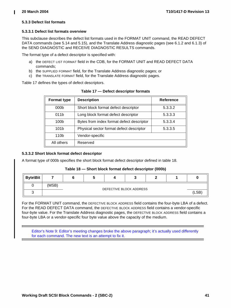
20 March 2004 T10/1417-D Revision 13
Working Draft SCSI Block Commands - 2 (SBC-2) 41
5.3.3 Defect list formats
5.3.3.1 Defect list formats overview
This subclause describes the defect list formats used in the FORMAT UNIT command, the READ DEFECT DATA commands (see 5.14 and 5.15), and the Translate Address diagnostic pages (see 6.1.2 and 6.1.3) of the SEND DIAGNOSTIC and RECEIVE DIAGNOSTIC RESULTS commands.
The format type of a defect descriptor is specified with:
a) the DEFECT LIST FORMAT field in the CDB, for the FORMAT UNIT and READ DEFECT DATA commands;
b) the SUPPLIED FORMAT field, for the Translate Address diagnostic pages; orc) the TRANSLATE FORMAT field, for the Translate Address diagnostic pages.
Table 17 defines the types of defect descriptors.
5.3.3.2 Short block format defect descriptor
A format type of 000b specifies the short block format defect descriptor defined in table 18.
For the FORMAT UNIT command, the DEFECTIVE BLOCK ADDRESS field contains the four-byte LBA of a defect. For the READ DEFECT DATA command, the DEFECTIVE BLOCK ADDRESS field contains a vendor-specific four-byte value. For the Translate Address diagnostic pages, the DEFECTIVE BLOCK ADDRESS field contains a four-byte LBA or a vendor-specific four byte value above the capacity of the medium.
Editor’s Note 9: Editor’s meeting changes broke the above paragraph; it’s actually used differently for each command. The new text is an attempt to fix it.
Table 17 — Defect descriptor formats
Format type Description Reference
000b Short block format defect descriptor 5.3.3.2
011b Long block format defect descriptor 5.3.3.3
100b Bytes from index format defect descriptor 5.3.3.4
101b Physical sector format defect descriptor 5.3.3.5
110b Vendor-specific
All others Reserved
Table 18 — Short block format defect descriptor (000b)
Byte\Bit 7 6 5 4 3 2 1 0
0 (MSB)DEFECTIVE BLOCK ADDRESS
3 (LSB)

T10/1417-D Revision 13 20 March 2004
42 Working Draft SCSI Block Commands - 2 (SBC-2)
5.3.3.3 Long block format defect descriptor
A format type of 011b specifies the long block format defect descriptor defined in table 19.
For the FORMAT UNIT command, the DEFECTIVE BLOCK ADDRESS field contains the eight-byte logical block address of a defect. For the READ DEFECT DATA command, the DEFECTIVE BLOCK ADDRESS field contains a vendor-specific eight-byte value. For the Translate Address diagnostic pages, the DEFECTIVE BLOCK ADDRESS field contains a four-byte LBA or a vendor-specific four byte value above the capacity of the medium.
Editor’s Note 10: Editor’s meeting changes broke the above paragraph; it’s actually used differently for each command. The new text is an attempt to fix it.
5.3.3.4 Bytes from index format defect descriptor
A format type of 100b specifies the bytes from index defect descriptor defined in table 20. This descriptor specifies the location of a defect that is no more than eight bytes long.
The CYLINDER NUMBER OF DEFECT field contains the cylinder number of the defect.
The HEAD NUMBER OF DEFECT field contains the head number of the defect.
The DEFECT BYTES FROM INDEX field contains the number of bytes from the index to the defect.
The defect descriptors shall be in ascending order. The cylinder number of the defect is the most significant part of the address and the defect bytes from index is the least significant part of the address. More than one logical block may be affected by each defect. A DEFECT BYTES FROM INDEX field set to FFFFFFFFh specifies that the entire track shall be considered defective.
Table 19 — Long block format defect descriptor (011b)
Byte\Bit 7 6 5 4 3 2 1 0
0 (MSB)DEFECTIVE BLOCK ADDRESS
7 (LSB)
Table 20 — Bytes from index format defect descriptor (100b)
Byte\Bit 7 6 5 4 3 2 1 0
0 (MSB)CYLINDER NUMBER OF DEFECT
2 (LSB)
3 HEAD NUMBER OF DEFECT
4 (MSB)DEFECT BYTES FROM INDEX
7 (LSB)
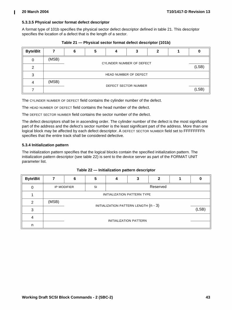
20 March 2004 T10/1417-D Revision 13
Working Draft SCSI Block Commands - 2 (SBC-2) 43
5.3.3.5 Physical sector format defect descriptor
A format type of 101b specifies the physical sector defect descriptor defined in table 21. This descriptor specifies the location of a defect that is the length of a sector.
The CYLINDER NUMBER OF DEFECT field contains the cylinder number of the defect.
The HEAD NUMBER OF DEFECT field contains the head number of the defect.
The DEFECT SECTOR NUMBER field contains the sector number of the defect.
The defect descriptors shall be in ascending order. The cylinder number of the defect is the most significant part of the address and the defect’s sector number is the least significant part of the address. More than one logical block may be affected by each defect descriptor. A DEFECT SECTOR NUMBER field set to FFFFFFFFh specifies that the entire track shall be considered defective.
5.3.4 Initialization pattern
The initialization pattern specifies that the logical blocks contain the specified initialization pattern. The initialization pattern descriptor (see table 22) is sent to the device server as part of the FORMAT UNIT parameter list.
Table 21 — Physical sector format defect descriptor (101b)
Byte\Bit 7 6 5 4 3 2 1 0
0 (MSB)CYLINDER NUMBER OF DEFECT
2 (LSB)
3 HEAD NUMBER OF DEFECT
4 (MSB)DEFECT SECTOR NUMBER
7 (LSB)
Table 22 — Initialization pattern descriptor
Byte\Bit 7 6 5 4 3 2 1 0
0 IP MODIFIER SI Reserved
1 INITIALIZATION PATTERN TYPE
2 (MSB)INITIALIZATION PATTERN LENGTH (n - 3)
3 (LSB)
4INITIALIZATION PATTERN
n
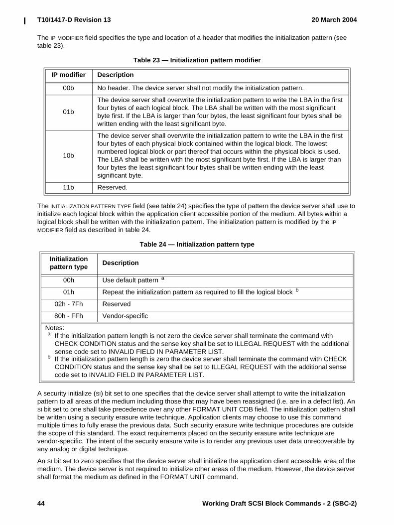
T10/1417-D Revision 13 20 March 2004
44 Working Draft SCSI Block Commands - 2 (SBC-2)
The IP MODIFIER field specifies the type and location of a header that modifies the initialization pattern (see table 23).
The INITIALIZATION PATTERN TYPE field (see table 24) specifies the type of pattern the device server shall use to initialize each logical block within the application client accessible portion of the medium. All bytes within a logical block shall be written with the initialization pattern. The initialization pattern is modified by the IP MODIFIER field as described in table 24.
A security initialize (SI) bit set to one specifies that the device server shall attempt to write the initialization pattern to all areas of the medium including those that may have been reassigned (i.e. are in a defect list). An SI bit set to one shall take precedence over any other FORMAT UNIT CDB field. The initialization pattern shall be written using a security erasure write technique. Application clients may choose to use this command multiple times to fully erase the previous data. Such security erasure write technique procedures are outside the scope of this standard. The exact requirements placed on the security erasure write technique are vendor-specific. The intent of the security erasure write is to render any previous user data unrecoverable by any analog or digital technique.
An SI bit set to zero specifies that the device server shall initialize the application client accessible area of the medium. The device server is not required to initialize other areas of the medium. However, the device server shall format the medium as defined in the FORMAT UNIT command.
Table 23 — Initialization pattern modifier
IP modifier Description
00b No header. The device server shall not modify the initialization pattern.
01b
The device server shall overwrite the initialization pattern to write the LBA in the first four bytes of each logical block. The LBA shall be written with the most significant byte first. If the LBA is larger than four bytes, the least significant four bytes shall be written ending with the least significant byte.
10b
The device server shall overwrite the initialization pattern to write the LBA in the first four bytes of each physical block contained within the logical block. The lowest numbered logical block or part thereof that occurs within the physical block is used. The LBA shall be written with the most significant byte first. If the LBA is larger than four bytes the least significant four bytes shall be written ending with the least significant byte.
11b Reserved.
Table 24 — Initialization pattern type
Initialization pattern type Description
00h Use default pattern a
01h Repeat the initialization pattern as required to fill the logical block b
02h - 7Fh Reserved
80h - FFh Vendor-specific
Notes:a If the initialization pattern length is not zero the device server shall terminate the command with
CHECK CONDITION status and the sense key shall be set to ILLEGAL REQUEST with the additional sense code set to INVALID FIELD IN PARAMETER LIST.
b If the initialization pattern length is zero the device server shall terminate the command with CHECK CONDITION status and the sense key shall be set to ILLEGAL REQUEST with the additional sense code set to INVALID FIELD IN PARAMETER LIST.

20 March 2004 T10/1417-D Revision 13
Working Draft SCSI Block Commands - 2 (SBC-2) 45
When the SI bit is set to one, the device server need not write the initialization pattern over the header and other header and other parts of the medium not previously accessible to the application client. If the device server is unable to write over any area of the medium that is currently accessible to the application client or may be made accessible to the application client in the future (e.g., by clearing the defect list), it shall terminate the command with CHECK CONDITION status and the sense key shall be set to MEDIUM ERROR with the appropriate additional sense code for the condition. The device server shall attempt to rewrite all remaining parts of the medium even if some portions are not able to be rewritten.
The INITIALIZATION PATTERN LENGTH field specifies the number of bytes contained in the initialization pattern. If the length exceeds the current block length the device server shall terminate the command with CHECK CONDITION status and the sense key shall be set to ILLEGAL REQUEST with the additional sense code set to INVALID FIELD IN PARAMETER LIST. The pattern is modified by the IP MODIFIER field.
The INITIALIZATION PATTERN field specifies the initialization pattern.
5.4 LOCK UNLOCK CACHE (10) commandThe LOCK UNLOCK CACHE (10) command (see table 25) requests that the device server disallow or allow logical blocks within the specified range to be removed from the cache memory by the device server's cache replacement algorithm. Locked logical blocks may be written to the medium when modified, but a copy of the modified logical block shall remain in the cache memory.
A LOCK bit set to zero specifies that all logical blocks in the specified range that are currently locked into the cache memory shall be unlocked and may or may not be removed. A LOCK bit set to one specifies that any logical block in the specified range that is currently present in the cache memory shall be locked into cache memory. Only logical blocks that are already present in the cache memory are actually locked.
The LOGICAL BLOCK ADDRESS field specifies the first logical block of the range of logical blocks for this command. If the logical block address exceeds the capacity of the medium the device server shall return CHECK CONDITION status with the sense key set to ILLEGAL REQUEST and the additional sense code set to LOGICAL BLOCK ADDRESS OUT OF RANGE.
The NUMBER OF BLOCKS field specifies the number of contiguous logical blocks within the range. A NUMBER OF BLOCKS field set to zero specifies that the range contains all remaining logical blocks on the medium. Any other value specifies the number of logical blocks within the range. If the logical block address plus the number of blocks exceeds the capacity of the medium, the device server shall return CHECK CONDITION status with the sense key set to ILLEGAL REQUEST and the additional sense code set to LOGICAL BLOCK ADDRESS OUT OF RANGE.
Multiple locks may be in effect from more than one initiator port. Locks from different initiator ports may overlap. An unlock of an overlapped area does not release the lock of another initiator port.
Table 25 — LOCK UNLOCK CACHE (10) command
Byte\Bit 7 6 5 4 3 2 1 0
0 OPERATION CODE (36h)
1 Reserved LOCK Obsolete
2 (MSB)LOGICAL BLOCK ADDRESS
5 (LSB)
6 Reserved
7 (MSB)NUMBER OF BLOCKS
8 (LSB)
9 CONTROL

T10/1417-D Revision 13 20 March 2004
46 Working Draft SCSI Block Commands - 2 (SBC-2)
5.5 LOCK UNLOCK CACHE (16) commandThe LOCK UNLOCK CACHE (16) command (see table 26) requests that the device server disallow or allow logical blocks within the specified range to be removed from the cache memory by the device server's cache replacement algorithm.
See the LOCK UNLOCK CACHE (10) command (see 5.4) for a description of the fields in this command.
5.6 PRE-FETCH (10) commandThe PRE-FETCH (10) command (see table 27) requests that the device server transfer the specified logical blocks from the medium to the cache memory. No data shall be transferred to the application client.
An immediate (IMMED) bit set to zero specifies that status shall be returned after the operation is complete. An IMMED bit set to one specifies that status shall be returned as soon as the CDB has been validated.
See the LOCK UNLOCK CACHE (10) command (see 5.4) for a definition of the LOGICAL BLOCK ADDRESS field.
The PREFETCH LENGTH field specifies the number of contiguous logical blocks of data that shall be transferred to the block device's cache memory from the medium. A PREFETCH LENGTH field set to zero specifies that all remaining logical blocks shall be transferred to the cache memory. Any other value specifies the number of logical blocks that shall be transferred. If the logical block address plus the prefetch length exceeds the capacity of the medium, the device server shall return CHECK CONDITION status with the sense key set to ILLEGAL REQUEST and the additional sense code set to LOGICAL BLOCK ADDRESS OUT OF RANGE.The device server is not required to transfer logical blocks that already are contained in the cache memory.
Table 26 — LOCK UNLOCK CACHE (16) command
Byte\Bit 7 6 5 4 3 2 1 0
0 OPERATION CODE (92h)
1 Reserved LOCK Reserved
2 (MSB)LOGICAL BLOCK ADDRESS
9 (LSB)
10 (MSB)NUMBER OF BLOCKS
13 (LSB)
14 Reserved
15 CONTROL
Table 27 — PRE-FETCH (10) command
Byte\Bit 7 6 5 4 3 2 1 0
0 OPERATION CODE (34h)
1 Reserved IMMED Obsolete
2 (MSB)LOGICAL BLOCK ADDRESS
5 (LSB)
6 Reserved
7 (MSB)PREFETCH LENGTH
8 (LSB)
9 CONTROL

20 March 2004 T10/1417-D Revision 13
Working Draft SCSI Block Commands - 2 (SBC-2) 47
If the IMMED bit is set to zero and the specified logical blocks were successfully transferred to the cache memory, the device server shall return:
a) CONDITION MET status if the LINK bit is set to zero in the CONTROL byte (see SPC-3); orb) INTERMEDIATE-CONDITION MET status if the LINK bit is set to one.
If the IMMED bit is set to zero and the unlocked cache memory does not have sufficient capacity to accept all of the specified logical blocks, the device server shall transfer to the cache memory as many of the specified logical blocks that fit. If these logical blocks are transferred successfully it shall return:
a) GOOD status if the LINK bit is set to zero in the CONTROL byte (see SPC-3); orb) INTERMEDIATE status if the LINK bit is set to one.
If the IMMED bit is set to one and the unlocked cache memory has sufficient capacity to accept all of the specified logical blocks, the device server shall return:
a) CONDITION MET status if the LINK bit is set to zero in the CONTROL byte (see SPC-3); orb) INTERMEDIATE-CONDITION MET status if the LINK bit is set to ine.
If the IMMED bit is set to one and the unlocked cache memory does not have sufficient capacity to accept all of the specified logical blocks, the device server shall return:
a) GOOD status if the LINK bit is set to zero in the CONTROL byte (see SPC-3); orb) INTERMEDIATE status if the LINK bit is set to one.
If the IMMED bit is set to zero and one or more of the specified logical blocks were not successfully transferred to the cache memory for reasons other than lack of cache memory capacity, the device server shall return CHECK CONDITION status with the appropriate sense key and additional sense code. If the IMMED bit is set to one and one or more of the specified logical blocks were not successfully transferred to the cache memory for reasons other than lack of cache memory capacity, the device server shall report a deferred error (see SPC-3).
5.7 PRE-FETCH (16) commandThe PRE-FETCH (16) command (see table 28) requests that the device server transfer the specified logical blocks from the medium to the cache memory. No data shall be transferred to the application client.
See the PRE-FETCH (10) command (see 5.6) for a description of the fields in this command.
Table 28 — PRE-FETCH (16) command
Byte\Bit 7 6 5 4 3 2 1 0
0 OPERATION CODE (90h)
1 Reserved IMMED Reserved
2 (MSB)LOGICAL BLOCK ADDRESS
9 (LSB)
10 (MSB)PREFETCH LENGTH
13 (LSB)
14 Reserved
15 CONTROL

T10/1417-D Revision 13 20 March 2004
48 Working Draft SCSI Block Commands - 2 (SBC-2)
5.8 READ (6) commandThe READ (6) command (see table 29) requests that the device server transfer data, including user data but not including protection information, to the application client. The most recent data value written, or to be written if cached, in the addressed logical block shall be returned.
The cache control bits (see 5.9) are not provided for this command. Block devices with cache memory may have values for the cache control bits that affect the READ (6) command; however, no default values are defined by this standard. If explicit control is required, the READ (10) command should be used.
The LOGICAL BLOCK ADDRESS field specifies the logical block where the read operation shall begin.
The TRANSFER LENGTH field specifies the number of contiguous logical blocks of data to be transferred. A TRANSFER LENGTH field set to zero specifies that 256 logical blocks shall be transferred. Any other value specifies the number of logical blocks that shall be transferred. If the logical block address plus the transfer length exceeds the capacity of the medium, the device server shall return CHECK CONDITION status with the sense key set to ILLEGAL REQUEST and the additional sense code set to LOGICAL BLOCK ADDRESS OUT OF RANGE. The TRANSFER LENGTH field is constrained by the MAXIMUM TRANSFER LENGTH field in the Block Limits VPD page (see 6.4.2).
NOTE 8 - Although the READ (6) command is limited to directly addressing logical blocks up to a capacity of 2 Gigabytes, for block lengths of 512 bytes, this command has been maintained as mandatory since some system initialization routines require that the READ (6) command be used. Application clients should migrate from the READ (6) command to the READ (10) command which may address 2 Terabytes with block lengths of 512 bytes, or the READ (16) command to address more than 2 Terabytes.
NOTE 9 - For the READ (10) command, READ (12) command, and READ (16) command, a TRANSFER LENGTH field set to zero specifies that no logical blocks are transferred.
Table 29 — READ (6) command
Byte\Bit 7 6 5 4 3 2 1 0
0 OPERATION CODE (08h)
1 Reserved (MSB)
2 LOGICAL BLOCK ADDRESS
3 (LSB)
4 TRANSFER LENGTH
5 CONTROL
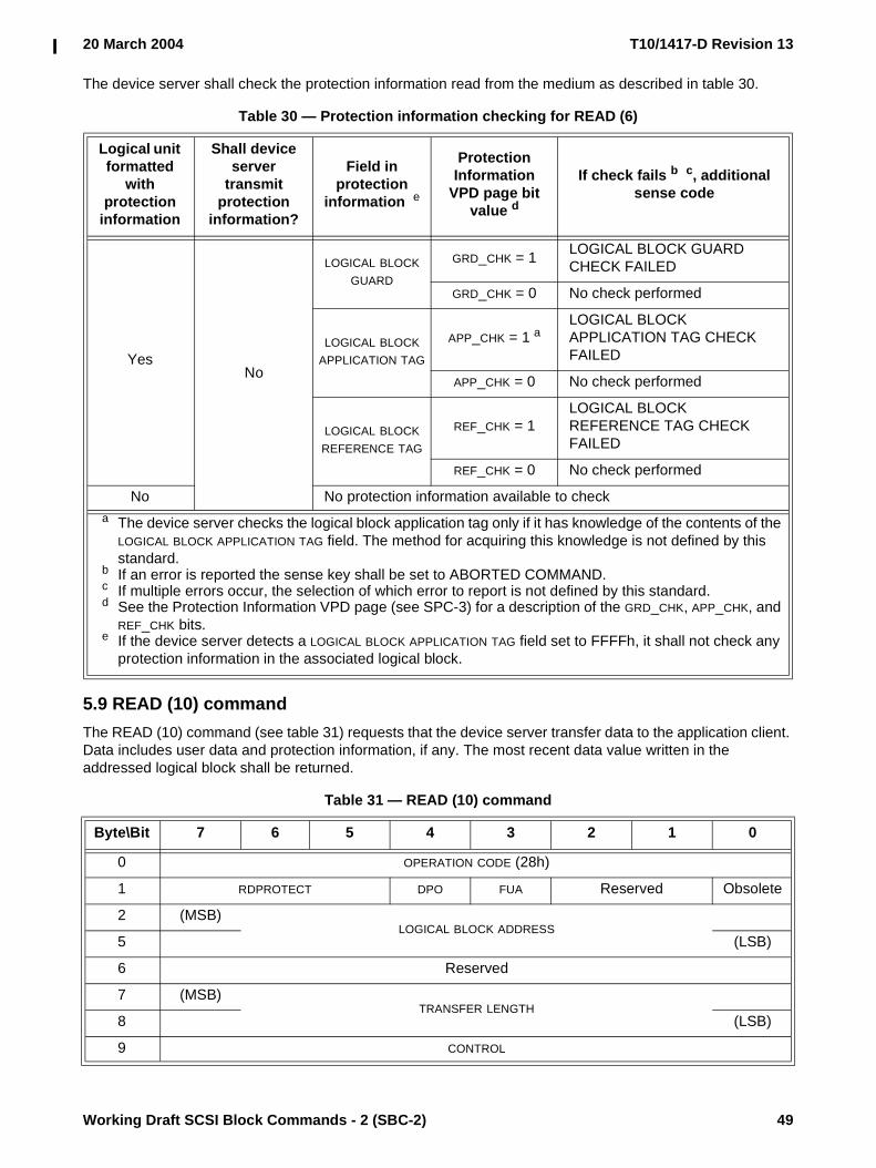
20 March 2004 T10/1417-D Revision 13
Working Draft SCSI Block Commands - 2 (SBC-2) 49
The device server shall check the protection information read from the medium as described in table 30.
5.9 READ (10) commandThe READ (10) command (see table 31) requests that the device server transfer data to the application client. Data includes user data and protection information, if any. The most recent data value written in the addressed logical block shall be returned.
Table 30 — Protection information checking for READ (6)
Logical unit formatted
with protection
information
Shall device server
transmit protection
information?
Field in protection
information e
Protection Information
VPD page bit value d
If check fails b c, additional sense code
YesNo
LOGICAL BLOCK GUARD
GRD_CHK = 1 LOGICAL BLOCK GUARD CHECK FAILED
GRD_CHK = 0 No check performed
LOGICAL BLOCK APPLICATION TAG
APP_CHK = 1 aLOGICAL BLOCK APPLICATION TAG CHECK FAILED
APP_CHK = 0 No check performed
LOGICAL BLOCK REFERENCE TAG
REF_CHK = 1LOGICAL BLOCK REFERENCE TAG CHECK FAILED
REF_CHK = 0 No check performed
No No protection information available to checka The device server checks the logical block application tag only if it has knowledge of the contents of the
LOGICAL BLOCK APPLICATION TAG field. The method for acquiring this knowledge is not defined by this standard.
b If an error is reported the sense key shall be set to ABORTED COMMAND.c If multiple errors occur, the selection of which error to report is not defined by this standard.d See the Protection Information VPD page (see SPC-3) for a description of the GRD_CHK, APP_CHK, and
REF_CHK bits.e If the device server detects a LOGICAL BLOCK APPLICATION TAG field set to FFFFh, it shall not check any
protection information in the associated logical block.
Table 31 — READ (10) command
Byte\Bit 7 6 5 4 3 2 1 0
0 OPERATION CODE (28h)
1 RDPROTECT DPO FUA Reserved Obsolete
2 (MSB)LOGICAL BLOCK ADDRESS
5 (LSB)
6 Reserved
7 (MSB)TRANSFER LENGTH
8 (LSB)
9 CONTROL

T10/1417-D Revision 13 20 March 2004
50 Working Draft SCSI Block Commands - 2 (SBC-2)
See the LOCK UNLOCK CACHE (10) command (see 5.4) for a definition of the LOGICAL BLOCK ADDRESS field.
The device server shall check the protection information read from the medium based on the RDPROTECT field as described in table 32.
Table 32 — RDPROTECT field (part 1 of 3)
Value
Logical unit
formatted with
protection information
Shall device server
transmit protection
information?
Field in protection
information h
Protection Information
VPD page bit value g
If check fails d f, additional sense code
000bYes
No
LOGICAL BLOCK GUARD
GRD_CHK = 1 LOGICAL BLOCK GUARD CHECK FAILED
GRD_CHK = 0 No check performed
LOGICAL BLOCK APPLICATION
TAG
APP_CHK = 1 cLOGICAL BLOCK APPLICATION TAG CHECK FAILED
APP_CHK = 0 No check performed
LOGICAL BLOCK REFERENCE
TAG
REF_CHK = 1LOGICAL BLOCK REFERENCE TAG CHECK FAILED
REF_CHK = 0 No check performed
No No protection information available to checka A read operation to a logical unit that supports protection information (see 4.15) and has not been
formatted with protection information shall fail with a CHECK CONDITION status. The sense key shall be set to ILLEGAL REQUEST with the additional sense code set to INVALID FIELD IN CDB.
b If the logical unit does not support protection information the requested command should fail with CHECK CONDITION status with a sense key of ILLEGAL REQUEST and an additional sense code of INVALID FIELD IN CDB.
c The device server checks the logical block application tag only if it has knowledge of the contents of the LOGICAL BLOCK APPLICATION TAG field. The method for acquiring this knowledge is not defined by this standard.
d If an error is reported the sense key shall be set to ABORTED COMMAND.e Transmit protection information to the application client.f If multiple errors occur, the selection of which error to report is not defined by this standard.g See the Protection Information VPD page (see SPC-3) for a description of the GRD_CHK, APP_CHK, and
REF_CHK bits.h If the application client or device server detects a LOGICAL BLOCK APPLICATION TAG field set to FFFFh,
the checking of all protection information in the associated logical block shall be disabled.

20 March 2004 T10/1417-D Revision 13
Working Draft SCSI Block Commands - 2 (SBC-2) 51
001b bYes Yes e
LOGICAL BLOCK GUARD
GRD_CHK = 1 LOGICAL BLOCK GUARD CHECK FAILED
GRD_CHK = 0 No check performed
LOGICAL BLOCK APPLICATION
TAG
APP_CHK = 1 cLOGICAL BLOCK APPLICATION TAG CHECK FAILED
APP_CHK = 0 No check performed
LOGICAL BLOCK REFERENCE
TAG
REF_CHK = 1LOGICAL BLOCK REFERENCE TAG CHECK FAILED
REF_CHK = 0 No check performed
No a No protection information available to transmit to the application client or for checking
Table 32 — RDPROTECT field (part 2 of 3)
Value
Logical unit
formatted with
protection information
Shall device server
transmit protection
information?
Field in protection
information h
Protection Information
VPD page bit value g
If check fails d f, additional sense code
a A read operation to a logical unit that supports protection information (see 4.15) and has not been formatted with protection information shall fail with a CHECK CONDITION status. The sense key shall be set to ILLEGAL REQUEST with the additional sense code set to INVALID FIELD IN CDB.
b If the logical unit does not support protection information the requested command should fail with CHECK CONDITION status with a sense key of ILLEGAL REQUEST and an additional sense code of INVALID FIELD IN CDB.
c The device server checks the logical block application tag only if it has knowledge of the contents of the LOGICAL BLOCK APPLICATION TAG field. The method for acquiring this knowledge is not defined by this standard.
d If an error is reported the sense key shall be set to ABORTED COMMAND.e Transmit protection information to the application client.f If multiple errors occur, the selection of which error to report is not defined by this standard.g See the Protection Information VPD page (see SPC-3) for a description of the GRD_CHK, APP_CHK, and
REF_CHK bits.h If the application client or device server detects a LOGICAL BLOCK APPLICATION TAG field set to FFFFh,
the checking of all protection information in the associated logical block shall be disabled.

T10/1417-D Revision 13 20 March 2004
52 Working Draft SCSI Block Commands - 2 (SBC-2)
A disable page out (DPO) bit set to zero specifies that the retention priority shall be determined by the RETENTION PRIORITY fields in the Caching mode page (see 6.3.2). A DPO bit set to one specifies that the device
010b bYes Yes e
LOGICAL BLOCK GUARD
Shall not No check performed
LOGICAL BLOCK APPLICATION
TAG
APP_CHK = 1 c hLOGICAL BLOCK APPLICATION TAG CHECK FAILED
APP_CHK = 0 No check performed
LOGICAL BLOCK REFERENCE
TAG
REF_CHK = 1 hLOGICAL BLOCK REFERENCE TAG CHECK FAILED
REF_CHK = 0 No check performed
No a No protection information available to transmit to the application client or for checking
011b bYes Yes e
LOGICAL BLOCK GUARD
Shall not No check performed
LOGICAL BLOCK APPLICATION
TAGShall not No check performed
LOGICAL BLOCK REFERENCE
TAGShall not No check performed
No a No protection information available to transmit to the application client or for checking
100b - 111b Reserved
Table 32 — RDPROTECT field (part 3 of 3)
Value
Logical unit
formatted with
protection information
Shall device server
transmit protection
information?
Field in protection
information h
Protection Information
VPD page bit value g
If check fails d f, additional sense code
a A read operation to a logical unit that supports protection information (see 4.15) and has not been formatted with protection information shall fail with a CHECK CONDITION status. The sense key shall be set to ILLEGAL REQUEST with the additional sense code set to INVALID FIELD IN CDB.
b If the logical unit does not support protection information the requested command should fail with CHECK CONDITION status with a sense key of ILLEGAL REQUEST and an additional sense code of INVALID FIELD IN CDB.
c The device server checks the logical block application tag only if it has knowledge of the contents of the LOGICAL BLOCK APPLICATION TAG field. The method for acquiring this knowledge is not defined by this standard.
d If an error is reported the sense key shall be set to ABORTED COMMAND.e Transmit protection information to the application client.f If multiple errors occur, the selection of which error to report is not defined by this standard.g See the Protection Information VPD page (see SPC-3) for a description of the GRD_CHK, APP_CHK, and
REF_CHK bits.h If the application client or device server detects a LOGICAL BLOCK APPLICATION TAG field set to FFFFh,
the checking of all protection information in the associated logical block shall be disabled.

20 March 2004 T10/1417-D Revision 13
Working Draft SCSI Block Commands - 2 (SBC-2) 53
server shall assign the logical blocks accessed by this command the lowest retention priority for being fetched into or retained by the cache. A DPO bit set to one overrides any retention priority specified in the Caching mode page. All other aspects of the algorithm implementing the cache memory replacement strategy are not defined by this standard.
NOTE 10 - The DPO bit is used to control replacement of logical blocks in the cache memory when the appli-cation client has information on the future usage of the logical blocks. If the DPO bit is set to one, the appli-cation client is specifying that the logical blocks accessed by the command are not likely to be accessed again in the near future and should not be put in the cache memory nor retained by the cache memory. If the DPO bit is set to zero, the application client is specifying that the logical blocks accessed by this command are likely to be accessed again in the near future.
A force unit access (FUA) bit set to zero specifies that the device server may provide the data from cache memory. For read operations, any logical blocks that are contained in the cache memory may be transferred to the application client data-in buffer directly from the cache memory. For write operations, logical blocks may be transferred directly from the application client data-out buffer to the cache memory. GOOD status may be returned to the application client prior to writing the logical blocks to the medium. Any error that occurs after the GOOD status is returned is a deferred error, and information regarding the error is not reported until a subsequent command.
An FUA bit set to one specifies that the device server shall provide the data from the medium, not cache memory. Read commands shall access the specified logical blocks from the medium (i.e., the data is not directly retrieved from the cache). If the cache contains a more recent version of a logical block than the medium, the logical block shall first be written to the medium. Write commands shall not return GOOD status until the logical blocks have actually been written on the medium (i.e., the data is not write cached). Read commands that cause data to be written to the medium from cache and that encounter an error shall cause a deferred error (see SPC-3) to be reported.
The TRANSFER LENGTH field specifies the number of contiguous logical blocks of data that shall be transferred. A TRANSFER LENGTH field set to zero specifies that no logical blocks shall be transferred. This condition shall not be considered an error. Any other value specifies the number of logical blocks that shall be transferred. If the logical block address plus the transfer length exceeds the capacity of the medium, the device server shall return CHECK CONDITION status with the sense key set to ILLEGAL REQUEST and the additional sense code set to LOGICAL BLOCK ADDRESS OUT OF RANGE. The TRANSFER LENGTH field is constrained by the MAXIMUM TRANSFER LENGTH field in the Block Limits VPD page (see 6.4.2).
NOTE 11 - For the READ (6) command, a TRANSFER LENGTH field set to zero specifies that 256 logical blocks are transferred.

T10/1417-D Revision 13 20 March 2004
54 Working Draft SCSI Block Commands - 2 (SBC-2)
5.10 READ (12) commandThe READ (12) command (see table 33) requests that the device server transfer data to the application client from the medium. Data includes user data and protection information, if any.
See the READ (10) command (see 5.9) for a description of the fields in this command.
5.11 READ (16) commandThe READ (16) command (see table 34) requests that the device server transfer data to the application client from the medium. Data includes user data and protection information, if any.
See the READ (10) command (see 5.9) for a description of the fields in this command.
5.12 READ CAPACITY (10) commandThe READ CAPACITY (10) command (see table 35) provides a means for the application client to request information regarding the capacity of the block device. This command may be processed as if it has a HEAD
Table 33 — READ (12) command
Byte\Bit 7 6 5 4 3 2 1 0
0 OPERATION CODE (A8h)
1 RDPROTECT DPO FUA Reserved Obsolete
2 (MSB)LOGICAL BLOCK ADDRESS
5 (LSB)
6 (MSB)TRANSFER LENGTH
9 (LSB)
10Restricted
for MMC-4
Reserved
11 CONTROL
Table 34 — READ (16) command
Byte\Bit 7 6 5 4 3 2 1 0
0 OPERATION CODE (88h)
1 RDPROTECT DPO FUA Reserved
2 (MSB)LOGICAL BLOCK ADDRESS
9 (LSB)
10 (MSB)TRANSFER LENGTH
13 (LSB)
14Restricted
for MMC-4
Reserved
15 CONTROL

20 March 2004 T10/1417-D Revision 13
Working Draft SCSI Block Commands - 2 (SBC-2) 55
OF QUEUE task attribute (see 4.7). If the logical unit supports protection information (see 4.5), the READ CAPACITY (16) command should be used instead of READ CAPACITY (10).
See the LOCK UNLOCK CACHE (10) command (see 5.4) for a definition of the LOGICAL BLOCK ADDRESS field.
The LOGICAL BLOCK ADDRESS field shall be zero if the PMI bit is set to zero. If the PMI bit is set to zero and the LOGICAL BLOCK ADDRESS field is not set to zero, the device server shall return a CHECK CONDITION status and the sense key shall be set to ILLEGAL REQUEST with the additional sense code set to ILLEGAL FIELD IN CDB.
A partial medium indicator (PMI) bit set to zero specifies that the device server return information on the last logical block on the block device.
A PMI bit set to one specifies that the device server return information on the last logical block after that specified in the LOGICAL BLOCK ADDRESS field before a substantial vendor-specific delay in data transfer may be encountered.
NOTE 12 - This function is intended to assist storage management software in determining whether there is sufficient space starting with the logical block address specified in the CDB to contain a frequently accessed data structure (e.g., a file directory or file index) without incurring an extra delay.
The short read capacity data is defined in table 36.
If the number of logical blocks exceeds the maximum value that may be specified in the RETURNED LOGICAL BLOCK ADDRESS field, the device server shall set the RETURNED LOGICAL BLOCK ADDRESS field to FFFFFFFFh. The initiator should then issue a READ CAPACITY (16) command.
If the PMI bit is set to zero, the device server shall set the RETURNED LOGICAL BLOCK ADDRESS field to the lower of:
a) the LBA of the last logical block on the block device; orb) FFFFFFFFh.
Table 35 — READ CAPACITY (10) command
Byte\Bit 7 6 5 4 3 2 1 0
0 OPERATION CODE (25h)
1 Reserved Obsolete
2 (MSB)LOGICAL BLOCK ADDRESS
5 (LSB)
6Reserved
7
8 Reserved PMI
9 CONTROL
Table 36 — Short read capacity data
Byte\Bit 7 6 5 4 3 2 1 0
0 (MSB)RETURNED LOGICAL BLOCK ADDRESS
3 (LSB)
4 (MSB)BLOCK LENGTH IN BYTES
7 (LSB)
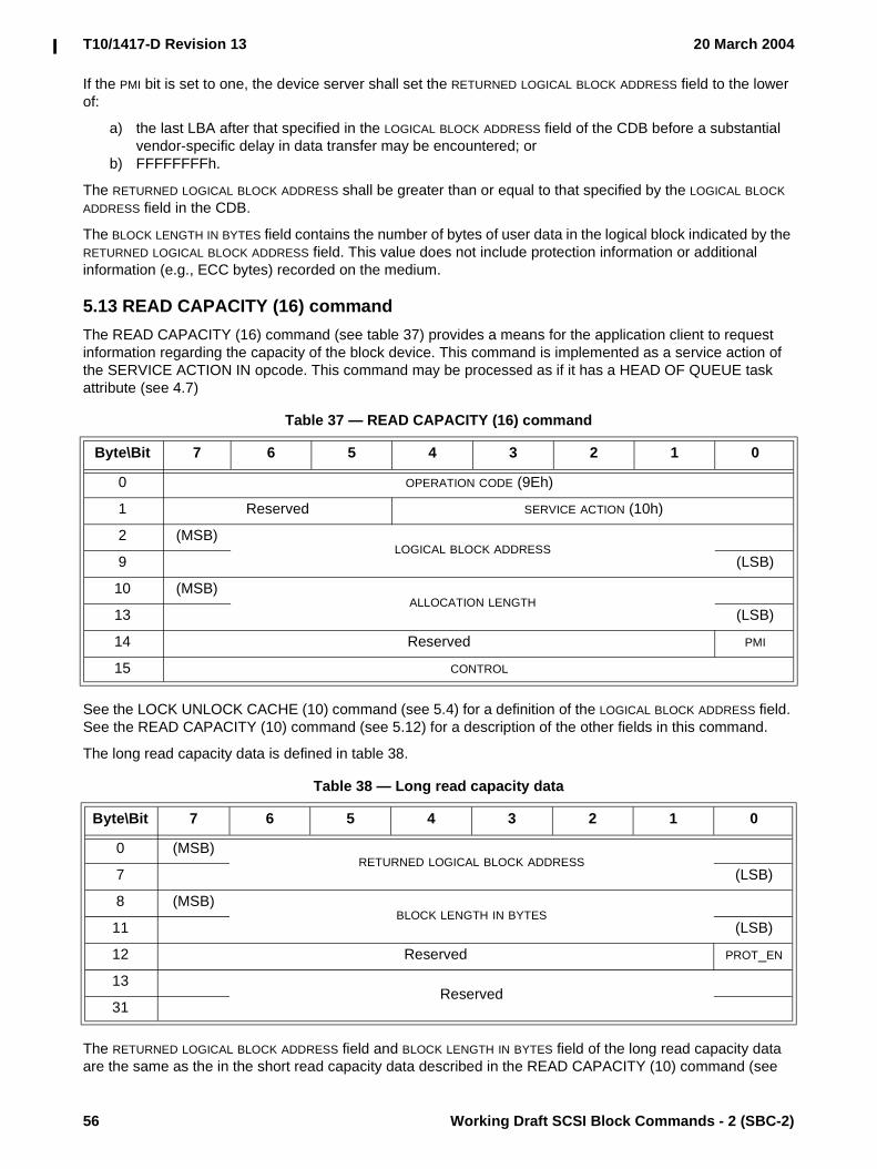
T10/1417-D Revision 13 20 March 2004
56 Working Draft SCSI Block Commands - 2 (SBC-2)
If the PMI bit is set to one, the device server shall set the RETURNED LOGICAL BLOCK ADDRESS field to the lower of:
a) the last LBA after that specified in the LOGICAL BLOCK ADDRESS field of the CDB before a substantial vendor-specific delay in data transfer may be encountered; or
b) FFFFFFFFh.
The RETURNED LOGICAL BLOCK ADDRESS shall be greater than or equal to that specified by the LOGICAL BLOCK ADDRESS field in the CDB.
The BLOCK LENGTH IN BYTES field contains the number of bytes of user data in the logical block indicated by the RETURNED LOGICAL BLOCK ADDRESS field. This value does not include protection information or additional information (e.g., ECC bytes) recorded on the medium.
5.13 READ CAPACITY (16) commandThe READ CAPACITY (16) command (see table 37) provides a means for the application client to request information regarding the capacity of the block device. This command is implemented as a service action of the SERVICE ACTION IN opcode. This command may be processed as if it has a HEAD OF QUEUE task attribute (see 4.7)
See the LOCK UNLOCK CACHE (10) command (see 5.4) for a definition of the LOGICAL BLOCK ADDRESS field. See the READ CAPACITY (10) command (see 5.12) for a description of the other fields in this command.
The long read capacity data is defined in table 38.
The RETURNED LOGICAL BLOCK ADDRESS field and BLOCK LENGTH IN BYTES field of the long read capacity data are the same as the in the short read capacity data described in the READ CAPACITY (10) command (see
Table 37 — READ CAPACITY (16) command
Byte\Bit 7 6 5 4 3 2 1 0
0 OPERATION CODE (9Eh)
1 Reserved SERVICE ACTION (10h)
2 (MSB)LOGICAL BLOCK ADDRESS
9 (LSB)
10 (MSB)ALLOCATION LENGTH
13 (LSB)
14 Reserved PMI
15 CONTROL
Table 38 — Long read capacity data
Byte\Bit 7 6 5 4 3 2 1 0
0 (MSB)RETURNED LOGICAL BLOCK ADDRESS
7 (LSB)
8 (MSB)BLOCK LENGTH IN BYTES
11 (LSB)
12 Reserved PROT_EN
13Reserved
31

20 March 2004 T10/1417-D Revision 13
Working Draft SCSI Block Commands - 2 (SBC-2) 57
5.12). The maximum value that shall be returned in the RETURNED LOGICAL BLOCK ADDRESS field is FFFFFFFF FFFFFFFEh.
A PROT_EN bit set to one indicates that the medium was formatted with protection information (see 4.15) enabled. A PROT_EN bit set to zero indicates that the medium was not formatted with protection information enabled.
5.14 READ DEFECT DATA (10) commandThe READ DEFECT DATA (10) command (see table 39) requests that the device server transfer the medium defect data to the application client.
If the device server is unable to access the medium defect data, it shall terminate the command with CHECK CONDITION status. The sense key shall be set to either MEDIUM ERROR, if a medium error occurred, or NO SENSE, if the list does not exist. The additional sense code set to DEFECT LIST NOT FOUND.
NOTE 13 - Some device servers may not be able to return medium defect data until after a FORMAT UNIT command (see 5.3) has been completed successfully.
A request primary defect list (REQ_PLIST) bit set to zero specifies that the device server shall not return the PLIST. A REQ_PLIST bit set to one specifies that the device server shall return the PLIST, if any.
A request grown defect list (REQ_GLIST) bit set to zero specifies that the device server shall not return the GLIST. A REQ_GLIST bit set to one specifies that the device server shall return the GLIST, if any.
A REQ_PLIST bit set to zero and a REQ_GLIST bit set to zero specifies that the device server shall return only the defect list header.
A REQ_PLIST bit set to one and a REQ_GLIST bit set to one specifies that the device server shall return both the PLIST and GLIST, if any. The order the lists are returned in is vendor-specific. Whether the lists are merged or not is vendor-specific.
The DEFECT LIST FORMAT field is used by the application client to specify the preferred format for the defect list. This field is intended for those device servers capable of returning more than one format, as defined in the FORMAT UNIT command (see 5.3.3). A device server unable to return the requested format shall return the defect list in its default format (see the DEFECT LIST FORMAT field in the defect list header).
If the requested defect list format and the returned defect list format are not the same, the device server shall transfer the defect data and then terminate the command with CHECK CONDITION status and the sense key shall be set to RECOVERED ERROR with the additional sense code set to DEFECT LIST NOT FOUND.
Table 39 — READ DEFECT DATA (10) command
Byte\Bit 7 6 5 4 3 2 1 0
0 OPERATION CODE (37h)
1 Reserved
2 Reserved REQ_PLIST REQ_GLIST DEFECT LIST FORMAT
3Reserved
6
7 (MSB)ALLOCATION LENGTH
8 (LSB)
9 CONTROL
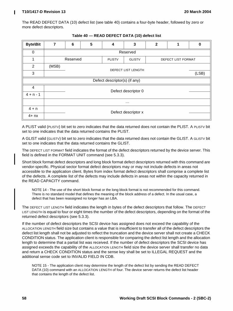
T10/1417-D Revision 13 20 March 2004
58 Working Draft SCSI Block Commands - 2 (SBC-2)
The READ DEFECT DATA (10) defect list (see table 40) contains a four-byte header, followed by zero or more defect descriptors.
A PLIST valid (PLISTV) bit set to zero indicates that the data returned does not contain the PLIST. A PLISTV bit set to one indicates that the data returned contains the PLIST.
A GLIST valid (GLISTV) bit set to zero indicates that the data returned does not contain the GLIST. A GLISTV bit set to one indicates that the data returned contains the GLIST.
The DEFECT LIST FORMAT field indicates the format of the defect descriptors returned by the device server. This field is defined in the FORMAT UNIT command (see 5.3.3).
Short block format defect descriptors and long block format defect descriptors returned with this command are vendor-specific. Physical sector format defect descriptors may or may not include defects in areas not accessible to the application client. Bytes from index format defect descriptors shall comprise a complete list of the defects. A complete list of the defects may include defects in areas not within the capacity returned in the READ CAPACITY command.
NOTE 14 - The use of the short block format or the long block format is not recommended for this command. There is no standard model that defines the meaning of the block address of a defect. In the usual case, a defect that has been reassigned no longer has an LBA.
The DEFECT LIST LENGTH field indicates the length in bytes of the defect descriptors that follow. The DEFECT LIST LENGTH is equal to four or eight times the number of the defect descriptors, depending on the format of the returned defect descriptors (see 5.3.3).
If the number of defect descriptors the SCSI device has assigned does not exceed the capability of the ALLOCATION LENGTH field size but contains a value that is insufficient to transfer all of the defect descriptors the defect list length shall not be adjusted to reflect the truncation and the device server shall not create a CHECK CONDITION status. The application client is responsible for comparing the defect list length and the allocation length to determine that a partial list was received. If the number of defect descriptors the SCSI device has assigned exceeds the capability of the ALLOCATION LENGTH field size the device server shall transfer no data and return a CHECK CONDITION status and the sense key shall be set to ILLEGAL REQUEST and the additional sense code set to INVALID FIELD IN CDB.
NOTE 15 - The application client may determine the length of the defect list by sending the READ DEFECT DATA (10) command with an ALLOCATION LENGTH of four. The device server returns the defect list header that contains the length of the defect list.
Table 40 — READ DEFECT DATA (10) defect list
Byte\Bit 7 6 5 4 3 2 1 0
0 Reserved
1 Reserved PLISTV GLISTV DEFECT LIST FORMAT
2 (MSB)DEFECT LIST LENGTH
3 (LSB)
Defect descriptor(s) (if any)
4Defect descriptor 0
4 + n - 1
…
4 + nDefect descriptor x
4+ nx

20 March 2004 T10/1417-D Revision 13
Working Draft SCSI Block Commands - 2 (SBC-2) 59
The defect descriptors may or may not be sent in ascending order. The application client may determine the exact number of the defects by dividing the DEFECT LIST LENGTH by the length of a single defect descriptor for the returned format.
5.15 READ DEFECT DATA (12) commandThe READ DEFECT DATA (12) command (see table 41) requests that the device server transfer the medium defect data to the application client.
See the READ DEFECT DATA (10) command (5.13) for a description of the fields in this command.
The READ DEFECT DATA (12) defect list (see table 42) contains an eight byte header, followed by zero or more defect descriptors.
See the description of the READ DEFECT DATA (10) list header (see 5.14) for a description of the fields in this header.
Table 41 — READ DEFECT DATA (12) command
Byte\Bit 7 6 5 4 3 2 1 0
0 OPERATION CODE (B7h)
1 Reserved REQ_PLIST REQ_GLIST DEFECT LIST FORMAT
2Reserved
5
6 (MSB)ALLOCATION LENGTH
9 (LSB)
10 Reserved
11 CONTROL
Table 42 — READ DEFECT DATA (12) defect list
Byte\Bit 7 6 5 4 3 2 1 0
0 Reserved
1 Reserved PLISTV GLISTV DEFECT LIST FORMAT
2 Reserved
3 Reserved
4 (MSB)DEFECT LIST LENGTH
7 (LSB)
Defect descriptor(s) (if any)
8Defect descriptor 0
8+ n - 1
…
8+ nDefect descriptor X
8+ nx - 1

T10/1417-D Revision 13 20 March 2004
60 Working Draft SCSI Block Commands - 2 (SBC-2)
5.16 READ LONG (10) commandThe READ LONG (10) command (see table 43) requests that the device server transfer data from a single logical block to the application client. The data passed during the READ LONG (10) command is vendor-specific, but shall include the user data, any protection information, and any additional information (e.g., ECC bytes) recorded on the medium. The most recent data written, or to be written, in the addressed logical block shall be returned. The values in the Read-Write Error Recovery mode page (see 6.3.4) do not apply to this command. The device server may perform retries while processing this command.
See the LOCK UNLOCK CACHE (10) command (see 5.4) for a definition of the LOGICAL BLOCK ADDRESS field.
If the additional bytes contain an ECC code, any other additional bytes that are correctable by ECC should be included (e.g., data synchronization mark within the area covered by ECC). It is not required for the ECC bytes to be at the end of the data bytes; however, they should be in the same order as they are on the medium.
A correct (CORRCT) bit set to zero specifies that a logical block be read without any correction made by the device server. A CORRCT bit set to zero should result in GOOD status unless data is not transferred for some reason other than that the data is non-correctable. In this case the appropriate status and/or sense data shall be set. A CORRCT bit set to one specifies that the data be corrected by ECC before being transferred to the application client data-in buffer.
The BYTE TRANSFER LENGTH field specifies the number of bytes of data that shall be transferred from the specified logical block. If the BYTE TRANSFER LENGTH field is not set to zero and does not match the available data length, the device server shall terminate the command with CHECK CONDITION status with the sense key set to ILLEGAL REQUEST and the additional sense code set to INVALID FIELD IN CDB. In the sense data (see SPC-3), the VALID and ILI bits shall each be set to one and the INFORMATION field shall be set to the difference (i.e., residue) of the requested byte transfer length minus the actual available data length in bytes. Negative values shall be indicated by two's complement notation.
A BYTE TRANSFER LENGTH field set to zero specifies that no bytes shall be transferred. This condition shall not be considered an error.
Table 43 — READ LONG (10) command
Byte\Bit 7 6 5 4 3 2 1 0
0 OPERATION CODE (3Eh)
1 Reserved CORRCT Obsolete
2 (MSB)LOGICAL BLOCK ADDRESS
5 (LSB)
6 Reserved
7 (MSB)BYTE TRANSFER LENGTH
8 (LSB)
9 CONTROL

20 March 2004 T10/1417-D Revision 13
Working Draft SCSI Block Commands - 2 (SBC-2) 61
5.17 READ LONG (16) commandThe READ LONG (16) command (see table 44) equests that the device server transfer data from a single logical block to the application client. This command is implemented as a service action of the SERVICE ACTION IN opcode.
See the READ LONG (10) command (see 5.16) for a description of the fields in this command.
5.18 REASSIGN BLOCKS commandThe REASSIGN BLOCKS command (see table 45) requests the device server to reassign the defective logical blocks to another area on the medium set aside for this purpose. The device server should also record the location of the defective logical blocks in the GLIST if such a list is supported. More than one physical or logical block may be relocated by each defect descriptor sent by the application client. This command shall not alter the contents of the PLIST (see 5.3).
The application client transfers a defect list that contains the LBAs to be reassigned. The device server shall reassign the parts of the medium used for each LBA in the list. The data contained in the logical blocks specified in the defect list may be altered, but the data in all other logical blocks on the medium shall be preserved.
Editor’s Note 11: This suggested change is pending: The application client transfers a defect list that contains the LBAs to be reassigned. The device server shall reassign the parts of the medium used for each LBA in the list. If the device server is able to recover user data and protection information, if present, from the original logical block, it shall write the recovered data and any protection information to the reassigned logical block. If the device server is unable to recover user data and protection information, if present, it shall write vendor specific data for user data and protection information, if enabled, to a default value of FFFFFFFF FFFFFFFFh. The data in all other logical blocks on the medium shall be preserved.
Table 44 — READ LONG (16) command
Byte\Bit 7 6 5 4 3 2 1 0
0 OPERATION CODE (9Eh)
1 Reserved SERVICE ACTION (11h)
2 (MSB)LOGICAL BLOCK ADDRESS
9 (LSB)
10Reserved
11
12 (MSB)BYTE TRANSFER LENGTH
13 (LSB)
14 Reserved CORRCT
15 CONTROL

T10/1417-D Revision 13 20 March 2004
62 Working Draft SCSI Block Commands - 2 (SBC-2)
NOTE 16 - The effect of specifying a logical block to be reassigned that previously has been reassigned is to reassign the logical block again. Although not likely, over the life of the medium, a logical block may be assigned to multiple physical block addresses until no more spare locations remain on the medium.
A long LBA (LONGLBA) bit set to zero specifies that the REASSIGN BLOCKS defect list contains four byte defect descriptors. A LONGLBA bit set to one specifes that the REASSIGN BLOCKS defect list contains eight byte defect descriptors.
The REASSIGN BLOCKS defect list (see table 46) contains a four-byte header followed by one or more defect descriptors.
If LONGLIST is set to zero, the header is defined in table 47.
Table 45 — REASSIGN BLOCKS command
Byte\Bit 7 6 5 4 3 2 1 0
0 OPERATION CODE (07h)
1 Reserved LONGLBA LONGLIST
2Reserved
4
5 CONTROL
Table 46 — REASSIGN BLOCKS defect list
Byte\Bit 7 6 5 4 3 2 1 0
0DEFECT LIST LENGTH HEADER
3
Defect descriptor(s)
0 (MSB)Defect logical block address 0
3 or 7 (LSB)
…
n - (3 or 7) (MSB)Defect logical block address x
n (LSB)
Table 47 — REASSIGN BLOCKS short defect header
Byte\Bit 7 6 5 4 3 2 1 0
0Reserved
1
2 (MSB)DEFECT LIST LENGTH
3 (LSB)

20 March 2004 T10/1417-D Revision 13
Working Draft SCSI Block Commands - 2 (SBC-2) 63
If LONGLIST is set to one, the header is defined in table 48.
The DEFECT LIST LENGTH field indicates the total length in bytes of the defect descriptors that follow. The DEFECT LIST LENGTH field does not include the defect list header length and is equal to either:
a) four times the number of defect descriptors, if the LONGLBA bit is set to zero; orb) eight times the number of defect descriptors, if the LONGLBA bit is set to one.
The defect descriptor contains the LBA of the defect. The LBA is a four-byte field if the LONGLBA bit is set to zero or an eight-byte field if the LONGLBA bit is set to one. The defect descriptors shall be in ascending order.
If the block device has insufficient capacity to reassign all of the logical blocks specified in the defect descriptors, the command shall terminate with CHECK CONDITION status and the sense key shall be set to HARDWARE ERROR with the additional sense code set to NO DEFECT SPARE LOCATION AVAILABLE.
If the block device is unable to successfully complete a REASSIGN BLOCKS command, the command shall terminate with CHECK CONDITION status with the appropriate sense information. The LBA of the first defect descriptor not reassigned shall be returned in the COMMAND-SPECIFIC INFORMATION field of the sense data. If information about the first defect descriptor not reassigned is not available, or if all the defects have been reassigned, the COMMAND-SPECIFIC INFORMATION field shall be set to FFFFFFFFh if the short sense data format is being used or FFFFFFFF FFFFFFFFh if the long sense data format is being used.
If the REASSIGN BLOCKS command failed due to an unexpected unrecoverable read error that would cause the loss of data in a logical block not specified in the defect list, the LBA of the unrecoverable block shall be returned in the INFORMATION field of the sense data and the VALID bit shall be set to one.
NOTE 17 - If the REASSIGN BLOCKS command returns CHECK CONDITION status and the sense data COMMAND-SPECIFIC INFORMATION field contains a valid LBA, the application client should remove all defect descriptors from the defect list prior to the one returned in the COMMAND-SPECIFIC INFORMATION field. If the sense key is MEDIUM ERROR and the INFORMATION field contains the valid LBA, the application client should insert that new defective LBA into the defect list and reissue the REASSIGN BLOCKS command with the new defect list. Otherwise, the application client should perform any corrective action indicated by the sense data and then reissue the REASSIGN BLOCKS command with the new defect list.
5.19 START STOP UNIT commandThe START STOP UNIT command provides an application client a method to control the power condition of a logical unit (see 4.14.2). This includes specifying that the device server enable or disable the block device for medium access operations by controlling certain power conditions and timers.
Logical units that contain cache memory shall write all cached data to the medium for the logical unit, the same as they would do in response to a SYNCHRONIZE CACHE command (see 5.20), prior to entering into any power condition that prevents accessing the medium (e.g., before a hard drive stops its spindle motor during transition to the stopped power condition).
Table 48 — REASSIGN BLOCKS long defect header
Byte\Bit 7 6 5 4 3 2 1 0
0 (MSB)DEFECT LIST LENGTH
3 (LSB)

T10/1417-D Revision 13 20 March 2004
64 Working Draft SCSI Block Commands - 2 (SBC-2)
Table 49 defines the START STOP UNIT command CDB.
If the immediate (IMMED) bit is set to zero, then status shall be returned after the operation is completed. If the IMMED bit set to one, then status shall be returned as soon as the CDB has been validated.
The optional POWER CONDITION field is used to specify that the logical unit be placed into a power condition or to adjust a timer as defined in table 50. If this field is supported and has a value other than 0h then the START and LOEJ bits shall be ignored.
If the START STOP UNIT command is issued with the POWER CONDITIONS field set to ACTIVE, IDLE, or STANDBY, then:
a) the logical unit shall transition to the specified power condition;b) the logical unit shall change power conditions only after receipt of another START STOP UNIT
command or a logical unit reset;c) the device server shall disable the idle condition and standby condition timers if they are active (see
SPC-3) until another START STOP UNIT command is received that returns control of the power condition to the logical unit, or a logical unit reset occurs; and
d) the device server shall terminate any command received that requires more power than allowed by the START STOP UNIT command's most recent power condition setting. The command shall be terminated with a CHECK CONDITION status with the sense key set to ILLEGAL REQUEST and the additional sense code set to LOW POWER CONDITION ACTIVE.
Table 49 — START STOP UNIT command
Byte\Bit 7 6 5 4 3 2 1 0
0 OPERATION CODE (1Bh)
1 Reserved IMMED
2Reserved
3
4 POWER CONDITIONS Reserved LOEJ START
5 CONTROL
Table 50 — POWER CONDITIONS field
Code Name Description
0h START_VALID The START and LOEJ bits are valid.
1h ACTIVE Place the device into the active power condition.
2h IDLE Place the device into the idle power condition.
3h STANDBY Place the device into the standby power condition.
4h Reserved Reserved
5h Obsolete Obsolete
6h Reserved Reserved
7h LU_CONTROL Transfer control of power conditions to the logical unit.
8h - 9h Reserved Reserved
Ah FORCE_IDLE_0 Force the idle condition timer to zero.
Bh FORCE_STANDBY_0 Force the standby condition timer to zero.
Ch - Fh Reserved Reserved

20 March 2004 T10/1417-D Revision 13
Working Draft SCSI Block Commands - 2 (SBC-2) 65
If the START STOP UNIT command is issued with the POWER CONDITIONS field set to LU_CONTROL, then the device server shall enable the idle condition timer and the standby condition timer if they are active (see SPC-3).
If the START STOP UNIT command is issued with the POWER CONDITIONS field set to FORCE_IDLE_0 or FORCE_STANDBY_0, then the device server shall:
a) force the selected timer to zero, cause the logical unit to transition to the selected power condition, and return control of the power condition to the device server; or
b) terminate the START STOP UNIT command that selects a timer that is not supported by the device server or a timer that is not active. The command shall be terminated with a CHECK CONDITION status with the sense key set to ILLEGAL REQUEST and the additional sense code set to INVALID FIELD IN CDB.
It is not an error to specify that the logical unit transition to a power condition in which it currently is.
If the load eject (LOEJ) bit is set to zero, then the logical unit shall take no action regarding loading or ejecting the medium. If the LOEJ bit is set to one, then the logical unit shall unload the medium if the START bit is set to zero. If the LOEJ bit is set to one, then the logical unit shall load the medium if the START bit is set to one.
If the START bit is set to zero, then the logical unit shall transition to the stopped power condition and, if activated, disable the idle condition and standby condition timers. If the START bit set to one, then the logical unit shall transition to the active power condition and, if activated, enable the idle condition and standby condition timers.
5.20 SYNCHRONIZE CACHE (10) commandThe SYNCHRONIZE CACHE (10) command (see table 51) ensures that logical blocks in the cache memory, within the specified range, have their most recent data value recorded on the medium. Logical blocks include user data and protection information, if any. If a more recent data value for a logical block within the specified range exists in the cache memory than on the medium, then the logical block from the cache memory shall be written to the medium. Logical blocks may not be removed from the cache memory as a result of the synchronize cache operation. The synchronize cache function is also required implicitly by other SCSI functions as defined in other clauses of this standard.
An immediate (IMMED) bit set to zero specifies that the status shall not be returned until the operation has been completed. An IMMED bit set to one specifies that the device server shall return status as soon as the CDB has been validated. If the IMMED bit is set to one and the device server does not support the IMMED bit, the command shall terminate with CHECK CONDITION status and the sense key shall be set to ILLEGAL REQUEST with the additional sense code set to INVALID FIELD IN CDB.
See the LOCK UNLOCK CACHE (10) command (see 5.4) for a definition of the LOGICAL BLOCK ADDRESS field.
Table 51 — SYNCHRONIZE CACHE (10) command
Byte\Bit 7 6 5 4 3 2 1 0
0 OPERATION CODE (35h)
1 Reserved IMMED Obsolete
2 (MSB)LOGICAL BLOCK ADDRESS
5 (LSB)
6 Reserved
7 (MSB)NUMBER OF BLOCKS
8 (LSB)
9 CONTROL

T10/1417-D Revision 13 20 March 2004
66 Working Draft SCSI Block Commands - 2 (SBC-2)
The NUMBER OF BLOCKS field specifies the number of contiguous logical blocks within the range. A NUMBER OF BLOCKS field set to zero specifies that the range contains all remaining logical blocks on the medium. If the logical block address plus the number of blocks exceeds the capacity of the medium, the device server shall return CHECK CONDITION status with the sense key set to ILLEGAL REQUEST and the additional sense code set to LOGICAL BLOCK ADDRESS OUT OF RANGE.
A logical block within the specified range that is not in cache memory is not considered an error.
5.21 SYNCHRONIZE CACHE (16) commandThe SYNCHRONIZE CACHE (16) command (see table 52) ensures that logical blocks in the cache memory, within the specified range, have their most recent data value recorded on the medium. Logical blocks include user data and protection information, if any. If a more recent data value for a logical block within the specified range exists in the cache memory than on the medium, then the logical block from the cache memory shall be written to the medium. Logical blocks may not be removed from the cache memory as a result of the synchronize cache operation. The synchronize cache function is also required implicitly by other SCSI functions as defined in other clauses of this standard.
See the SYNCHRONIZE CACHE (10) command (see 5.20) for a description of the fields in this command.
5.22 VERIFY (10) commandThe VERIFY (10) command (see table 53) requests that the device server verify the data on the medium. Data includes user data and protection information, if any.
Table 52 — SYNCHRONIZE CACHE (16) command
Byte\Bit 7 6 5 4 3 2 1 0
0 OPERATION CODE (91h)
1 Reserved IMMED Reserved
2 (MSB)LOGICAL BLOCK ADDRESS
9 (LSB)
10 (MSB)NUMBER OF BLOCKS
13 (LSB)
14 Reserved
15 CONTROL
Table 53 — VERIFY (10) command
Byte\Bit 7 6 5 4 3 2 1 0
0 OPERATION CODE (2Fh)
1 VRPROTECT DPO Reserved BYTCHK Obsolete
2 (MSB)LOGICAL BLOCK ADDRESS
5 (LSB)
6 Restricted for MMC-4 Reserved
7 (MSB)VERIFICATION LENGTH
8 (LSB)
9 CONTROL

20 March 2004 T10/1417-D Revision 13
Working Draft SCSI Block Commands - 2 (SBC-2) 67
See 5.9 for a description of the DPO bit. See the LOCK UNLOCK CACHE (10) command (see 5.4) for a definition of the LOGICAL BLOCK ADDRESS field.
If the MODE SELECT command is implemented, and the Verify Error Recovery mode page (see 6.3.5) is also implemented, then the current settings in that page specifies the verification criteria. If the Verify Error Recovery mode page is not implemented, then the verification criteria is vendor-specific.
If the byte check (BYTCHK) bit is set to zero, the device server shall:
a) perform a medium verification with no data comparison and not transfer any data from the application client data-out buffer; and
b) check protection information read from the medium based on the VRPROTECT field as described in table 54.
If the BYTCHK bit is set to one, the device server shall:
a) perform a byte-by-byte comparison of user data read from the medium and user data transferred from the application client data-out buffer;
b) check protection information read from the medium based on the VRPROTECT field as described in table 55;
c) check protection transferred from the application client data-out buffer based on the VRPROTECT field as described in table 56; and
d) perform a byte-by-byte comparison of protection information read from the medium and transferred from the application client data-out buffer based on the VRPROTECT field as described in table 57.
The order of the user data and protection information checks and comparisons is vendor-specific.
If a byte-by-byte comparison is unsuccessful for any reason, the device server shall return CHECK CONDITION status and the sense key shall be set to MISCOMPARE with the appropriate additional sense code for the condition.
The VERIFICATION LENGTH field specifies the number of contiguous logical blocks that shall be verified. A VERIFICATION LENGTH field set to zero specifies that no logical blocks shall be verified. This condition shall not be considered as an error. Any other value specifies the number of logical blocks that shall be verified. If the logical block address plus the verification length exceeds the capacity of the medium, the device server shall return CHECK CONDITION status with the sense key set to ILLEGAL REQUEST and the additional sense code set to LOGICAL BLOCK ADDRESS OUT OF RANGE. The VERIFICATION LENGTH field is constrained by the MAXIMUM TRANSFER LENGTH field in the Block Limits VPD page (see 6.4.2).

T10/1417-D Revision 13 20 March 2004
68 Working Draft SCSI Block Commands - 2 (SBC-2)
If the BYTCHK bit is set to zero, the device server shall check the protection information read from the medium based on the VRPROTECT field as described in table 54.
Table 54 — VRPROTECT field with BYTCHK set to zero - checking protection information read from the medium (part 1 of 2)
Value
Logical unit formatted
with protection
information
Field in protection
information g
Protection Information
VPD page bit value f
If check fails d e, additional sense code
000bYes
LOGICAL BLOCK GUARD
GRD_CHK = 1 LOGICAL BLOCK GUARD CHECK FAILED
GRD_CHK = 0 No check performed
LOGICAL BLOCK
APPLICATION TAG
APP_CHK = 1 c LOGICAL BLOCK APPLICATION TAG CHECK FAILED
APP_CHK = 0 No check performed
LOGICAL BLOCK
REFERENCE TAG
REF_CHK = 1 LOGICAL BLOCK REFERENCE TAG CHECK FAILED
REF_CHK = 0 No check performed
No No protection information on the medium to check. Only user data is checked.
001b bYes
LOGICAL BLOCK GUARD
GRD_CHK = 1 LOGICAL BLOCK GUARD CHECK FAILED
GRD_CHK = 0 No check performed
LOGICAL BLOCK
APPLICATION TAG
APP_CHK = 1 c LOGICAL BLOCK APPLICATION TAG CHECK FAILED
APP_CHK = 0 No check performed
LOGICAL BLOCK
REFERENCE TAG
REF_CHK = 1 LOGICAL BLOCK REFERENCE TAG CHECK FAILED
REF_CHK = 0 No check performed
No Error condition a
a A verify operation to a logical unit that supports protection information (see 4.15) and has not been formatted with protection information shall fail with a CHECK CONDITION status. The sense key shall be set to ILLEGAL REQUEST with the additional sense code set to INVALID FIELD IN CDB.
b If the logical unit does not support protection information the requested command should fail with CHECK CONDITION status with a sense key of ILLEGAL REQUEST and an additional sense code of INVALID FIELD IN CDB.
c The device server checks the logical block application tag only if it has knowledge of the contents of the LOGICAL BLOCK APPLICATION TAG field. The method for acquiring this knowledge is not defined by this standard.
d If an error is reported, the sense key shall be set to ABORTED COMMAND.e If multiple errors occur, the selection of which error to report is not defined by this standard.f See the Protection Information VPD page (see SPC-3) for a description of the GRD_CHK, APP_CHK, and
REF_CHK bits.g If the application client or device server detects a LOGICAL BLOCK APPLICATION TAG field set to FFFFh, the
checking of all protection information shall be disabled for the associated logical block.
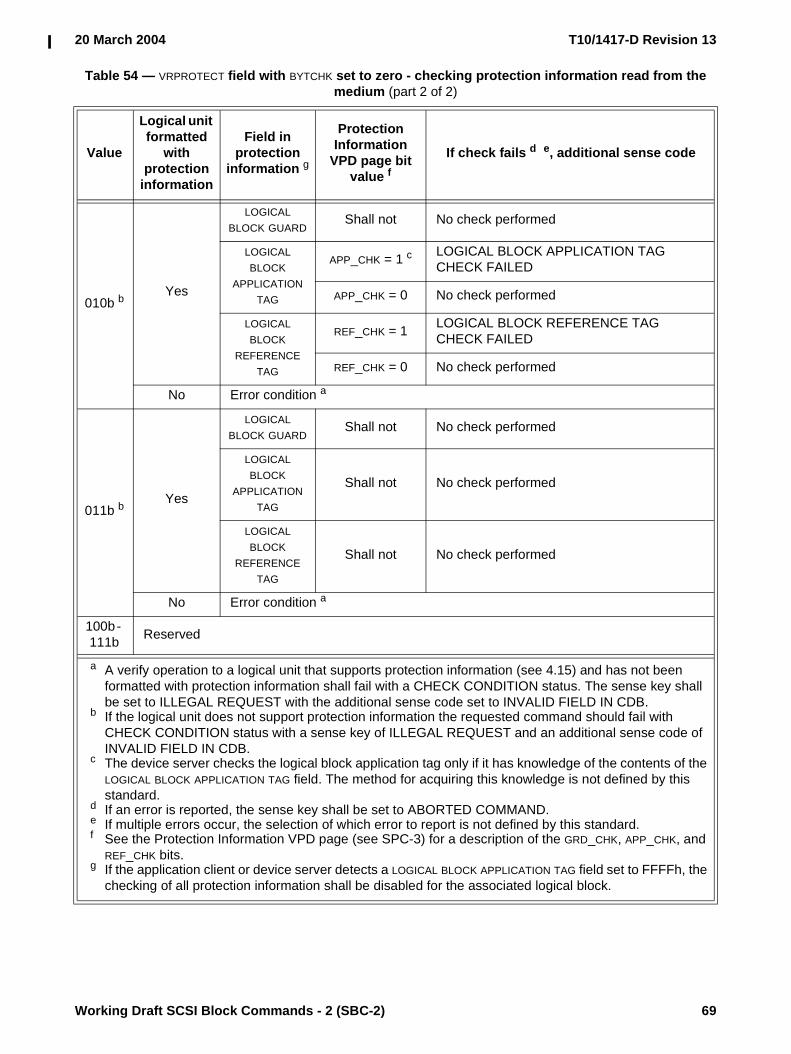
20 March 2004 T10/1417-D Revision 13
Working Draft SCSI Block Commands - 2 (SBC-2) 69
010b bYes
LOGICAL BLOCK GUARD
Shall not No check performed
LOGICAL BLOCK
APPLICATION TAG
APP_CHK = 1 c LOGICAL BLOCK APPLICATION TAG CHECK FAILED
APP_CHK = 0 No check performed
LOGICAL BLOCK
REFERENCE TAG
REF_CHK = 1 LOGICAL BLOCK REFERENCE TAG CHECK FAILED
REF_CHK = 0 No check performed
No Error condition a
011b bYes
LOGICAL BLOCK GUARD
Shall not No check performed
LOGICAL BLOCK
APPLICATION TAG
Shall not No check performed
LOGICAL BLOCK
REFERENCE TAG
Shall not No check performed
No Error condition a
100b - 111b Reserved
Table 54 — VRPROTECT field with BYTCHK set to zero - checking protection information read from the medium (part 2 of 2)
Value
Logical unit formatted
with protection
information
Field in protection
information g
Protection Information
VPD page bit value f
If check fails d e, additional sense code
a A verify operation to a logical unit that supports protection information (see 4.15) and has not been formatted with protection information shall fail with a CHECK CONDITION status. The sense key shall be set to ILLEGAL REQUEST with the additional sense code set to INVALID FIELD IN CDB.
b If the logical unit does not support protection information the requested command should fail with CHECK CONDITION status with a sense key of ILLEGAL REQUEST and an additional sense code of INVALID FIELD IN CDB.
c The device server checks the logical block application tag only if it has knowledge of the contents of the LOGICAL BLOCK APPLICATION TAG field. The method for acquiring this knowledge is not defined by this standard.
d If an error is reported, the sense key shall be set to ABORTED COMMAND.e If multiple errors occur, the selection of which error to report is not defined by this standard.f See the Protection Information VPD page (see SPC-3) for a description of the GRD_CHK, APP_CHK, and
REF_CHK bits.g If the application client or device server detects a LOGICAL BLOCK APPLICATION TAG field set to FFFFh, the
checking of all protection information shall be disabled for the associated logical block.

T10/1417-D Revision 13 20 March 2004
70 Working Draft SCSI Block Commands - 2 (SBC-2)
If the BYTCHK bit is set to one, the device server shall check the protection information read from the medium based on the VRPROTECT field as described in table 55.
Table 55 — VRPROTECT field with BYTCHK set to one - checking protection information read from the medium (part 1 of 2)
Value
Logical unit formatted
with protection
information
Field in protection
information
Protection Information
VPD page bit value f
If check fails d e, additional sense code
000bYes
LOGICAL BLOCK GUARD
GRD_CHK = 1 g LOGICAL BLOCK GUARD CHECK FAILED
GRD_CHK = 0 No check performed
LOGICAL BLOCK APPLICATION TAG
APP_CHK = 1 c g
LOGICAL BLOCK APPLICATION TAG CHECK FAILED
APP_CHK = 0 No check performed
LOGICAL BLOCK REFERENCE TAG
REF_CHK = 1 g LOGICAL BLOCK REFERENCE TAG CHECK FAILED
REF_CHK = 0 No check performed
No No protection information on the medium available to check
001b bYes
LOGICAL BLOCK GUARD
Shall not No check performed
LOGICAL BLOCK APPLICATION TAG
Shall not No check performed
LOGICAL BLOCK REFERENCE TAG
Shall not No check performed
No Error condition a
a A verify operation to a logical unit that supports protection information (see 4.15) and has not been formatted with protection information shall fail with a CHECK CONDITION status. The sense key shall be set to ILLEGAL REQUEST with the additional sense code set to INVALID FIELD IN CDB.
b If the logical unit does not support protection information the requested command should fail with CHECK CONDITION status with a sense key of ILLEGAL REQUEST and an additional sense code of INVALID FIELD IN CDB.
c The device server checks the logical block application tag only if it has knowledge of the contents of the LOGICAL BLOCK APPLICATION TAG field. The method for acquiring this knowledge is not defined by this standard.
d If an error is reported, the sense key shall be set to ABORTED COMMAND.e If multiple errors occur, the selection of which error to report is not defined by this standard.f See the Protection Information VPD page (see SPC-3) for a description of the GRD_CHK, APP_CHK, and
REF_CHK bits.g If the application client or device server detects a LOGICAL BLOCK APPLICATION TAG field set to FFFFh,
the checking of all protection information shall be disabled for the associated logical block.

20 March 2004 T10/1417-D Revision 13
Working Draft SCSI Block Commands - 2 (SBC-2) 71
010b bYes
LOGICAL BLOCK GUARD
Shall not No check performed
LOGICAL BLOCK APPLICATION TAG
Shall not No check performed
LOGICAL BLOCK REFERENCE TAG
Shall not No check performed
No Error condition a
011b bYes
LOGICAL BLOCK GUARD
Shall not No check performed
LOGICAL BLOCK APPLICATION TAG
Shall not No check performed
LOGICAL BLOCK REFERENCE TAG
Shall not No check performed
No Error condition a
100b - 111b Reserved
Table 55 — VRPROTECT field with BYTCHK set to one - checking protection information read from the medium (part 2 of 2)
Value
Logical unit formatted
with protection
information
Field in protection
information
Protection Information
VPD page bit value f
If check fails d e, additional sense code
a A verify operation to a logical unit that supports protection information (see 4.15) and has not been formatted with protection information shall fail with a CHECK CONDITION status. The sense key shall be set to ILLEGAL REQUEST with the additional sense code set to INVALID FIELD IN CDB.
b If the logical unit does not support protection information the requested command should fail with CHECK CONDITION status with a sense key of ILLEGAL REQUEST and an additional sense code of INVALID FIELD IN CDB.
c The device server checks the logical block application tag only if it has knowledge of the contents of the LOGICAL BLOCK APPLICATION TAG field. The method for acquiring this knowledge is not defined by this standard.
d If an error is reported, the sense key shall be set to ABORTED COMMAND.e If multiple errors occur, the selection of which error to report is not defined by this standard.f See the Protection Information VPD page (see SPC-3) for a description of the GRD_CHK, APP_CHK, and
REF_CHK bits.g If the application client or device server detects a LOGICAL BLOCK APPLICATION TAG field set to FFFFh,
the checking of all protection information shall be disabled for the associated logical block.

T10/1417-D Revision 13 20 March 2004
72 Working Draft SCSI Block Commands - 2 (SBC-2)
If the BYTCHK bit is set to one, the device server shall check the protection information transferred from the application client data-out buffer based on the VRPROTECT field as described in table 56.
Table 56 — VRPROTECT field with BYTCHK set to one - checking protection information from the application client
Value
Logical unit formatted
with protection
information
Field in protection
information
Device server check
If check fails d e, additional sense code
000bYes No protection information received from application client to check
No No protection information received from application client to check
001b bYes
LOGICAL BLOCK GUARD
Shall LOGICAL BLOCK GUARD CHECK FAILED
LOGICAL BLOCK APPLICATION TAG
Shall not No check performed
LOGICAL BLOCK REFERENCE TAG
Shall LOGICAL BLOCK REFERENCE TAG CHECK FAILED
No Error condition a
010b bYes
LOGICAL BLOCK GUARD
Shall not No check performed
LOGICAL BLOCK APPLICATION TAG
May c LOGICAL BLOCK APPLICATION TAG CHECK FAILED
LOGICAL BLOCK REFERENCE TAG
May LOGICAL BLOCK REFERENCE TAG CHECK FAILED
No Error condition a
011b bYes
LOGICAL BLOCK GUARD
Shall not No check performed
LOGICAL BLOCK APPLICATION TAG
Shall not No check performed
LOGICAL BLOCK REFERENCE TAG
Shall not No check performed
No Error condition a
100b - 111b Reserved
a A verify operation to a logical unit that supports protection information (see 4.15) and has not been formatted with protection information shall fail with a CHECK CONDITION status. The sense key shall be set to ILLEGAL REQUEST with the additional sense code set to INVALID FIELD IN CDB.
b If the logical unit does not support protection information the requested command should fail with CHECK CONDITION status with a sense key of ILLEGAL REQUEST and an additional sense code of INVALID FIELD IN CDB.
c The device server may check the logical block application tag if it has knowledge of the contents of the LOGICAL BLOCK APPLICATION TAG field. The method for acquiring this knowledge is not defined by this standard.
d If an error is reported, the sense key shall be set to ABORTED COMMAND.e If multiple errors occur, the selection of which error to report is not defined by this standard.
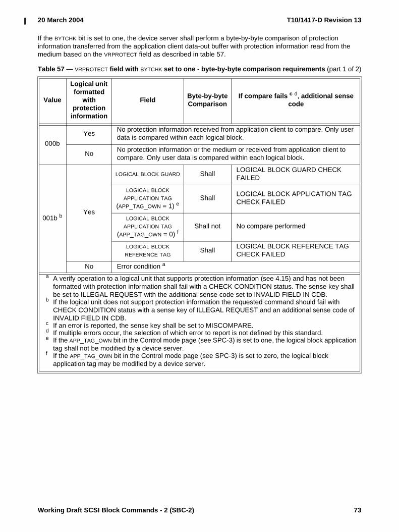
20 March 2004 T10/1417-D Revision 13
Working Draft SCSI Block Commands - 2 (SBC-2) 73
If the BYTCHK bit is set to one, the device server shall perform a byte-by-byte comparison of protection information transferred from the application client data-out buffer with protection information read from the medium based on the VRPROTECT field as described in table 57.
Table 57 — VRPROTECT field with BYTCHK set to one - byte-by-byte comparison requirements (part 1 of 2)
Value
Logical unit formatted
with protection
information
Field Byte-by-byte Comparison
If compare fails c d, additional sense code
000bYes No protection information received from application client to compare. Only user
data is compared within each logical block.
No No protection information or the medium or received from application client to compare. Only user data is compared within each logical block.
001b bYes
LOGICAL BLOCK GUARD Shall LOGICAL BLOCK GUARD CHECK FAILED
LOGICAL BLOCK APPLICATION TAG
(APP_TAG_OWN = 1) eShall LOGICAL BLOCK APPLICATION TAG
CHECK FAILED
LOGICAL BLOCK APPLICATION TAG
(APP_TAG_OWN = 0) fShall not No compare performed
LOGICAL BLOCK REFERENCE TAG
Shall LOGICAL BLOCK REFERENCE TAG CHECK FAILED
No Error condition a
a A verify operation to a logical unit that supports protection information (see 4.15) and has not been formatted with protection information shall fail with a CHECK CONDITION status. The sense key shall be set to ILLEGAL REQUEST with the additional sense code set to INVALID FIELD IN CDB.
b If the logical unit does not support protection information the requested command should fail with CHECK CONDITION status with a sense key of ILLEGAL REQUEST and an additional sense code of INVALID FIELD IN CDB.
c If an error is reported, the sense key shall be set to MISCOMPARE.d If multiple errors occur, the selection of which error to report is not defined by this standard.e If the APP_TAG_OWN bit in the Control mode page (see SPC-3) is set to one, the logical block application
tag shall not be modified by a device server.f If the APP_TAG_OWN bit in the Control mode page (see SPC-3) is set to zero, the logical block
application tag may be modified by a device server.

T10/1417-D Revision 13 20 March 2004
74 Working Draft SCSI Block Commands - 2 (SBC-2)
010b bYes
LOGICAL BLOCK GUARD Shall not No compare performed
LOGICAL BLOCK APPLICATION TAG
(APP_TAG_OWN = 1) eShall LOGICAL BLOCK APPLICATION TAG
CHECK FAILED
LOGICAL BLOCK APPLICATION TAG
(APP_TAG_OWN = 0) fShall not No compare performed
LOGICAL BLOCK REFERENCE TAG
Shall LOGICAL BLOCK REFERENCE TAG CHECK FAILED
No Error condition a
011b bYes
LOGICAL BLOCK GUARD Shall LOGICAL BLOCK GUARD CHECK FAILED
LOGICAL BLOCK APPLICATION TAG
(APP_TAG_OWN = 1) eShall LOGICAL BLOCK APPLICATION TAG
CHECK FAILED
LOGICAL BLOCK APPLICATION TAG
(APP_TAG_OWN = 0) fShall not No compare performed
LOGICAL BLOCK REFERENCE TAG
Shall LOGICAL BLOCK REFERENCE TAG CHECK FAILED
No Error condition a
100b -
111bReserved
Table 57 — VRPROTECT field with BYTCHK set to one - byte-by-byte comparison requirements (part 2 of 2)
Value
Logical unit formatted
with protection
information
Field Byte-by-byte Comparison
If compare fails c d, additional sense code
a A verify operation to a logical unit that supports protection information (see 4.15) and has not been formatted with protection information shall fail with a CHECK CONDITION status. The sense key shall be set to ILLEGAL REQUEST with the additional sense code set to INVALID FIELD IN CDB.
b If the logical unit does not support protection information the requested command should fail with CHECK CONDITION status with a sense key of ILLEGAL REQUEST and an additional sense code of INVALID FIELD IN CDB.
c If an error is reported, the sense key shall be set to MISCOMPARE.d If multiple errors occur, the selection of which error to report is not defined by this standard.e If the APP_TAG_OWN bit in the Control mode page (see SPC-3) is set to one, the logical block application
tag shall not be modified by a device server.f If the APP_TAG_OWN bit in the Control mode page (see SPC-3) is set to zero, the logical block
application tag may be modified by a device server.

20 March 2004 T10/1417-D Revision 13
Working Draft SCSI Block Commands - 2 (SBC-2) 75
5.23 VERIFY (12) commandThe VERIFY (12) command (see table 58) requests that the device server verify the data on the medium. Data includes user data and protection information, if any.
See the VERIFY (10) command (see 5.22) for a description of the fields in this command.
5.24 VERIFY (16) commandThe VERIFY (16) command (see table 59) requests that the device server verify the data written on the medium. Data includes user data and protection information, if any.
See the VERIFY (10) command (see 5.22) for a description of the fields in this command.
Table 58 — VERIFY (12) command
Byte\Bit 7 6 5 4 3 2 1 0
0 OPERATION CODE (AFh)
1 VRPROTECT DPO Reserved BLKVFY BYTCHK Obsolete
2 (MSB)LOGICAL BLOCK ADDRESS
5 (LSB)
6 (MSB)VERIFICATION LENGTH
9 (LSB)
10Restricted
for MMC-4
Reserved
11 CONTROL
Table 59 — VERIFY (16) command
Byte\Bit 7 6 5 4 3 2 1 0
0 OPERATION CODE (8Fh)
1 VRPROTECT DPO Reserved BLKVFY BYTCHK Reserved
2 (MSB)LOGICAL BLOCK ADDRESS
9 (LSB)
10 (MSB)VERIFICATION LENGTH
13 (LSB)
14 Restricted for MMC-4 Reserved
15 CONTROL

T10/1417-D Revision 13 20 March 2004
76 Working Draft SCSI Block Commands - 2 (SBC-2)
5.25 WRITE (6) commandThe WRITE (6) command (see table 60) requests that the device server write the data transferred from the application client to the medium. Data transferred from the application client includes user data but does not include protection information.
The cache control bits are not provided for this command. Block devices with cache memory may have values for the cache control bits that may affect the WRITE (6) command, however no default value is defined by this standard. If explicit control is required, the WRITE (10) command should be used.
The LOGICAL BLOCK ADDRESS field specifies the logical block where the write operation shall begin.
The TRANSFER LENGTH field specifies the number of contiguous logical blocks of data that shall be transferred. A TRANSFER LENGTH field set to zero specifies that 256 logical blocks shall be transferred. Any other value specifies the number of logical blocks that shall be transferred. If the logical block address plus the transfer length exceeds the capacity of the medium, the device server shall return CHECK CONDITION status with the sense key set to ILLEGAL REQUEST and the additional sense code set to LOGICAL BLOCK ADDRESS OUT OF RANGE. The TRANSFER LENGTH field is constrained by the MAXIMUM TRANSFER LENGTH field in the Block Limits VPD page (see 6.4.2).
NOTE 18 - For the WRITE (10) command, WRITE (12) command, and WRITE (16) command, a TRANSFER LENGTH field set to zero specifies that no logical blocks are transferred.
If a WRITE (6) command is received after protection information is enabled the device server shall set the protection information (see 4.15) as follows as it writes the logical block to the medium:
a) the LOGICAL BLOCK GUARD field to a properly generated CRC (see 4.15.3);b) the LOGICAL BLOCK REFERENCE TAG field to a properly calculated logical block reference tag (see
4.15.2); andc) the LOGICAL BLOCK APPLICATION TAG field to:
A) FFFFh if the APP_TAG_OWN bit in the Control mode page (see SPC-3) is set to one; orB) any value if the APP_TAG_OWN bit in the Control mode page (see SPC-3) is set to zero.
Table 60 — WRITE (6) command
Byte\Bit 7 6 5 4 3 2 1 0
0 OPERATION CODE (0Ah)
1 Reserved (MSB)
2 LOGICAL BLOCK ADDRESS
3 (LSB)
4 TRANSFER LENGTH
5 CONTROL

20 March 2004 T10/1417-D Revision 13
Working Draft SCSI Block Commands - 2 (SBC-2) 77
5.26 WRITE (10) commandThe WRITE (10) command (see table 61) requests that the device server write the data transferred from the application client to the medium. Data transferred from the application client includes user data and includes protection information as required by the WRPROTECT field and the medium format.
See the READ (10) command (see 5.9) for a definition of the DPO bit and the FUA bit. See the LOCK UNLOCK CACHE (10) command (see 5.4) for a definition of the LOGICAL BLOCK ADDRESS field.
The TRANSFER LENGTH field specifies the number of contiguous logical blocks of data that shall be transferred. A TRANSFER LENGTH field set to zero specifies that no logical blocks shall be transferred. This condition shall not be considered an error and no data shall be written. Any other value specifies the number of logical blocks that shall be transferred. If the logical block address plus the transfer length exceeds the capacity of the medium, the device server shall return CHECK CONDITION status with the sense key set to ILLEGAL REQUEST and the additional sense code set to LOGICAL BLOCK ADDRESS OUT OF RANGE. The TRANSFER LENGTH field is constrained by the MAXIMUM TRANSFER LENGTH field in the Block Limits VPD page (see 6.4.2).
NOTE 19 - For the WRITE (6) command, a TRANSFER LENGTH field set to zero specifies that 256 logical blocks are transferred.
Table 61 — WRITE (10) command
Byte\Bit 7 6 5 4 3 2 1 0
0 OPERATION CODE (2Ah)
1 WRPROTECT DPO FUA Reserved Obsolete
2 (MSB)LOGICAL BLOCK ADDRESS
5 (LSB)
6 Reserved
7 (MSB)TRANSFER LENGTH
8 (LSB)
9 CONTROL

T10/1417-D Revision 13 20 March 2004
78 Working Draft SCSI Block Commands - 2 (SBC-2)
The device server shall check the protection information transferred from the application client data-out buffer based on the WRPROTECT field as described in table 62.
Table 62 — WRPROTECT field (part 1 of 2)
Value
Logical unit formatted
with protection
information
Field in protection
information
Device server check
If check fails d g, additional sense code
000bYes f No protection information received from application client to check
No No protection information received from application client to check
001b bYes e
LOGICAL BLOCK GUARD
Shall LOGICAL BLOCK GUARD CHECK FAILED
LOGICAL BLOCK APPLICATION TAG
Shall not No check performed
LOGICAL BLOCK REFERENCE TAG
Shall LOGICAL BLOCK REFERENCE TAG CHECK FAILED
No a No protection information available to check
a A write operation to a logical unit that supports protection information (see 4.15) and has not been formatted with protection information shall fail with a CHECK CONDITION status. The sense key shall be set to ILLEGAL REQUEST with the additional sense code set to INVALID FIELD IN CDB.
b If the logical unit does not support protection information the requested command should fail with CHECK CONDITION status with a sense key of ILLEGAL REQUEST and an additional sense code of INVALID FIELD IN CDB.
c The device server may check the logical block application tag if it has knowledge of the contents of the LOGICAL BLOCK APPLICATION TAG field. The method for acquiring this knowledge is not defined by this standard.
d If an error is reported the sense key shall be set to ABORTED COMMAND.e Device server shall preserve the contents of protection information (e.g., write to medium, store in
non-volatile memory).f The device server shall write a properly generated CRC (see 4.15.3.2) into the LOGICAL BLOCK GUARD
field, a properly calculated logical block reference tag into the LOGICAL BLOCK REFERENCE TAG field (see 4.15.2), and if the APP_TAG_OWN bit in the Control mode page (see SPC-3) is set to one, FFFFh into the LOGICAL BLOCK APPLICATION TAG field as it writes the logical block to the medium. If the APP_TAG_OWN bit is set to zero, the device server may set the LOGICAL BLOCK APPLICATION TAG field to any value.
g If multiple errors occur, the selection of which error to report is not defined by this standard.

20 March 2004 T10/1417-D Revision 13
Working Draft SCSI Block Commands - 2 (SBC-2) 79
Editor’s Note 12: should there be a “Include?” column in this table to clarify when the application client is expected to include protection information in the application client data buffer?
010b bYes e
LOGICAL BLOCK GUARD
Shall not No check performed
LOGICAL BLOCK APPLICATION TAG
May c LOGICAL BLOCK APPLICATION TAG CHECK FAILED
LOGICAL BLOCK REFERENCE TAG
May LOGICAL BLOCK REFERENCE TAG CHECK FAILED
No a No protection information available to check
011b bYes e
LOGICAL BLOCK GUARD
Shall not No check performed
LOGICAL BLOCK APPLICATION TAG
Shall not No check performed
LOGICAL BLOCK REFERENCE TAG
Shall not No check performed
No a No protection information available to check
100b - 111b Reserved
Table 62 — WRPROTECT field (part 2 of 2)
Value
Logical unit formatted
with protection
information
Field in protection
information
Device server check
If check fails d g, additional sense code
a A write operation to a logical unit that supports protection information (see 4.15) and has not been formatted with protection information shall fail with a CHECK CONDITION status. The sense key shall be set to ILLEGAL REQUEST with the additional sense code set to INVALID FIELD IN CDB.
b If the logical unit does not support protection information the requested command should fail with CHECK CONDITION status with a sense key of ILLEGAL REQUEST and an additional sense code of INVALID FIELD IN CDB.
c The device server may check the logical block application tag if it has knowledge of the contents of the LOGICAL BLOCK APPLICATION TAG field. The method for acquiring this knowledge is not defined by this standard.
d If an error is reported the sense key shall be set to ABORTED COMMAND.e Device server shall preserve the contents of protection information (e.g., write to medium, store in
non-volatile memory).f The device server shall write a properly generated CRC (see 4.15.3.2) into the LOGICAL BLOCK GUARD
field, a properly calculated logical block reference tag into the LOGICAL BLOCK REFERENCE TAG field (see 4.15.2), and if the APP_TAG_OWN bit in the Control mode page (see SPC-3) is set to one, FFFFh into the LOGICAL BLOCK APPLICATION TAG field as it writes the logical block to the medium. If the APP_TAG_OWN bit is set to zero, the device server may set the LOGICAL BLOCK APPLICATION TAG field to any value.
g If multiple errors occur, the selection of which error to report is not defined by this standard.

T10/1417-D Revision 13 20 March 2004
80 Working Draft SCSI Block Commands - 2 (SBC-2)
5.27 WRITE (12) commandThe WRITE (12) command (see table 63) requests that the device server write the data transferred from the application client to the medium. Data transferred from the application client includes user data and includes protection information as required by the WRPROTECT field and the medium format.
See the WRITE (10) command (see 5.26) for a description of the fields in this command.
5.28 WRITE (16) commandThe WRITE (16) command (see table 64) requests that the device server write the data transferred from the application client to the medium. Data transferred from the application client includes user data and includes protection information as required by the WRPROTECT field and the medium format.
See the WRITE (10) command (see 5.26) for a description of the fields in this command.
5.29 WRITE AND VERIFY (10) commandThe WRITE AND VERIFY (10) command (see table 65) requests that the device server write the data transferred from the application client to the medium and then verify that the data is correctly written. Data transferred from the application client includes user data and includes protection information as required by
Table 63 — WRITE (12) command
Byte\Bit 7 6 5 4 3 2 1 0
0 OPERATION CODE (AAh)
1 WRPROTECT DPO FUA Reserved Obsolete
2 (MSB)LOGICAL BLOCK ADDRESS
5 (LSB)
6 (MSB)TRANSFER LENGTH
9 (LSB)
10 Restricted for MMC-4 Reserved
11 CONTROL
Table 64 — WRITE (16) command
Byte\Bit 7 6 5 4 3 2 1 0
0 OPERATION CODE (8Ah)
1 WRPROTECT DPO FUA Reserved Reserved
2 (MSB)LOGICAL BLOCK ADDRESS
9 (LSB)
10 (MSB)TRANSFER LENGTH
13 (LSB)
14 Restricted for MMC-4 Reserved
15 CONTROL

20 March 2004 T10/1417-D Revision 13
Working Draft SCSI Block Commands - 2 (SBC-2) 81
the WRPROTECT field and the medium format. The data is only transferred once from the application client to the device server.
See the LOCK UNLOCK CACHE (10) command (see 5.4) for a definition of the LOGICAL BLOCK ADDRESS field. See the WRITE (10) command (see 5.26) for a definition of the TRANSFER LENGTH field and the WRPROTECT field. See the READ (10) command (see 5.9) for a description of the DPO bit.
If the MODE SELECT command is implemented, and the Verify Error Recovery mode page (see 6.3.5) is also implemented, then the current settings in that mode page along with the AWRE bit in the Read-Write Error Recovery mode page (see 6.3.4) specify the verification error criteria. If these mode pages are not implemented, then the verification criteria is vendor-specific.
A byte check (BYTCHK) bit set to zero specifies that the device server perform a medium verification with no data comparison. A BYTCHK bit set to one specifies that the device server perform a byte-by-byte comparison of data written on the medium with the data transferred from the application client data-out buffer. If the comparison is unsuccessful for any reason, the device server shall return CHECK CONDITION status with the sense key set to MISCOMPARE with the appropriate additional sense code for the condition.
5.30 WRITE AND VERIFY (12) commandThe WRITE AND VERIFY (12) command (see table 66) requests that the device server write the data transferred from the application client to the medium and then verify that the data is correctly written. Data includes user data and protection information, if any.
See the WRITE AND VERIFY (10) command (see 5.29) for a description of the bits in this command.
Table 65 — WRITE AND VERIFY (10) command
Byte\Bit 7 6 5 4 3 2 1 0
0 OPERATION CODE (2Eh)
1 WRPROTECT DPO Reserved BYTCHK Obsolete
2 (MSB)LOGICAL BLOCK ADDRESS
5 (LSB)
6 Reserved
7 (MSB)TRANSFER LENGTH
8 (LSB)
9 CONTROL
Table 66 — WRITE AND VERIFY (12) command
Byte\Bit 7 6 5 4 3 2 1 0
0 OPERATION CODE (AEh)
1 WRPROTECT DPO Reserved BYTCHK Obsolete
2 (MSB)LOGICAL BLOCK ADDRESS
5 (LSB)
6 (MSB)TRANSFER LENGTH
9 (LSB)
10 Restricted for MMC-4 Reserved
11 CONTROL

T10/1417-D Revision 13 20 March 2004
82 Working Draft SCSI Block Commands - 2 (SBC-2)
5.31 WRITE AND VERIFY (16) commandThe WRITE AND VERIFY (16) command (see table 67) requests that the device server write the data transferred from the application client to the medium and then verify that the data is correctly written. Data transferred from the application client includes user data and includes protection information as required by the WRPROTECT field and the medium format. The data is only transferred once from the application client to the device server.
See the WRITE AND VERIFY (10) command (see 5.29) for a description of the fields in this command.
5.32 WRITE LONG (10) commandThe WRITE LONG (10) command (see table 68) requests that the device server write the data transferred from the application client to one logical block on the medium. The data written is implementation specific, but shall include the data bytes, any protection information, and any additional information (e.g., ECC bytes).
See the LOCK UNLOCK CACHE (10) command (see 5.4) for a definition of the LOGICAL BLOCK ADDRESS field.
NOTE 20 - Any other bytes that can be corrected by ECC should be included (e.g., a data synchronization mark within the area covered by ECC). A READ LONG command may be issued before issuing a WRITE LONG command. The WRITE LONG data should be the same length and in the same order as the data returned by the READ LONG command.
The BYTE TRANSFER LENGTH field specifies the number of bytes of data that the device server shall transfer to the specified logical block. If the BYTE TRANSFER LENGTH field is not set to zero and does not exactly match the
Table 67 — WRITE AND VERIFY (16) command
Byte\Bit 7 6 5 4 3 2 1 0
0 OPERATION CODE (8Eh)
1 Reserved DPO Reserved BYTCHK Reserved
2 (MSB)LOGICAL BLOCK ADDRESS
9 (LSB)
10 (MSB)TRANSFER LENGTH
13 (LSB)
14 Restricted for MMC-4 Reserved
15 CONTROL
Table 68 — WRITE LONG (10) command
Byte\Bit 7 6 5 4 3 2 1 0
0 OPERATION CODE (3Fh)
1 Reserved Obsolete
2 (MSB)LOGICAL BLOCK ADDRESS
5 (LSB)
6 Reserved
7 (MSB)BYTE TRANSFER LENGTH
8 (LSB)
9 CONTROL

20 March 2004 T10/1417-D Revision 13
Working Draft SCSI Block Commands - 2 (SBC-2) 83
data length the device server returns for a READ LONG command, then the device server shall terminate the command with CHECK CONDITION status with the sense key set to ILLEGAL REQUEST and the additional sense code set to INVALID FIELD IN CDB. In the sense data (see SPC-3), the ILI and VALID bits shall be set to one and the INFORMATION field shall be set to the difference (i.e., residue) of the requested length minus the actual length in bytes. Negative values shall be indicated by two's complement notation. A BYTE TRANSFER LENGTH field set to zero specifies that no bytes shall be transferred. This condition shall not be considered an error.
5.33 WRITE LONG (16) commandThe WRITE LONG (16) command (see table 69) requests that the device server write the data transferred from the application client to one logical block on the medium. The data written is implementation specific, but shall include the data bytes, any protection information, and any additional information (e.g., ECC bytes). This command is implemented as a service action of the SERVICE ACTION OUT opcode.
See the WRITE LONG (10) command (see 5.32) for a description of the fields in this command.
5.34 WRITE SAME (10) commandThe WRITE SAME (10) command (see table 70) requests that the device server write the single block of data transferred from the application client to the medium multiple times to consecutive multiple logical blocks. Data transferred from the application client includes user data and includes protection information as required by the WRPROTECT field and the medium format.
Table 69 — WRITE LONG (16) command
Byte\Bit 7 6 5 4 3 2 1 0
0 OPERATION CODE (9Fh)
1 Reserved SERVICE ACTION (11h)
2 (MSB)LOGICAL BLOCK ADDRESS
9 (LSB)
10Reserved
11
12 (MSB)BYTE TRANSFER LENGTH
13 (LSB)
14 Reserved CORRCT
15 CONTROL

T10/1417-D Revision 13 20 March 2004
84 Working Draft SCSI Block Commands - 2 (SBC-2)
NOTE 21 - This command may be useful if large areas of the medium need to be written, prepared for certifi-cation, or otherwise initialized without the application client having to transfer all the data.
See the LOCK UNLOCK CACHE (10) command (see 5.4) for a definition of the LOGICAL BLOCK ADDRESS field.
If the medium is formatted with protection information the value in the LOGICAL BLOCK REFERENCE TAG field received from the application client shall be placed into the LOGICAL BLOCK REFERENCE TAG field (see 4.5.2) of the first logical block written to the medium. Into each of the following logical blocks the logical block reference tag received in the data transferred from the application client, incremented by one, shall be placed into the LOGICAL BLOCK REFERENCE TAG field of that logical block (i.e., each logical block written to the medium has a logical block reference tag value of one greater than the previous logical block).
If the APP_TAG_OWN bit in the Control mode page (see SPC-3) is set to one, the logical block application tag received in the single block of data shall be placed in the LOGICAL BLOCK APPLICATION TAG field of each logical block. If the APP_TAG_OWN bit is set to zero, the logical block application tag received in the single block of data may be placed in the LOGICAL BLOCK APPLICATION TAG field of each logical block.
Table 70 — WRITE SAME (10) command
Byte\Bit 7 6 5 4 3 2 1 0
0 OPERATION CODE (41h)
1 WRPROTECT Reserved PBDATA LBDATA Obsolete
2 (MSB)LOGICAL BLOCK ADDRESS
5 (LSB)
6 Reserved
7 (MSB)NUMBER OF BLOCKS
8 (LSB)
9 CONTROL
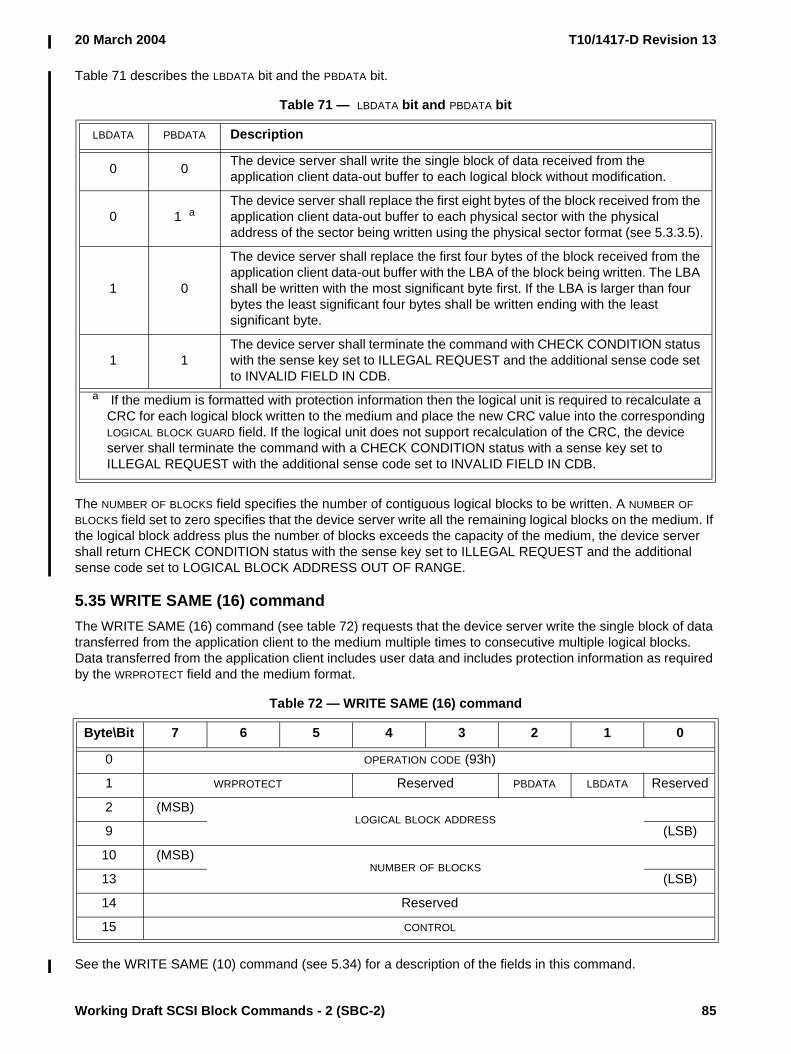
20 March 2004 T10/1417-D Revision 13
Working Draft SCSI Block Commands - 2 (SBC-2) 85
Table 71 describes the LBDATA bit and the PBDATA bit.
The NUMBER OF BLOCKS field specifies the number of contiguous logical blocks to be written. A NUMBER OF BLOCKS field set to zero specifies that the device server write all the remaining logical blocks on the medium. If the logical block address plus the number of blocks exceeds the capacity of the medium, the device server shall return CHECK CONDITION status with the sense key set to ILLEGAL REQUEST and the additional sense code set to LOGICAL BLOCK ADDRESS OUT OF RANGE.
5.35 WRITE SAME (16) commandThe WRITE SAME (16) command (see table 72) requests that the device server write the single block of data transferred from the application client to the medium multiple times to consecutive multiple logical blocks. Data transferred from the application client includes user data and includes protection information as required by the WRPROTECT field and the medium format.
See the WRITE SAME (10) command (see 5.34) for a description of the fields in this command.
Table 71 — LBDATA bit and PBDATA bit
LBDATA PBDATA Description
0 0 The device server shall write the single block of data received from the application client data-out buffer to each logical block without modification.
0 1 aThe device server shall replace the first eight bytes of the block received from the application client data-out buffer to each physical sector with the physical address of the sector being written using the physical sector format (see 5.3.3.5).
1 0
The device server shall replace the first four bytes of the block received from the application client data-out buffer with the LBA of the block being written. The LBA shall be written with the most significant byte first. If the LBA is larger than four bytes the least significant four bytes shall be written ending with the least significant byte.
1 1The device server shall terminate the command with CHECK CONDITION status with the sense key set to ILLEGAL REQUEST and the additional sense code set to INVALID FIELD IN CDB.
a If the medium is formatted with protection information then the logical unit is required to recalculate a CRC for each logical block written to the medium and place the new CRC value into the corresponding LOGICAL BLOCK GUARD field. If the logical unit does not support recalculation of the CRC, the device server shall terminate the command with a CHECK CONDITION status with a sense key set to ILLEGAL REQUEST with the additional sense code set to INVALID FIELD IN CDB.
Table 72 — WRITE SAME (16) command
Byte\Bit 7 6 5 4 3 2 1 0
0 OPERATION CODE (93h)
1 WRPROTECT Reserved PBDATA LBDATA Reserved
2 (MSB)LOGICAL BLOCK ADDRESS
9 (LSB)
10 (MSB)NUMBER OF BLOCKS
13 (LSB)
14 Reserved
15 CONTROL

T10/1417-D Revision 13 20 March 2004
86 Working Draft SCSI Block Commands - 2 (SBC-2)
5.36 XDREAD (10) commandThe XDREAD (10) command (see table 73) requests that the target transfer to the initiator the XOR data generated by an XDWRITE command. Data transferred from the device server includes user data and includes protection information as required by the XORPINFO bit and the medium format.
If the XOR protection information (XORPINFO) bit is set to zero, the device server shall not check or transmit protection information. If the XORPINFO bit is set to one, the device server supports protection information, and the medium has been formatted with protection information, the device server shall transmit protection information but shall not check any of the fields. If the XORPINFO bit is set to one, the device server supports protection information, and the medium has not been formatted with protection information, the device server shall terminate the command with CHECK CONDITION status with a sense key of ILLEGAL REQUEST and an additional sense code of INVALID FIELD IN CDB. If the XORPINFO bit is set to one and the device server does not support protection information, the device server should terminate the command with CHECK CONDITION status with a sense key of ILLEGAL REQUEST and an additional sense code of INVALID FIELD IN CDB.
The XOR data transferred is identified by the LOGICAL BLOCK ADDRESS field and the TRANSFER LENGTH field. The LOGICAL BLOCK ADDRESS field and TRANSFER LENGTH field shall be the same as, or a subset of, those specified in a prior XDWRITE command. If a match is not found the command is terminated with a CHECK CONDITION status with the sense key set to ILLEGAL REQUEST and the additional sense code set to INVALID FIELD IN CDB. The TRANSFER LENGTH field is constrained by the MAXIMUM TRANSFER LENGTH field in the Block Limits VPD page (see 6.4.2).
Table 73 — XDREAD (10) command
Byte\Bit 7 6 5 4 3 2 1 0
0 OPERATION CODE (52h)
1 Reserved XORPINFO
2 (MSB)LOGICAL BLOCK ADDRESS
5 (LSB)
6 Reserved
7 (MSB)TRANSFER LENGTH
8 (LSB)
9 CONTROL

20 March 2004 T10/1417-D Revision 13
Working Draft SCSI Block Commands - 2 (SBC-2) 87
5.37 XDREAD (32) commandThe XDREAD (32) command (see table 74) requests that the target transfer to the initiator the XOR data generated by an XDWRITE command. Data transferred from the device server includes user data and includes protection information as required by the XORPINFO bit and the medium format.
See the XDREAD (10) command (see 5.36) and SPC-3 for a description of the fields in this command.
5.38 XDWRITE (10) commandThe XDWRITE (10) command (see table 75) requests that the target XOR the data transferred from the application client with the data on the medium. Data transferred from the application client includes user data and includes protection information as required by the WRPROTECT field and the medium format. The resulting XOR data is stored by the target until it is retrieved by an XDREAD (10) command.
Table 74 — XDREAD (32) command
Byte\Bit 7 6 5 4 3 2 1 0
0 OPERATION CODE (7Fh)
1 CONTROL
2Reserved
6
7 ADDITIONAL CDB LENGTH (18h)
8 (MSB)SERVICE ACTION (0003h)
9 (LSB)
10 Reserved XORPINFO
11 Reserved
12 (MSB)LOGICAL BLOCK ADDRESS
19 (LSB)
20Reserved
27
28 (MSB)TRANSFER LENGTH
31 (LSB)
Table 75 — XDWRITE (10) command
Byte\Bit 7 6 5 4 3 2 1 0
0 OPERATION CODE (50h)
1 WRPROTECT DPO FUADISABLE WRITE
Reserved
2 (MSB)LOGICAL BLOCK ADDRESS
5 (LSB)
6 Reserved
7 (MSB)TRANSFER LENGTH
8 (LSB)
9 CONTROL

T10/1417-D Revision 13 20 March 2004
88 Working Draft SCSI Block Commands - 2 (SBC-2)
See the READ (10) command (see 5.9) for a definition of the DPO bit and the FUA bit. See the WRITE (10) command (see 5.26) for a definition of the WRPROTECT field.
A DISABLE WRITE bit set to zero specifies that the data transferred from the application client shall be written to the medium after the XOR operation is complete. A DISABLE WRITE bit set to one specifies that the data shall not be written to the medium.
The LOGICAL BLOCK ADDRESS field specifies the starting LBA of the data on which an XOR operation shall be performed with the data from the medium.
The TRANSFER LENGTH field specifies the number of logical blocks that shall be transferred from the application client and the number of logical blocks on which an XOR operation shall be performed with the data from the medium. If the logical block address plus the transfer length exceeds the capacity of the medium, the device server shall return CHECK CONDITION status with the sense key set to ILLEGAL REQUEST and the additional sense code set to LOGICAL BLOCK ADDRESS OUT OF RANGE. The TRANSFER LENGTH field is constrained by the MAXIMUM TRANSFER LENGTH field in the Block Limits VPD page (see 6.4.2).
The resulting XOR data is retrieved by an XDREAD command with starting LOGICAL BLOCK ADDRESS field and TRANSFER LENGTH field that match, or are a subset of, the starting LOGICAL BLOCK ADDRESS field and TRANSFER LENGTH field of this command.
5.39 XDWRITE (32) commandThe XDWRITE (32) command (see table 76) requests that the target XOR the data transferred from the application client with the data on the medium. Data transferred from the application client includes user data and includes protection information as required by the WRPROTECT field and the medium format. The resulting XOR data is stored by the target until it is retrieved by an XDREAD (32) command.
See the XDWRITE (10) command (see 5.38) and SPC-3 for a description of the fields in this command.
Table 76 — XDWRITE (32) command
Byte\Bit 7 6 5 4 3 2 1 0
0 OPERATION CODE (7Fh)
1 CONTROL
2Reserved
6
7 ADDITIONAL CDB LENGTH (18h)
8 (MSB)SERVICE ACTION (0004h)
9 (LSB)
10 WRPROTECT DPO FUADISABLE WRITE
Reserved
11 Reserved
12 (MSB)LOGICAL BLOCK ADDRESS
19 (LSB)
20Reserved
27
28 (MSB)TRANSFER LENGTH
31 (LSB)

20 March 2004 T10/1417-D Revision 13
Working Draft SCSI Block Commands - 2 (SBC-2) 89
5.40 XDWRITEREAD (10) commandThe XDWRITEREAD (10) command (see table 77) requests that the target XOR the data transferred from the application client with the data on the medium and return the resulting XOR data to the application client. Data transferred to and from the application client includes user data and includes protection information as required by the WRPROTECT field, the XORPINFO bit, and the medium format. This is the equivalent to an XDWRITE (10) followed by an XDREAD (10) with the same LBA and transfer length. This command is only available on transport protocols supporting bidirectional commands.
See the XDWRITE (10) command (see 5.38) and XDREAD (10) command (see 5.36) for a description of the fields in this command.
5.41 XDWRITEREAD (32) commandThe XDWRITEREAD (32) command (see table 78) requests that the target XOR the data transferred from the application client with the data on the medium and return the resulting XOR data to the application client. Data transferred to and from the application client includes user data and includes protection information as required by the WRPROTECT field, the XORPINFO bit, and the medium format. This is the equivalent to an
Table 77 — XDWRITEREAD (10) command
Byte\Bit 7 6 5 4 3 2 1 0
0 OPERATION CODE (53h)
1 WRPROTECT DPO FUADISABLE WRITE
Reserved XORPINFO
2 (MSB)LOGICAL BLOCK ADDRESS
5 (LSB)
6 Reserved
7 (MSB)TRANSFER LENGTH
8 (LSB)
9 CONTROL

T10/1417-D Revision 13 20 March 2004
90 Working Draft SCSI Block Commands - 2 (SBC-2)
XDWRITE (32) followed by an XDREAD (32) with the same LBA and transfer length. This command is only available on transport protocols supporting bidirectional commands.
See the XDWRITEREAD (10) command (see 5.40) and SPC-3 for a description of the fields in this command.
5.42 XPWRITE (10) commandThe XPWRITE (10) command (see table 79) requests that the target XOR the data transferred from the application client with the data on the medium and then write the XOR data to the medium. Data transferred from the device server includes user data and includes protection information as required by the XORPINFO bit and the medium format.
See the READ (10) command (see 5.9) for a definition of the DPO bit and the FUA bit.
Table 78 — XDWRITEREAD (32) command
Byte\Bit 7 6 5 4 3 2 1 0
0 OPERATION CODE (7Fh)
1 CONTROL
2Reserved
6
7 ADDITIONAL CDB LENGTH (18h)
8 (MSB)SERVICE ACTION (0007h)
9 (LSB)
10 WRPROTECT DPO FUADISABLE WRITE
Reserved XORPINFO
11 Reserved
12 (MSB)LOGICAL BLOCK ADDRESS
19 (LSB)
20Reserved
27
28 (MSB)TRANSFER LENGTH
31 (LSB)
Table 79 — XPWRITE (10) command
Byte\Bit 7 6 5 4 3 2 1 0
0 OPERATION CODE (51h)
1 Reserved DPO FUA Reserved XORPINFO
2 (MSB)LOGICAL BLOCK ADDRESS
5 (LSB)
6 Reserved
7 (MSB)TRANSFER LENGTH
8 (LSB)
9 CONTROL
20 March 2004 T10/1417-D Revision 13
Working Draft SCSI Block Commands - 2 (SBC-2) 91
If the XOR protection information (XORPINFO) bit is set to zero, the device server supports protection information, and the medium has been formatted with protection information, the device server shall terminate the command with CHECK CONDITION status with a sense key of ILLEGAL REQUEST and an additional sense code of INVALID FIELD IN CDB.
If the XORPINFO bit is set to one, the device server supports protection information, and the medium has been formatted with protection information, the device server shall XOR the data and protection information transferred from the application client with the data and protection information on the medium and then write the XOR result to the medium. The device server shall not check any of the fields.
If the XORPINFO bit is set to one, the device server supports protection information, and the medium has not been formatted with protection information, the device server shall terminate the command with CHECK CONDITION status with a sense key of ILLEGAL REQUEST and an additional sense code of INVALID FIELD IN CDB.
If the XORPINFO bit is set to one and the device server does not support protection information, the device server should terminate the command with CHECK CONDITION status with a sense key of ILLEGAL REQUEST and an additional sense code of INVALID FIELD IN CDB.
The LOGICAL BLOCK ADDRESS field specifies the starting LBA where the target shall read data from its medium. It also specifies the starting LBA where the XOR result data shall be written to the medium.
The TRANSFER LENGTH field specifies the number of logical blocks that shall be read from the medium. It also specifies the number of logical blocks that shall be written to the medium. If the logical block address plus the transfer length exceeds the capacity of the medium, the device server shall return CHECK CONDITION statuswith the sense key set to ILLEGAL REQUEST and the additional sense code set to LOGICAL BLOCK ADDRESS OUT OF RANGE. The TRANSFER LENGTH field is constrained by the MAXIMUM TRANSFER LENGTH field in the Block Limits VPD page (see 6.4.2).
Editor’s Note 13: Why is there no WRPROTECT field to protect the application client to device server data being transferred?
5.43 XPWRITE (32) commandThe XPWRITE (32) command (see table 80) requests that the target XOR the data transferred from the application client with the data on the medium and then write the XOR data to the medium. Data transferred

T10/1417-D Revision 13 20 March 2004
92 Working Draft SCSI Block Commands - 2 (SBC-2)
from the device server includes user data and includes protection information as required by the XORPINFO bit and the medium format.
See the XPWRITE (10) command (see 5.42) and SPC-3 for a description of the fields in this command.
Editor’s Note 14: Why is there no WRPROTECT field to protect the application client to device server data being transferred?
Table 80 — XPWRITE (32) command
Byte\Bit 7 6 5 4 3 2 1 0
0 OPERATION CODE (7Fh)
1 CONTROL
2Reserved
6
7 ADDITIONAL CDB LENGTH (18h)
8 (MSB)SERVICE ACTION (0006h)
9 (LSB)
10 Reserved DPO FUA Reserved XORPINFO
11 Reserved
12 (MSB)LOGICAL BLOCK ADDRESS
19 (LSB)
20Reserved
27
28 (MSB)TRANSFER LENGTH
31 (LSB)

20 March 2004 T10/1417-D Revision 13
Working Draft SCSI Block Commands - 2 (SBC-2) 93
6 Parameters for direct-access block devices
6.1 Diagnostic parameters
6.1.1 Diagnostic parameters overview
This subclause defines the descriptors and pages for diagnostic parameters used with direct-access devices. The diagnostic page codes for direct-access devices are defined in table 81.
6.1.2 Translate Address Output diagnostic page
The Translate Address diagnostic pages allow the application client to translate an address in one of the forms supported by the FORMAT UNIT command (see 5.3) - a block address, a physical sector address, or a physical bytes from index address - into any one of the other formats. The address to be translated is passed to the device server with the SEND DIAGNOSTIC command and the results are returned to the application client by the RECEIVE DIAGNOSTIC RESULTS command. The format of the Translate Address Output diagnostic page sent with SEND DIAGNOSTIC is shown in table 82. The translated address is returned in the Translate Address Input diagnostic page (see table 83).
The SUPPLIED FORMAT field specifies the format of ADDRESS TO TRANSLATE field. Valid values for this field are defined in the DEFECT LIST FORMAT field of the FORMAT UNIT command (see 5.3). If the device server does not support the requested format it shall terminate the SEND DIAGNOSTIC command with CHECK
Table 81 — Diagnostic page codes
Diagnostic page code Description Reference
00h Supported diagnostic pages SPC-3
01h - 1Fh SCSI enclosure services diagnostic pages SES-2
20h - 3Fh Diagnostic pages assigned by SPC-3 SPC-3
40h Translate Address Output diagnostic page 6.1.2
40h Translate Address Input diagnostic page 6.1.3
41h Device Status Output diagnostic page 6.1.4
41h Device Status Input diagnostic page 6.1.5
42h - 7Fh Reserved for this standard
80h - FFh Vendor-specific diagnostic pages
Table 82 — Translate Address Output diagnostic page
Byte\Bit 7 6 5 4 3 2 1 0
0 PAGE CODE (40h)
1 Reserved
2 (MSB)PAGE LENGTH (000Ah)
3 (LSB)
4 Reserved SUPPLIED FORMAT
5 Reserved TRANSLATE FORMAT
6 (MSB)ADDRESS TO TRANSLATE
13 (LSB)

T10/1417-D Revision 13 20 March 2004
94 Working Draft SCSI Block Commands - 2 (SBC-2)
CONDITION status. The sense key shall be set to ILLEGAL REQUEST and the additional sense code shall be set to INVALID FIELD IN PARAMETER LIST.
The TRANSLATE FORMAT field specifies the format the device server shall use for the result of the address translation. Valid values for this field are defined in the DEFECT LIST FORMAT field of the FORMAT UNIT command. If the device server does not support the specified format it shall terminate the command with CHECK CONDITION status, with a sense key set to ILLEGAL REQUEST and an additional sense code set to INVALID FIELD IN PARAMETER LIST.
The ADDRESS TO TRANSLATE field contains a single address the application client is requesting the device server to translate. The format of this field depends on the value in the SUPPLIED FORMAT field. The formats are described in 5.3.3. If the short block format defect descriptor is specified, the block address shall be in the first four bytes of ADDRESS TO TRANSLATE field field with the remaining bytes set to zero.
6.1.3 Translate Address Input diagnostic page
Table 83 defines the Translate Address Input diagnostic page retrieved with RECEIVE DIAGNOSTIC RESULTS after the Translate Address Output diagnostic page has been sent with SEND DIAGNOSTIC.
The Translate Address diagnostic page contains a four-byte page header that specifies the page code and length followed by two bytes that describe the translated address followed by zero or more translated address(s).
The PAGE LENGTH field contains the number of parameter bytes that follow.
The SUPPLIED FORMAT field contains the value from the SEND DIAGNOSTIC command SUPPLIED FORMAT field (see 6.1.2).
A reserved area (RAREA) bit set to zero indicates that no part of the translated address falls within a reserved area of the medium. A RAREA bit set to one indicates that all or part of the translated address falls within a reserved area of the medium (e.g., speed tolerance gap, alternate sector, vendor reserved area, etc.). If the entire translated address falls within a reserved area, the device server may not return a translated address.
An alternate sector (ALTSEC) bit set to zero indicates that no part of the translated address is located in an alternate sector of the medium or that the device server is unable to determine this information. An ALTSEC bit set to one indicates that the translated address is physically located in an alternate sector of the medium. If the device server is unable to determine if all or part of the translated address is located in an alternate sector it shall set this bit to zero.
Table 83 — Translate Address Input diagnostic page
Byte\Bit 7 6 5 4 3 2 1 0
0 PAGE CODE (40h)
1 Reserved
2 (MSB)PAGE LENGTH
3 (LSB)
4 Reserved SUPPLIED FORMAT
5 RAREA ALTSEC ALTTRK Reserved TRANSLATED FORMAT
Translated address(es)
6 (MSB)TRANSLATED ADDRESS 1
13 (LSB)
…
n - 7 (MSB)TRANSLATED ADDRESS x (if required)
n (LSB)

20 March 2004 T10/1417-D Revision 13
Working Draft SCSI Block Commands - 2 (SBC-2) 95
An alternate track (ALTTRK) bit set to zero indicates that no part of the translated address is located on an alternate track of the medium. An ALTTRK bit set to one indicates that part or all of the translated address is located on an alternate track of the medium or the device server is unable to determine if all or part of the translated address is located on an alternate track.
The TRANSLATED FORMAT field contains the value from the Translate Address Output diagnostic page’s TRANSLATE FORMAT field (see 6.1.2).
The TRANSLATED ADDRESS field contains the address(es) the device server translated from the address supplied by the application client in the SEND DIAGNOSTIC command. This field shall be in the format specified in the TRANSLATE FORMAT field. The different formats are described in 5.3.3. If the short block format defect descriptor is specified, the block address shall be in the first four bytes of the TRANSLATED ADDRESS field and the remaining bytes shall be set to zero.
If the returned data is in the logical block or physical sector format and the address to be translated covers more than one address after it has been translated (e.g., accounting for speed tolerance or multiple physical sectors within a single logical block or multiple logical blocks within a single physical sector) the device server shall return all possible addresses that are contained in the area specified by the address to be translated. If the returned data is in bytes from index format, the device server shall return a pair of translated values for each of the possible addresses that are contained in the area specified by the ADDRESS TO TRANSLATE field. Of the pair of translated values returned, the first indicates the starting location and the second the ending location of the area.
6.1.4 Device Status Output diagnostic page
The Device Status diagnostic pages allow the application client to query the device regarding operational status of the device. The format of the Device Status Output diagnostic page sent with SEND DIAGNOSTIC is shown in table 84.
Table 84 — Device Status Output diagnostic page
Byte\Bit 7 6 5 4 3 2 1 0
0 PAGE CODE (41h)
1 Reserved
2 (MSB)PAGE LENGTH (0008h)
3 (LSB)
4Reserved
11
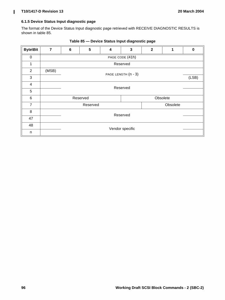
T10/1417-D Revision 13 20 March 2004
96 Working Draft SCSI Block Commands - 2 (SBC-2)
6.1.5 Device Status Input diagnostic page
The format of the Device Status Input diagnostic page retrieved with RECEIVE DIAGNOSTIC RESULTS is shown in table 85.
Table 85 — Device Status Input diagnostic page
Byte\Bit 7 6 5 4 3 2 1 0
0 PAGE CODE (41h)
1 Reserved
2 (MSB)PAGE LENGTH (n - 3)
3 (LSB)
4Reserved
5
6 Reserved Obsolete
7 Reserved Obsolete
8Reserved
47
48Vendor specific
n
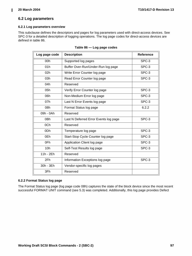
20 March 2004 T10/1417-D Revision 13
Working Draft SCSI Block Commands - 2 (SBC-2) 97
6.2 Log parameters
6.2.1 Log parameters overview
This subclause defines the descriptors and pages for log parameters used with direct-access devices. See SPC-3 for a detailed description of logging operations. The log page codes for direct-access devices are defined in table 86.
6.2.2 Format Status log page
The Format Status log page (log page code 08h) captures the state of the block device since the most recent successful FORMAT UNIT command (see 5.3) was completed. Additionally, this log page provides Defect
Table 86 — Log page codes
Log page code Description Reference
00h Supported log pages SPC-3
01h Buffer Over-Run/Under-Run log page SPC-3
02h Write Error Counter log page SPC-3
03h Read Error Counter log page SPC-3
04h Reserved
05h Verify Error Counter log page SPC-3
06h Non-Medium Error log page SPC-3
07h Last N Error Events log page SPC-3
08h Format Status log page 6.2.2
09h - 0Ah Reserved
0Bh Last N Deferred Error Events log page SPC-3
0Ch Reserved
0Dh Temperature log page SPC-3
0Eh Start-Stop Cycle Counter log page SPC-3
0Fh Application Client log page SPC-3
10h Self-Test Results log page SPC-3
11h - 2Eh Reserved
2Fh Information Exceptions log page SPC-3
30h - 3Eh Vendor-specific log pages
3Fh Reserved

T10/1417-D Revision 13 20 March 2004
98 Working Draft SCSI Block Commands - 2 (SBC-2)
Management information for the device server. Table 87 defines the parameter codes for the Format Status log page.
Event counts are returned as a result of the LOG SENSE command. LOG SELECT shall not pre-set (a value other than zero) for any of the event counts listed in table 87. Attempts to change these event counts by issuing a LOG SELECT with these fields set to non-zero values is not considered an error and shall have no effect on the saved values.
Editor’s Note 15: What does pre-set mean?
All of the log parameters described above shall be reported as the value - 1 (FFh in all bytes of the log parameter) if the most recent FORMAT UNIT command failed. Individual log parameters described above shall be reported as the value - 1 if no such information is available.
Editor’s Note 16: What does the above mean?
The FORMAT DATA OUT field contains the entire FORMAT UNIT parameter list (see 5.3.1) of the most recently successful FORMAT UNIT command completed. This includes:
a) the defect list header (4 bytes); b) the initialization pattern descriptor, if any (variable number of bytes); andc) the defect descriptor(s), if any (variable number of bytes).
The GROWN DEFECTS DURING CERTIFICATION field is a count of the number of defects detected as a result of performing certification during processing of a FORMAT UNIT command. This count reflects only those defects detected and replaced that were not already part of the PLIST or GLIST. If a certification pass was not performed the GROWN DEFECTS DURING CERTIFICATION field shall be set to zero.
The TOTAL BLOCKS REALLOCATED DURING FORMAT field is a count of the total number of blocks that have been reallocated since the completion of the last successful FORMAT UNIT command.
The POWER ON MINUTES SINCE FORMAT field represents the unsigned number of usage minutes (i.e., power applied regardless of power state) that have elapsed since the most recently successful FORMAT UNIT command.
Upon receiving the FORMAT UNIT command, the device server should set all fields within the Format Status log page to reflect no such information being available. Only upon successful completion of the FORMAT UNIT command should the device server update the affected fields.
The target save disable (TSD) bit shall always be set to zero to indicate that the device server provides an implicit saving frequency.
Table 87 — Format Status log page parameter codes
Parameter code Description
0000h Format DATA OUT
0001h Grown defects during certification
0002h Total blocks reallocated during format
0003h Total new blocks reallocated
0004h Power on minutes since format
0005h - 7FFFh Reserved
8000h - FFFFh Vendor-specific parameters

20 March 2004 T10/1417-D Revision 13
Working Draft SCSI Block Commands - 2 (SBC-2) 99
NOTE 22 - Removable media device servers may save log page information with the medium in a vendor-specific manner and location.
6.3 Mode parameters
6.3.1 Mode parameters overview
This subclause defines the descriptors and pages for mode parameters used with direct-access device types.
The mode parameter list, including the mode parameter header and mode block descriptor are described in SPC-3.
The MEDIUM TYPE field in the mode parameter header (see SPC-3) shall be set to 00h.
The DEVICE-SPECIFIC PARAMETER field (see table 88) is contained in the mode parameter header (see SPC-3).
When used with the MODE SELECT command the write protect (WP) bit is not defined.
When used with the MODE SENSE command a WP bit set to zero indicates that the medium is write enabled. A WP bit set to one indicates that the medium is write protected.
When used with the MODE SELECT command, the DPOFUA bit is reserved.
When used with the MODE SENSE command, a DPOFUA bit set to zero indicates that the device server does not support the DPO and FUA bits. When used with the MODE SENSE command, a DPOFUA bit set to one indicates that the device server supports the DPO and FUA bits (see 4.9).
The DENSITY CODE field is contained in the mode parameter block descriptor (see SPC-3). This field is reserved for direct-access devices.
Table 88 — DEVICE-SPECIFIC PARAMETER field
Bit 7 6 5 4 3 2 1 0
WP Reserved DPOFUA Reserved

T10/1417-D Revision 13 20 March 2004
100 Working Draft SCSI Block Commands - 2 (SBC-2)
The mode page codes for direct-access devices are shown in table 89.
In some cases the mode pages do not apply to the entire logical unit. This is controlled by the Notch And Partition mode mode (see 6.3.3).
Editor’s Note 17: the Notch and Partition mode page might be made obsolete by 04-082
Table 89 — Mode page codes for direct-access devices
Mode page code Description Reference
00h Vendor-specific (does not require page format)
01h Read-Write Error Recovery mode page 6.3.4
02h Disconnect-Reconnect mode page SPC-3
03h Obsolete (Format Device mode page)
04h Obsolete (Rigid Disk Geometry mode page)
05h Obsolete (Flexible Disk mode page)
06h Reserved
07h Verify Error Recovery mode page 6.3.5
08h Caching mode page 6.3.2
09h Obsolete
0Ah Control mode page SPC-3
0Bh Obsolete (Medium Types Supported mode page)
0Ch Notch And Partition mode page 6.3.3
0Dh Obsolete
0Eh - 0Fh Reserved
10h XOR Control mode page 6.3.6
11h - 17h Reserved
18h Protocol-Specific LUN mode page SPC-3
19h Protocol-Specific Port mode page SPC-3
1Ah Power Condition mode page SPC-3
1Bh Reserved
1Ch Informational Exceptions Control mode page SPC-3
1Dh - 1Fh Reserved
20h - 3Eh Vendor-specific (does not require page format)
3Fh Return all mode pages (valid only for the MODE SENSE command) SPC-3

20 March 2004 T10/1417-D Revision 13
Working Draft SCSI Block Commands - 2 (SBC-2) 101
6.3.2 Caching mode page
The Caching mode page (see table 90) defines the parameters that affect the use of the cache.
The parameters savable (PS) bit is only used with the MODE SENSE command. This bit is reserved with the MODE SELECT command. A PS bit set to one indicates that the device server is capable of saving the mode page in a non-volatile vendor-specific location. If the PS is set to one in MODE SENSE data then the mode page shall be savable by issuing a MODE SELECT command with the SP bit set to one.
An initiator control (IC) enable bit set to one specifies that the device server use the NUMBER OF CACHE SEGMENTS field or the CACHE SEGMENT SIZE field, dependent upon the SIZE bit, to control the caching algorithm rather than the device server’s own adaptive algorithm.
An abort pre-fetch (ABPF) bit set to one, with the DRA bit set to zero, specifies that the device server abort a pre-fetch upon receipt of a new command. An ABPF bit set to one takes precedence over the value specified in the MINIMUM PRE-FETCH field. An ABPF bit set to zero, with the DRA bit set to zero, specifies that the termination of any active pre-fetch is dependent upon Caching mode page bytes 4 through 11 and is operation and/or vendor-specific.
A caching analysis permitted (CAP) bit set to one specifies that the device server perform caching analysis during subsequent operations. A CAP bit set to zero specifies that caching analysis be disabled to reduce overhead time or to prevent nonpertinent operations from impacting tuning values.
A discontinuity (DISC) bit set to one specifies that the device server continue the pre-fetch across time discontinuities (e.g., across cylinders) up to the limits of the buffer, or segment, space available for the pre-fetch. A DISC bit set to zero specifies that pre-fetches be truncated or wrapped at time discontinuities.
Table 90 — Caching mode page
Byte\Bit 7 6 5 4 3 2 1 0
0 PS Reserved PAGE CODE (08h)
1 PAGE LENGTH (12h)
2 IC ABPF CAP DISC SIZE WCE MF RCD
3 DEMAND READ RETENTION PRIORITY WRITE RETENTION PRIORITY
4 (MSB)DISABLE PRE-FETCH TRANSFER LENGTH
5 (LSB)
6 (MSB)MINIMUM PRE-FETCH
7 (LSB)
8 (MSB)MAXIMUM PRE-FETCH
9 (LSB)
10 (MSB)MAXIMUM PRE-FETCH CEILING
11 (LSB)
12 FSW LBCSS DRA Vendor specific Reserved
13 NUMBER OF CACHE SEGMENTS
14 (MSB)CACHE SEGMENT SIZE
15 (LSB)
16 Reserved
17 (MSB)NON CACHE SEGMENT SIZE
19 (LSB)

T10/1417-D Revision 13 20 March 2004
102 Working Draft SCSI Block Commands - 2 (SBC-2)
A size enable (SIZE) bit set to one specifies that the CACHE SEGMENT SIZE field be used to control caching segmentation. A SIZE bit set to zero specifies that the NUMBER OF CACHE SEGMENTS field be used to control caching segmentation. Simultaneous use of both the number of segments and the segment size is vendor-specific.
A write cache enable (WCE) bit set to zero specifies that the device server shall return GOOD status for a WRITE command after successfully writing all of the data to the medium. A WCE bit set to one specifies that the device server may return GOOD status for a WRITE command after successfully receiving the data and prior to having successfully written it to the medium.
A multiplication factor (MF) bit set to zero specifies that the device server shall interpret the MINIMUM and MAXIMUM PRE-FETCH fields in terms of the number of logical blocks for each of the respective types of pre-fetch. An MF bit set to one specifies that the device server shall interpret the MINIMUM and MAXIMUM PRE-FETCH fields to be specified in terms of a scalar number that, when multiplied by the number of logical blocks to be transferred for the current command, yields the number of logical blocks for each of the respective types of pre-fetch.
A read cache disable (RCD) bit set to zero specifies that the device server may return data requested by a READ command by accessing either the cache or medium. A RCD bit set to one specifies that the device server shall transfer all of the data requested by a READ command from the medium (i.e., data shall not be transferred from the cache).
The DEMAND READ RETENTION PRIORITY field (see table 91) advises the device server the retention priority to assign for data read into the cache that has also been transferred from the logical unit to the application client.
The WRITE RETENTION PRIORITY field advises the device server the retention priority to assign for data written into the cache that has also been transferred from the cache memory to the medium.
An anticipatory pre-fetch occurs when data is placed in the cache that has not been requested. This may happen in conjunction with the reading of data that has been requested. All the following parameters give an indication to the device server how it should manage the cache based on the last READ command. An anticipatory pre-fetch may occur based on other information. All the remaining caching parameters are only recommendations to the device server and should not cause a CHECK CONDITION to occur if the device server is not able to satisfy the request.
The DISABLE PRE-FETCH TRANSFER LENGTH field specifies the selective disabling of anticipatory pre-fetch on long transfer lengths. The value in this field is compared to the number of blocks requested by the current
Table 91 — Demand read retention priority and write retention priority
Value Description
0h The device server should not distinguish between retaining the indicated data and data placed into the cache memory by other means (e.g., pre-fetch).
1h
Demand read retention priority: Data put into the cache via a READ command should be replaced sooner (i.e., has lower priority) than data placed into the cache by other means (e.g., pre-fetch).
Write retention priority: Data put into the cache during a WRITE or WRITE AND VERIFY command should be replaced sooner (i.e., has lower priority) than data placed into the cache by other means (e.g., pre-fetch).
2h - Eh Reserved
Fh
Demand read retention priority: Data put into the cache via a READ command should not be replaced if there is other data in the cache that was placed into the cache by other means (e.g., pre-fetch) and it may be replaced (i.e., it is not locked).
Write retention priority: Data put into the cache during a WRITE or WRITE AND VERIFY command should not be replaced if there is other data in the cache that was placed into the cache by other means (e.g., pre-fetch) and it may be replaced (i.e., it is not locked).

20 March 2004 T10/1417-D Revision 13
Working Draft SCSI Block Commands - 2 (SBC-2) 103
READ command. If the number of blocks is greater than the disable pre-fetch transfer length, then an anticipatory pre-fetch is not done for the command. Otherwise the device server should attempt an anticipatory pre-fetch. If the pre-fetch disable transfer length is zero, then all anticipatory pre-fetching is disabled for any request for data, including those for zero logical blocks.
The MINIMUM PRE-FETCH field specifies either a number of blocks or a scalar multiplier of the TRANSFER LENGTH, depending upon the setting of the MF bit. In either case, the resulting number of blocks is the number to pre-fetch regardless of the delays it might cause in processing subsequent commands.
The pre-fetching operation begins at the logical block after the last logical block of the previous READ command. Pre-fetching shall always halt before exceeding the end of the medium. Errors that occur during the pre-fetching operation shall not be reported to the application client unless the device server is unable to, as a result of the error, process subsequent commands correctly. In this case the error may be reported either as an error for the current READ command, or as a deferred error, at the discretion of the device server and according to the rules for reporting deferred errors.
If the pre-fetch has read more than the amount of data specified by the MINIMUM PRE-FETCH field, then pre-fetching should be terminated whenever another command is ready to be processed. This consideration is ignored when the MINIMUM PRE-FETCH field value is equal to the MAXIMUM PRE-FETCH field value.
The MAXIMUM PRE-FETCH field specifies either a number of blocks or a scalar multiplier of the TRANSFER LENGTH, depending upon the setting of the MF bit. In either case, the resulting number of blocks is the number to pre-fetch if the pre-fetch does not delay processing of subsequent commands.
The MAXIMUM PRE-FETCH field contains the maximum amount of data to pre-fetch into the cache as a result of one READ command. It is used in conjunction with the DISABLE PRE-FETCH TRANSFER LENGTH and MAXIMUM PRE- FETCH CEILING parameters to trade off pre-fetching new data with displacing old data already stored in the cache.
The MAXIMUM PRE-FETCH CEILING field specifies an upper limit on the number of logical blocks computed as the maximum pre-fetch. If this number of blocks is greater than the MAXIMUM PRE-FETCH, then the number of logical blocks to pre-fetch shall be truncated to the value stored in the MAXIMUM PRE-FETCH CEILING field.
NOTE 23 - If the MF bit is set to one the MAXIMUM PRE-FETCH CEILING field is useful in limiting the amount of data to be pre-fetched.
A force sequential write (FSW) bit set to one specifies that multiple block writes are to be transferred from the application client data-out buffer and written to the medium in an ascending, sequential, logical block order. An FSW bit set to zero specifies that the device server is allowed to reorder the sequence of writing addressed logical blocks in order to achieve a faster command completion.
A logical block cache segment size (LBCSS) bit set to one specifies that the CACHE SEGMENT SIZE field units shall be interpreted as logical blocks. An LBCSS bit set to zero specifies that the CACHE SEGMENT SIZE field units shall be interpreted as bytes. The LBCSS shall not impact the units of other fields.
A disable read-ahead (DRA) bit set to one specifies that the device server not read into the buffer any logical blocks beyond the addressed logical block(s). A DRA bit set to zero specifies that the device server may continue to read logical blocks into the buffer beyond the addressed logical block(s).
The NUMBER OF CACHE SEGMENTS field specifies the number of segments into which the device server shall divide the cache.
The CACHE SEGMENT SIZE field specifies the segment size in bytes. The CACHE SEGMENT SIZE field is valid only when the SIZE bit is set to one.
A NON CACHE SEGMENT SIZE field that is greater than zero specifies that the device server allocate for a buffer function when all other cache segments are occupied by data to be retained. If the number is at least one, caching functions in the other segments need not be impacted by cache misses to perform the SCSI buffer function. A NON CACHE SEGMENT SIZE field set to zero is vendor-specific. If the sum of the NON CACHE SEGMENT SIZE field value plus the CACHE SEGMENT SIZE field value is greater than the buffer size, the result is vendor-specific.

T10/1417-D Revision 13 20 March 2004
104 Working Draft SCSI Block Commands - 2 (SBC-2)
6.3.3 Notch And Partition mode page
Editor’s Note 18: The Notch and Partition mode page might be made obsolete by 04-082
The Notch And Partition mode page (see table 92) contains parameters for direct-access devices that implement a variable number of blocks per cylinder and support this mode page. Each section of the block device with a different number of blocks per cylinder, than other sections, is referred to as a notch.
The parameters savable (PS) bit is only used with the MODE SENSE command. This bit is reserved with the MODE SELECT command. A PS bit set to one indicates that the device server is capable of saving the mode page in a non-volatile vendor-specific location.
A notched device (ND) bit set to zero indicates that the block device is not notched and that all other parameters in this mode page shall be returned as zero by the device server. A ND bit set to one indicates that the block device is notched. For each supported active notch value this mode page defines the starting and ending boundaries of the notch.
A logical or physical notch (LPN) bit set to zero specifies that the boundaries are based on the physical parameters of the block device. The cylinder is considered most significant, the head least significant. A LPN bit set to one specifies that the notch boundaries are based on logical blocks of the block device.
The MAXIMUM NUMBER OF NOTCHES field indicates the maximum number of notches supported by the logical unit. This field shall be reported as unchangeable.
The ACTIVE NOTCH field indicates the notch to which this and subsequent MODE SELECT and MODE SENSE commands shall refer, until the active notch is changed by a subsequent MODE SELECT command. The value of the active notch shall be greater than or equal to 0000h and less than or equal to the maximum number of notches. An ACTIVE NOTCH field set to zero indicates that this and subsequent MODE SELECT and MODE SENSE commands refer to the parameters that apply across all notches.
The STARTING BOUNDARY field indicates the beginning of the active notch or, if the active notch is zero, the beginning boundary of the logical unit. If the LPN bit is set to one, then the four bytes represent an LBA. If the
Table 92 — Notch And Partition mode page
Byte\Bit 7 6 5 4 3 2 1 0
0 PS Reserved PAGE CODE (0Ch)
1 PAGE LENGTH (16h)
2 ND LPN Reserved
3 Reserved
4 (MSB)MAXIMUM NUMBER OF NOTCHES
5 (LSB)
6 (MSB)ACTIVE NOTCH
7 (LSB)
8 (MSB)STARTING BOUNDARY
11 (LSB)
12 (MSB)ENDING BOUNDARY
15 (LSB)
16 (MSB)PAGES NOTCHED
23 (LSB)

20 March 2004 T10/1417-D Revision 13
Working Draft SCSI Block Commands - 2 (SBC-2) 105
LPN bit is set to zero, then the three most significant bytes shall represent the cylinder number and the least significant byte shall represent the head number. This field shall be reported as unchangeable. When used with the MODE SELECT command this field is ignored.
The ENDING BOUNDARY field indicates the ending of the active notch or, if the active notch is zero, the ending of the logical unit. If the LPN bit is set to one, then the four bytes represent an LBA. If the LPN bit is set to zero, then the three most significant bytes shall represent the cylinder number and the least significant byte shall represent the head number. This field shall be reported as unchangeable. When used with the MODE SELECT command this field is ignored.
Each notch shall span a set of consecutive logical blocks on the block device, the notches shall not overlap, and no logical block shall be excluded from a notch.
The PAGES NOTCHED field is a bit map of the mode page codes that indicates mode pages that contain parameters that may be different for different notches. The most significant bit of this field corresponds to PAGE CODE 3Fh and the least significant bit corresponds to PAGE CODE 00h. If a bit is set to one, then the corresponding mode page contains parameters that may be different for different notches. If a bit is set to zero, then the corresponding mode page contains parameters that are constant for all notches. This field shall be reported as unchangeable.
6.3.4 Read-Write Error Recovery mode page
The Read-Write Error Recovery mode page (see table 93) specifies the error recovery parameters the device server shall use during any command that performs a read or write operation to the medium (e.g., READ, WRITE, WRITE AND VERIFY, etc.).
The parameters savable (PS) bit is only used with the MODE SENSE command. This bit is reserved with the MODE SELECT command. A PS bit set to one indicates that the device server is capable of saving the mode page in a non-volatile vendor-specific location.
An automatic write reallocation enabled (AWRE) bit set to zero specifies that the device server shall not perform automatic reallocation of defective logical blocks during write operations.
An AWRE bit set to one specifies that the device server shall enable automatic reallocation to be performed during write operations. The automatic reallocation shall be performed only if the device server has the valid data (e.g., original data in the buffer or recovered from the medium). The valid data shall be placed in the reallocated block. Error reporting as required by the error recovery bits (EER, PER, DTE, and DCR) shall be
Table 93 — Read-Write Error Recovery mode page
Byte\Bit 7 6 5 4 3 2 1 0
0 PS Reserved PAGE CODE (01h)
1 PAGE LENGTH (0Ah)
2 AWRE ARRE TB RC EER PER DTE DCR
3 READ RETRY COUNT
4 Obsolete
5 Obsolete
6 Obsolete
7 Reserved Restricted for MMC-4
8 WRITE RETRY COUNT
9 Reserved
10 (MSB)RECOVERY TIME LIMIT
11 (LSB)

T10/1417-D Revision 13 20 March 2004
106 Working Draft SCSI Block Commands - 2 (SBC-2)
performed only after completion of the reallocation. The reallocation operation shall report any failures that occur. See the REASSIGN BLOCKS command (see 5.18) for error procedures.
An automatic read reallocation enabled (ARRE) bit set to zero specifies that the device server shall not perform automatic reallocation of defective logical blocks during read operations.
An ARRE bit set to one specifies that the device server shall enable automatic reallocation of defective logical blocks during read operations. All error recovery actions required by the error recovery bits (TB, EER, PER, DTE, and DCR) shall be processed. The automatic reallocation shall then be performed only if the device server successfully recovers the data. The recovered data shall be placed in the reallocated block. Error reporting as required by the error recovery bits shall be performed only after completion of the reallocation. The reallocation process shall present any failures that occur. See the REASSIGN BLOCKS command (see 5.18) for error procedures.
A transfer block (TB) bit set to zero specifies that a logical block that is not recovered within the recovery limits specified shall not be transferred to the application client. A TB bit set to one specifies that a logical block that is not recovered within the recovery limits specified shall be transferred to the application client before CHECK CONDITION status is returned. The TB bit does not affect the action taken for recovered data.
NOTE 24 - Fabricated data may be data already in the buffer or any other vendor-specific data. This bit may be used in image processing, audio, or video applications.
A read continuous (RC) bit set to zero specifies that error recovery operations that cause delays are acceptable during the data transfer. Data shall not be fabricated.
An RC bit set to one specifies the device server shall transfer the entire requested length of data without adding delays to perform error recovery procedures. This implies that the device server may send data that is erroneous or fabricated in order to maintain a continuous flow of data. The device server shall assign priority to this bit over conflicting error control bits (EER, DCR, DTE, and PER) within this byte.

20 March 2004 T10/1417-D Revision 13
Working Draft SCSI Block Commands - 2 (SBC-2) 107
The individual bit definitions for EER, PER, DTE and DCR are contained in table 94.
NOTE 25 - An EER bit set to one may imply an increase in the probability of mis-detection or mis-correction. An EER bit set to zero allows the specified retry limit to be exhausted prior to using error correction codes.
Table 94 — Error recovery bit definitions
EER PER DTE DCR Description
1 - - -
An enable early recovery (EER) bit set to one specifies that the device server shall use the most expedient form of error recovery first. This bit only applies to data error recovery and it does not affect positioning retries and the message system error recovery procedures.
0 - - -An EER bit set to zero specifies that the device server shall use as error recovery procedure that minimizes the risk of mis-detection or mis-correction.
- 1 - - A post error (PER) bit set to one specifies that the device server shall report recovered errors.
- 0 - -A PER bit set to zero specifies that the device server shall not report recovered errors. Error recovery procedures shall be performed within the limits established by the error recovery parameters.
- - 1 - A DTE bit set to one specifies that the device server shall terminate the data-in or data-out buffer transfer upon detection of a recovered error.
- - 0 -A DTE bit set to zero specifies that the device server shall not terminate the data-in or data-out buffer transfer upon detection of a recovered error.
- - - 1 A disable correction (DCR) bit set to one specifies that error condition codes shall not be used for data error recovery.
- - - 0 A DCR bit set to zero allows the use of error condition codes for data error recovery.

T10/1417-D Revision 13 20 March 2004
108 Working Draft SCSI Block Commands - 2 (SBC-2)
The combinations of these bits are explained in table 95.
Table 95 — Combined error recovery parameter descriptions (part 1 of 2)
EER PER DTE DCR Description
0 0 0 0
The full number of retries (specified in the READ, WRITE or VERIFY RETRY COUNT field) and error correction are attempted to recover the data (EER and DCR bits set to zero). A CHECK CONDITION is not reported at the completion of the command for recovered errors (PER bit set to zero). The command terminates with CHECK CONDITION status before the transfer count is exhausted only if an unrecoverable error is detected. If an unrecoverable data error occurred, the data in the block with the unrecoverable error may or may not be transferred to the application client depending on the setting of the transfer block (TB) bit (read operation only).
0 0 0 1
Error correction is disabled (DCR bit set to one) so only the full number of retries (specified in the READ, WRITE or VERIFY RETRY COUNT field) are attempted to recover the data (EER bit set to zero). A CHECK CONDITION is not reported at the completion of the command for recoverable errors (PER bit set to zero). The command terminates with CHECK CONDITION status before the transfer count is exhausted only if an unrecoverable error is detected. If an unrecoverable data error occurred, the data in the block with the unrecoverable error may or may not be transferred to the application client depending on the setting of the transfer block (TB) bit (read operation only).
0 0 1 0 Invalid mode (the PER bit shall be set to one if DTE is set to one).a
0 0 1 1 Invalid mode (the PER bit shall be set to one if DTE is set to one).a
0 1 0 0
The full number of retries (specified in the READ, WRITE or VERIFY RETRY COUNT field) and error correction are attempted to recover the data (EER and DCR bits set to zero). The command terminates with CHECK CONDITION status before the transfer count is exhausted only if an unrecoverable error is detected. If an unrecoverable data error occurred, the data in the block with the unrecoverable error may or may not be transferred to the application client depending on the setting of the transfer block (TB) bit (read operation only). A CHECK CONDITION with a sense key of RECOVERED ERROR is reported at the completion of the command for any recoverable error that occurs (PER bit set to one). The INFORMATION field in the sense data shall contain the LBA of the last recovered error that occurred during the transfer.
0 1 0 1
Error correction is disabled (DCR bit set to one) so only the full number of retries (specified in the READ, WRITE or VERIFY RETRY COUNT field) are attempted to recover the data (EER bit set to zero). The command terminates with CHECK CONDITION status before the transfer count is exhausted only if an unrecoverable error is detected. If an unrecoverable data error occurred, the data in the block with the unrecoverable error may or may not be transferred to the application client depending on the setting of the transfer block (TB) bit (read operation only). A CHECK CONDITION with a sense key of RECOVERED ERROR is reported at the completion of the command for any recoverable error that occurs (PER bit set to one). The INFORMATION field in the sense data shall contain the LBA of the last recovered error that occurred during the transfer.
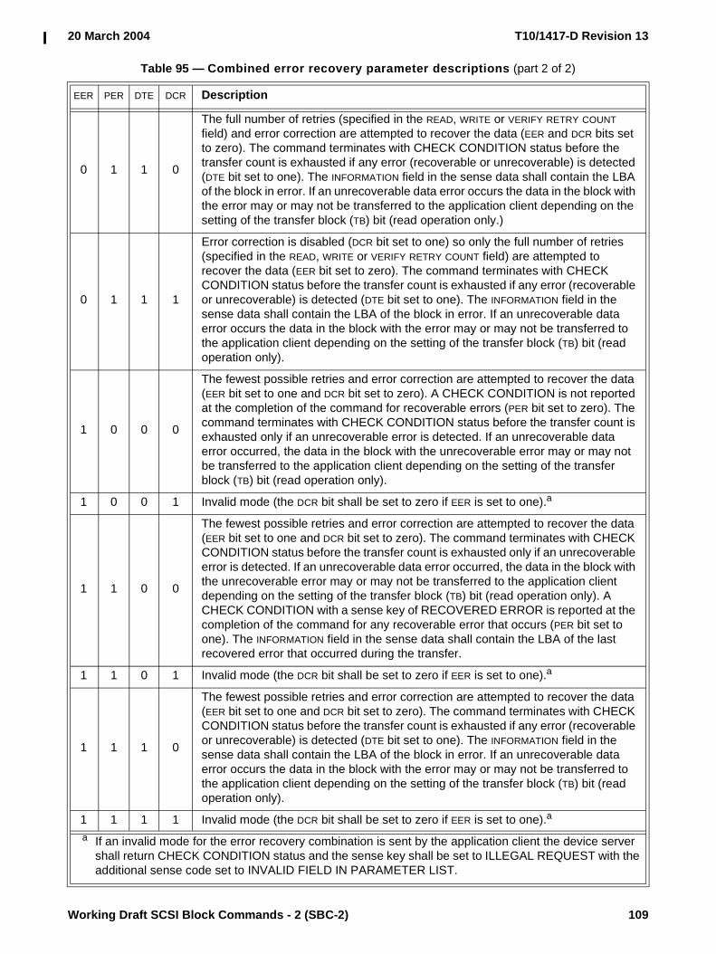
20 March 2004 T10/1417-D Revision 13
Working Draft SCSI Block Commands - 2 (SBC-2) 109
0 1 1 0
The full number of retries (specified in the READ, WRITE or VERIFY RETRY COUNT field) and error correction are attempted to recover the data (EER and DCR bits set to zero). The command terminates with CHECK CONDITION status before the transfer count is exhausted if any error (recoverable or unrecoverable) is detected (DTE bit set to one). The INFORMATION field in the sense data shall contain the LBA of the block in error. If an unrecoverable data error occurs the data in the block with the error may or may not be transferred to the application client depending on the setting of the transfer block (TB) bit (read operation only.)
0 1 1 1
Error correction is disabled (DCR bit set to one) so only the full number of retries (specified in the READ, WRITE or VERIFY RETRY COUNT field) are attempted to recover the data (EER bit set to zero). The command terminates with CHECK CONDITION status before the transfer count is exhausted if any error (recoverable or unrecoverable) is detected (DTE bit set to one). The INFORMATION field in the sense data shall contain the LBA of the block in error. If an unrecoverable data error occurs the data in the block with the error may or may not be transferred to the application client depending on the setting of the transfer block (TB) bit (read operation only).
1 0 0 0
The fewest possible retries and error correction are attempted to recover the data (EER bit set to one and DCR bit set to zero). A CHECK CONDITION is not reported at the completion of the command for recoverable errors (PER bit set to zero). The command terminates with CHECK CONDITION status before the transfer count is exhausted only if an unrecoverable error is detected. If an unrecoverable data error occurred, the data in the block with the unrecoverable error may or may not be transferred to the application client depending on the setting of the transfer block (TB) bit (read operation only).
1 0 0 1 Invalid mode (the DCR bit shall be set to zero if EER is set to one).a
1 1 0 0
The fewest possible retries and error correction are attempted to recover the data (EER bit set to one and DCR bit set to zero). The command terminates with CHECK CONDITION status before the transfer count is exhausted only if an unrecoverable error is detected. If an unrecoverable data error occurred, the data in the block with the unrecoverable error may or may not be transferred to the application client depending on the setting of the transfer block (TB) bit (read operation only). A CHECK CONDITION with a sense key of RECOVERED ERROR is reported at the completion of the command for any recoverable error that occurs (PER bit set to one). The INFORMATION field in the sense data shall contain the LBA of the last recovered error that occurred during the transfer.
1 1 0 1 Invalid mode (the DCR bit shall be set to zero if EER is set to one).a
1 1 1 0
The fewest possible retries and error correction are attempted to recover the data (EER bit set to one and DCR bit set to zero). The command terminates with CHECK CONDITION status before the transfer count is exhausted if any error (recoverable or unrecoverable) is detected (DTE bit set to one). The INFORMATION field in the sense data shall contain the LBA of the block in error. If an unrecoverable data error occurs the data in the block with the error may or may not be transferred to the application client depending on the setting of the transfer block (TB) bit (read operation only).
1 1 1 1 Invalid mode (the DCR bit shall be set to zero if EER is set to one).a
a If an invalid mode for the error recovery combination is sent by the application client the device server shall return CHECK CONDITION status and the sense key shall be set to ILLEGAL REQUEST with the additional sense code set to INVALID FIELD IN PARAMETER LIST.
Table 95 — Combined error recovery parameter descriptions (part 2 of 2)
EER PER DTE DCR Description

T10/1417-D Revision 13 20 March 2004
110 Working Draft SCSI Block Commands - 2 (SBC-2)
The READ and WRITE RETRY COUNT fields specify the number of times that the device server shall attempt its recovery algorithm during read and write operations, respectively. If the RETRY COUNT field and the RECOVERY TIME LIMIT field are both specified in a MODE SELECT command, the field that requires the least time for data error recovery actions shall have priority.
The RECOVERY TIME LIMIT field specifies in milliseconds the maximum time duration that the device server shall use for data error recovery procedures. The device server may round this value as described in SPC-3. The limit in this field specifies the maximum error recovery time allowed for any individual logical block. A RECOVERY TIME LIMIT field set to zero specifies that the device server shall use its default value.
If both RETRY COUNT and RECOVERY TIME LIMIT are specified, the field that specifies the recovery action of least duration shall have priority.
6.3.5 Verify Error Recovery mode page
The Verify Error Recovery mode page (see table 96) specifies the error recovery parameters the device server shall use during the VERIFY command and the verify operation of the WRITE AND VERIFY command.
The parameters savable (PS) bit is only used with the MODE SENSE command. This bit is reserved with the MODE SELECT command. A PS bit set to one indicates that the device server is capable of saving the mode page in a non-volatile vendor-specific location.
The AWRE bit as defined in the Read-Write Error Recovery mode page (see 6.3.4) applies to the WRITE AND VERIFY command. The VERIFY command shall not perform automatic reallocation.
The EER, PER, DTE, and DCR bits are defined in 6.3.4. The combinations of these bits are defined in table 95.
The VERIFY RETRY COUNT field specifies the number of times that the device server shall attempt its recovery algorithm during a verify operation. If the verify retry count and the VERIFY RECOVERY TIME LIMIT are both specified, the one that requires the least time for data error recovery actions shall have priority.
The VERIFY RECOVERY TIME LIMIT field specifies in milliseconds the maximum time duration that the device server shall use error recovery procedures to recover data for an individual logical block. The device server may round this value as described in SPC-3. If the VERIFY RETRY COUNT and the VERIFY RECOVERY TIME LIMIT are both specified, the one that requires the least time for data error recovery actions shall have priority.
NOTE 26 - To disable all types of correction and retries the application client should set the EER bit to zero, the PER, DTE, and DCR bits to one and the number of retries and recovery time limit to zero.
Table 96 — Verify Error Recovery mode page
Byte\Bit 7 6 5 4 3 2 1 0
0 PS Reserved PAGE CODE (07h)
1 PAGE LENGTH (0Ah)
2 Reserved EER PER DTE DCR
3 VERIFY RETRY COUNT
4 Obsolete
5Reserved
9
10 (MSB)VERIFY RECOVERY TIME LIMIT
11 (LSB)

20 March 2004 T10/1417-D Revision 13
Working Draft SCSI Block Commands - 2 (SBC-2) 111
6.3.6 XOR Control mode page
The XOR Control mode page (see table 97) provides the initiator with the means to obtain or modify certain XOR operating parameters of the target.
The parameters savable (PS) bit is only used with the MODE SENSE command. This bit is reserved with the MODE SELECT command. A PS bit set to one indicates that the device server is capable of saving the mode page in a non-volatile vendor-specific location.
An XOR disable (XORDIS) bit set to zero enables the XOR operations within a device. An XORDIS bit set to one shall disable the XOR operations within a device. If the XORDIS bit is set to one and an XOR command is sent to the logical unit, the device server shall terminate the command with CHECK CONDITION status with the sense key set to ILLEGAL REQUEST with the additional sense code set to INVALID COMMAND OPERATION CODE.
The MAXIMUM XOR WRITE SIZE field specifies the maximum transfer length in blocks that the target accepts for a single XDWRITE or XPWRITE command.
6.4 Vital product data (VPD) parameters
6.4.1 VPD parameters overview
This subclause defines the VPD pages used with direct-access block type devices. See SPC-3 for VPD pages used with all device types.
The VPD page codes specific to direct-access devices are defined in table 98.
Table 97 — XOR Control mode page
Byte\Bit 7 6 5 4 3 2 1 0
0 PS Reserved PAGE CODE (10h)
1 PAGE LENGTH (16h)
2 Reserved XORDIS Reserved
3 Reserved
4 (MSB)MAXIMUM XOR WRITE SIZE
7 (LSB)
8Reserved
11
12Obsolete
19
20Reserved
21
22Obsolete
23
Table 98 — Direct-access device VPD page codes
VPD page code VPD page name Reference Support requirements
B0h Block Limits VPD page 6.4.2 Optional
B1h - BFh Reserved for this device type

T10/1417-D Revision 13 20 March 2004
112 Working Draft SCSI Block Commands - 2 (SBC-2)
6.4.2 Block Limits VPD page
The Block Limits VPD page (see table 99) provides the application client with the means to obtain certain operating parameters of the logical unit.
The PERIPHERAL QUALIFIER field and the PERIPHERAL DEVICE TYPE field are defined in SPC-3.
The PAGE CODE field shall be set to B0h.
The PAGE LENGTH field is defined in SPC-3.
The OPTIMAL TRANSFER LENGTH GRANULARITY field indicates the optimal transfer length granularity in blocks for a single PRE-FETCH, READ, VERIFY, WRITE, WRITE AND VERIFY, XDREAD, XDWRITE, XDWRITEREAD, or XPWRITE command. Transfers with transfer lengths not equal to a multiple of this value may incur significant delays in processing.
The MAXIMUM TRANSFER LENGTH field indicates the maximum transfer length in blocks that the target accepts for a single PRE-FETCH, READ, VERIFY, WRITE, WRITE AND VERIFY, XDREAD, XDWRITE, XDWRITEREAD, or XPWRITE command. Requests for transfer lengths exceeding this limit result in CHECK CONDITION status with a sense key of ILLEGAL REQUEST and an additional sense code of INVALID FIELD IN CDB. A MAXIMUM TRANSFER LENGTH field set to zero indicates that there is no reported limit on the transfer length.
The OPTIMAL TRANSFER LENGTH field indicates the optimal transfer length in blocks for a single PRE-FETCH, READ, VERIFY, WRITE, WRITE AND VERIFY, XDREAD, XDWRITE, XDWRITEREAD, or XPWRITE command. Transfers with transfer lengths exceeding this value may incur significant delays in processing.
Table 99 — Block Limits VPD page
Byte\Bit 7 6 5 4 3 2 1 0
0 PERIPHERAL QUALIFIER PERIPHERAL DEVICE TYPE
1 PAGE CODE (B0h)
2 Reserved
3 PAGE LENGTH (0Ch)
4Reserved
5
6 (MSB)OPTIMAL TRANSFER LENGTH GRANULARITY
7 (LSB)
8 (MSB)MAXIMUM TRANSFER LENGTH
11 (LSB)
12 (MSB)OPTIMAL TRANSFER LENGTH
15 (LSB)

20 March 2004 T10/1417-D Revision 13
Working Draft SCSI Block Commands - 2 (SBC-2) 113
Annex A(informative)
XOR command examples
A.1 XOR command examples overviewThis annex provides XOR command examples in storage array controller supervised configurations.
A.2 Update write operationFigure A.1 illustrates a read-modify-write operation supervised by a storage array controller. The example uses a supervising storage array controller, a data disk device (holding protected user data), and a parity disk device (holding check data). In this example, the data and parity devices are on separate SCSI physical interconnects, and thus are not capable of peer-to-peer interaction. Three SCSI commands are used: XDWRITE, XDREAD, and XPWRITE. XDWRITEREAD may be used in place of any sequence of XDWRITE followed by XDREAD.
The supervising storage array controller begins by sending user data to the data disk device using an XDWRITE command. It also initiates an XPWRITE command to the parity disk device (the supervising storage array controller does not yet have the intermediate XOR data for this command; the purpose of issuing the XPWRITE command at this time is to cause the parity disk device to begin reading XOR data from its medium to its buffer memory).
The data disk device reads old user data from its medium, performs an XOR operation using the old user data and the user data from the supervising storage array controller, stores the resulting intermediate XOR data in its buffer memory, and writes the user data from the supervising storage array controller to its medium. The supervising storage array controller reads the resulting intermediate XOR data from the buffer memory by sending the data disk device an XDREAD command.
The supervising storage array controller makes the resulting intermediate XOR data (read with the XDREAD command) available to the parity disk device for the already issued XPWRITE command. The parity disk

T10/1417-D Revision 13 20 March 2004
114 Working Draft SCSI Block Commands - 2 (SBC-2)
device performs an XOR operation using the intermediate XOR data and the XOR data in its buffer memory. The resulting new XOR data is written to the medium.
Figure A.1 — Update write operation (storage array controller supervised)
A.3 Regenerate operationFigure A.2 illustrates a regenerate operation supervised by a storage array controller. The example uses a supervising storage array controller and three disk devices. In this example, all three disk devices are on separate SCSI physical interconnects, and thus are not capable of peer-to-peer interaction. Three SCSI commands are used: READ, XDWRITE, and XDREAD. XDWRITEREAD may be used in place of any sequence of XDWRITE followed by XDREAD.
The supervising storage array controller begins by issuing a READ command to disk device 1. The data received from this command is sent by the supervising storage array controller to disk device 2 using an XDWRITE command with a DISABLE WRITE bit set to one. Disk device 2 reads data from its medium, performs an XOR operation using that data and the data received from the supervising storage array controller, and stores the resulting intermediate XOR data in its buffer memory. The supervising storage array controller retrieves the intermediate XOR data from the buffer memory by issuing an XDREAD command to disk device 2. The supervising storage array controller issues XDWRITE and XDREAD commands in the same manner to disk device 3.
IntermediateXOR data buffer
Diskmedia
XOR 1.1 Olduser data
1.2. New user data
1. XDWRITEData-out contains
new user data
2. XDREADData-in contains
intermediate XOR data
User data
IntermediateXOR data
Supervising arraycontroller
Por
t 1Po
rt 2
Disk drive
Diskmedia
XOR 3.1. Olduser data
3.2. New user data
Disk drive
3. XPWRITEData-out contains
intermediate XOR data

20 March 2004 T10/1417-D Revision 13
Working Draft SCSI Block Commands - 2 (SBC-2) 115
The resulting data from disk device 3 is the regenerated user data.
Figure A.2 — Regenerate operation (storage array controller supervised)
A.4 Rebuild operationFigure A.3 illustrates a rebuild operation supervised by a storage array controller. The example uses a supervising storage array controller, two disk devices as the source devices, and one disk device as the rebuild device. In this example, all three disk devices are on separate SCSI physical interconnects, and thus are not capable of peer-to-peer interaction. Four SCSI commands are used: READ, XDWRITE, XDREAD, and WRITE. XDWRITEREAD may be used in place of any sequence of XDWRITE followed by XDREAD.
The supervising storage array controller begins by issuing a READ command to disk device 1. The data received from the READ command is sent by the supervising storage array controller to disk device 2 using an XDWRITE command with a DISABLE WRITE bit set to one. Disk device 2 reads data from its medium, performs an XOR operation using that data and the data received from the supervising storage array controller, and
IntermediateXOR data buffer
Diskmedia
XOR 2.1 data
2. XDWRITE orXDWRITEREADData-out contains
data
3. XDREAD orXDWRITEREAD part 2
Data-in containsintermediate XOR data
Data
IntermediateXOR data
Supervising arraycontroller
Port
2P
ort 3
Disk drive 2
Diskmedia
Disk drive 1
IntermediateXOR data buffer
Diskmedia
XOR 4.1 data
Disk drive 3
1. READData-in contains
data
Port
1
4. XDWRITE orXDWRITEREADData-out contains
intermediate XOR data
5. XDREAD orXDWRITEREAD part 2
Data-in containsintermediate XOR data
Regenerateduser data

T10/1417-D Revision 13 20 March 2004
116 Working Draft SCSI Block Commands - 2 (SBC-2)
stores the resulting intermediate XOR data in its buffer memory. The supervising storage array controller retrieves the intermediate XOR data by sending an XDREAD command to disk device 2.
The resulting data from disk device 2 is the "rebuilt" data and is sent to the device being rebuilt (disk device 3) using a WRITE command.
Figure A.3 — Rebuild operation (storage array controller supervised)
IntermediateXOR data buffer
Diskmedia
XOR 2.1 data
2. XDWRITE orXDWRITEREADData-out contains
user data
3. XDREAD orXDWRITEREAD part 2
Data-in containsintermediate XOR data
Data
IntermediateXOR data
Supervising arraycontroller
Por
t 2Po
rt 3
Disk drive 2
Diskmedia
Data
Disk drive 1
Diskmedia
Disk drive 3
1. READData-in contains
dataPo
rt 1
4. WRITEData-out contains
intermediate XOR dataRebuilt data