Embed Size (px)
Citation preview

1
WOOD RUNNER MANUAL
SAFETY INSTALLATION OPERATION SERVICE PARTS
ACER INC. MACHINE SERIAL NUMBER______________________ 3/21/14

2
Contents
1 WARRANTY ................................................................................................................................................................... 6
2 INTRODUCTION............................................................................................................................................................. 7
2.1 MACHINE INTRODUCTION ..................................................................................................................................... 7
2.2 WHO SHOULD USE THIS MANUAL ......................................................................................................................... 7
2.3 PURPOSE OF THIS MANUAL ................................................................................................................................... 7
2.4 SYMBOLS ................................................................................................................................................................ 7
2.5 RELATED DOCUMENTATION .................................................................................................................................. 8
2.6 TERMS USED IN THIS MANUAL .............................................................................................................................. 8
3 SAFE OPERATING PROCEDURES ................................................................................................................................. 10
3.1 HAZARDOUS ZONE ............................................................................................................................................... 10
3.2 SAFETY REQUIREMENTS ...................................................................................................................................... 11
3.3 PRECAUTION ........................................................................................................................................................ 11
3.4 LOCKOUT/TAGOUT .............................................................................................................................................. 12
3.5 EMERGENCY STOP ............................................................................................................................................... 13
3.6 SETUP ................................................................................................................................................................... 13
3.7 OPERATION .......................................................................................................................................................... 13
3.8 SAFETY WHILE SERVICING ................................................................................................................................... 13
3.9 PNEUMATIC SAFETY ............................................................................................................................................ 13
3.10 ELECTRICAL SAFETY ........................................................................................................................................... 13
3.11 LASER SAFETY .................................................................................................................................................... 14
4 INSTALLATION OF EQUIPMENT .................................................................................................................................. 15
4.1 UNLOADING AND INSPECTION ............................................................................................................................ 15
4.2 SITE REQUIREMENTS ........................................................................................................................................... 15
4.3 POSITIONING AND ANCHORING .......................................................................................................................... 16
4.4 FINAL ASSEMBLY .................................................................................................................................................. 17
4.5 PNEUMATIC CONNECTIONS ................................................................................................................................ 23
4.6 ELECTRICAL CONNECTIONS ................................................................................................................................. 23
4.7 Gantry Brake ........................................................................................................................................................ 24
5 OPERATING INSTRUCTIONS ........................................................................................................................................ 25
5.1 MACHINE STARTUP .............................................................................................................................................. 25
5.2 MAIN SCREEN ...................................................................................................................................................... 27

3
5.3 MANUAL CONTROLS SCREEN .............................................................................................................................. 28
5.4 SETTINGS SCREEN ................................................................................................................................................ 29
5.5 HOMING .............................................................................................................................................................. 30
5.6 SCANNING ............................................................................................................................................................ 30
6 SAFETY SYSTEM DESCRIPTION AND TROUBLESHOOTING .......................................................................................... 31
6.1 LIGHT CURTAIN .................................................................................................................................................... 31
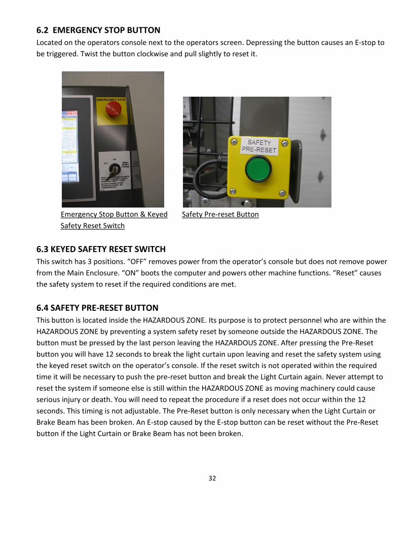
6.2 EMERGENCY STOP BUTTON ................................................................................................................................ 32
6.3 KEYED SAFETY RESET SWITCH .............................................................................................................................. 32
6.4 SAFETY PRE-RESET BUTTON ................................................................................................................................. 32
6.5 BRAKE BEAMS ....................................................................................................................................................... 33
6.6 SAFETY RELAY ...................................................................................................................................................... 33
6.7 SAFETY BRAKE ....................................................................................................................................................... 34
6.8 FUNCTION OF THE SAFETY SYSTEM ..................................................................................................................... 35
6.9 TROUBLESHOOTING THE SAFETY SYSTEM ........................................................................................................... 38
6.9a DIAGNOSING AN E-STOP PROBLEM THAT IS NOT INTERMITTENT ................................................................ 38
6.9b DIAGNOSING AN INTERMITTENT E-STOP ...................................................................................................... 40
7 MAINTENANCE SECTION ............................................................................................................................................ 41
7.1 DAILY .................................................................................................................................................................... 41
7.2 MONTHLY ............................................................................................................................................................ 41
8 ADJUSTMENTS ............................................................................................................................................................ 42
8.1 PICKUP SCREW REPLACEMENT ............................................................................................................................ 42
8.2 DRIVE BELT TENSIONING ..................................................................................................................................... 42
8.3 DRIVE BELT ALIGNMENT ...................................................................................................................................... 43
8.4 PRESSURE SWITCH ADJUSTMENT......................................................................................................................... 44
8.5 PICKUP SCREW DEPTH SETTING .......................................................................................................................... 45
8.6 ALIGNING THE LIGHT CURTAIN SENSOR ............................................................................................................... 45
8.7 ALIGNING THE BRAKE BEAMS .............................................................................................................................. 46
8.8 ALIGNING THE LASER ........................................................................................................................................... 46
8.9 SETTING THE LASER OFFSET IN SOFTWARE ......................................................................................................... 47
8.10 GANTRY BRAKE .................................................................................................................................................. 47
8.11 BRAKE PAD REPLACEMENT ................................................................................................................................ 49
9 TROUBLESHOOTING ................................................................................................................................................... 51
10 DETAILED PARTS IDENTIFICATION - WOOD RUNNER ............................................................................................... 55

4
10.1 RUNWAY ASSEMBLY .......................................................................................................................................... 55
10.2 BELT SUPPORT ASSEMBLY ................................................................................................................................. 57
10.3 RUNWAY DRIVE ASSEMBLY ............................................................................................................................... 58
10.4 RUNWAY IDLER ASSEMBLY ................................................................................................................................ 60
10.5 GANTRY ASSEMBLY ............................................................................................................................................ 61
10.6 PICKING HEAD ASSEMBLY .................................................................................................................................. 64
10.7 ELECTRICAL PANEL ASSEMBLY ........................................................................................................................... 68
10.8 GANTRY ENCLOSURE ASSEMBLY ....................................................................................................................... 70
10.9 CONSOLE ASSEMBLY .......................................................................................................................................... 72
10.10 AIR SUPPLY ASSEMBLY ..................................................................................................................................... 75
10.11 GANTRY VALVE ASSEMBLY ............................................................................................................................... 77
10.12 GANTRY BRAKE ASSEMBLY ............................................................................................................................... 79
11 ELECTRICAL DIAGRAMS ............................................................................................................................................ 81
11.1 SYSTEM OVERVIEW............................................................................................................................................ 81
11.2 MAIN ENCLOSURE – LOW VOLTAGE .................................................................................................................. 82
11.3 GANTRY WIRING – LOW VOLTAGE .................................................................................................................... 83
11.4 I/O CHART .......................................................................................................................................................... 84
11.5 INFEED WIRING – LOW VOLTAGE ...................................................................................................................... 85
11.6 OPERATORS CONSOLE ....................................................................................................................................... 86
11.7 MAIN ENCLOSURE – HIGH VOLTAGE ................................................................................................................. 87
11.8 MAIN ENCLOSURE RECEPTACLE WIRING ........................................................................................................... 88
11.9 SAFETY CIRCUIT LAYOUT.................................................................................................................................... 89
11.10 SAFETY CIRCUIT DIAGRAM .............................................................................................................................. 90
11.11 BRAKE SENSOR DIAGNOSIS ............................................................................................................................. 91
12 PNEUMATIC DIAGRAMS ........................................................................................................................................... 92
12.1 SINGLE HEAD GANTRY ....................................................................................................................................... 92
12.2 DOUBLE HEAD GANTRY ..................................................................................................................................... 93
12.3 INFEED DECK ...................................................................................................................................................... 94

5

6
1 WARRANTY
ACER INC warrants the Wood Runner system to be free from defects in material and
workmanship for one year on parts and 30 days on labor from the original installation date
of the system. Expenses for travel or room and board or other incidental expenses to
install replacement parts are not covered under this warranty. Parts will be repaired or
replaced at ACER INC’S discretion. ACER INC. shall not be liable for parts damaged by abuse,
alteration, lack of maintenance, normal wear and tear or use other than as specified in the
Wood Runner owner’s manual. Components not manufactured by ACER INC (computers,
motors etc.) are subject only to the manufacturer’s warranty terms and are not further
warranted by ACER INC.
Warranty claims must be submitted to ACER INC. in writing and must include the machines
serial number and installation date. Parts returned for warranty consideration must be
shipped to ACER INC via prepaid freight. Warranty parts shipped from ACER INC will be
shipped via ground freight. All extra charges for expedited shipping shall be at the
customer’s expense.
ACER INC shall not be liable for any loss of use, loss of profits or damages based upon a
claim for breach of warranty. This warranty shall be in lieu of any other warranty,
expressed or implied, including but not limited to, any implied warranty of fitness for a
particular purpose, all such other warranties being hereby expressly excluded.
7
2 INTRODUCTION
2.1 MACHINE INTRODUCTION
The Wood Runner is a lumber delivery system designed to feed dimensional lumber to a saw or other production process. It has the capacity to dispense boards from multiple units of lumber. Each unit can be of a different size, length or grade. Capacities of the machine are 2 x 3 through 2 x 12 lumber and 6’-20’ in length. Loading of lumber into the system is done by side load. An integrated safety system protects operating personnel from the moving parts of the system. It is imperative that all personnel are trained in the safe operation of the system. This manual is to be used as a training guide for all operators.
2.2 WHO SHOULD USE THIS MANUAL
All personnel that are involved in the installation, operation and maintenance of this equipment should
read and follow the instructions in this manual. All personnel are to be completely familiar with the safe
operation of this equipment. All persons operating this machine are to be 18 years of age or older and
properly trained by the employer.
2.3 PURPOSE OF THIS MANUAL
This manual is a guide to the safe operation, installation, service and parts of this machine. With this manual, one should be able to understand the operation, as well as gain an understanding to allow servicing the machine. Mechanical, pneumatic and electrical layout and implementation are provided to aid in trouble shooting most common problems that may arise.
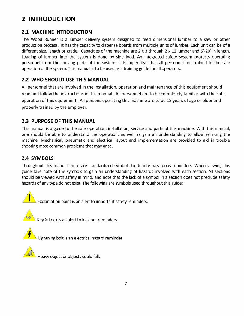
2.4 SYMBOLS
Throughout this manual there are standardized symbols to denote hazardous reminders. When viewing this guide take note of the symbols to gain an understanding of hazards involved with each section. All sections should be viewed with safety in mind, and note that the lack of a symbol in a section does not preclude safety hazards of any type do not exist. The following are symbols used throughout this guide:
Exclamation point is an alert to important safety reminders.
Key & Lock is an alert to lock out reminders.
Lightning bolt is an electrical hazard reminder.
Heavy object or objects could fall.

8
2.5 RELATED DOCUMENTATION
Related documentation includes but is not limited to the following:
1. Safety – The following safety guides should be followed in addition to any safety rules listed in this guide.
OSHA
Local safety standards 2. Mechanical – The following mechanical guides are supplement manuals/guides that take secondary
precedence to specifications list in this manual. See specific part vendor information as required. 3. Pneumatics - See specific part vendor information as required. 4. Electrical – The following electrical guides are supplements and detailed specifications for electrical
equipment used on this machine. See specific part vendor information as required.
2.6 TERMS USED IN THIS MANUAL
Gantry - The traveling part of the machine that scans, picks up and moves lumber to the Infeed
area.
Gantry Brake- A spring applied safety brake to rapidly stop the Gantry movement when an E-stop
device is actuated.
Gantry Brake Valve- A valve mounted on the Gantry near the Brake which holds the brake in the
released position until an E-stop is triggered.
Hazardous Zone - The hazardous zone in which the gantry travels. It is protected by the Perimeter
Guarding and Light Curtain. Personnel must not be in this area during machine operation.
Runway - The guide rail that the Gantry travels along.
Infeed Deck - Receives and stores lumber from the Gantry and feeds it to the saw as necessary. This
component is generally specific to the brand of saw that is being fed.
Operator Console - Contains the main computer and operator interface touch screen. Also contains
the E-stop and Reset Key Switch.
Laser - A specialized sensor that travels with the Gantry. Its purpose is to scan the lumber stacks
and send information to the computer.
Picking Head Assembly - The horizontal bar which moves vertically to pick up lumber from the
stack. The Picking Head is mounted to the Gantry.
Screw Motors - Pneumatically driven motors which rotate the pickup screws.
Pickup Screws - Replaceable screws driven by the Screw Motors for lumber pickup.
E-stop Button - Located on the Operator Console and is used for emergency shutdown only.
Pressing button while Gantry is in motion will apply Safety Brake and stop Gantry very rapidly.
Light Curtain - Safety device with light beams to protect against personnel entering the Hazardous
Zone. Breaking the beam will cause the Gantry to stop rapidly and all other functions to shut down.
Brake Beams - Light beam sensors mounted to the Gantry. Breaking either beam will cause the
Gantry to stop rapidly and all other functions to shut down.

9
Perimeter Guarding - Fencing around the Hazardous Zone to keep personnel out while the machine
is operating.
Lumber Cart - Carts which hold complete units of lumber. They are movable for loading with a
forklift and are guided into position by a floor rail.
Magazine - A stationary rack which holds several individual stacks of lumber. They are hand loaded
and each contains a single vertical stack up to 33 ” high.
Manual Load Position - The rear position on the Magazine designed to hold 1-4 boards. It is used
for low volume boards used in the cutting process.
Main Electrical Enclosure - Contains most of the electrical components for the machine and is
mounted on the end of the Runway. The electrical service for the machine is connected here. The
Main Disconnect is located here and has provisions for locking out the electrical power for service.
See Lockout/Tag-out section.
Lockout/Tag-out - Refers to the OSHA requirement of locking the electrical and pneumatic
disconnects in the Off position before servicing the machine. See the Safety section of this manual
for more information.
I/O Cable - Cables that carry the control signals between various components of the Wood Runner.
Ethernet Cable - Cables that carry the Ethernet communication signal between various components
of the Wood Runner.
Cable Carrier - The rolling carrier on the Runway that allows the cables and hoses to connect to the
moving Gantry.
Air Supply Assembly - The valves, regulator and filter mounted on the end of the Runway. This is
where the shop air supply is connected.
Pressure Switch – Mounted near the Air Supply Assembly. Prevents the WoodRunner from
operating if the air supply pressure is too low.
Home direction – The travel direction of the Gantry as it moves towards the Home Switch and the
Infeed Deck.
Away Direction – The travel direction of the Gantry as it travels away from the Home Switch and
the Infeed Deck.

10
3 SAFE OPERATING PROCEDURES 3.1 HAZARDOUS ZONE
The shaded area in the diagram below is the HAZARDOUS ZONE. This includes the entire area in which the Gantry travels inside a perimeter bounded by the Light Curtain, Perimeter Guard, Runway and Infeed Deck. This area must be totally surrounded by the Perimeter Guard fence and Light Curtain. There must never be personnel inside this area while the system is enabled. Serious injury or death may occur from moving machine parts inside this area. Never reset the safety system or enable the Wood Runner system unless you are sure all personnel are clear of the Hazardous Zone.
NEVER enter the Hazardous Zone while the machine is operating. Serious injury or death could result!
Infeed Deck
Saw
Lumber Cart
Light Curtain
Shaded Area is
Hazardous Zone
Perimeter Guard
Runway

11
NEVER reset the safety system or place the machine in operation when personnel are in the Hazardous Zone.
Serious injury or death could result!
NEVER attempt to defeat any part of the Safety System or remove any part of the Perimeter Guarding. All
access to the Hazardous Area must be through the Light Curtain only. 3.2 SAFETY REQUIREMENTS
The employer shall provide training in the safe operation, maintenance and service of this equipment.
The employer shall monitor the employees operation of the equipment and ensure that safe practices are being followed.
The employer shall establish a program of regular safety and maintenance inspections on this equipment as outlined in the maintenance section of this manual.
The employer shall establish a procedure for the locking out and tagging out of energy sources as required by OSHA.
Safety precautions do not imply or in any way represent an all-inclusive list. The owners and machine
operators are responsible for ensuring that the machine is operated in accordance with all safety
requirements including OSHA (Occupational Safety and Health Act) and ANSI (American National Standards
Institutes) regulations. Other standards and regulation may apply depending on the geographical area.
Because these regulations are subject to change it is impossible to give a reference that will remain
current. It is strongly recommended that current safety regulations be made available and reviewed with
operators on a continual basis. For continued safety information, refer to the specific section on safety.
See the detailed Safety Section later in this manual.
3.3 PRECAUTION The Wood Runner was designed with safety in mind, but as with any machinery, safe operating
procedures must be followed to prevent downtime, machine damage, personal injury or loss of life. It is
the responsibility of all persons involved in the installation and operation of this equipment to
completely understand the safe operating procedures for this machine and to adhere to all safety
precautions in this manual. If unsafe conditions exist, shut down the equipment using the Emergency
Stop Button and Lockout the power sources before servicing system.
READ THE OWNERS MANUAL before installing, loading lumber or operating the machine.
KEEP THE OWNERS MANUAL for future reference and training new operators.
FOLLOW THE OWNERS to insure safe and trouble free operation.
OBEY ALL WARNINGS to prevent injury or loss of life.
WEAR SAFETY GLASSES and steel toe shoes when operating this equipment.
DO NOT WEAR LOOSE FITTING CLOTHING or jewelry which could catch on moving parts. Wear safety equipment as required by employer.
MACHINE OPERATING PERSONNEL must be at least 18 years old and properly trained. It is the employer’s responsibility to see that the operators are properly trained.
DO NOT OPERATE THIS MACHINE if your work ability is impaired by drugs, fatigue, and illness or other causes.
LASER LIGHT is hazardous to the eyes. Never look or stare directly into the beam of the Laser.

12
EMERGENCY STOP BUTTON is located on the front of the Operators Console. It is red in color and should be used if any unsafe conditions are observed.
ACCESS COVERS must be in place at all times to prevent injury. If it is necessary to remove a cover the power must be locked out using proper OSHA methods.
LOCK OUT ELECTRICAL AND PNEUMATIC POWER using proper OSHA procedures before performing any maintenance or adjustments.
PNEUMATIC POWER can remain in hoses after power is removed and escaping air can cause severe injury.
SAFETY DECALS are provided to indicate safety hazards or show safe operating procedures. If they become damaged or missing they must be replaced before operation.
PINCH POINTS exist on all moving machinery. Guards have been provided where possible. Some, because of operating characteristics, cannot be guarded and operators must use caution to avoid injury. Never place hands into or near moving parts or dropping lumber.
VERY IMPORTANT. Never attempt to load or unload a unit or partial unit of lumber that is not securely banded. Falling or tipping lumber could cause injury.
NEVER enter the HAZARDOUS ZONE while the machine is in operation.
NEVER reset or place the machine in operation while personnel are in the HAZARDOUS ZONE.
3.4 LOCKOUT/TAGOUT The following is an outline of the OSHA standard for locking out and tagging out equipment from
hazardous energy sources. A comprehensive copy of this standard is available from OSHA. It is
recommended that the owners and operators obtain this copy and read and understand its contents. A
current copy may be obtained at the regional offices of US Department of Labor, Occupational Safety
and Health Administration.
The purpose of this procedure is to ensure that the equipment is isolated from its power source
and rendered inoperative prior to service or maintenance. Lockout/tag-out devices shall meet
the requirements set forth in the OSHA standards as to durability, standardization, and identity.
A lockout padlock has been provided with the system.
RESPONSIBILITY
This standard requires the employer to establish a program, which includes the following:
Documented energy control procedures.
Employee training program.
Periodic inspections of the use of this procedure. It is the responsibility of the employer to develop a compliant lockout/tag-out program and to
make sure that the program is put into use.
PROCEDURE The following procedure is suggested to comply with this standard:
Shut down the machine by depressing the Emergency Stop button.
Lockout the main power disconnect and pneumatics per OSHA requirements.

13
Tag-out all controls and energy sources which cannot be locked out. All personnel affected must know about and understand all lockout tags.
Verify that all energy sources have been accounted for before performing any maintenance or service work.
When restarting equipment, all lockout/tag-out devices must be removed by the person who installed it.
3.5 EMERGENCY STOP
The E-Stop is the first line of defense to stop a machine from operating. This button halts operation of the
machine and may be used for emergency situations or general shut down. When using the button for non-
emergency shutdowns it is important to wait until the machine is not in a cycling mode as the emergency
brake system will rapidly stop the Gantry if it is in motion. The emergency stop does not remove power
to the machine. Follow lockout/tag-out procedure prior to any service or maintenance.
3.6 SETUP
The following procedures are designed to maximize safety and machine life:
Make sure a properly rated forklift is used to unload your machine and follow all unloading instructions in this guide.
Do not operate machine until all components are located correctly and anchor bolted to the concrete floor.
Before making electrical connections, verify the incoming voltage correctly matches the factory set voltage of the WoodRunner.
3.7 OPERATION
OPERATION OF MACHINE is to be performed by qualified and trained personnel only. Before operating the machine a safety check should be performed to verify the machine is ready for use and is operating correctly.
3.8 SAFETY WHILE SERVICING
ADJUSTMENTS AND SERVICING is to be performed by trained personnel only. A safety check should be performed upon completion of adjustments or servicing to determine that the equipment is operating correctly.
3.9 PNEUMATIC SAFETY
Make sure machine is properly locked out when servicing. When servicing the pneumatic system maintain a clean working area and environment to minimize contamination potential. Keep all spare pneumatic parts in sealed proper containers until needed to minimize contamination.
3.10 ELECTRICAL SAFETY
Make sure machine is properly locked when servicing. Do not attempt to change or modify the
electrical system without first consulting and obtaining approval from a qualified person. Any

14
electrical changes should only be made by a qualified electrician.
Do not override or bypass the safety switches or Light Curtain on this machine.
Do not override or bypass E-Stop
Always have electrical panel doors closed unless being serviced.
3.11 LASER SAFETY
The Wood Runner is equipped with a Laser sensing device. Serious injury to eyes may result from looking directly at the beam.

15
4 INSTALLATION OF EQUIPMENT
4.1 UNLOADING AND INSPECTION
There are restrictions on the lift points of the machine. In order to prevent injury or damage to the machine, use only the methods shown in this manual. It is important that the machine is lifted directly under the frame as shown.
Some parts of the Wood Runner have a high center of gravity while being moved and could present a tipping hazard. Always use caution when unloading. Keep all personnel clear to prevent injury. Damage to airlines and conduits must be avoided while unloading. Never install the Gantry onto the Runway before the Runway is bolted down. The Gantry may tip over causing severe injury or death.
Lift Point on Runway Lift Point on Gantry
4.2 SITE REQUIREMENTS
PNEUMATIC REQUIREMENTS: 100 PSI (max 120PSI) at 20 SCFM (average). Minimum airline feed
size: ½”diameter
ELECTRICAL REQUIREMENTS: 208-230 volts 3Phase 50/60Hz 20 amps or 460 volts 3 phase 50/60 Hz 20 amps. Voltage must be specified at time of order.
ENVIRONMENT: The machine must be installed within a building to provide weather protection.
Intense sunlight, precipitation or windblown dust will cause malfunction and dramatically shorten
the life of the machine. A heated building is required in colder climates. Moisture and condensate

16
in the airlines and valves may freeze and cause machine malfunction if the temperature drops
below freezing. Temperatures above 100 degrees Fahrenheit may shorten the life of electronic
components.
SPACE: Minimum space requirements are shown on the installation drawings provided with your
machine. It is important to allow enough room for access to machine parts for service and loading.
The drawing shows the minimum space - more space generally will allow for more efficient and
safer operation and loading.
REQUIRED FLOOR: The floor must be concrete and a minimum of 4” in thickness to allow the machine to be securely anchored. The floor should be reasonably flat and level. Proper anchoring and leveling is critical for proper machine operation and safety.
4.3 POSITIONING AND ANCHORING
Careful consideration should be given to the site selected for the Wood Runner. Ample room must be provided to facilitate the loading of the machine and for service or maintenance. Once the site is chosen it will be necessary to securely anchor the machine to the floor. Installation drawings are included with the machine. Roughly layout the entire system according to your installation drawings to check for clearances before anchoring. Check to make sure that you have adequate clearance for forklift access and lumber exiting the saw.
Experience has shown that it is best to level and anchor your saw first according to the saw manufacturer’s instructions.
Once the saw is anchored, position the Infeed Deck, level and anchor it. Set the height adjustment on the deck to correspond with the installed height of the saw according to the installation drawings.
Do not place the Gantry onto the Runway until the Runway is properly anchored and leveled.
The Runway should be positioned and anchored after the Infeed Deck. Anchoring and leveling the Runway is critical for safety and machine performance. You must use a 7” long 2x4 block with a 48” level to plumb the guide tubes at each adjusting point. See the installation drawings for the correct procedure.

17
Plumbing the Guide Tubes
Locate and anchor the Operators Console guarding per the drawings.
The Lumber Cart guides and Perimeter Guarding should not be installed until the Gantry is positioned on the Runway. This is covered in the final assembly section.
4.4 FINAL ASSEMBLY
CAUTION - SYSTEM IS INOPERABLE UNLESS THE GANTRY BRAKE SPRING IS UN-CAGED. FOLLOW THE INSTRUCTIONS BELOW AND SEE SECTION 6.7 SAFETY BRAKE
Lift the Gantry carefully from the underside with a forklift high enough that the upper wheels will just slip over the upper track on the Runway. Raising it too high will cause the lower wheels to interfere with the Cable Carrier support channel. Check to see that the brake plunger is properly in place. Drive the forklift towards the Runway at an angle until the wheels are positioned properly. It may be necessary to lift slightly on the outer end of the Gantry while lowering the forklift to engage the wheels. Check to see that the Gantry rolls freely. Check the bottom horizontal surface of the Gantry to see if it is level. Adjust the lower wheel bolts until it is level. Check to see that both wheels are adjusted evenly by trying to turn them opposite directions. If one of the wheels slips (rotates) it should be tightened slightly so that both lower wheels are loaded evenly. Remove the cage bolt from the brake chamber and store it in the holder provided on the side of the chamber. Failure to remove the bolt will disable the brake and may cause machine damage, serious injury or death. You will be instructed to test the proper operation of the brake later in this section and on a daily basis in the maintenance section.
The Lumber Cart guides and Perimeter Guarding should now be positioned and anchored to the floor, using installation drawings provided. It is imperative that the Perimeter Guard is properly installed so that no personnel can enter the Hazardous Zone without passing through the Safety Light Curtain.
Fasten the Cable Carrier to the Gantry with the bolts provided and route the wires and airline through the keepers located on the Gantry.

18
Routing of wires and airline
Next connect the I/O cable and airline to Gantry as shown. Remove the protective tape or sleeve from the Ethernet cable end and route it through the aluminum connector on the Gantry enclosure. This connector must be taken apart to allow the cable to be placed in the slit in the rubber portion. Reassemble the connector and plug the cable into the top Ethernet port. Plugging into the bottom port will not allow the machine to operate.
Ethernet Cable routing – Gantry Enclosure Plug Ethernet cable into the top Ethernet port

19
Plug electrical connector into Gantry Enclosure Connector.
Plugging in the Electrical Connection
Next connect the airline to Gantry as shown, pushing airline into fitting.
Airline connection on Gantry
Loosely connect one end of the drive belt to the Gantry and thread the belt around the drive and idler pulleys. The bottom belt strand will lie on top of the bottom support rollers and the top strand lies on the top support rollers. Tighten the belt so that it has a ¼” sag between the pulleys. Running the belt too tight will shorten the belt and bearing life. A loose belt will jump teeth and cause the Gantry to lose position. See Adjustments in the Maintenance section of this manual for proper belt tightening procedure.

20
Connecting Drive Belt
Install the Picking Head cylinder positioning the ports so that they are closest to the air valve assembly. Leave the bolts loose until the cylinder shaft is connected to the Picking Head. The Picking head must be in the fully raised position before tightening the cylinder. Tightening the cylinder in a lowered position will cause the cylinder to bind. Tighten the shaft nut with a 15/16” socket and a 17mm wrench to hold the shaft. Now secure the cylinder mounting bolts.
Installing Picking Head Cylinder Tightening Cylinder Bolts
Connect the airlines to the cylinder (2) as shown in the picture.

21
Airline Connections on Cylinder
Connect the airline for the Infeed Deck and the I/O cable to the mating connector on the underside of the Main Electrical Enclosure.
Connect the wires for the Infeed Deck motors as shown in the diagram. These are the 4 wires in the flexible conduit. The green ground wire is connected to the ground bar in the lower right corner of the Main Electrical Enclosure. WIRING TO BE DONE BY QUALIFIED ELECTRICIAN.
Connection Location For Infeed Deck Power
Infeed Deck
Circuit
Breaker
Ground Bar

22
Infeed Deck Power Connection
Connect Ethernet and I/O wire between the Operators console and the Main Electrical Enclosure. Both ends of the Ethernet cable route through the same type of aluminum connect that was used on the Gantry. These wires are typically routed through the frame of the Infeed Deck.
Mount the Light Curtain receiver to its bracket near the saw and mount the emitter to the Forklift Guard. The receiver has an 8 pin electrical connector; the emitter has a 5 pin connector. The emitter cable is located in the lower Runway tube and must be fastened along the Perimeter Guard to protect it from damage. The receiver cable originates from the Operators console. The light curtain will need to be aligned after the machine is powered up. See the Startup section.

23
4.5 PNEUMATIC CONNECTIONS
Clean dry air is required for the machines operation. The Wood Runner is provided with a filter and automatic condensate trap in the Air Supply Assembly. A ½” shop air line should be connected to the ½” NPT female port on the Air Supply Assembly. A minimum of 100 PSI and a maximum of 120 PSI are required. Average air consumption is less than 10 SCFM but momentary usage will be much higher. Malfunction or slow operation will result from using a feed line smaller than ½”.
4.6 ELECTRICAL CONNECTIONS
All wiring must be done by a qualified electrician in accordance with local and national electrical
codes. The machine is designed to operate on 3 phase, 50/60 Hz, 208/230 or 460 volt power
depending on the WoodRunner’s factory wiring. Changing the voltage in the field will require
factory assistance. An extra knockout hole is provided from the factory in the enclosure for
incoming power. Drilling or punching of any other holes in the enclosure must be done carefully.
Any drill shavings or other particles of metal which enter the electrical components will seriously
damage or destroy them and will not be covered under warranty. Cover all components before
drilling and vacuum out the shavings from the enclosure. Never use an air hose as you may blow
particles into the electrical components.
Your machine should be factory wired to your voltage. If the voltage needs to be changed it will be
necessary to consult the factory for correct parts and diagrams. Motor wiring, overloads and circuit
breakers are different for high and low voltage systems. Software settings for the servo amp will also need
to be changed. The panel will also require new voltage stickers and labels.
A ground lug is provided in the panel for the incoming ground wire. Grounding is very important for safety
and also for correct operation of the electronic devices.
After the electrician has completed the wiring connections it will necessary to power up the machine and
check the rotational direction of the Infeed Deck motors. This is covered in the next section. Should the
motors run backwards it will be necessary for the electrician to switch two of the incoming power leads.
Disconnect and Ground Lug
Ground Lug
Disconnect

24
4.7 Gantry Brake
Never attempt to operate the Wood Runner system unless the Gantry brake system is operational and has been tested for safe operation. Never remove or disable the brake system. Serious machine damage, injury or death may occur.
Cut and remove the zip tie strap or shrink wrap holding the Gantry Brake plunger onto the Gantry. There will be a slight amount of spring pressure.
The brake release tool is pre-installed in the rear brake chamber for shipping and must be removed to allow the
gantry brake to operate.
To remove, turn the hex nut counter-clockwise using a 3/4” wrench. Remove the nuts and washer. Now remove
the threaded release tool stud by rotating it ¼ turn to the counterclockwise to unlock it. There will be a slight
resistance. Remove the tool from the hole, insert the release tool into the mounting hole on the outside of the
brake chamber and fasten in place with the washer and nuts.
Note: Once this is done, the Gantry cannot be moved until the wiring and pneumatics are functional.

25
5 OPERATING INSTRUCTIONS
You will need to familiarize yourself with the different screens available on the Wood Runner computer.
Navigation to the various screens is selected by buttons on the Main screen.
5.1 MACHINE STARTUP
Check to see that you have completed all of the connections properly as outlined above and make
sure all personnel are clear of the Hazardous Zone. See Safe Operating Procedures section earlier
in manual.
Check to see that Gantry Brake has been released as described in Section 4.
Depress the E-stop button on the Operator Console to insure that the machine does not start.
Turn the Main Disconnect to the ON position.
Turn the safety lockout valve to the ON position. This is located on the Air Supply Assembly. Check
the main pressure gauge for proper 90 psi pressure setting and adjust the regulator if necessary.
Turn the key switch on the Operators Console to the ON position and wait for the Computer to
display the Main screen.
Adjust the Light Curtain alignment as covered in section 8.6 of this manual. A Light Curtain that is
not aligned properly will prevent the safety system from resetting and the machine from operating.
Enter the Hazardous zone and press the Pre-Reset button. You will now have 8 seconds to break
the Light Curtain beam and reset the system using the reset key switch. See section 6.4 for a
description of the Pre-Reset Button operation.
Turn the key switch to the Reset position momentarily and the Enable screen should be shown. If a
Reset does not occur recheck the Light Curtain and Brake Beam adjustment. Refer to section 6 on
the Safety system.
Read and follow the instructions on the Enable Screen and then touch the Enable button. Enabling
the system will put the machine in operational mode. This should power up the servomotor for the
Gantry and energize the air system. The Picking Head and Screw Motor cylinders will retract to
their upper position. The Enable screen will change to the Main screen if the machine successfully
enables. See the Troubleshooting Section if the enable fails.

26
Check the Main screen for a low air warning in the upper left corner. See the Troubleshooting
section if you have a warning.
Check to make sure that the Gantry is free from obstructions. Press the Home button on the screen
and wait for the machine to travel to the end of the Runway and stop. See the Operating
Instructions section under Homing for a detailed explanation.
The Machine is now ready to operate.
LOADING LUMBER
Depress the E-stop button and leave it depressed when loading lumber into the system.
Always center the lumber carefully on the carts. Off center lumber may cause problems with the
lifting mechanism and may interfere with the travel of the Gantry. Put a mark on the lumber stack
to help the forklift operator line the lumber up with the cart.
Place the lumber on the cart so that the stack is tight to the vertical support with no gap. The
lumber should be in an orderly stack and parallel to the carts length.
The lumber stack must sit firmly against the bottom cart supports. Remove any bottom cross
spacers that will interfere with the cart supports before loading.
Cut and remove all banding and bottom spacers after the lumber is loaded
Lumber must also be centered when loaded into a magazine. Marks place on the floor for the end
of the lumber can help center the different lengths.
Never mix different sizes or lengths of lumber on one cart.
Push the cart all the way in to the stop when replacing it. This centers the cart with the Gantry.

27
5.2 MAIN SCREEN
This is the screen that displays when the machine is powered up. During operation the lumber sequence is
shown as well as the status of the Infeed Deck. Homing can be done from this screen.
Main Screen

28
5.3 MANUAL CONTROLS SCREEN
Troubleshooting and testing can be done from this screen. You will be able to see all of the inputs from the
safety system, sensors and buttons. Outputs can be controlled from here. The outputs include the air
valves, motors and Gantry movement. Use Caution when controlling outputs to avoid machine damage
due to interference of the controlled movements.
Manual Screen

29
5.4 SETTINGS SCREEN
Lumber sizes and types are assigned here to the various Lumber Carts and Magazines in the Wood Runner
system.
Settings Screen

30
5.5 HOMING
Homing the machine allows the Gantry to determine its exact position on the Runway. There is a homing
switch located on the Runway close to the Main Electrical Panel. When the machine is instructed to home
the Gantry will move slowly in the Home direction until the switch is energized and then reverse direction
until the switch is de-energized. If the homing switch is already energized when the homing command is
given, the Gantry will move in the Away direction until the switch is de-energized. Homing is required
whenever the computer is powered down and after certain faults occur. The Home button will display as
red when homing is required. If the machine will not Home itself check to see that the machine is enabled.
An improperly adjusted Head up switch will also not allow the machine to Home.
Homing Switch Location Homing Switch Location – Close up
5.6 SCANNING
Scanning refers to the process of locating the position and shape of all lumber stacks in the system.
Scanning finds the position of the next board to be picked from each lumber stack and can identify empty
stacks. The data from the laser and the Gantry encoder are both used in the scanning process. A lumber
scan must be performed whenever the machine is restarted after being powered off. It is also a continuous
process whenever the Gantry is traveling. When the e-stop button is pushed or the Light Curtain is broken
you will be given the option of rescanning. If the lumber stacks have not been disturbed you may choose
not to scan.
Homing Switch

31
6 SAFETY SYSTEM DESCRIPTION AND TROUBLESHOOTING
The Wood Runner system is equipped with several safety components to insure the safety of the operator
and other personnel. These components make up the Safety system and work together to shut down the
Wood Runner system when a dangerous condition exists.
NEVER modify, tamper with or remove any part of this safety system as severe injury or death may occur.
Test the function daily before operating the machine. Do not operate the machine if any part of the safety
system is not functioning correctly. Have the safety system repaired and tested before placing it back in
service.
Components of the Safety system are:
6.1 LIGHT CURTAIN
A special safety sensor containing multiple beams of invisible light which cause an E-stop to be triggered
when the beams are broken by a person or object. The Light Curtain is made up of two parts, the
Transmitter and the Receiver. The Transmitter sends out the light beams and the Receiver receives them.
Any interruption in one of the beams will trigger the Receiver. The Light Curtain detects when a person
enters the Hazardous Zone through the open side of the Perimeter Guarding and shuts the system down.
Light Curtain Receiver Light Curtain Transmitter
32
6.2 EMERGENCY STOP BUTTON
Located on the operators console next to the operators screen. Depressing the button causes an E-stop to
be triggered. Twist the button clockwise and pull slightly to reset it.
Emergency Stop Button & Keyed Safety Pre-reset Button
Safety Reset Switch
6.3 KEYED SAFETY RESET SWITCH
This switch has 3 positions. “OFF” removes power from the operator’s console but does not remove power
from the Main Enclosure. “ON” boots the computer and powers other machine functions. “Reset” causes
the safety system to reset if the required conditions are met.
6.4 SAFETY PRE-RESET BUTTON
This button is located inside the HAZARDOUS ZONE. Its purpose is to protect personnel who are within the
HAZARDOUS ZONE by preventing a system safety reset by someone outside the HAZARDOUS ZONE. The
button must be pressed by the last person leaving the HAZARDOUS ZONE. After pressing the Pre-Reset
button you will have 12 seconds to break the light curtain upon leaving and reset the safety system using
the keyed reset switch on the operator’s console. If the reset switch is not operated within the required
time it will be necessary to push the pre-reset button and break the Light Curtain again. Never attempt to
reset the system if someone else is still within the HAZARDOUS ZONE as moving machinery could cause
serious injury or death. You will need to repeat the procedure if a reset does not occur within the 12
seconds. This timing is not adjustable. The Pre-Reset button is only necessary when the Light Curtain or
Brake Beam has been broken. An E-stop caused by the E-stop button can be reset without the Pre-Reset
button if the Light Curtain or Brake Beam has not been broken.

33
6.5 BRAKE BEAMS
These are single light beam sensors protecting both sides of the Gantry. Breaking either beam will cause an
E-stop condition. The primary purpose is to rapidly stop the Gantry if something is in the path of travel.
The sensors consist of two parts, the Emitter and Receiver. The sensor located closest to the Infeed Deck is
the Home Brake Beam and the other sensor is the Away Brake Beam. Each sensor has a corresponding
Input on the Input/Output Module in the Gantry enclosure. These Inputs are equipped with a status LED.
The LED is illuminated if the beam sensor is not blocked. Blocking the sensor or a beam out of alignment
will cause the relay LED to go off and cause an E-stop condition.
Home and Away Brake Beam Receivers Home and Away Brake Beam Emitters
6.6 SAFETY RELAY
A Safety Relay located in the Main Electrical Enclosure which monitors the status of the Light Curtain, E-
stop button and Obstruction Sensors. When any of these are triggered by the operator or an unsafe
condition the relay shuts the Wood Runner system down and reports this to the PC. The PC can then
display information on the screen relating to the source of the E-stop condition. The Safety Relay is
equipped with 3 LED’s to help troubleshoot any problems. See section 6 for Safety Relay information.
Safety Relay
Safety Relay
LED lights

34
6.7 SAFETY BRAKE
The Gantry safety brake stops the Gantry rapidly when an E-stop condition occurs. The brake is applied by
a spring and is held in the released position by air pressure provided through the Brake Valve. An E-stop
condition causes the air pressure in the Brake chamber to be released through the Brake Valve. Releasing
the air pressure allows the spring in the chamber to rapidly apply the brake. This brake is meant for
emergency use only and is not meant to be used for normal stopping. A properly maintained Safety Brake
will stop the Gantry very quickly in an emergency. The Manual screen has a recorder which displays the
Gantry stopping distance for each Emergency stop system actuation. A properly operating brake system
will stop the Gantry in less than 20 inches from full speed. A stopping distance longer than 20 inches
indicates a problem with the brake system and presents a safety hazard. A screen warning will appear
when this happens. It is very important to identify and repair the cause of the problem immediately to
prevent injury or death.
Brake Chamber Safety Brake
Safety Brake Valve

35
6.8 FUNCTION OF THE SAFETY SYSTEM
The safety system can be triggered (E-stopped) by any one of four separate devices. These devices are the
Light Curtain, E-stop Button, Home Brake Beam and the Away Brake Beam. The E-stop Button and Light
Curtain are two channel devices meaning that two separate electrical paths are monitored in each.
Breaking the flow of current in either path will cause an E-stop condition to occur. A broken wire or other
failed component in either path will also cause an E-stop. An E-stop condition causes power to be removed
from the air system dump valve and servo amp inputs as well as the Infeed deck motors to stop the
system.
The Brake Beam sensors supply power to Inputs 165 and 166 causing the control system to output power
on Output 202. The current to power the Light Curtain originates from Output 202 and passes through
both channels of this device and the E-stop Button to power the Safety Relay inputs. Breaking either of the
Brake Beams or the Light Curtain beam or pushing the E-stop Button will cause the Safety Relay to open
dumping the system air supply and shutting down the Gantry and Infeed Deck motors. Breaking any of the
Beams will require a special reset procedure which is different from the reset procedure required when
pushing the E-stop button. See section 6 .
The status of the overall Safety System can be viewed on the Main screen on the PC. Here you can view
the actual inputs from each of the safety devices and the reset status of the Safety relay. The cause of the
last E-stop can be viewed here even if it was an intermittent problem. This is explained in the next section.
Shown here is a diagram of the Wood Runner safety system. The main components and the
interconnections between them and the system PC are detailed. This is not meant to be a wiring diagram;
it is designed to show the theory only. The diagram shows the dual path that must be maintained through
the various safety input devices and the inputs from the devices to the system PC.

36

37

38
6.9 TROUBLESHOOTING THE SAFETY SYSTEM
Most problems that are likely to occur can be readily diagnosed using the messages on the Main screen,
the input status on the Main screen and the LED indicating lights on the Safety Relay in the Operators
Enclosure.
The most common problem you may encounter is that the Wood Runner system cannot be enabled or is
disabled by a random E-stop not caused by the operator. The random E-stop could be of an intermittent
nature and would be hard to diagnose without understanding the Safety system.
Main screen - The text at the top of the screen will show the cause of an E-stop condition as long as the
condition still exists
Safety Relay - Three LED’s are located on the Safety relay and are very useful for troubleshooting. The
Safety Relay is located in the Operators console. See the diagrams below for an explanation.
6.9a DIAGNOSING AN E-STOP PROBLEM THAT IS NOT INTERMITTENT
The E-stop cause is continually displayed at the top of the Main screen. Check the message at the top of
the screen to determine what device is causing the E-stop. Use the guide below to narrow down the
source of the problem.

39
E-stop button - Check to see that it is not depressed. Check the wiring to the E-stop button for damage or
disconnection. Replace the entire switch or both contact blocks on the switch if no wiring problem is
found.
Light Curtain - First verify that both the Receiver and the Emitter have green LED lights lit. Check the wiring
for damage if one of the lights is not lit. Output 202 is feeding power to the receiver so it should be
checked to see that the 202 LED is lit in the Operators Console. If the red LED on the Receiver (unit closest
to operator’s console) is lit the Light Curtain is not aligned properly. An amber LED indicates that the Light
Curtain alignment is poor or the lens is dirty. Re-align both the Emitter and Receiver as covered in the
Maintenance section under Adjustments. Replace the Light Curtain if the problem cannot be solved with
alignment or wiring repair.
Either Brake Beam - Verify that the green power LED is lit on both the Receiver and Emitter of the
Obstruction sensor. The Emitters are located on the end of the Gantry and each will have two green LEDs
lit when power is present. The Receivers are located closest to the Runway and each will have one green
LED lit when power is present. The amber LED on the receiver should be lit if the beam is not broken. Re-
align the sensors as shown in the Maintenance section under adjustments if the amber LED is not lit. Check
the green LED on the corresponding input in the Gantry Electrical Enclosure. The input LED should always
be lit when the amber LED is lit on the receiver. A damaged or broken wire is the most likely cause if it is
not lit.

40
6.9b DIAGNOSING AN INTERMITTENT E-STOP
No message will be retained at the top of the Main screen if the E-stop cause is intermittent. Navigate to
the Manual screen and view the inputs for the Light Curtain, E-stop Button and Obstruction sensors. The
input box will be red for the input that caused the last E-stop condition. This information will let you focus
on where the problem occurred. Most intermittent E-stop conditions will be caused by the Obstruction
sensors or the Light Curtain being out of alignment usually due to being bumped. A damaged cable or a
worn cable in the Cable Carrier connected to the Gantry could also be responsible.

41
7 MAINTENANCE SECTION
Proper maintenance will keep your Wood Runner working efficiently and minimize any downtime.
Maintenance procedures are simple and require very little time.
7.1 DAILY
Inspect all safety guarding to make sure it is in place and fasteners are tight. Repair if
problems are found.
Check the safety system for proper function - blocking the Light Curtain or pushing the E-
stop button should cause the air system to exhaust. Repair any problem found before
operating.
Test the Gantry brake system for proper operation by breaking the Light Curtain beam
when the Gantry is moving. The stopping distance recorded during the stop is displayed on
the manual screen. This distance should be 20” or less. Repair the brake system
immediately if the value is over 20”. Failure to do so may result in machine damage or injury
or death.
Replace pickup screws before starting a work shift.
Check for loose fasteners, wires or airlines.
Listen for air leaks while the system is energized.
Any unusual noises while operating should be investigated immediately.
Remove any debris that has accumulated in the cable carrier channel or on the Runway
wheel path or other parts of the machine.
Inspect Gantry Brake Pad for pad material wear. Replace brake pad when worn .
7.2 MONTHLY
Check for proper drive belt tension and re-tension if necessary.
Tighten any loose fasteners.
Reposition or replace any dangling or chafing wires or airlines.
Inspect Gantry wheels for smooth operation.
42
8 ADJUSTMENTS
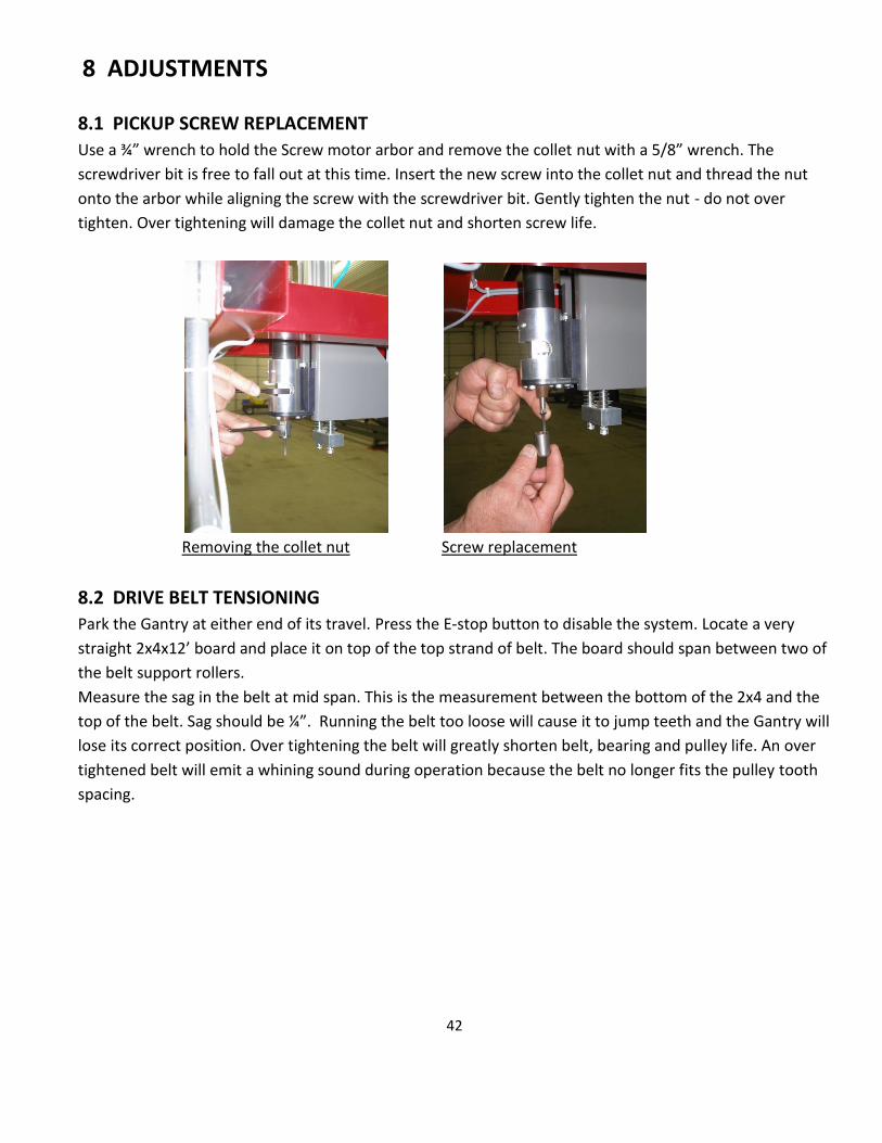
8.1 PICKUP SCREW REPLACEMENT
Use a ¾” wrench to hold the Screw motor arbor and remove the collet nut with a 5/8” wrench. The
screwdriver bit is free to fall out at this time. Insert the new screw into the collet nut and thread the nut
onto the arbor while aligning the screw with the screwdriver bit. Gently tighten the nut - do not over
tighten. Over tightening will damage the collet nut and shorten screw life.
Removing the collet nut Screw replacement
8.2 DRIVE BELT TENSIONING
Park the Gantry at either end of its travel. Press the E-stop button to disable the system. Locate a very
straight 2x4x12’ board and place it on top of the top strand of belt. The board should span between two of
the belt support rollers. Measure the sag in the belt at mid span. This is the measurement between the bottom of the 2x4 and the
top of the belt. Sag should be ¼”. Running the belt too loose will cause it to jump teeth and the Gantry will
lose its correct position. Over tightening the belt will greatly shorten belt, bearing and pulley life. An over
tightened belt will emit a whining sound during operation because the belt no longer fits the pulley tooth
spacing.

43
Drive Belt Tensioning – Board location Drive Belt Tensioning – ¼” sag
8.3 DRIVE BELT ALIGNMENT
The pulleys must be properly aligned so that the belt tracks correctly on the pulleys. Poor tracking will
damage the belt or pulley flange. This procedure is done from outside the Hazardous Zone (SEE SAFETY
SECTION) while the Gantry is in Auto Cycle mode. Start the Gantry in Auto Cycle mode from the MANUAL
screen after checking that all personnel are clear of the Hazardous Zone. Observe the belt running on the
pulleys to see if it is crowding into one of the side flanges. A light crowding is acceptable. Do not loosen the two bolts closest to the pulley. Adjust the alignment by
reaching through the window and loosening the two bolts closest to you ¼ turn with a 9/16” wrench.
Between these two bolts are two socket set screws. Tighten (clockwise) each of these set screws ¼ turn if
the belt is crowding the inside (closest to Runway) flange. Loosen the set screws ¼ turn if the belt is
crowding the outside flange. Retighten the 9/16” bolts and watch the belt while the Gantry makes several
cycles. Re-adjust as necessary. Repeat this procedure on the opposite end of the Runway.
Drive Belt Alignment

44
8.4 PRESSURE SWITCH ADJUSTMENT
The purpose of the pressure switch is to provide a warning and prevent operation when the air pressure to
the system is below the required pressure. Low pressure will not allow the safety brake to release and will
impair other functions. The pressure switch is provided with an LED light that illuminates if the pressure is
high enough for system operation and an output to the Wood Runner’s computer. Setting the pressure
switch is a simple push button operation which is detailed below.
1. Enable the system to allow air to reach the pressure switch. A disabled or E-stopped system will not
allow the adjustment
2. Turn the main regulator control knob counter-clockwise to lower the system pressure to 75 PSI.
3. Using a pen or pencil push and hold the set button on the pressure sensor until it flashes
continuously.
4. Let off the button and reset the main regulator to 90 PSI by turning the knob clock-wise to increase
the pressure to 90 PSI.
Pushing in set button on Pressure Switch

45
8.5 PICKUP SCREW DEPTH SETTING
The depth that the Pickup screws thread into the board is adjustable. Depth is set at ¾” engagement at the
factory. A switch on the Pressure Pad is set to trip at the correct depth and shut the screw motor off. See
the instructions and picture below for the adjustment procedure.
1. Measure the overall length of the screw extending below the collet nut and record.
2. Pick up a board with the machine using the Manual screen.
3. E-stop the system before entering the Hazardous Zone.
4. Measure the distance from the top of the board to the bottom of the collet nut and subtract this
from the previous measurement. The difference is the current engagement depth. Loosen the
locknut and thread the trigger screw clockwise to increase the engagement depth or clock-wise to
decrease.
5. Re-tighten the locknut and retest the engagement depth.
Screw Depth
8.6 ALIGNING THE LIGHT CURTAIN SENSOR
A misaligned Light Curtain may cause random E-stops or prevent the system from operating altogether. Use the following procedure to correctly set the alignment. The green LED on the receiver (sensor closest to the Operators console) is steadily lit when the alignment is satisfactory. Amber or red LED’s on the Receiver indicate an improperly aligned Light Curtain. A green LED on the Emitter end of the Light Curtain shows only that power is present. The Emitter is equipped a special Laser alignment system to help align it to the Receiver.
1. Depress the E-stop button with the system powered up. Do not enable the system.
2. Locate the small magnet that was shipped with WoodRunner. This is used to turn on the Laser alignment beams on the Light Curtain Emitter. Pass the magnet over the bottom portion of the front face of the Emitter as shown in the picture. This can take a few seconds and the 3 Laser beams will illuminate. Use the top and bottom bracket adjustments to aim the laser beams at the Receiver windows. They do not have to be perfect- just close is fine. Tighten the Emitter adjustment screws.

46
3. Loosen the adjustment screws for the Receiver and rotate and tip it until the green LED is lit. Sweep it left to right and up and down to locate the midpoint of the “on” (green LED) before tightening the adjustment screws. Amber or red LED’s indicate improper alignment.
8.7 ALIGNING THE BRAKE BEAMS
Misaligned sensors may cause random E-stop occurrences or may prevent the operation of the machine
altogether. Use the following procedure to properly align the obstruction sensors.
1. Depress the E-stop button with the system powered up. Do not enable the system.
2. Starting with the Emitter (the part of the sensor located at the outer end of the Gantry) loosen
vertical and horizontal the mounting clamps slightly to allow the sensor to be rotated. You will
need another person watch the Receiver (located closest to Runway) for the amber LED to light.
This LED will be lit if the sensor is aligned but it does not represent the optimal alignment. Sweep
the Emitter to the left until the amber LED is off and then back to the right until the sensor goes off
again. Set the sensor at the approximate center point between the left and right points and tighten
the horizontal clamp. Repeat this procedure for the vertical axis of the Emitter.
3. Loosen the Receiver clamps slightly and sweep the sensor horizontally to find the midpoint and
then tighten the clamp. Repeat this for the vertical axis.
8.8 ALIGNING THE LASER It is important that the Laser sensor beam is aligned parallel to the Picking head vertical travel. A misaligned Laser
will cause the Pickup Screws to land off center on the board when the lumber stack is low. Follow this procedure to
correct the alignment.
1. Energize the system to raise the Picking Head is at its highest level. Press the E-stop button before entering the
Hazardous Zone. 2. Hold a tape measure against the side of the horizontal bar in the Picking Head and position it so that the Laser dot
shows up on the blade of the tape measure. Record this reading. 3. Leave the Hazardous Zone and enable the system. Using the head down button on the Manual screen lower the
Picking Head to its lowest position. Again check the measurement as in step 2 and record. 4. If the measurements from step 2 and step 3 are more than 1/8” different you will need to re-align the Laser.
Remove the protective guard from the Laser to access the adjusting screws. Slightly loosen the top screw and tighten the bottom screw if the measurement in step 3 was the greater of the two. Reverse the adjustment if step 2 measurement was the greater of the two. Adjust the Laser until both measurements are within 1/8’. Record the final measurement for setting the Laser offset on the Settings screen.
5. Replace the protective cover and tighten the screws securely.

47
8.9 SETTING THE LASER OFFSET IN SOFTWARE The horizontal offset of the Laser from the centerline of the Pickup screws is adjustable in the software. The actual
value measured and recorded in the above section 8.8 was measured to the closest side of the Picking Head
horizontal bar. It will be necessary to add 1 ¼” to this measurement to correspond to the center of the picking
screws. The resulting value must be recorded correctly in software to allow the Pickup screws to land on the center
of the board.
8.10 GANTRY BRAKE DANGER - Do Not attempt to take the brake chamber apart. Never loosen either of the band clamps on the brake
chamber. The brake chamber contains a large spring which is compressed and could cause severe injury or death to
anyone servicing the brake system. Replace the entire brake chamber as a unit if service is required.
To Remove the Brake Chamber:
DANGER- Do Not attempt to remove the brake chamber from the Gantry without caging the spring as outlined
below. Failure to comply may result in severe injury or death.
Follow all safety precautions found in this manual and on the brake chamber.
Disconnect the airline between the brake and the valve located on top of the gantry cross member.
Release Tool & Airline Location Install washer and tighten nuts as shown
Remove brake release tool from its storage area located on the side of the brake. Install washer and tighten
two nuts together as shown.
Brake Airline
Release Tool

48
Inserting tool into the hole; aligning tabs with slots Brake Chamber end with slots
Insert release tool into the hole in the back of the brake chamber by aligning the tabs on the tool with the
slots on the brake chamber.
Turning release tool clockwise Tighten nut until spring is compressed
Applying slight inward pressure, turn the release tool clockwise ¼ turn with 11/16” wrench until it locks in.
Remove one of the nuts and tighten the other nut to fully compress the internal spring. You will feel a
moderate resistance while the spring is being compressed. The nut should be tightened several turns until it
bottoms out and increased resistance is felt. DO NOT OVER TIGHTEN! The spring is now caged and it is safe
to remove the chamber.

49
Locknut and Pad Locations Loosen the locknut on brake chamber
Loosen the locknut on the brake chamber and unscrew the brake chamber by turning it counter-clockwise.
The chamber should unscrew easily if the chamber spring is properly compressed. CAUTION! If it is difficult
to turn, stop and check that the chamber spring has been properly caged.
When reinstalling the chamber screw the chamber clockwise until it bottoms out lightly (the brake pad is
now forced against the Runway rail) and then back it off 1 to 1 1/2 turns (counterclockwise) to provide
running clearance and allow access the storage area for the release tool. Tighten the locknut and reinstall
the airline.
Remove the release tool and replace in in its storage area.
Test the brake function as shown in the Safety section of this manual.
8.11 BRAKE PAD REPLACEMENT To Replace the Brake Pad Material:
Follow the same steps listed above for caging the brake chamber spring but do not remove the chamber.
Disconnect drive belt from the gantry.
Lift the Gantry vertically off the runway (about 6 inches) until you can remove the brake plunger.
Remove the socket head screw and replace brake pad material.
Reinstall the plunger.
Remove the airline from the Brake Chamber,
Loosen the Brake Chamber locknut an turn the Brake Chamber several turns counterclockwise to provide
more clearance for the new pad.
Lower the Gantry onto the rail.
Rotate the Brake Chamber clockwise until you feel the brake pad contact the Runway. Back it off ½-3/4 turn
for clearance and relock the locknut.
Remove release tool and replace in the storage area.
Locknut
Brake Pad
Material

50
Reinstall the drive belt and tension it correctly.
Test the brake function as shown in the Safety section of this manual.

51
9 TROUBLESHOOTING
See Section 6 SAFETY SYSTEM for troubleshooting information for the safety devices and safety system.
SYMPTOM PROBLEM CAUSE/SOLUTION SYSTEM WILL NOT POWER UP NO LIGHTS IN MAIN ENCLOSURE
NO INCOMING POWER OR DISCONNECT SHUT OFF CIRCUIT BREAKER FOR POWER SUPPLY TRIPPED FAULTY POWER SUPPLY-GREEN LED NOT ON
HAVE ELECTRICIAN CHECK INCOMING POWER RESET CIRCUIT BREAKER REPLACE POWER SUPPLY
OPERATORS CONSOLE PC WILL NOT START BUT MAIN ENCLOSURE HAS LIGHTS
PROBLEM WITH I/O CABLE TO CONSOLE FAULTY KEY SWITCH FAULTY PC
PLUG CABLE IN OR REPLACE CABLE REPLACE KEY SWITCH REPLACE OR REPAIR PC
SYSTEM ENABLES AND GANTRY MOVES BUT INPUTS AND OUTPUTS ON GANTRY NOT WORKING
UNPLUGGED OR FAULTY ETHERNET CABLE FROM MAIN ENCLOSURE TO GANTRY
PLUG CABLE IN OR REPLACE CABLE
SYSTEM ENABLES BUT GANTRY WILL NOT HOME
HEAD UP SWITCH NOT TRIGGERED UNPLUGGED OR FAULTY ETHERNET CABLE BRAKE NOT RELEASED SERVOAMP CIRCUIT BREAKER TRIPPED SERVOMOTOR OR SERVOAMP PROBLEM
CHECK INPUT 151 FOR LED AND REPAIR OR ADJUST SWITCH PLUG IN OR REPLACE CABLE CHECK AIR SUPPLY AND REPAIR OR REPLACE BRAKE RESET BREAKER CONSULT SERVICE TECHNICIAN
SYSTEM WILL NOT ENABLE SYSTEM HAS E-STOP CONDITION LOW AIR PRESSURE NOTIFICATION SHOWING ON SCREEN
SEE SECTION ON E-STOP CONDITION CHECK INCOMING AIR SUPPLY CHANGE AIR FILTER LOCKOUT VALVE CLOSED FAULTY DUMP VALVE-REPLACE

52
E-STOP CONDITION WILL NOT RESET- SEE SAFETY SYSTEM SECTION OF MANUAL FOR DETAILED EXPLANATION OF SAFETY SYSTEM
LIGHT CURTAIN NOT ALIGNED E-STOP SWITCH PUSHED IN OR FAULTY BRAKE BEAM NOT ALIGNED FAULTY CABLE ON LIGHT CURTAIN OR BRAKE BEAM I/O CABLE UNPLUGGED OR FAULTY TO OPERATORS CONSOLE OR GANTRY FAULTY SAFETY RELAY
SEE LIGHT CURTAIN ALIGNMENT IN SAFETY SYSTEM SECTION PULL OUT SWITCH OR REPLACE SEE BRAKE BEAM ALIGNMENT IN SAFETY SYSTEM SECTION REPAIR CABLE PLUG CABLE IN OR REPLACE CABLE REPLACE
LOW AIR PRESSURE NOTIFICATION ON SCREEN BUT INCOMING AIR PRESSURE CORRECT - SEE AIR SUPPLY ASSEMBLY SECTION OF MANUAL
SAFETY LOCKOUT VALVE CLOSED DUMP VALVE NOT OPENING FILTER PLUGGED PRESSURE SWITCH PROBLEM
OPEN VALVE CABLE TO DUMP VALVE UNPLUGGED. FAULTY CABLE OR FAULTY DUMP VALVE REPLACE FILTER CABLE UNPLUGGED. FAULTY PRESSURE SWITCH OR FAULTY CABLE
ONE OF THE AIR VALVES WILL NOT OPERATE EVEN FROM MANUAL SCREEN
CABLE PROBLEM VALVE PROBLEM
CABLE UNPLUGGED OR FAULTY VALVE FAULTY- REPLACE
INFEED DECK MOTORS WILL NOT OPERATE EVEN FROM MANUAL SCREEN
MOTOR CIRCUIT BREAKER. TRIPPED OVERLOAD TRIPPED FAULTY MOTOR CONTACTOR WIRING PROBLEM TO MOTOR FAULTY MOTOR
CHECK FOR JAM CONDITION OR GEARBOX PROBLEM RESET OVERLOAD REPLACE CONTACTOR REPAIR REPLACE MOTOR

53
GANTRY HITS END STOP WHEN HOMING
PROBLEM WITH HOME SWITCH
HOME SWITCH GAP SET IMPROPERLY- RESET TO 1/16” CABLE UNPLUGGED OR FAULTY FAULTY SWITCH
PICKUP SCREWS CONSISTENTLY NOT CENTERED ON BOARD
LASER ALIGNMENT RE-ALIGN LASER WITH LOAD BAR- COVERED IN ADJUSTMENT SECTION OF MANUAL
LUMBER PILES NOT SHOWN IN SCAN
LASER OR INPUT MODULE PROBLEM LASER DOT NOT VISIBLE LASER DOT VISIBLE
CABLE UNPLUGGED OR FAULTY CABLE OR FAULTY LASER FAULTY LASER- REPLACE FAULTY INPUT
NOISY DRIVE BELT BELT TOO TIGHT PULLEYS OUT OF ALIGNMENT
RE-TENSION BELT-SEE ADJUSTMENT SECTION REALIGN PULLEYS-SEE ADJUSTMENT SECTION
GANTRY DOES NOT STOP RAPIDLY WHEN LIGHT CURTAIN IS BROKEN BUT BRAKE VALVE ACUATES
BRAKE PADS WORN OR BRAKE ASSEMBLY FAULTY
REPLACE OR REPAIR
AIR DUMP VALVE DOES NOT DRAIN AIR WHEN E-STOP OR LIGHT CURTAIN ACTIVATED
STICKING DUMP VALVE REPLACE
PICKUP SCREW NOT THREADING INTO BOARD FAR ENOUGH
PRESSURE PAD SWITCH OUT OF ADJUSTMENT WRONG SCREW LENGTH
SEE ADJUSTMENT SECTION OF MANUAL
PICKUP SCREW MOTOR DOES NOT SHUT OFF AFTER THREADING INTO BOARD
PROBLEM WITH PRESSURE PAD SWITCH
FAULTY SWITCH, CABLE OR SWITCH OUT OF ADJUSTMENT
SCREW MOTOR WILL NOT RUN EVEN FROM MANUAL SCREEN
PRESSURE PAD STICKING AND KEEPING SWITCH ACTIVATED AIR VALVE STICKING AIR VALVE CABLE PROBLEM SCREW MOTOR PROBLEM
REPAIR REPLACE REPLACE OR REPAIR REPLACE OR REPAIR

54
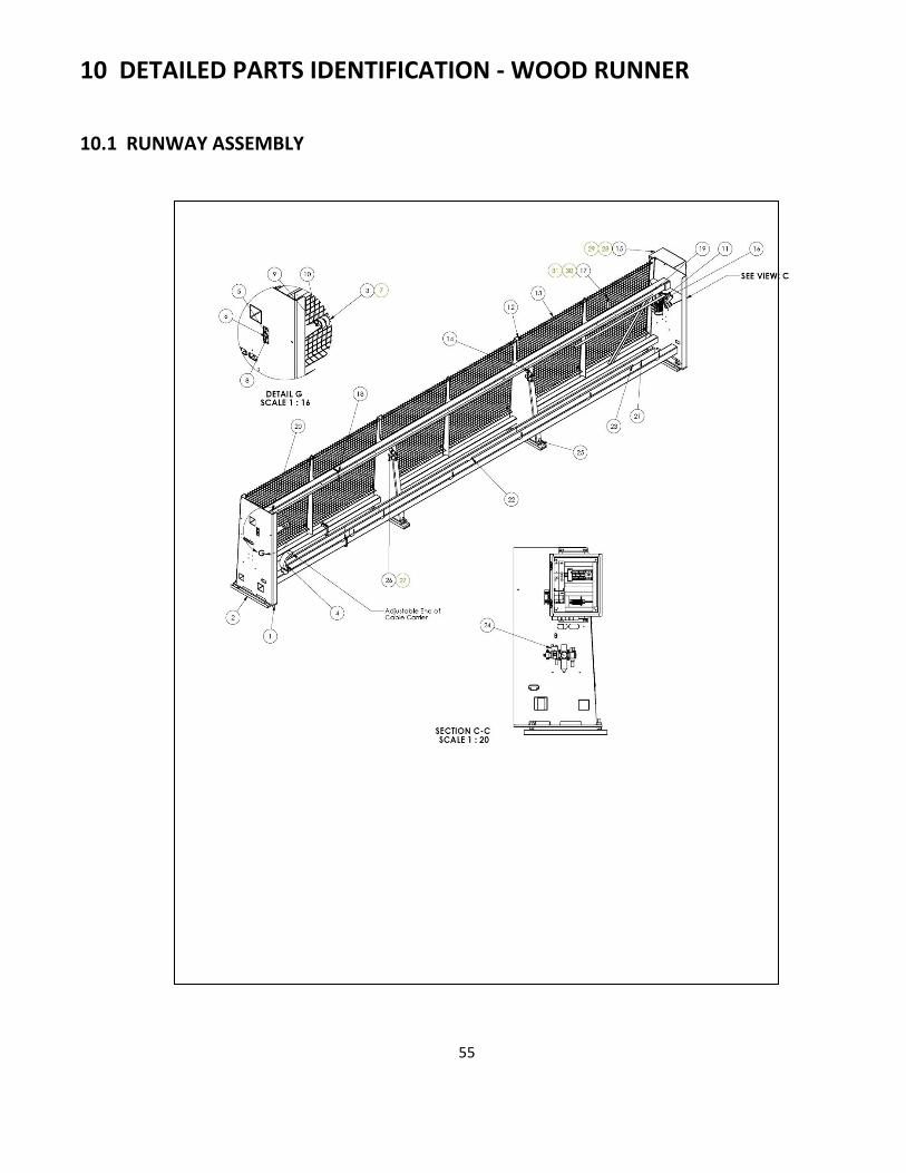
55
10 DETAILED PARTS IDENTIFICATION - WOOD RUNNER
10.1 RUNWAY ASSEMBLY

56
RUNWAY ASSEMBLY
No. Description Part Number
1 Runway
2 Runway Foot 3 Bump stop PC5019
4 Cable Carrier – 30 ft. PC5041-30 Cable Carrier – 40 ft. PC5041-40 Cable Carrier – 60 ft. PC5041-60
5 Runway Idler Assembly SA5042 6 3/8 Flat Washer
7 ½ Flat Washer
8 3/8-16 X 1-1/4 Hex Bolt
9 ½-13 X 1-1/2 Hex Bolt
10 ½-13 Hex Nut
11 Timing Belt – 30 ft. PC5027-30 Timing Belt – 40 ft. PC5027-40
Timing Belt – 60 ft. PC5027-60
12 Panel Tubing
13 Wire Panel Assembly 56 x 54 SA5134
14 Belt Support Assembly SA5075
15 Enclosure Assembly SA5094
16 Runway Drive Assembly SA5109
17 Bracket Home Sensor MC5553
18 Brake Plate – 144 MC5531
19 Brake Plate - 130 MC5631
20 Brake Plate - 59 MC5632
21 Glide Stand-off MC5449
22 Track Glide Bar – Front MC5626
23 Track Glide Bar – Rear MC5625
24 Air Supply Assembly SA5228
25 1-8 Hex Nut
26 3/8-16 X 1 Hex Bolt
27 3/8-16 Hex Nut
28 5/16-18 X 1 Hex Bolt
29 5/16-18 Hex Nut
30 ¼ Flat Washer
31 ¼-20 X 1 Hex Bolt

57
10.2 BELT SUPPORT ASSEMBLY
BELT SUPPORT ASSEMBLY
No. Description Part Number
1 Roller Mount Bracket MC5378
2 Belt Roller MC5118
3 Idler Spacer MC5503
4 ½ Narrow Flat Washer
5 ½-13 X 3 Hex Bolt
6 ½-13 Hex Nut

58
10.3 RUNWAY DRIVE ASSEMBLY

59
RUNWAY DRIVE ASSEMBLY
No. Description Part Number
1 Mount Plate Gearbox MC5447
2 Motor w/Resolver EP5129
3 Shaft MC5448
4 Timing Belt Pulley – Drive MC5141
5 Power Lock Bushing PC5024
6 Key - Metric PC5102
7 5/16 Flat Washer
8 3/8 Flat Washer
9 5/16 Lock Washer
10 ½ Lock Washer ½-13 X 1 Hex Bolt
11 3/8 Lock Washer
12 M8 X 30 Metric Hex Bolt
13 3/8-16 X 1 Hex Head Bolt
14 ½-13 X 1 Hex Head Bolt
15 ½ Wide Flat Washer
16 3/8-16 X 1 Socket Head Set Screw

60
10.4 RUNWAY IDLER ASSEMBLY
RUNWAY IDLER ASSEMBLY
No. Description Part Number
1 Mount Plate Idler MC5091
2 Timing Belt Pulley – Idler MC5143
3 Bearing – Wheel PC5001
4 Shaft Idler – Runway MC5113
5 7/8 Shaft Collar PC5021
6 3/8-16 X 1 Socket Head Set Screw
7 ¾-10 Nylock Nut

61
10.5 GANTRY ASSEMBLY
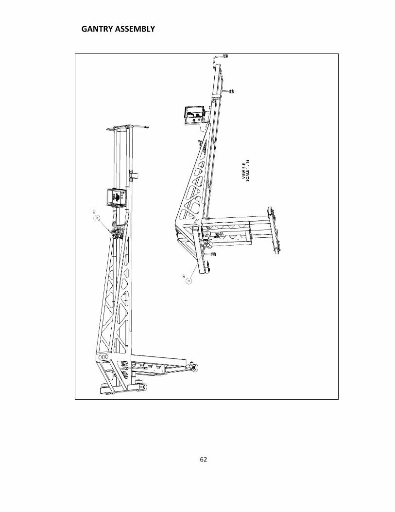
62
GANTRY ASSEMBLY

63
GANTRY ASSEMBLY
No. Description Part Number
1 Gantry
2 Gantry Brake Assembly SA5074
3 Lower Wheel Link SA5011
4 Wheel MC5056
5 Wheel Bushing MC5293
6 Clamp Body PC5055
7 Sensor Arm MC5291
8 3/8 Flat Washer
9 1/2 Flat Washer
10 Alum Shaft Collar PC5057
11 Laser w/Cable EP5000
12 Laser Adaptor MC5450
13 Laser Adaptor Mount Plate MC5451
14 Laser Cover MC5452
15 Enclosure Assembly SA5108
16 Sensor Mount MC5295
17 Gantry Valve Assembly SA5236
18 Worm Drive Hose Clamp PC5075
19 Thru Beam Emitter EP5059
20 Thru Beam Receiver EP5058
21 3/8-16 X 6-1/2Hex Bolt
22 3/8-16 Hex Nut
23 ½-13 Hex Nut
24 ½-13 X 4-1/2 Hex Bolt
25 3/8-16 X 4-1/2 Hex Bolt
26 Jumbo Flat Washer 2 OD X 3/8 ID
27 Marshmallow Spring - Polyurethane
28 Belt Tension Block MC5122
29 Belt Clamp Plate MC5152
30 Belt Adjustment Rod MC5121

64
10.6 PICKING HEAD ASSEMBLY

65
PICKING HEAD ASSEMBLY

66
PICKING HEAD ASSEMBLY
No. Description Part Number
1 Motor Plate MC5137
2 Slide Block MC5135
3 Screw Cylinder PP5028
4 18MM Prox Switch EP5005
5 18MM Prox Nut
6 Screw Bearing PC5025
7 3/8-16 Hex Nut
8 ¼-20 Hex Nut
9 ¼ Lock Washer
10 10-24 X 5/8 Socket Head Cap Screw
11 3/8 Flat Washer
12 5/16 Flat Washer
13 Slide Washer MC5156
14 Sensor Rod MC5150
15 Prox Bracket MC5153
16 Picking Head Cylinder PP5006
17 Top Yoke MC5155
18 Cable Carrier PC5035
19 Screw Housing MC5220
20 Air Motor PP5025
21 Arbor MC5224
22 Compression Spring .48 OD PC5040
23 5/16 Elevator Bolt PC5014
24 Load Bar SA5020
25 Compression Spring .60 Od PC5031
26 Straight Connector 3/8 NPT X 3/8 Tube PP5079
27 Muffler G1/8 PP5085
28 Straight Connector 1/8 NPT X ¼ Tube PP5049
29 Screw Pad Assembly SA5050
30 Guide Tube – Grooved MC5296
31 Vertical Guide Bushing MC5297
32 Pipe Nipple PP5096
33 Quick Exhaust PP5094
34 Orifice Top MC5298
35 Orifice Bottom MC5299
36 Driver Bit PC5062
37 Screw PC5061
38 Collet Nut MC5301
39 Wire Retaining Ring MC5356
40 Head Clamp MC5557
41 Retaining Ring PC5059

67
42 Straight Connector 1/8 G X ¼ Tube PP5048
43 Cylinder Mount Tube – Offset MC5563
44 Head Mount Bar MC5556
45 5/8 Flat Washer
46 3/8 SAE Flat Washer
47 ¼-20 X 3-1/4 Hex Bolt
48 3/8-16 X 3-1/2 Hex Bolt
49 5/16-18 X 5 Hex Bolt
50 5/16-18 X 1/2 Socket Head Set Screw
51 Valve PP5140
52 90 Deg. Elbow 3/8 NPT X ¼ Tube PP5054
53 Silencer PP5122
54 Metric Bolt M8 X 25
55 5/16-18 Hex Nut
56 90 Deg. Elbow 3/8 NPT X 3/8 Tube PP5077
57 Set Screw Collar 3/8 PC5101
58 Tube Y ½ X 3/8 X 3/8 PP5144
59 Tube Y 3/8 X ¼ X 1/4 PP5056
60 ½-20 Hex Jam Nut
61 10-32 X ½ Socket Head Cap Screw
62 M6 X 25 Metric Bolt
63 M6 X 90 Metric Bolt
64 5/8-18 Hex Nut
65 ¼-20 X 3/8 Socket Head Set Screw
66 5/16-18 X 2-1/2 Hex Bolt
67 M16 X 2 Hex Jam Nut
68 Bump Stop MC5281
69 Union Y ¼ Tube PP5126

68
10.7 ELECTRICAL PANEL ASSEMBLY

69
ELECTRICAL PANEL ASSEMBLY
No. Description Part Number
1 Back Panel EP5117
2 Wire Way – 17-3/4”
3 Wire Way – 10-3/4”
4 Wire Way – 4-1/4”
5 Din Rail – 6”
6 Din Rail – 8-1/4”
7 Power Supply EP5045
8 2 Pole Breaker – Power Supply EP5046
9 3 Pole Breaker – Servo Amp EP5047
10 Disconnect Switch EP5118
11 Power Supply EP5119
12 Single Inverter EP5120
13 2 Conductor Wago Block – Gray EP1211
14 End Stop Wago EP1210
15 2 Conductor Wago Block – Blue EP1213
16 2 Conductor Wago Block – Orange EP1214
17 Jumper EP1215
18 Wago Fuse Terminal EP5143
19 Wago Gray End Barrier EP5157
20 Fuse 5 amp EP5144
21 Ground Bar EP5158

70
10.8 GANTRY ENCLOSURE ASSEMBLY

71
GANTRY ENCLOSURE ASSEMBLY
No. Description Part Number
1 Back Panel MC5550
2 Din Rail – 5-1/2”
3 End Stop Wago EP1210
4 2 Conductor Wago Block – Gray EP1211
5 2 Conductor Wago Block – Orange EP1214
6 2 Conductor Barrier Wago – Gray EP1213
7 End Barrier - Orange EP1212
8 Ethercat Bus Coupler EP5127
9 Jumper EP1215
10 Analog Input EP5138
11 Digital Input EP5125
12 Digital Output EP5126

72
10.9 CONSOLE ASSEMBLY

73
CONSOLE ASSEMBLY

74
CONSOLE ASSEMBLY
No. Description Part Number
1 Console
2 Din Rail 18”
3 End Stop Wago EP1210
4 2 Conductor Wago Block – Gray EP1211
5 2 Conductor Barrier Wago – Orange EP1212
6 2 Conductor Wago Block – Orange EP1214
7 Jumper EP1215
8 Relay Socket EP5087
9 2 Conductor Wago Block – Blue EP1213
10 Relay EP5135
11 Bushing MC5577
12 Ethercat Bus Coupler EP5127
13 Analog Input EP5128
14 Digital Input EP5125
15 Digital Output EP5126
16 Relay with LED EP5010
17 Wire Way – 18-1/4”
18 Wire Way – 7”
19 Wire Way – 6”
20 Converter 24 to 12 EP5159
21 Draw Latch PC5098
22 M5 X .8 Flanged Lock Nut
23 Touch Screen EP5139
24 Gas Spring PC5100
25 DVID to VGA Converter EP5150
26 3 Position Switch EP5054
27 Red Twist E-Stop EP5055

75
10.10 AIR SUPPLY ASSEMBLY

76
AIR SUPPLY ASSEMBLY
No. Description Part Number
1 Filter Regulator – Auto Drain PP5156
2 T-Bracket PP5159
3 Shutoff/Relief Valve PP5162
4 Adaptor Plate PP5157
5 Liquid Filled Gauge PP5155
6 Soft Start Dump Valve PP5161
7 U-Bracket PP5160
8 Pneumatic Distribution Block PP5163
9 Silencer PP5152
10 Hex Bushing PP5164
11 Straight Connector 1/2 NPT X 3/8 Tube PP5166
12 Straight Connector ¼ NPT X ¼ Tube PP5043
13 Straight Connector 1/2 NPT X 1/2 Tube PP5165
14 Mount Bracket PP5023
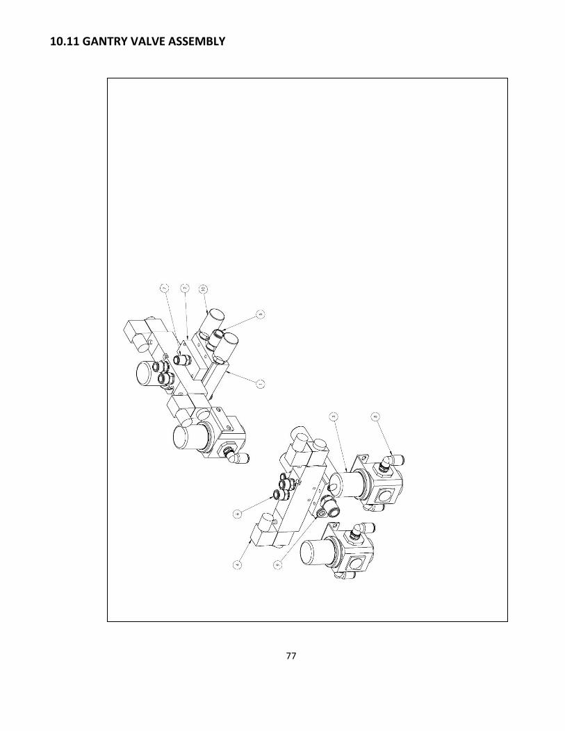
77
10.11 GANTRY VALVE ASSEMBLY

78
GANTRY VALVE ASSEMBLY
No. Description Part Number
1 Valve Manifold PP5137
2 Port Adaptor MC5648
3 Regulator – Gauge & Bracket PP5093
4 Valve PP5140
5 Straight Connector 3/8 NPT X ½ Tube PP5052
6 Straight Connector 3/8 NPT X 3/8 Tube PP5079
7 Straight Connector ¼ G X 3/8 Tube PP5045
8 90° Connector ¼ NPT X 3/8 Tube PP5047
9 Hex Head Pipe Plug PP5127
10 Silencer PP5129

79
10.12 GANTRY BRAKE ASSEMBLY

80
GANTRY BRAKE ASSEMBLY
No. Description Part Number
1 Brake Backer MC5368
2 Brake Pad MC5371
3 Brake Shaft MC5446
4 Shoulder Screw ½ X 1-1/4
5 Compression Spring PC5076
6 Brake Chamber PC5054
7 Valve PP5098
8 Straight Connector 3/8 NPT x 3/8 Tube PP5079
9 Silencer PP5129
10 Reducing Tee ½ x 3/8 x ½ PP5099

81
11 ELECTRICAL DIAGRAMS
11.1 SYSTEM OVERVIEW

82
11.2 MAIN ENCLOSURE – LOW VOLTAGE

83
11.3 GANTRY WIRING – LOW VOLTAGE

84
11.4 I/O CHART

85
11.5 INFEED WIRING – LOW VOLTAGE
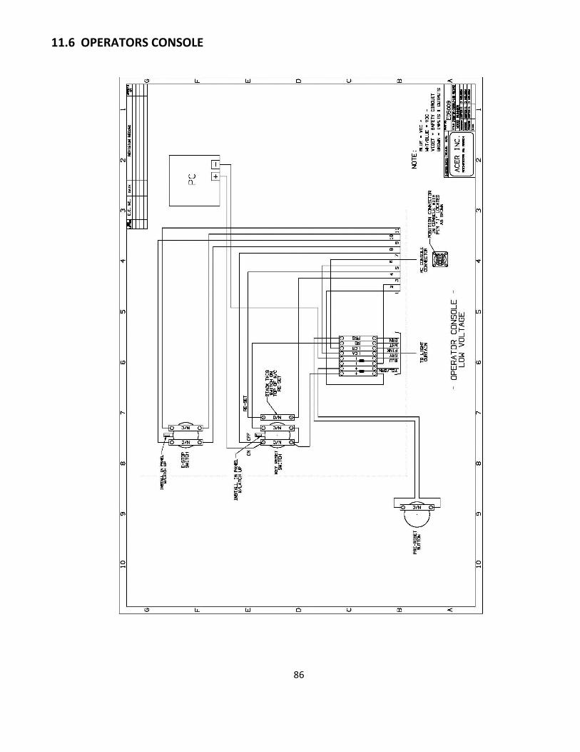
86
11.6 OPERATORS CONSOLE

87
11.7 MAIN ENCLOSURE – HIGH VOLTAGE

88
11.8 MAIN ENCLOSURE RECEPTACLE WIRING

89
11.9 SAFETY CIRCUIT LAYOUT

90
11.10 SAFETY CIRCUIT DIAGRAM

91
11.11 BRAKE SENSOR DIAGNOSIS

92
12 PNEUMATIC DIAGRAMS
12.1 SINGLE HEAD GANTRY

93
12.2 DOUBLE HEAD GANTRY

94
12.3 INFEED DECK