Embed Size (px)
Citation preview
WOOD I-BEAMS AND ZIG-ZAG DECKING FROM ROUNDWOOD
INNOVATIVE AND EFFICIENT USE OF ROUNDWOOD FOR STRUCTURAL SECTIONS THROUGH SUSTAINABLE DESIGN
Brad Miller, HDR Engineering, Inc.
Missoula, Montana
www.hdrinc.com
(406) 532-2200
Brad Miller – HDR Engineering, Inc. Missoula, Montana [email protected] (406)532-2200 1
June 16, 2011
Brad Miller P.E. is a Senior Bridge Project Manager for HDR Engineering, Inc. in Missoula,
Montana.
Tom Gorman Ph.D, P.E. is Professor of Forest Products at the University of Idaho in Moscow, Idaho
Brad Miller – HDR Engineering, Inc. Missoula, Montana [email protected] (406)532-2200 2
OVERVIEW
Harvests to control pine bark beetle infestations in the Intermountain West may increase the
availability and utilization of material that could be used for innovative and sustainably designed
locally manufactured new products. Trees with low commercial timber value may also be suitable.
Two concepts with potential for use of this material are solid Wood I-beams and “ZIG-ZAG decking.”
These structural products should be well suited for pedestrian and short span road bridges and other
beam and decking applications in building construction.
Wood I-Beams are made from roundwood by flattening or dapping the top and sides, sawing the
resulting cant into 3-pieces, and assembling/gluing them into more structurally efficient Wood I-
Beams. These compare in strength to similar depth glulam beams. Testing performed by the
University of Idaho produced high strengths and favorable results.
“ZIG-ZAG decking” (and planks or beams) may be made from small diameter roundwood by sawing
or milling each round piece into two identical trapezoidal sections similar to a hexagon cut in half.
By alternating the orientation of the trapezoidal sections, these components can be assembled into a
continuous “ZIG-ZAG deck” or into rectangular sections by cutting one of the pieces in half and
using each piece at opposite sides of the section.
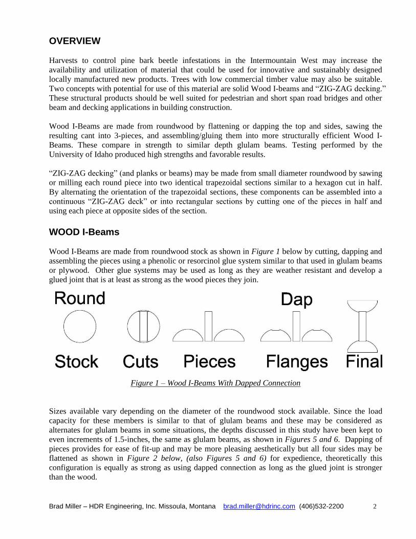
WOOD I-Beams Wood I-Beams are made from roundwood stock as shown in Figure 1 below by cutting, dapping and
assembling the pieces using a phenolic or resorcinol glue system similar to that used in glulam beams
or plywood. Other glue systems may be used as long as they are weather resistant and develop a
glued joint that is at least as strong as the wood pieces they join.
Figure 1 – Wood I-Beams With Dapped Connection
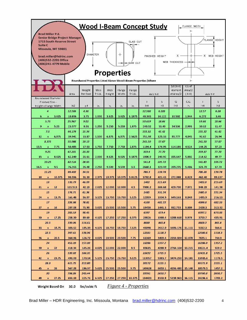
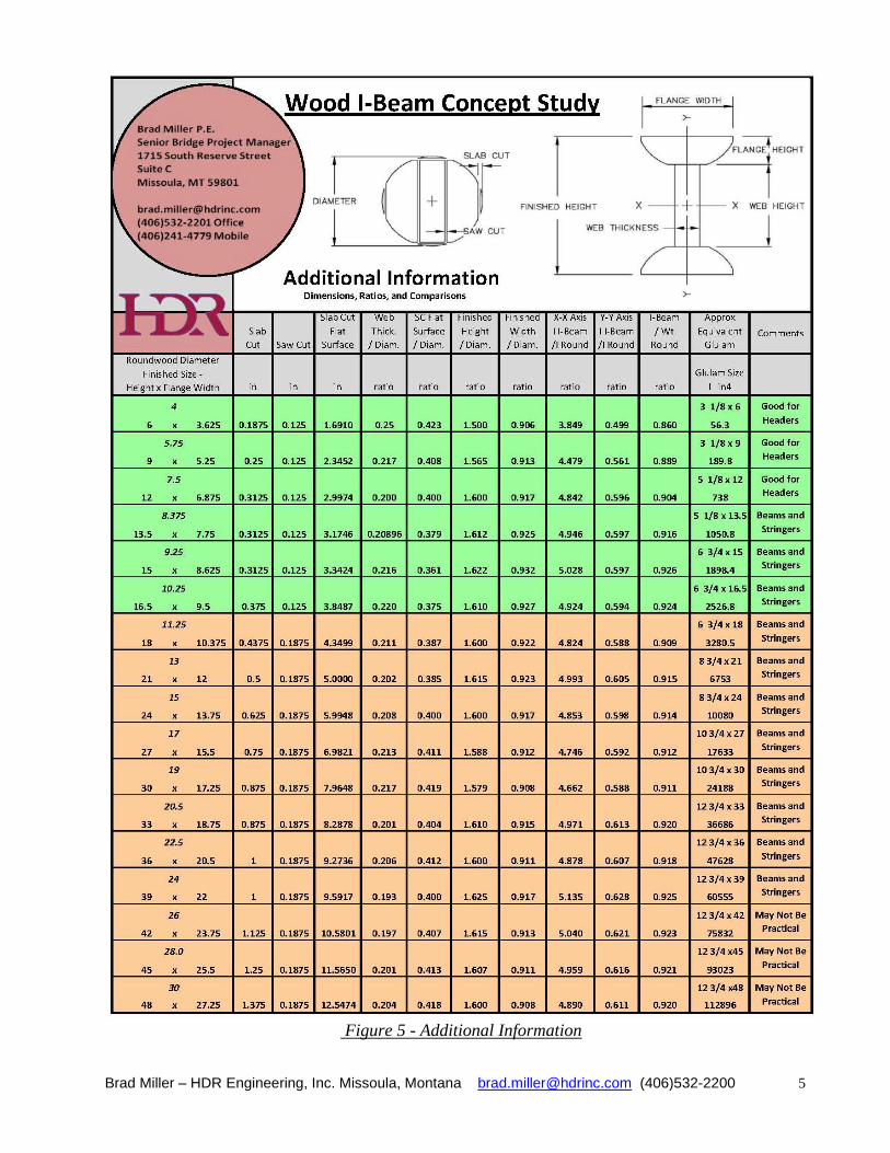
Sizes available vary depending on the diameter of the roundwood stock available. Since the load
capacity for these members is similar to that of glulam beams and these may be considered as
alternates for glulam beams in some situations, the depths discussed in this study have been kept to
even increments of 1.5-inches, the same as glulam beams, as shown in Figures 5 and 6. Dapping of
pieces provides for ease of fit-up and may be more pleasing aesthetically but all four sides may be
flattened as shown in Figure 2 below, (also Figures 5 and 6) for expedience, theoretically this
configuration is equally as strong as using dapped connection as long as the glued joint is stronger
than the wood.

Brad Miller – HDR Engineering, Inc. Missoula, Montana [email protected] (406)532-2200 3
Figure 2 – Wood I-Beams with Non Dapped Connection, U of I Test Section
The conversion from roundwood to Wood I-Beams uses over 90 percent of the roundwood material
for an ideal round member. For a tapered member, see Figure 2, this is slightly less than 90 percent.
The bark may be left on as shown in Figure 2, or the round stock may be turned before making the
Wood I-Beams. In either case the section properties are very similar for each depth of member. The
strength increases nearly five times when converting roundwood to Wood I-Beams, effectively
doubling the allowable span length. See Figures 4 and 5 below for properties and additional
information including comparisons between Wood I-Beams and the parent roundwood.
Manufacture of Wood I-Beams would be an excellent use of bug-killed or low value trees and would
be suitable for pedestrian bridges, short span road bridges and for use in buildings for beams and
headers.
Figure 3 – Possible Bridge Section
Brad Miller – HDR Engineering, Inc. Missoula, Montana [email protected] (406)532-2200 4
Figure 4 - Properties
Brad Miller – HDR Engineering, Inc. Missoula, Montana [email protected] (406)532-2200 5
Figure 5 - Additional Information
Brad Miller – HDR Engineering, Inc. Missoula, Montana [email protected] (406)532-2200 6
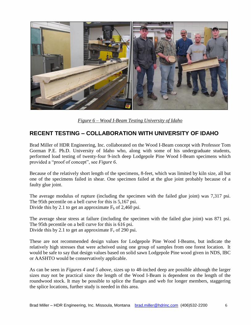
Figure 6 – Wood I-Beam Testing University of Idaho
RECENT TESTING – COLLABORATION WITH UNIVERSITY OF IDAHO
Brad Miller of HDR Engineering, Inc. collaborated on the Wood I-Beam concept with Professor Tom
Gorman P.E. Ph.D. University of Idaho who, along with some of his undergraduate students,
performed load testing of twenty-four 9-inch deep Lodgepole Pine Wood I-Beam specimens which
provided a “proof of concept”, see Figure 6.
Because of the relatively short length of the specimens, 8-feet, which was limited by kiln size, all but
one of the specimens failed in shear. One specimen failed at the glue joint probably because of a
faulty glue joint.
The average modulus of rupture (including the specimen with the failed glue joint) was 7,317 psi.
The 95th pecentile on a bell curve for this is 5,167 psi.
Divide this by 2.1 to get an approximate Fb of 2,460 psi.
The average shear stress at failure (including the specimen with the failed glue joint) was 871 psi.
The 95th pecentile on a bell curve for this is 616 psi.
Divide this by 2.1 to get an approximate Fv of 290 psi.
These are not recommended design values for Lodgepole Pine Wood I-Beams, but indicate the
relatively high stresses that were acheived using one group of samples from one forest location. It
would be safe to say that design values based on solid sawn Lodgepole Pine wood given in NDS, IBC
or AASHTO would be conservatively applicable.
As can be seen in Figures 4 and 5 above, sizes up to 48-inched deep are possible although the larger
sizes may not be practical since the length of the Wood I-Beam is dependent on the length of the
roundwood stock. It may be possible to splice the flanges and web for longer members, staggering
the splice locations, further study is needed in this area.
Brad Miller – HDR Engineering, Inc. Missoula, Montana [email protected] (406)532-2200 7
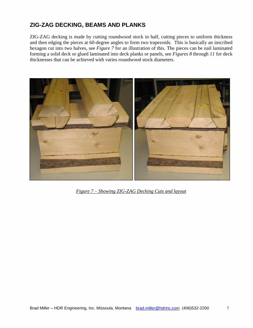
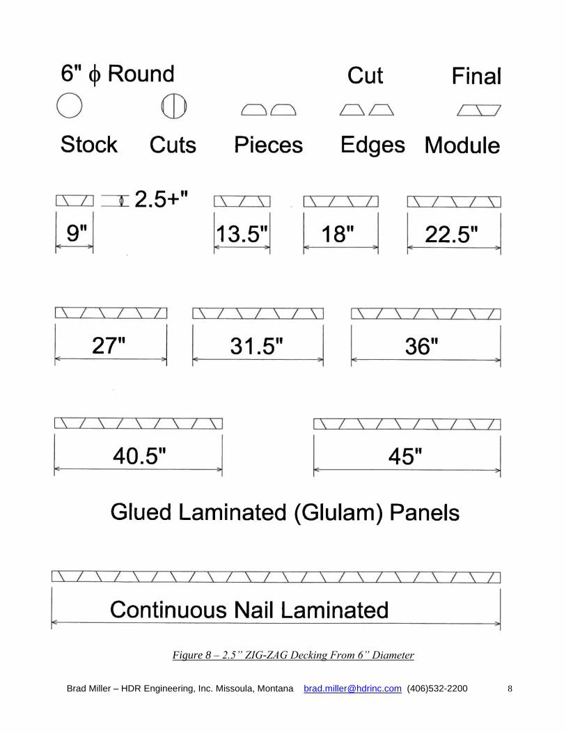
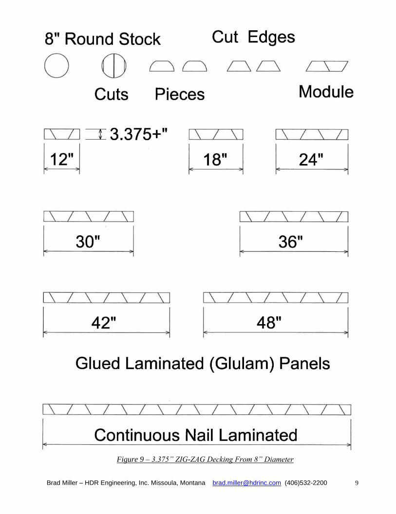
ZIG-ZAG DECKING, BEAMS AND PLANKS ZIG-ZAG decking is made by cutting roundwood stock in half, cutting pieces to uniform thickness
and then edging the pieces at 60-degree angles to form two trapezoids. This is basically an inscribed
hexagon cut into two halves, see Figure 7 for an illustration of this. The pieces can be nail laminated
forming a solid deck or glued laminated into deck planks or panels, see Figures 8 through 11 for deck
thicknesses that can be achieved with varies roundwood stock diameters.
Figure 7 – Showing ZIG-ZAG Decking Cuts and layout
Brad Miller – HDR Engineering, Inc. Missoula, Montana [email protected] (406)532-2200 8
Figure 8 – 2.5” ZIG-ZAG Decking From 6” Diameter
Brad Miller – HDR Engineering, Inc. Missoula, Montana [email protected] (406)532-2200 9
Figure 9 – 3.375” ZIG-ZAG Decking From 8” Diameter

Brad Miller – HDR Engineering, Inc. Missoula, Montana [email protected] (406)532-2200 10
Figure 10 – 4.25” ZIG-ZAG Decking From 10” Diameter

Brad Miller – HDR Engineering, Inc. Missoula, Montana [email protected] (406)532-2200 11
Figure 11 – 5.125” ZIG-ZAG Decking From 12” Diameter
Brad Miller – HDR Engineering, Inc. Missoula, Montana [email protected] (406)532-2200 12
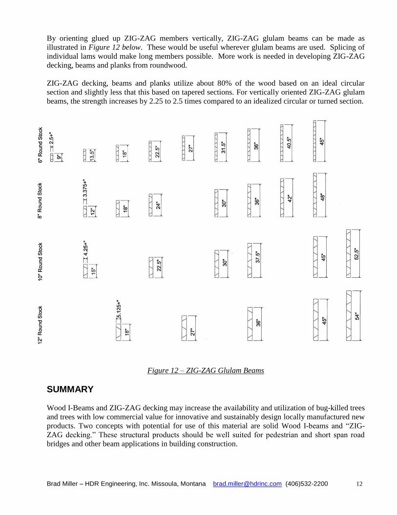
By orienting glued up ZIG-ZAG members vertically, ZIG-ZAG glulam beams can be made as
illustrated in Figure 12 below. These would be useful wherever glulam beams are used. Splicing of
individual lams would make long members possible. More work is needed in developing ZIG-ZAG
decking, beams and planks from roundwood.
ZIG-ZAG decking, beams and planks utilize about 80% of the wood based on an ideal circular
section and slightly less that this based on tapered sections. For vertically oriented ZIG-ZAG glulam
beams, the strength increases by 2.25 to 2.5 times compared to an idealized circular or turned section.
Figure 12 – ZIG-ZAG Glulam Beams
SUMMARY Wood I-Beams and ZIG-ZAG decking may increase the availability and utilization of bug-killed trees
and trees with low commercial value for innovative and sustainably design locally manufactured new
products. Two concepts with potential for use of this material are solid Wood I-beams and “ZIG-
ZAG decking.” These structural products should be well suited for pedestrian and short span road
bridges and other beam applications in building construction.


![[Zag] introducing](https://img.dokumen.tips/doc/110x75/5887fd681a28ab554e8b50db/zag-introducing.jpg)


