Embed Size (px)
Citation preview
www.eta.co.at
A Passion for Perfection.
Wood Chip Boiler ETA HACK 20-130 kW

� �
ETA – a name with a purpose
The Greek letter "η", pronounced "eta”, is a technical term representing efficiency. By calling our company ETA we have set ourselves the goal of achieving the highest possible degree of efficiency
A passion for perfection
The development of efficient and environmentally friendly technology for heating systems using logs, pellets and wood chips is ETA’s primary goal. Clean emissions, minimal energy requirements, reliable operation and simplicity of use are therefore essential elements of our products. This is state-of-the-art technology. We have a global approach to ecology, economy and technology as we look to the future and the perfection of heating boiler design.
A complete package
In order to ensure that the ETA HACK central heating appliance in your boiler room operates with top efficiency and low emissions throughout the season, irrespective of the type of wood fuel you are using, and regardless of whether it is still green or already dry, each ETA HACK is equipped with a lambda sensor as standard.
It is clear to us that ease of use and convenience are of the greatest importance to you. This is why each ETA HACK system comes complete with an outside tem-perature control as well as a fully automatic ash-disposal function.
All you need is included as ‘stan-dard’. Our system is comprised of ‘building blocks’ allowing the combination of different elements for the storage and supply of fuel for the boiler, so that the whole installation makes optimal use of the space available in your building. However, only the one optimum model of the actual ETA HACK boiler itself is available.
Qheatoutputη =
Qfuelinput

� �
Support for naturally balanced heating Wood-burning central heating systems utilize a sustainable source of energy, namely the home grown timber in our forests, and so become a link in the natural carbon cycle. When burnt, wood produces carbon dioxide and water vapour and, with the energy of the sun, carbon dioxide and water are in turn essential for the growth of new wood. Whereas, when fossil fuels such as oil, gas and coal are burnt, the carbon in these organic compounds, which nature has stored underground,
is released into the atmosphere, disturbing the natural balance and resulting in global warming and climate change. In a number of European countries, anyone who chooses this environmen-tally friendly form of heating will be supported by the public purse for their innovative approach. A number of programmes are available which pro-mote the use of locally produced sustainable fuel in private households, agricultural operations and businesses.

� �
Automatic adjustment to fuel typeWhat fuel will you be using to operate
your boiler? Today it may be spruce wood
chips direct from the forest, but tomorrow
your local furniture factory may supply
you with very dry hardwood waste as
fuel – this is no problem for an ETA
boiler!
With the help of the lambda probe,
the regulator in the ETA HACK measu-
res the flue gas oxygen and adjusts
the input of fuel as well as the air
intake for combustion accor-
ding to the energy density of
the wood currently in use.
Industry standardRough industrial standard wood chips from a saw mill can also
be handled without any difficulty. The feeder screw has a dia-
meter which allows for pieces up to � cm (G�0) to be conveyed
smoothly into the boiler – this can also handle individual blocks
with a length of up to 1� cm and a cross-section up to � cm�.
The pitch of the conveyor screw increases progressively along
the length of the enclosed feeder canal, loosening and sepa-
rating the chips as they progress. This ensures that the flow
of fuel is both smooth and quiet.
� �
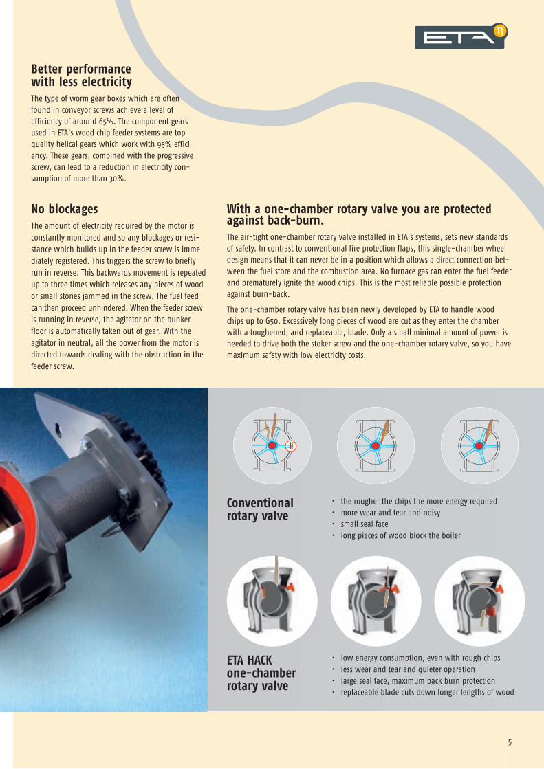
No blockagesThe amount of electricity required by the motor is constantly monitored and so any blockages or resi-stance which builds up in the feeder screw is imme-diately registered. This triggers the screw to briefly run in reverse. This backwards movement is repeated up to three times which releases any pieces of wood or small stones jammed in the screw. The fuel feed can then proceed unhindered. When the feeder screw is running in reverse, the agitator on the bunker floor is automatically taken out of gear. With the agitator in neutral, all the power from the motor is directed towards dealing with the obstruction in the feeder screw.
• low energy consumption, even with rough chips • less wear and tear and quieter operation • large seal face, maximum back burn protection • replaceable blade cuts down longer lengths of wood
• the rougher the chips the more energy required • more wear and tear and noisy • small seal face • long pieces of wood block the boiler
With a one-chamber rotary valve you are protected against back-burn.The air-tight one-chamber rotary valve installed in ETA’s systems, sets new standards of safety. In contrast to conventional fire protection flaps, this single-chamber wheel design means that it can never be in a position which allows a direct connection bet-ween the fuel store and the combustion area. No furnace gas can enter the fuel feeder and prematurely ignite the wood chips. This is the most reliable possible protection against burn-back.
The one-chamber rotary valve has been newly developed by ETA to handle wood chips up to G�0. Excessively long pieces of wood are cut as they enter the chamber with a toughened, and replaceable, blade. Only a small minimal amount of power is needed to drive both the stoker screw and the one-chamber rotary valve, so you have maximum safety with low electricity costs.
Better performance with less electricityThe type of worm gear boxes which are often found in conveyor screws achieve a level of efficiency of around 6�%. The component gears used in ETA’s wood chip feeder systems are top quality helical gears which work with 9�% effici-ency. These gears, combined with the progressive screw, can lead to a reduction in electricity con-sumption of more than �0%.
ETA HACK one-chamber rotary valve
Conventional rotary valve

6 �
Limited heat loss between firingsThe fire can be regulated between minimum and maximum settings. To satisfy moderate heating needs during autumn and spring, the heat out-put is controlled by interrupting the burning process. Because incomplete combustion would lead to a build-up of soot in the boiler and flue, the fuel is therefore allowed to burn fully down before the interval. After burning off, the primary and secondary air-flaps are closed, and there is no air flow through the boiler and so no waste heat passes up the chimney.
Automatic ash-disposal systemA boiler always works most efficiently when it is clean – and stays clean – throughout the heating season. And so, any automatic wood-burning heating system must provide for automatic ash removal throughout the system: from the grate to the heat- exchanger.
Turbulators keep the heat-exchangers tubes clear and the fire grate is regularly tilted. Two conveyor screws, driven by a single motor, carry the ash from the collection bin under the grate and also the fly ash from the heat exchangers, to the main ash bin. This can then simply be removed from the front of the boiler.
There are no narrow sections in the ash channels so they cannot be blocked by stones or nails.
Hot furnace with tilting grate Within a refractory-lined furnace, the wood flame is mixed with the turbulent secondary air, which guaran-tees that the fire burns cleanly with a high combustion temperature even when fed wood chips with up to a �0% moisture content.
Without having to pass through any corners or narrow points the chips are pushed on to the grate sideways. At pre-determined intervals, depending on the heat output level at which the boiler is set, and when combustion is complete, the grate is tilted to 90° in
order to remove ash and any foreign bodies.

6 �
Limited heat loss between firingsThe fire can be regulated between minimum and maximum settings. To satisfy moderate heating needs during autumn and spring, the heat out-put is controlled by interrupting the burning process. Because incomplete combustion would lead to a build-up of soot in the boiler and flue, the fuel is therefore allowed to burn fully down before the interval. After burning off, the primary and secondary air-flaps are closed, and there is no air flow through the boiler and so no waste heat passes up the chimney.
Optimum ignition cycle After stopping the furnace for just a short while, the refractory-lined chamber still remains hot enough for any new fuel which is fed in to be spontaneously ignited by remaining embers.It is only necessary to start the ignition fan if the fire has been out for a longer period of time. However, feedback from the lambda sensor and the exhaust temperature ensures that the fans are switched off, in order to save electricity, as soon as the fire has caught hold.
Induced draughtThe tried-and-tested induced draught technique (i.e. without a combustion air fan) commonly used when burning wood logs and pellets is also applied by ETA to burning wood chips. A quiet expulsion fan at the exit point of the boiler keeps the pressure in the boiler low, thus ensuring high operational safety and no risk of flash-back. The air-tight one-chamber rotary valve means that a usual combustion air fan is not necessary. The air required is drawn in through the regulated primary and secondary air flaps as a result of the low pressure within the boiler.
Of course, a system with an induced draught fan and no ignition fan operates with less electricity - the ETA HACK needs only �6 watts. And this already low consumption is improved even further because of the speed regulator.
Fits all chimney structuresThe wood chip heating systems from ETA can be adapted to all types of chimneys.
The induced draught fan fits into small diameter chimneys. The speed regulator controlling the draught, and the continuously regulated flaps controlling the input of the combustion air mean that no draught limiters are needed in the chimney. By setting the exhaust temperature, condensation is avoided in the brick-lined chimney and, modern stack design, this exploits the benefits of the low temperature serviceability.
Air-tight one-chamber rotary valve
Secondary air flap
Primary air flap
Vacuum
Induced
draught
fan
Chim
ney

1
2
56
7
10
7
3
4
� 9
One-chamber rotary valveEnsures protection against burn-back, large chamber – unblockable, replaceable blade and counter-blade, slow turning speed – high torque.
Induced draught fanControlled speed, quiet and economical only �6 watts, air flow not dependent on chimney draught, no pressure build-up in combustion chamber – no risk of flash-back
Heat exchanger cleaningFully automatic turbulators. When the heat exchangers are kept clean, the boiler works with maximum efficiency.
9
1112
8
� 9
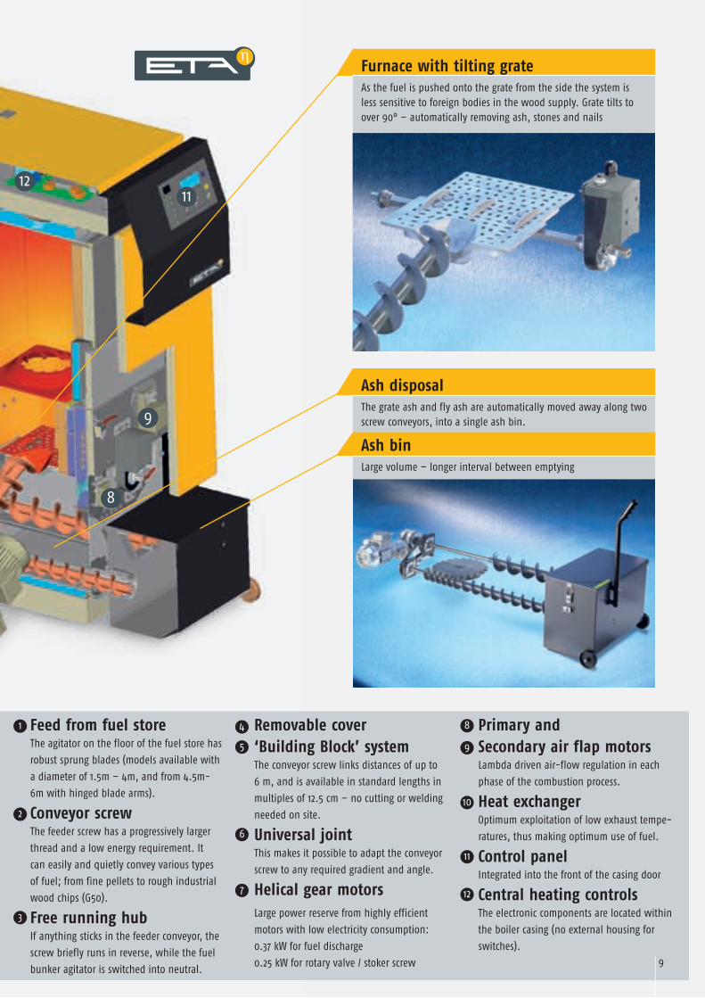
Feed from fuel store The agitator on the floor of the fuel store has
robust sprung blades (models available with
a diameter of 1.�m – �m, and from �.�m-
6m with hinged blade arms).
Conveyor screw The feeder screw has a progressively larger
thread and a low energy requirement. It
can easily and quietly convey various types
of fuel; from fine pellets to rough industrial
wood chips (G�0).
Free running hub If anything sticks in the feeder conveyor, the
screw briefly runs in reverse, while the fuel
bunker agitator is switched into neutral.
Removable cover‘Building Block’ system The conveyor screw links distances of up to
6 m, and is available in standard lengths in
multiples of 1�.� cm – no cutting or welding
needed on site.
Universal joint This makes it possible to adapt the conveyor
screw to any required gradient and angle.
Helical gear motorsLarge power reserve from highly efficient
motors with low electricity consumption:
0.�� kW for fuel discharge
0.�� kW for rotary valve / stoker screw
Primary and Secondary air flap motors Lambda driven air-flow regulation in each
phase of the combustion process.
Heat exchanger Optimum exploitation of low exhaust tempe-
ratures, thus making optimum use of fuel.
Control panel Integrated into the front of the casing door
Central heating controls The electronic components are located within
the boiler casing (no external housing for
switches).
Furnace with tilting grateAs the fuel is pushed onto the grate from the side the system is less sensitive to foreign bodies in the wood supply. Grate tilts to over 90° – automatically removing ash, stones and nails
Ash disposalThe grate ash and fly ash are automatically moved away along two screw conveyors, into a single ash bin.
Ash binLarge volume – longer interval between emptying
1
2
3
6
7
10
11
12
4 8
95
EIN
Ändern Kessel
Entaschen
Info
Zurück
Ab
Auf
Ja
i
Ä
Z JI
STEUERUNGEN
BEDIENEINHEIT
TEMPERATURANZEIGE
KESSEL Heizt
10 11
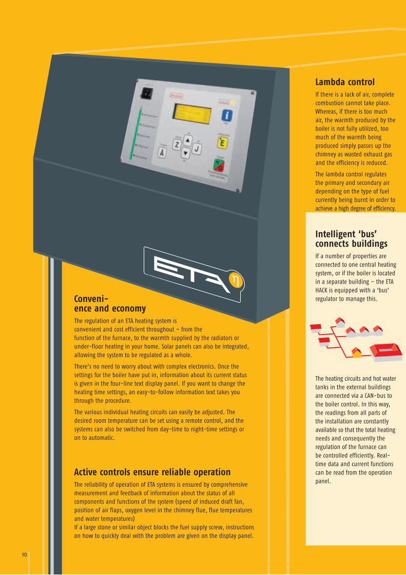
Conveni-ence and economyThe regulation of an ETA heating system is convenient and cost efficient throughout – from the function of the furnace, to the warmth supplied by the radiators or under-floor heating in your home. Solar panels can also be integrated, allowing the system to be regulated as a whole.
There’s no need to worry about with complex electronics. Once the settings for the boiler have put in, information about its current status is given in the four-line text display panel. If you want to change the heating time settings, an easy-to-follow information text takes you through the procedure.
The various individual heating circuits can easily be adjusted. The desired room temperature can be set using a remote control, and the systems can also be switched from day-time to night-time settings or on to automatic.
Active controls ensure reliable operationThe reliability of operation of ETA systems is ensured by comprehensive measurement and feedback of information about the status of all components and functions of the system (speed of induced draft fan, position of air flaps, oxygen level in the chimney flue, flue temperatures and water temperatures) If a large stone or similar object blocks the fuel supply screw, instructions on how to quickly deal with the problem are given on the display panel.
Intelligent ‘bus’ connects buildings If a number of properties are connected to one central heating system, or if the boiler is located in a separate building – the ETA HACK is equipped with a ‘bus’ regulator to manage this.
The heating circuits and hot water tanks in the external buildings are connected via a CAN-bus to the boiler control. In this way, the readings from all parts of the installation are constantly available so that the total heating needs and consequently the regulation of the furnace can be controlled efficiently. Real-time data and current functions can be read from the operation panel.
Lambda controlIf there is a lack of air, complete combustion cannot take place. Whereas, if there is too much air, the warmth produced by the boiler is not fully utilized, too much of the warmth being produced simply passes up the chimney as wasted exhaust gas and the efficiency is reduced.
The lambda control regulates the primary and secondary air depending on the type of fuel currently being burnt in order to achieve a high degree of efficiency.

EIN
Ändern Kessel
Entaschen
Info
Zurück
Ab
Auf
Ja
i
Ä
Z JI
STEUERUNGEN
BEDIENEINHEIT
TEMPERATURANZEIGE
KESSEL Heizt
10 11
Circuits de chauffage
Outside tempera-ture sensor
Room sensor + remote control
Heating circuits
Electrical power sup-ply �x�00 V, 1� A
Retu
rn te
mpe
ratu
re
Circ
ulat
ion
pum
p
Cold water
Hot water tankWood chip boilerfeeder
Complete control built-in from the start Four line easy-to-read display
Modulated output control
Lambda regulator recognises the energy content of the fuel
Computer interface
Return temperature rise control – either using a mixing valve or pump (speed-controlled).
One Heating circuit control using mixing valves (controlled by outside temperature with daily and weekly programs, and in addition room sensors and remote control for day/night/ auto-matic and pre-set temperatures +/-�°C)
Hot water control with timer
Circulation pump for hot water with timer
Combined with additional sensors, the basic equipment can also include a second heating system with mixer valves, a hot water control with two sensors, and an accumulator tank.
Extensions for your whole heating system By means of a CAN-Bus the control system can be expanded to cover a number of heating circuits with addi tional components – mixer valves, boi lers and other special elements.
Accumulator tank management An accumulator tank is not normally necessary in a standard system. However, one is recommended where the heating requirement is low in summer, or during the change of seasons, or where there is a connection to a large solar heating installation.
Hot water tank regulated with two sensors (top START, bottom STOP). In connection with a large boiler, this reduced the number of furnace start-ups in summer.
External hot water heat exchanger for large hot water requirements (protection against legionnaires’ disease).
Solar energy for hot water tank and accumulator
Oil/gas-back up for times of peak use
Transport pump for small networks
Outside temperature sensor
Room sensor + remote control
Control extensionAdditional operation panel
Oil/gas boiler Accumulator tank Hot water tank Solar instal-lation
Austragung Wood chip boiler
Rück
lauf
-An
hebu
ng
Circ
ulat
ion
pum
p
Electrical power supply �x�00 V, 1�A CA
N-Bu
s (m
ax. �
00m
)
1� 1�
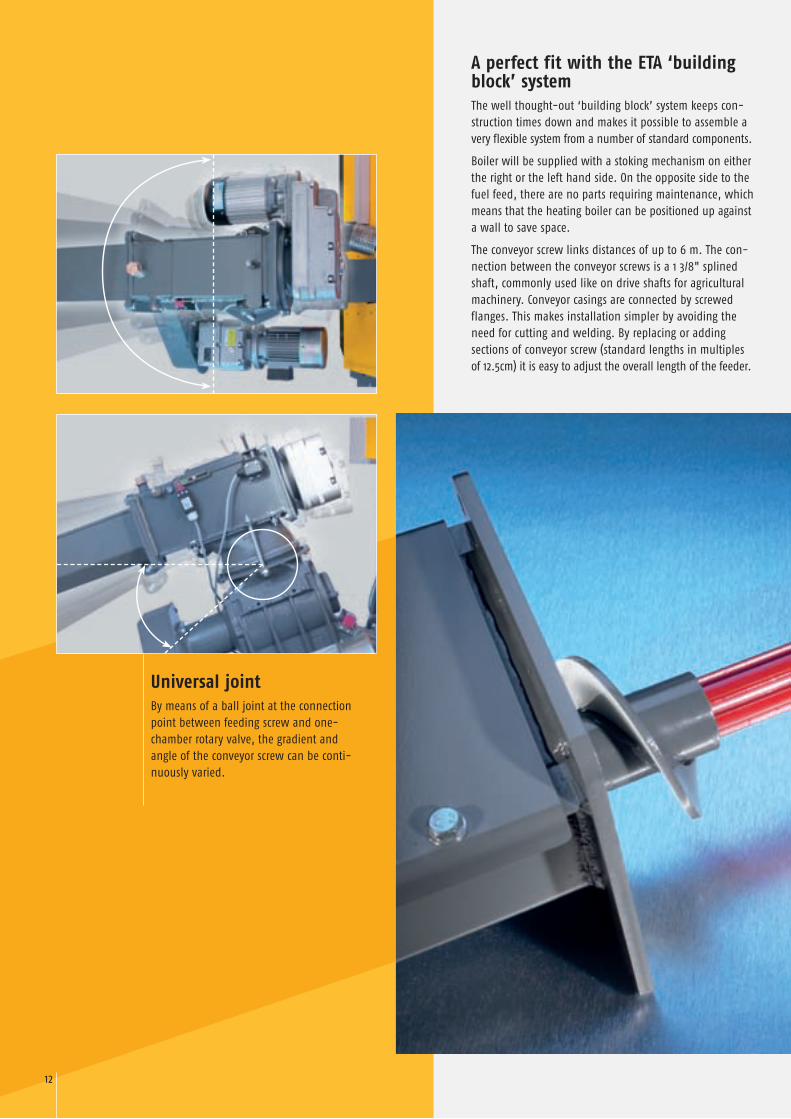
Universal jointBy means of a ball joint at the connection point between feeding screw and one-chamber rotary valve, the gradient and angle of the conveyor screw can be conti-nuously varied.
A perfect fit with the ETA ‘building block’ systemThe well thought-out ‘building block’ system keeps con-struction times down and makes it possible to assemble a very flexible system from a number of standard components.
Boiler will be supplied with a stoking mechanism on either the right or the left hand side. On the opposite side to the fuel feed, there are no parts requiring maintenance, which means that the heating boiler can be positioned up against a wall to save space.
The conveyor screw links distances of up to 6 m. The con-nection between the conveyor screws is a 1 �/�" splined shaft, commonly used like on drive shafts for agricultural machinery. Conveyor casings are connected by screwed flanges. This makes installation simpler by avoiding the need for cutting and welding. By replacing or adding sections of conveyor screw (standard lengths in multiples of 1�.�cm) it is easy to adjust the overall length of the feeder.
1� 1�
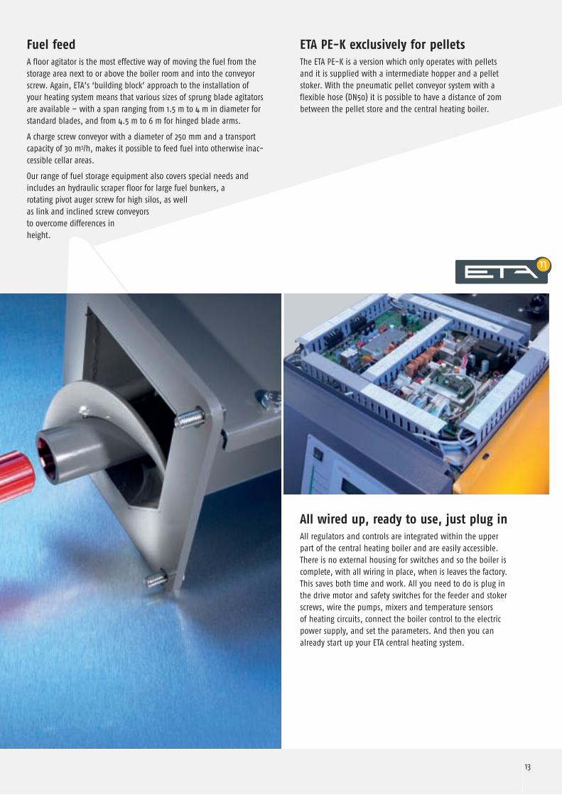
Fuel feedA floor agitator is the most effective way of moving the fuel from the storage area next to or above the boiler room and into the conveyor screw. Again, ETA’s ‘building block’ approach to the installation of your heating system means that various sizes of sprung blade agitators are available – with a span ranging from 1.� m to � m in diameter for standard blades, and from �.� m to 6 m for hinged blade arms.
A charge screw conveyor with a diameter of ��0 mm and a transport capacity of �0 m�/h, makes it possible to feed fuel into otherwise inac-cessible cellar areas.
Our range of fuel storage equipment also covers special needs and includes an hydraulic scraper floor for large fuel bunkers, a rotating pivot auger screw for high silos, as well as link and inclined screw conveyors to overcome differences in height.
ETA PE-K exclusively for pelletsThe ETA PE-K is a version which only operates with pellets and it is supplied with a intermediate hopper and a pellet stoker. With the pneumatic pellet conveyor system with a flexible hose (DN�0) it is possible to have a distance of �0m between the pellet store and the central heating boiler.
All wired up, ready to use, just plug inAll regulators and controls are integrated within the upper part of the central heating boiler and are easily accessible. There is no external housing for switches and so the boiler is complete, with all wiring in place, when is leaves the factory. This saves both time and work. All you need to do is plug in the drive motor and safety switches for the feeder and stoker screws, wire the pumps, mixers and temperature sensors of heating circuits, connect the boiler control to the electric power supply, and set the parameters. And then you can already start up your ETA central heating system.
1� 1�
Neue Formen der Kommunika-tionstechnologie tauchen nicht mehr behutsam am fernen Hori-zont der Zukunft auf. Sie bilden bereits einen Teil unserer Welt, bevor die Konsequenzen für unsere Formen der Vermittlung und Wahrnehmung abschätzbar geworden sind.
9�10�
10�
�0% �0% �0%
1161�1
1��
�0% �0% �0%
�0 ���6
�0% �0% �0%
96100
10�
�0% �0% �0%
�6 �961
�0% �0% �0%
6��0 ��
�0% �0% �0%
1�0
�0
60
�0
100
1�0
�0
0
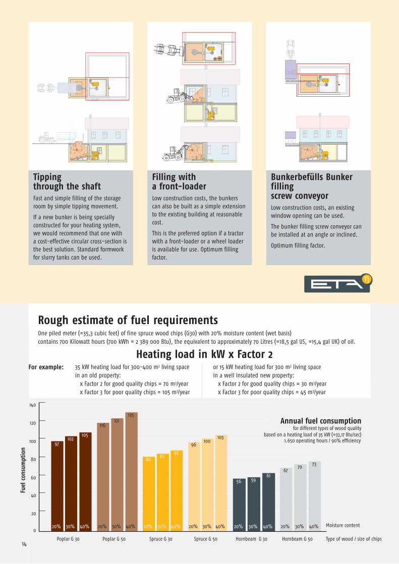
Tipping through the shaft Fast and simple filling of the storage room by simple tipping movement.
If a new bunker is being specially constructed for your heating system, we would recommend that one with a cost-effective circular cross-section is the best solution. Standard formwork for slurry tanks can be used.
Filling with a front-loaderLow construction costs, the bunkers can also be built as a simple extension to the existing building at reasonable cost.
This is the preferred option if a tractor with a front-loader or a wheel loader is available for use. Optimum filling factor.
Bunkerbefülls Bunker filling screw conveyorLow construction costs, an existing window opening can be used.
The bunker filling screw conveyor can be installed at an angle or inclined.
Optimum filling factor.
Rough estimate of fuel requirementsOne piled meter (=��,� cubic feet) of fine spruce wood chips (G�0) with �0% moisture content (wet basis) contains �00 Kilowatt hours (�00 kWh = � ��9 000 Btu), the equivalent to approximately �0 Litres (=1�,� gal US, =1�,� gal UK) of oil.
Heating load in kW x Factor 2
Annual fuel consumptionfor different types of wood quality
based on a heating load of �� kW (=��,1� Btu/sec)
Fuel
con
sum
ptio
n
Poplar G �0 Poplar G �0 Spruce G �0 Spruce G �0 Hornbeam G �0 Hornbeam G �0
Moisture content
Type of wood / size of chips
�� kW heating load for �00-�00 m� living space in an old property: x Factor � for good quality chips = �0 m�/year x Factor � for poor quality chips = 10� m�/year
or 1� kW heating load for �00 m� living space in a well insulated new property: x Factor � for good quality chips = �0 m�/year x Factor � for poor quality chips = �� m�/year
1.6�0 operating hours / 90% efficiency
For example:

14 15
ETA HACK 20 25 35 50 70 90 130
Rated capacity (Wood Chips W25-S160) kW 5,9-19,9 7,7-26,0 10,5-35,0 13,6-49,5 21,0-70,0 26,0-88,0 38,0-133,0
Efficiency partial/full load – spruce chips * % 92,8 / 92,7 92,9 / 92,2 92,9 / 91,7 92,8 / 90,8 92,3 / 90,9 91,8 / 91,0 94,9 / 92,0
Efficiency partial/full load – pellets * % 90,6 / 93,8 93,6 / 92,1 92,1 / 92,7 91,8 / 92,3 91,4 / 91,8 93,6 / 92,1
Transport dimensions W x D x H mm 710 x 1.100 x 1.495 810 x 1.249 x 1.696930 x 1.520
x 1.770
Width without insulation mm 590 690 790
Weight with / without rotary valve and stoker kg 735 / 590 735 / 590 736 / 591 737 / 592 1.009 / 864 1.011 / 866 1.320 / 1.175
Water content Liter 117 196 290
Water flow resistance (ΔT=20°)Pa / mWS
90 / 0,009 160 / 0,016 280 / 0,028 550 / 0,055 970 / 0,097 1.600 / 0,16 750 / 0,075
Ash bin capacity Liter 35 44 110
Exhaust mass flow rate partial/full load g/s 5,7 / 15,2 7,4 / 19,2 9,6 / 25,0 12,4 / 32,2 19,3 / 45,5 21,8 / 55,3 28,3 / 85,3
CO2-content in dry exhaust gas partial/full load % 8,5 / 11,0 8,5 / 11,5 9,0 / 12,0 9,0 / 13,5 9,0 / 13,5 10,0 / 14,0 11,0 / 13,5
Exhaust temperature partial/full load * °C 70 / 110 75 / 130 80 / 140 85 / 150 85 / 145 90 / 155 76 / 145
Chimney draught minimum-maximum2 Pa partial load / 5 Pa full load
up to 15 Pa no draught limiter required
Emissions carbon monoxide (CO) mg/MJ 17 to 108 7 to 62 10 to 48 16 to 31 13 to 19 5 to 13 9 to 38
mg/m³ 13%O2
24 to 156 10 to 91 15 to 72 24 to 46 20 to 28 8 to 19 14 to 55
Electrical power consumption
spruce wood chips partial/full load *W 73 / 129 91 / 147 104 / 175 120 / 215 144 / 252 166 / 310 178 / 458
Electrical power consumption
pellets partial/full load *W 67 / 98 70 / 112 74 / 124 100 / 132 106 / 140 107 / 253
Maximum permitted operating pressure 3 barRange of setting for flow temperature 70 – 85°CMaximum permitted operating temperature 95°CMinimum return temperature 60°C
Boiler classification 3 according to EN 303-5Suitable fuel Wood Chips G30/G50 up to W35, ÖNORM M 7133, Pellets ÖNORM M 7135, DIN 51731Power supply 3 x 400V / 50Hz / 13A
Technical Data
Measurements in ( ) for 70 and 90 kW
in [ ] for 130 kW
BLT Wieselburg Austria
TÜV Southern Germany
Holzenergie Switzerland
Institute for fire protection
In accordance with EU regulations
Proven quality
* Results taken from test report by the BLT Wieselburg, Protocol number 047/03, 048/03, 049/03, 005/04, 026/07, 027/07 .Reports of the Testing Centre at BLT Wieselburg are available via Internet: blt.josephinum.at ( > Prüfberichte > Hackgutfeuerungen)
Boiler will be supplied with stoker on either the right of the left hand side.
Gradient and angle with globe joint continuously adjustable
VL..Flow RL..Return EW..Drain ST..Safety heat exchanger
R5/4“ (R6/4“) female R5/4“ (R6/4“) female R1/2“ female R1/2“ male
Exha
ust w
ith fl
ue g
as re
circu
latio
n 62
mm
hig
her
www.eta.co.at
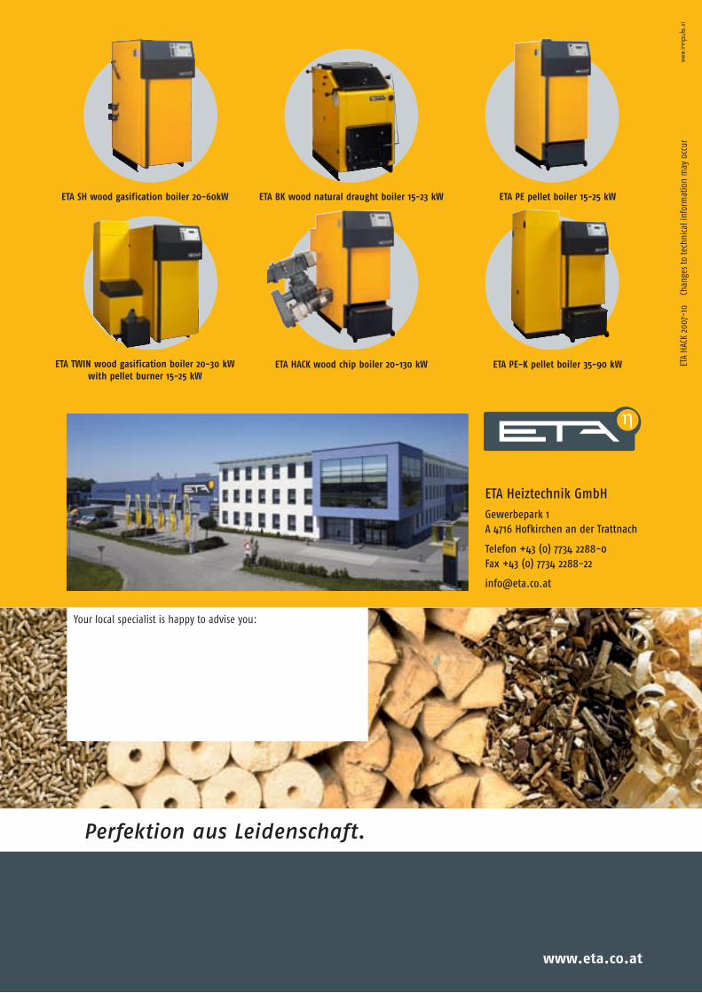
ETA SH wood gasification boiler 20-60kW ETA BK wood natural draught boiler 15-23 kW ETA PE pellet boiler 15-25 kW
ETA Heiztechnik GmbHGewerbepark 1 A 4716 Hofkirchen an der Trattnach
Telefon +43 (0) 7734 2288-0 Fax +43 (0) 7734 2288-22
Your local specialist is happy to advise you:
ETA
HACK
�00
�-10
C
hang
es to
tech
nica
l inf
orm
atio
n m
ay o
ccur
ETA TWIN wood gasification boiler 20-30 kWwith pellet burner 15-25 kW
ETA HACK wood chip boiler 20-130 kW ETA PE-K pellet boiler 35-90 kW
Perfektion aus Leidenschaft.