Embed Size (px)
Citation preview

User Manual---Apply to WL-R100 Series Industrial 3G/4G Router
V1.0http://www.wlink-tech.com
April, 2016
WL-R100 Series Router User Manual
www.wlink-tech.com 1
Copyright © ShenzhenWLINK Technology Company Limited 2012 ~ 2016Without our written approval, Anyone can’t extract, copy whole or part of content of this file andcan’t spread out in any format.
CautionDue to product updates or functional upgrading, we may renew the content of this file, and thisfile only for reference. All statement, information, suggestion.etc in this file does not composeany form of guarantee and we WLINK reserves the right of final explanation.
Shenzhen WLINK Technology Company Limited
Add: 3F, Yiben Building, Chaguang Road, Xili, Nanshan Dist., China, 518000
Web: http://www.wlink-tech.com
Service Email: [email protected]
Tel: 86-755-86089513
Fax: 86-755-26059261

WL-R100 Series Router User Manual
www.wlink-tech.com 2
Contents
1 Product Introduction......................................................................................................................4
1.1 Product overview................................................................................................................4
1.2 Model introduction..............................................................................................................4
1.3 Product Appearance..........................................................................................................5
1.4 Typical Application Diagram.............................................................................................5
1.5 Features...............................................................................................................................6
2 Hardware Installation....................................................................................................................7
2.1 Panel.................................................................................................................................... 7
2.2 LED Status..........................................................................................................................8
2.3 Dimension............................................................................................................................9
2.4 How to Install...................................................................................................................... 9
3 Router Configuration...................................................................................................................11
3.1 Local Configure................................................................................................................ 11
3.2 Basic Configuration..........................................................................................................12
3.3 Advanced Network Setting.............................................................................................17
3.4 Firewall...............................................................................................................................25
3.5 VPN Tunnel.......................................................................................................................26
3.6 Administration...................................................................................................................32
3.7 Debugging Setting........................................................................................................... 40
WL-R100 Series Router User Manual
www.wlink-tech.com 3
3.8 “RST” Button for Restore Factory Setting....................................................................43
3.9 Appendix (For advanced optional features only)........................................................44
WL-R100 Series Router User Manual
www.wlink-tech.com 4
1 Product Introduction
1.1 Product overviewWLINK industrial Router is based on industrial grade design, built-in high-powered 32bitMIPS processor, and multi-band 4G/3G communication module, support WCDMA,HSPA+,4G FDD/TDD etc., provide quick and convenient internet access or private networktransmission to customer, provide wire-line network or wireless WLAN share high speedaccess, meanwhile, customized high security VPN (Open VPN、IPSec、SSL), to constructsafe channel, widely used in financial, electric power, environment, oil, transportation,security, etc..WLINK industrial series router provide GUI, optional CLI configuration interface, customercan configure by IE explore or Telnet/SSH, various configuration method, concise andfriendly interface make configuring and managing of all router terminal easier ,meanwhile,WLINK provide M2M terminal management platform to manage all router terminal withremote management. User can monitor all terminals which connected to platformsuccessfully by this platform, provide long-distance control, parameter configuration, andlong-distance upgrade service.
1.2 Model introductionWLINK industrial grade router series have single module / single SIM card, single module/ double SIM card, double module / double SIM card design, support multi-band frequencyWCDMA, HSPA+, 4G FDD/TDD etc., and downward compatibility to GPRS、EDGE、
CDMA 1x, etc., optional GPS module Expansion positioning function, to suit differentrequirement and different network environment of different operators. Our Router serieshave many model for option, below is the product model indications in detail, for moreoptional models, please consult local distributors /resellers.

WL-R100 Series Router User Manual
www.wlink-tech.com 5
1.3 Product Appearance
Table 1-1 WLINKRouter Appearance
Series R100 R200 R210 R520
Appearance
Ports1*LAN
1*RS232
2*LAN/ 1*LAN+ 1*WAN
GPS or WLAN(11n1T1R)
2*LAN(Default) +DualSIM
GPS, WLAN Optional
1*WAN + 4*LAN +
single module/dual SIM,dual module/dual SIM
Product
categorySingle port router Dual-port Wi-Fi router Multi-port Wi-Fi router Multi-functional Wi-Fi
router
1.4 Typical Application DiagramWLINK 4G/3G Router widely used in Telecom, economic, advertisement, traffic, environmentprotection business area.
For example, in economic area, R100 Series Router connect server by IPSec & GRE toensure data security, tiny design makes it could installed into ATM machine.All thesetechnology ensured safe and reliable data transmission, and minimize the probability ofnetwork disconnection, and maximize the usability of economic business like ATM, POS .etc.

WL-R100 Series Router User Manual
www.wlink-tech.com 6
Figure 1-1 Network Topology
WLINK industrial router is based on mobile wireless public network or private network,build wireless data channel in mature network, to lower down the cost of wireless datatransmission and technique.
1.5 Features Various cellular module optional, LTE/HSPA+/EVDO/CDMA2000 optional
Support virtual data and private network(APN/VPDN)
Optional support RS-232/RS-485 interface data transparent transmission andprotocol conversion
Support on-demand dialing, include timing on/off-line, voice or SMS controlon/off-line, data trigger online or link idle offline
Support TCP/IP protocol stack, support Telnet, HTTP, SNMP, PPP, PPPoE, etc.,network protocol
Support VPN Client(PPTP, L2TP),optional support Open VPN, IPSec, HTTPs,SSH, etc. advanced VPN function
Provide friendly user interface, use normal web internet explorer to easilyconfigure and manage, long-distance configure Telnet/SSH.
Optional IPv6 protocol stack
Optional support M2M terminal management platform
WDT watchdog design, keep system stable
Customization as customer’s demand

WL-R100 Series Router User Manual
www.wlink-tech.com 7
2 Hardware Installation
This chapter is mainly for installation introduction, there would be some differencebetween the scheme and real object. But the difference doesn’t have any influence toproducts performance.
2.1 Panel
Table 1-1 WL-R100 -Structure
WLINK Tech WL-R100 series
Front
Rear
There are some different for Antenna interface and indicator light for theexpanded GPS series.
Table 2-1 Router Interface
Port Instruction Remark
USIM Plug type SIM Slot, support 1.8/3V/5V automaticdetection
Main 4G/3G antenna, SMA connector, 50Ω

WL-R100 Series Router User Manual
www.wlink-tech.com 8
Port Instruction Remark
Aux/GPS 4G Aux Antenna or GPS Antenna, SMA connector,50Ω
Optional
LAN 10/100Base-TX,MDI/MDIX self-adaption,
RST Reset button,(press on button 5 seconds)
PWR Power connector 7.5 ~32V DC
COM Three pins serial port, suitable for collection devicewith RS-232 or RS-485 interface, for wireless datatransmission.
2.2 LED Statussilk-screen color status Indication
NET
Green Strong Signal
Orange Normal Signal
Red Weak Signal
Solid light Connected 4G successfully
Blinkingquickly(0.5s)
Dialing
LAN
Green Solid light Connected
Green Blinking Data Sending
Green Dark Not connected
PWR Green Solid light Router OS is running.
Table 2-2 Router LED indictor Status
WL-R100 Series Router User Manual
www.wlink-tech.com 9
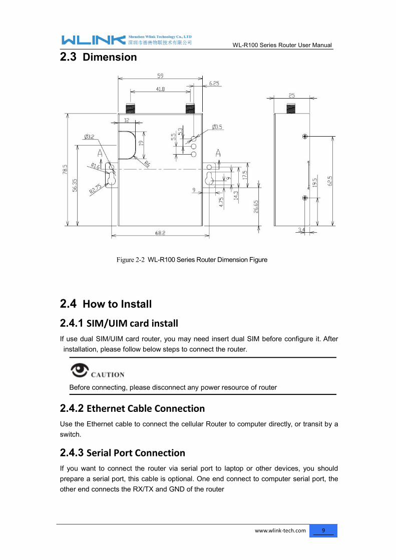
2.3 Dimension
Figure 2-2 WL-R100 Series Router Dimension Figure
2.4 How to Install2.4.1 SIM/UIM card installIf use dual SIM/UIM card router, you may need insert dual SIM before configure it. Afterinstallation, please follow below steps to connect the router.
Before connecting, please disconnect any power resource of router
2.4.2 Ethernet Cable ConnectionUse the Ethernet cable to connect the cellular Router to computer directly, or transit by aswitch.
2.4.3 Serial Port ConnectionIf you want to connect the router via serial port to laptop or other devices, you shouldprepare a serial port, this cable is optional. One end connect to computer serial port, theother end connects the RX/TX and GND of the router

WL-R100 Series Router User Manual
www.wlink-tech.com 10
Before connecting, please disconnect any power resource of router
2.4.4 Power SupplyIn order to get high reliability, WLINK Series Router adapt supports wide voltage inputrange: +7.5V~+32VDC, support hot plug and complex application environment.
2.4.5 ReviewAfter insert the SIM/UIM card, connect Ethernet cable and necessary antenna, connectpower cable.
Please connect the antenna before connect the power cable, otherwise the signalmaybe poor because of impedance mismatching.
Notice:
Step 1 Check antenna connection.
Step 2 Check SIM/UIM card, confirm SIM/UIM card is available.
Step 3 Power on the industrial Router
----END

WL-R100 Series Router User Manual
www.wlink-tech.com 11
3 Router Configuration
This Chapter introduces the parameter configuration of the router, the router can beconfigured via IE, Firefox, or chrome.
3.1 Local ConfigureThe router supports to be configured by local Ethernet port, you could specify a static IP orDHCP get IP for your computer. The default IP address is 192.168.1.1,subnet mask is255.255.255.0, please refer to followings:
Step 1 Click “start > control panel”, find “Network Connections” icon and double click it toenter, select “Local Area Connection” corresponding to the network card on thispage. Refer to the figure below.
Figure 3-3 Network Connection
Step 2 Obtain a IP address automatically or set up IP address,192.168.1.xxx(XXX can beany number between 2~254)
Step 3 Run an Internet Explorer and visit “http://192.168.1.1/”, to enter identify page.
User should use the default user name and password when log in for the first time

WL-R100 Series Router User Manual
www.wlink-tech.com 12
Figure 3-4 User Identify Interface
----END
3.2 Basic Configuration
Different software version have different web configuration interface, below take WL-R100as example.After access the WEB interface, you can check the current status of Router, or modifyrouter configuration via web interface, below is the introduction for the common setting.

WL-R100 Series Router User Manual
www.wlink-tech.com 13
Figure 3-5 Router Status GUI
3.2.1 Cellular Network ConfigureStep 1 Single Click Basic Network-> Cellular, you can modify relevant parameter
according to the application.
Figure 3-1 Cellular Settings GUI
Table 3-1 Cellular Setting Parameter Instruction
Parameter Instruction
ICMP check To enable or disable ICMP check rules. Enable the ICMP checkand setup a reachable IP address as destination IP. OnceICMP check failed, router will reconnect/reboot system asoptional..
Cellular Traffic Check There is Rx/Tx as options. Once no Rx/Tx data, router willrouter will reconnect/reboot system as options.
Connect Mode Keep alive (Auto-online).The router will automaticallyconnect 3G/4G network and keep online.
Connect On Demand. Idle offline if no data from LAN to3G/4G within defined time.

WL-R100 Series Router User Manual
www.wlink-tech.com 14
Parameter Instruction Schedule, Define online and offline time. This function
need to enable NTP function, Call/SMS Triggered. Call/SMS trigger router online. Manually. Connect 3G/4G network by manual.
CIMI Send Send CIMI to defined IP and port by TCP protocol.
SMS Code SMS identifying code. Router just identifies the unique code toimplement SMS command.
PIN Code Unlock the SIM PIN code.
Operator Lock Lock operators via MCC/MNC
Service Code The default service code as *99#.
APN APN, provided by local ISP, usually CDMA/EVDO network donot need this parameter.
User SIM card user name is provided by ISP
Password SIM card password is provided by ISP
Auth Type Support PAP/Chap/MS-Chap/MS-Chapv2
Local IP Add Defined SIM IP from operator.
【ICMP Check】
Enable ICMP, Router will automatically check whether the defined IP address isreachable per 60s. If the IP address is unreachable and ICMP check is timeout atthe first time, it will check 2 times every 3 seconds. If the third time is still failed, therouter will redial.
The ICMP Check IP is a public IP or company server IP address.
【Cellular Traffic Check】
【Check Mode】there are Rx(Receive), Tx(Transmission) and Rx/Tx check modes.
【Rx】Router will check the 3G/LTE cellular receiver traffic. If no receiver traffic withinthe defined check interval, the router will implement the specified action reconnect

WL-R100 Series Router User Manual
www.wlink-tech.com 15
or reboot.
Step 2 After Setting, please click “save” icon.
----End
3.2.2 LAN SettingStep 1 Single Click “ Basic Network>LAN” to enter below interface
Figure 3-2 LAN Setting GUI
Table 3-2 LAN Setting Instruction
Parameter Instruction
Router IP Address Router IP address, default IP is 192.168.1.1
Subnet Mask Router subnet mask, default mask is 255.255.255.0
DHCP Dynamic allocation IP service, after enable, it will show theIP address range and options of lease
IP Address Range IP address range within LAN
Lease The valid time
Step 2 After setting, please click “save” to finish, the device will reboot.
----End
WL-R100 Series Router User Manual
www.wlink-tech.com 16
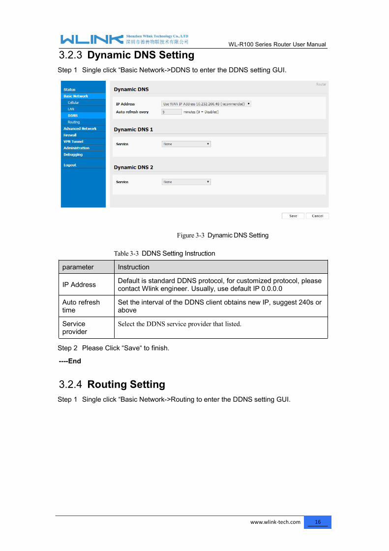
3.2.3 Dynamic DNS SettingStep 1 Single click “Basic Network->DDNS to enter the DDNS setting GUI.
Figure 3-3 Dynamic DNS Setting
Table 3-3 DDNS Setting Instruction
parameter Instruction
IP Address Default is standard DDNS protocol, for customized protocol, pleasecontact Wlink engineer. Usually, use default IP 0.0.0.0
Auto refreshtime
Set the interval of the DDNS client obtains new IP, suggest 240s orabove
Serviceprovider
Select the DDNS service provider that listed.
Step 2 Please Click “Save“ to finish.
----End
3.2.4 Routing SettingStep 1 Single click “Basic Network->Routing to enter the DDNS setting GUI.

WL-R100 Series Router User Manual
www.wlink-tech.com 17
Figure 3-4 Routing Setting
Table 3-4 Routing Setting Instruction
Parameter Instruction
Destination Router can reach the destination IP address.
Gateway Next hop IP address which the router will reach
Subnet Mask Subnet mask for destination IP address
Metric Metrics are used to determine whether one particular route shouldbe chosen over another.
Interface Interface from router to gateway.
Description Describe this routing name.
Step 2 Please Click “ Save “ to finish.
3.3 Advanced Network Setting3.3.1 Port ForwardingStep 1 Please click “Advanced Network > Port Forwarding” to enter the GUI, you may
modify the router name, Host name and Domain name according to theapplication requirement.

WL-R100 Series Router User Manual
www.wlink-tech.com 18
Figure 3-5 Port Forwarding GUI
Table 3-5 “Port Forwarding” Instruction
Parameter Instruction
Protocol Support UDP, TCP, both UDP and TCP
Src. Address Source IP address. Forward only if from this address.
Ext. Ports External ports. The ports to be forwarded, as seen from theWAN.
Int. Port Internal port. The destination port inside the LAN. If blank,the destination port is the same as Ext Ports. Only one portper entry is supported when forwarding to a differentinternal port.
Int. Address Internal Address. The destination address inside the LAN.
Description Remark the rule
Step 2 Please click ”save” to finish
----End
3.3.2 Port RedirectingStep 1 Please click “Advanced Network > Port Redirecting” to enter the GUI, you may
modify the router name, Host name and Domain name according to theapplication requirement.

WL-R100 Series Router User Manual
www.wlink-tech.com 19
Figure 3-6 Port Forwarding GUI
Table 3-6 “Port Redirecting” Instruction
Parameter Instruction
Protocol Support UDP, TCP, both UDP and TCP
Int Port Internal port.
Dst. Address The redirecting IP address.
Ext. Ports External port for redirection.
Description Remark the rule
Step 2 Please click ”save” to finish
----End
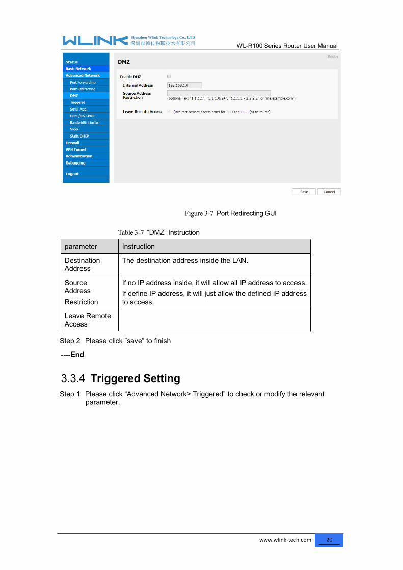
3.3.3 DMZ SettingStep 1 Please click “Advanced Network> DMZ” to check or modify the relevant
parameter.
WL-R100 Series Router User Manual
www.wlink-tech.com 20
Figure 3-7 Port Redirecting GUI
Table 3-7 “DMZ” Instruction
parameter Instruction
DestinationAddress
The destination address inside the LAN.
SourceAddressRestriction
If no IP address inside, it will allow all IP address to access.If define IP address, it will just allow the defined IP addressto access.
Leave RemoteAccess
Step 2 Please click ”save” to finish
----End
3.3.4 Triggered SettingStep 1 Please click “Advanced Network> Triggered” to check or modify the relevant
parameter.

WL-R100 Series Router User Manual
www.wlink-tech.com 21
Figure 3-8 Triggered GUI
Table 3-8 “Triggered” Instruction
parameter Instruction
Protocol Support UDP, TCP, both UDP and TCP
Triggered Ports Trigger Ports are the initial LAN to WAN "trigger".
TransferredPorts
Forwarded Ports are the WAN to LAN ports that areopened if the "trigger" is activated.
Note Port triggering opens an incoming port when yourcomputer is using a specified outgoing port for specifictraffic.
Step 2 Please click ”save” to finish.
----End
3.3.5 Serial App. SettingStep 1 Please click “Advanced Network> Serial App” to check or modify the relevant
parameter.

WL-R100 Series Router User Manual
www.wlink-tech.com 22
Figure 3-9 Serial App Setting GUI
Table 3-9 “Serial App” Instruction
Parameter Instruction
Serial to TC/IPmode
Support Disable, Server and Client mode. Such as Client.
Server IP/Port IP address and domain name are acceptable for Server IP
Socket Type Support TCP/UDP protocol
Socket Timeout Router will wait the setting time to transmit data to serialport.
Serial Timeout Serial Timeout is the waiting time for transmitting the datapackage that is less the Packet payload. If the last packageequals to the Packet payload, Serial port will transmit itimmediately. The default setting is 500ms.
Packet payload Packet payload is the maximum transmission length forserial port data packet. The default setting is 1024bytes.
Heart-beatContent
Send heart beat to the defined server to keep router online.Meantime, it’s convenient to monitor router from server.
Heart beatInterval
Heart beat interval time
Baud Rate 115200 as default
Parity Bit None as default
Data Bit 8bit as default
Stop Bit 1bit as default

WL-R100 Series Router User Manual
www.wlink-tech.com 23
Serial port connectionPINs DB9(male)
V+V-
GND ---- 5RX ---- 3TX ---- 2
Step 2 Please click ”save” to finish.
----End
3.3.6 UPnp/NAT-PMP SettingStep 1 Please click “Advanced Network> Upnp/NAT-PMP” to check or modify the
relevant parameter.
Figure 3-10 UPnp/NAT-PMP Setting GUI
Step 2 Please click ”save” to finish.
3.3.7 Bandwidth Control SettingStep 1 Please click “Advanced Network> Static DHCP” to check or modify the relevant
parameter.

WL-R100 Series Router User Manual
www.wlink-tech.com 24
Figure 3-11 Bandwidth Control Setting GUI
Step 2 Please click ”save” to finish.
3.3.8 VRRP SettingStep 1 Please click “Advanced Network> Static DHCP” to check or modify the relevant
parameter.
Figure 3-12 VRRP Setting GUI
Step 2 Please click ”save” to finish.
3.3.9 Static DHCP SettingStep 1 Please click “Advanced Network> Static DHCP” to check or modify the relevant

WL-R100 Series Router User Manual
www.wlink-tech.com 25
parameter.
Figure 3-13 Static DHCP Setting GUI
Step 2 Please click ”save” to finish.
3.4 Firewall3.4.1 IP/URL FilteringStep 1 Please click “Firewall> IP/URL Filtering” to check or modify the relevant
parameter.

WL-R100 Series Router User Manual
www.wlink-tech.com 26
Table 3-10 “IP/URL Filtering” Instruction
Parameter Instruction
IP/MAC/PortFiltering
Support IP address, MAC address and port filter.
Key WordFiltering
Support key word filter.
URL Filtering Support URL filter.
Step 2 Please click ”save” to finish.
3.4.2 Domain FilteringStep 1 Please click “Firewall> Domain Filtering” to check or modify the relevant
parameter.
Figure 3-14 Domain Filtering Setting GUI
Table 3-11 “GRE” Instruction
Parameter Instruction
Default Policy Support black list and white list
Local IPAddress
Local IP address for LAN.
Domain Support Domain filter.
Step 2 Please click ”save” to finish.
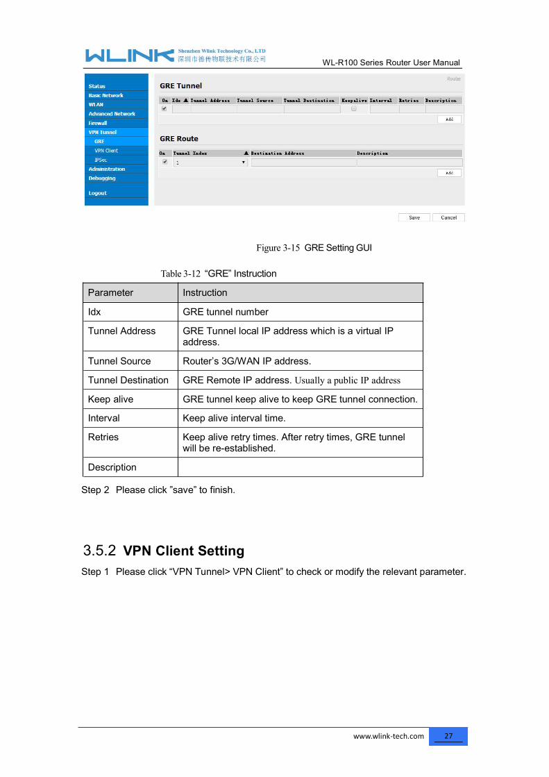
3.5 VPN Tunnel3.5.1 GRE SettingStep 1 Please click “VPN Tunnel> GRE” to check or modify the relevant parameter.
WL-R100 Series Router User Manual
www.wlink-tech.com 27
Figure 3-15 GRE Setting GUI
Table 3-12 “GRE” Instruction
Parameter Instruction
Idx GRE tunnel number
Tunnel Address GRE Tunnel local IP address which is a virtual IPaddress.
Tunnel Source Router’s 3G/WAN IP address.
Tunnel Destination GRE Remote IP address. Usually a public IP address
Keep alive GRE tunnel keep alive to keep GRE tunnel connection.
Interval Keep alive interval time.
Retries Keep alive retry times. After retry times, GRE tunnelwill be re-established.
Description
Step 2 Please click ”save” to finish.
3.5.2 VPN Client SettingStep 1 Please click “VPN Tunnel> VPN Client” to check or modify the relevant parameter.

WL-R100 Series Router User Manual
www.wlink-tech.com 28
Table 3-13 “VPN Client” Instruction
parameter Instruction
VPN Mode VPN Mode for PPTP and L2TP
Server Address VPN Server IP address.
User name As the configuration requested.
Password As the configuration requested.
Encryption As the configuration requested.
StatelessMPPE
As the configuration requested.
Accept DNS As the configuration requested.
Remote Subnet As the configuration requested.
Create NAT onTunnel
As the configuration requested.
MTU MTU is 1450bytes as default
MRU MRU is 1450bytes as default
Local IP Defined Local IP address for tunnel

WL-R100 Series Router User Manual
www.wlink-tech.com 29
parameter InstructionAddress
Step 2 Please click ”save” to finish.
3.5.3 IPSec Setting
3.5.3.1 IPSec Group SetupStep 1 Please click “IPSec> Group Setup” to check or modify the relevant parameter.
Table 3-14 “ IPSec Group Setup” Instruction
parameter Instruction
IPSecExtensions
Support Standard IPSec, GRE over IPSec, L2TP overIPSec

WL-R100 Series Router User Manual
www.wlink-tech.com 30
parameter Instruction
Local SecurityInterface
Defined the IPSec security interface
LocalSubnet/Mask
IPSec local subnet and mask.
Local Firewall Forwarding-firewalling for Local subnet
RemoteIP/Domain
IPsec peer IP address/domain name.
RemoteSubnet/Mask
IPSec remote subnet and mask.
RemoteFirewall
Forwarding-firewalling for Remote subnet
Step 2 Please click ”save” to finish.
3.5.3.2 IPSec Basic SetupStep 1 Please click “IPSec >Basic Setup ” to check or modify the relevant parameter.
Table 3-15 “ IPSec Basic Setup” Instruction
parameter Instruction
Keying Mode IKE preshared key
Phase 1 DHGroup
Select Group1, Group2, Group5 from list. It must bematched to remote IPSec setting.
Phase 1Encryption
Support 3DES, AES-128, AES-192, AES-256
WL-R100 Series Router User Manual
www.wlink-tech.com 31
parameter Instruction
Phase 1Authentication
Support HASH MD5 and SHA
Phase 1 SALife Time
IPSec Phase 1 SA lifetime
Phase 2 DHGroup
Select Group1, Group2, Group5 from list. It must bematched to remote IPSec setting.
Phase 2Encryption
Support 3DES, AES-128, AES-192, AES-256
Phase 2Authentication
Support HASH MD5 and SHA
Phase 2 SALife Time
IPSec Phase 2 SA lifetime
Preshared Key Preshared Key
Step 2 Please click ”save” to finish.
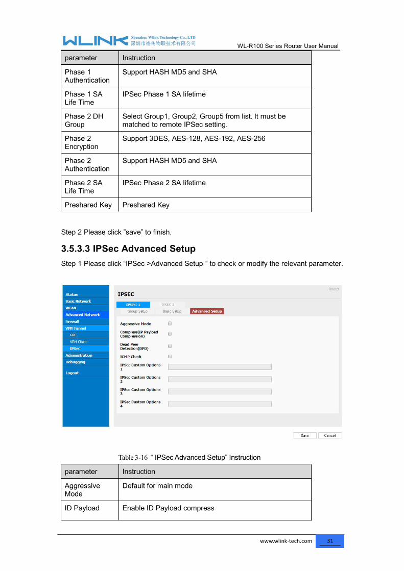
3.5.3.3 IPSec Advanced SetupStep 1 Please click “IPSec >Advanced Setup ” to check or modify the relevant parameter.
Table 3-16 “ IPSec Advanced Setup” Instruction
parameter Instruction
AggressiveMode
Default for main mode
ID Payload Enable ID Payload compress

WL-R100 Series Router User Manual
www.wlink-tech.com 32
parameter InstructionCompress
DPD To enable DPD service
ICMP ICMP Check for IPSec tunnel
IPSec CustomOptions
IPSec advanced setting such as left/right ID.
Step 2 Please click ”save” to finish.
----End
3.6 Administration
3.6.1 Identification SettingStep 1 Please click ”Administrator> Identification” to enter the GUI, you may modify the
router name, Host name and Domain name according to self-requirement.
Figure 3-16 Router Identification GUI
Table 3-17 “Router Identification” Instruction
Parameter Instruction
Router name Default is router, can be set maximum 32 character
Host name Default is router, can be set maximum 32 character
Domain name Default is empty, support maximum up to 32 character, it is
WL-R100 Series Router User Manual
www.wlink-tech.com 33
Parameter Instructionthe domain of WAN, no need to configure for mostapplication.
Step 2 Please click ”save” to finish
----End

WL-R100 Series Router User Manual
www.wlink-tech.com 34
3.6.2 Time SettingStep 1 Please click “Administrator> time” to check or modify the relevant parameter.
Figure 3-17 System Configuration GUI
If the device is online but time update is fail, please try other NTP Time Server.
Step 2 Please click “save to finish.
----End
WL-R100 Series Router User Manual
www.wlink-tech.com 35
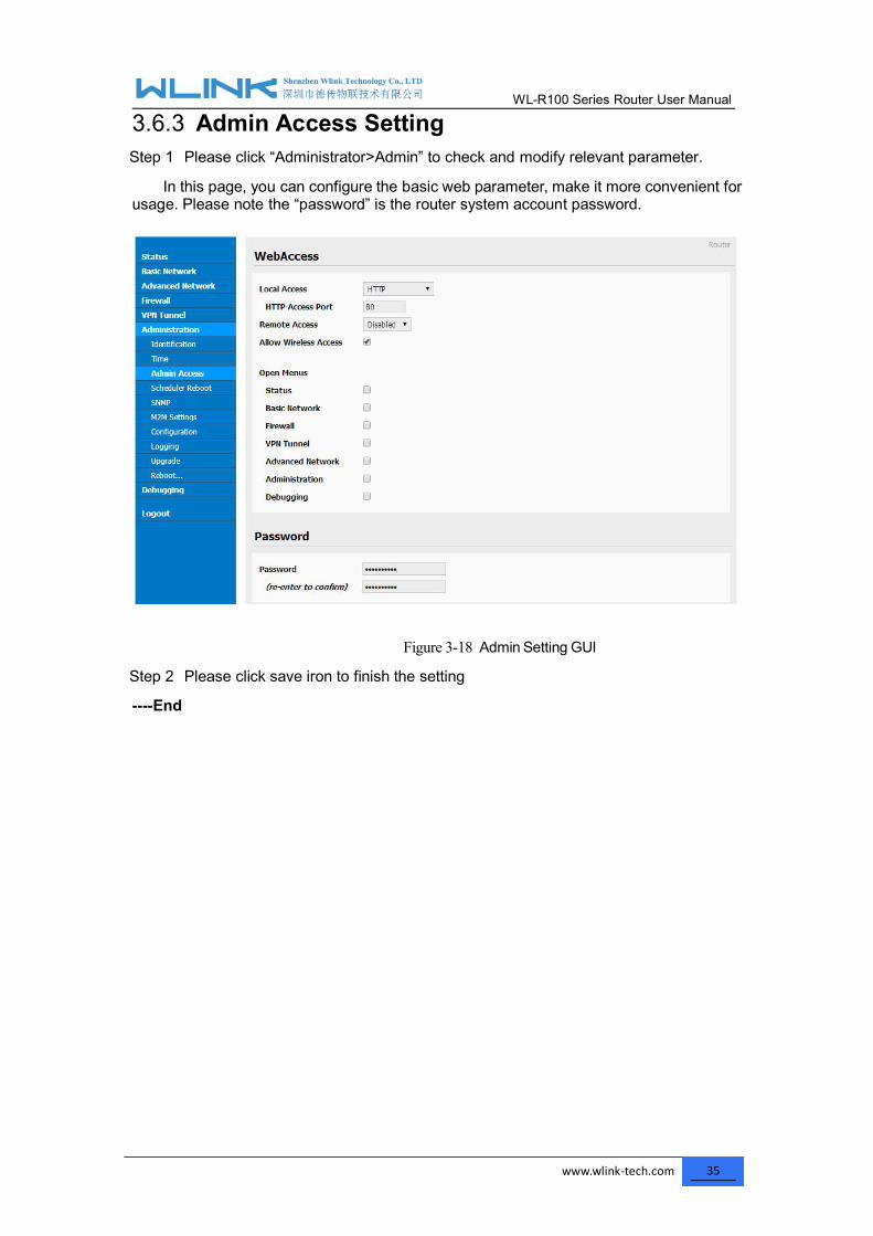
3.6.3 Admin Access SettingStep 1 Please click “Administrator>Admin” to check and modify relevant parameter.
In this page, you can configure the basic web parameter, make it more convenient forusage. Please note the “password” is the router system account password.
Figure 3-18 Admin Setting GUI
Step 2 Please click save iron to finish the setting
----End
WL-R100 Series Router User Manual
www.wlink-tech.com 36
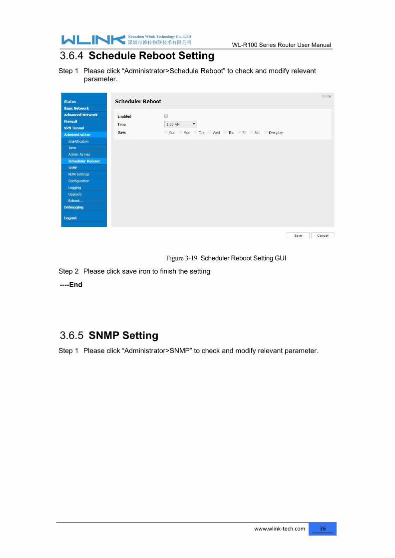
3.6.4 Schedule Reboot SettingStep 1 Please click “Administrator>Schedule Reboot” to check and modify relevant
parameter.
Figure 3-19 Scheduler Reboot Setting GUI
Step 2 Please click save iron to finish the setting
----End
3.6.5 SNMP SettingStep 1 Please click “Administrator>SNMP” to check and modify relevant parameter.

WL-R100 Series Router User Manual
www.wlink-tech.com 37
Figure 3-20 SNMP SettingGUI
Step 2 Please click save iron to finish the setting
----End
3.6.6 M2M Access Setting (Apply to M2M management platforminstallation application only)
Step 1 Please click “Administrator>M2M Access” to check and modify relevantparameter.

WL-R100 Series Router User Manual
www.wlink-tech.com 38
Figure 3-21 M2M Access Setting GUI
Step 2 Please click save iron to finish the setting
----End
3.6.7 Configuration SettingStep 1 Please click “ Administration> Configuration ” to do the backup setting
Figure 3-22 Backup and Restore Configuration GUI
Restore Default would lose all configuration information, please be careful.
Step 2 After setting the backup and restore configuration. The system will rebootautomatically.
----End

WL-R100 Series Router User Manual
www.wlink-tech.com 39
3.6.8 Logging SettingStep 1 Please click “Administrator> Logging” to start the configuration, you can set the file
path to save the log (Local or remote sever).
Figure 3-23 System log Setting GUI
Step 2 After configure, please click “Save” to finish.
----End

WL-R100 Series Router User Manual
www.wlink-tech.com 40
3.6.9 Firmware upgradeStep 1 Please click “Administrator>firmware upgrade” to open upgrade firmware tab.
Figure 3-24 Firmware Upgrade GUI
When upgrading, please don’t cut off the power.
3.6.10 System RebootStep 1 Please click “Administrator>Reboot” to restart the router. System will popup dialog
to remind “Yes” or “NO” before the next step.
Step 2 If choose “yes”, the system will restart, all relevant update configuration will beeffective after reboot.
----End
3.7 Debugging Setting3.7.1 Logs SettingStep 1 Please click “Debugging>Logs” to check and modify relevant parameter.

WL-R100 Series Router User Manual
www.wlink-tech.com 41
Figure 3-25 Logs GUI
Step 2 After configure, please click “Save” to finish.
----End
3.7.2 Ping SettingStep 1 Please click “Debugging>Logs” to check and modify relevant parameter.
Figure 3-26 Ping GUI
Step 2 After configure, please click “Save” to finish.
----End
3.7.3 Trace SettingStep 1 Please click “Debugging>Trace” to check and modify relevant parameter.
WL-R100 Series Router User Manual
www.wlink-tech.com 42
Figure 3-27 Trace GUI
Step 2 After configure, please click “Save” to finish.
----End

WL-R100 Series Router User Manual
www.wlink-tech.com 43
3.8 “RST” Button for Restore Factory SettingIf you couldn’t enter web interface for other reasons, you can also use this way.For R100 Series, “RST” button is on the left or Ethernet port, for R100 Series, the button ison the left of NET light. This button can be used when the router is in use or when therouter is turned on.Press the “RST” button and keep more than 8 seconds till the NET light stopping blink.The system will be restored to factory.
Table 3-18 System Default Instruction
Parameter Default setting
LAN IP 192.168.1.1
LAN Subnet Mask 255.255.255.0
DHCP server Enable
User Name admin
Password admin
After reboot, the previous configuration would be deleted and restore to factorysettings.
WL-R100 Series Router User Manual
www.wlink-tech.com 44
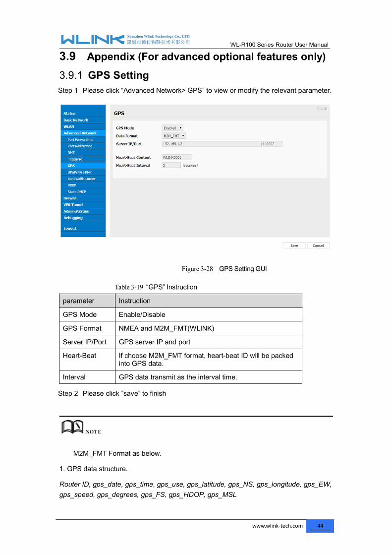
3.9 Appendix (For advanced optional features only)3.9.1 GPS SettingStep 1 Please click “Advanced Network> GPS” to view or modify the relevant parameter.
Figure 3-28 GPS Setting GUI
Table 3-19 “GPS” Instruction
parameter Instruction
GPS Mode Enable/Disable
GPS Format NMEA and M2M_FMT(WLINK)
Server IP/Port GPS server IP and port
Heart-Beat If choose M2M_FMT format, heart-beat ID will be packedinto GPS data.
Interval GPS data transmit as the interval time.
Step 2 Please click ”save” to finish
M2M_FMT Format as below.
1. GPS data structure.
Router ID, gps_date, gps_time, gps_use, gps_latitude, gps_NS, gps_longitude, gps_EW,gps_speed, gps_degrees, gps_FS, gps_HDOP, gps_MSL
WL-R100 Series Router User Manual
www.wlink-tech.com 45
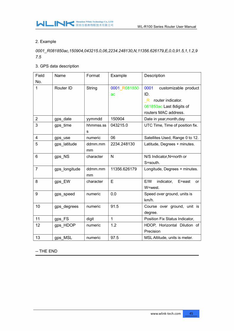
2. Example
0001_R081850ac,150904,043215.0,06,2234.248130,N,11356.626179,E,0.0,91.5,1,1.2,97.5
3. GPS data description
FieldNo.
Name Format Example Description
1 Router ID String 0001_R081850ac
0001 customizable productID._R router indicator.081850ac Last 8digits ofrouters MAC address.
2 gps_date yymmdd 150904 Date in year,month,day3 gps_time hhmmss.ss
s043215.0 UTC Time, Time of position fix.
4 gps_use numeric 06 Satellites Used, Range 0 to 12.5 gps_latitude ddmm.mm
mm2234.248130 Latitude, Degrees + minutes.
6 gps_NS character N N/S Indicator,N=north orS=south.
7 gps_longitude ddmm.mmmm
11356.626179 Longitude, Degrees + minutes.
8 gps_EW character E E/W indicator, E=east orW=west.
9 gps_speed numeric 0.0 Speed over ground, units iskm/h.
10 gps_degrees numeric 91.5 Course over ground, unit isdegree.
11 gps_FS digit 1 Position Fix Status Indicator,12 gps_HDOP numeric 1.2 HDOP, Horizontal Dilution of
Precision13 gps_MSL numeric 97.5 MSLAltitude, units is meter.
-- THE END