Embed Size (px)
Citation preview

8/14/2019 WLAN, Part 1 Contents
http://slidepdf.com/reader/full/wlan-part-1-contents 1/47
S-72.3240 Wireless Personal, Local, Metropolitan, and Wide Area Networks 1
WLAN, part 1
Contents
IEEE 802.11 WLAN architecture• Basic routing example
• IAPP and mobility management• Basic frame structure• MAC header structure• Usage of MAC address fields
Management framesSome IEEE 802.11 standard amendments

8/14/2019 WLAN, Part 1 Contents
http://slidepdf.com/reader/full/wlan-part-1-contents 2/47
S-72.3240 Wireless Personal, Local, Metropolitan, and Wide Area Networks 2
WLAN, part 1
IEEE 802.11 WLAN architecture
802.11 defines two BSS (Basic Service Set) options:
Infrastructure BSS Independent BSS(Ad-Hoc network)
APwiredLAN

8/14/2019 WLAN, Part 1 Contents
http://slidepdf.com/reader/full/wlan-part-1-contents 3/47
S-72.3240 Wireless Personal, Local, Metropolitan, and Wide Area Networks 3
WLAN, part 1
Infrastructure BSS
This is by far the most common way of implementing WLANs.
Infrastructure BSS
AP
The base stations connectedto the wired infrastructureare called access points (AP).
Wireless stations in anInfrastructure BSS mustalways communicate via the
AP (never directly).Before stations can use theBSS: Association .
wiredLAN

8/14/2019 WLAN, Part 1 Contents
http://slidepdf.com/reader/full/wlan-part-1-contents 4/47
S-72.3240 Wireless Personal, Local, Metropolitan, and Wide Area Networks 4
WLAN, part 1
Independent BSS
Mainly of interest for military applications.
Independent BSS(Ad-Hoc network)
No access point is required,stations can communicatedirectly.
Efficient routing of packetsis not a trivial problem(routing is not a task of
802.11).Ad-Hoc WLAN networks areoutside the scope of this course.

8/14/2019 WLAN, Part 1 Contents
http://slidepdf.com/reader/full/wlan-part-1-contents 5/47
S-72.3240 Wireless Personal, Local, Metropolitan, and Wide Area Networks 5
WLAN, part 1
Extended Service Set (ESS)
This is a larger WLAN network consisting of a number of BSS networks interconnected via a common backbone
AP AP AP
802.11 supports link-layer mobilitywithin an ESS (but not outside the ESS)

8/14/2019 WLAN, Part 1 Contents
http://slidepdf.com/reader/full/wlan-part-1-contents 6/47

8/14/2019 WLAN, Part 1 Contents
http://slidepdf.com/reader/full/wlan-part-1-contents 7/47
S-72.3240 Wireless Personal, Local, Metropolitan, and Wide Area Networks 7
WLAN, part 1
Distribution system (cont.)
For instance, when a wireless station moves from oneBSS to another, all nodes must update their databases, sothat the DS can distribute packets via the correct AP.
AP 1 AP 2
Router
WS
AP 1, AP 2 and router:update your databases!
Packets for this WS willnow be routed via AP 2.
Distribution System (DS)
WS moves to another BSS

8/14/2019 WLAN, Part 1 Contents
http://slidepdf.com/reader/full/wlan-part-1-contents 8/47
S-72.3240 Wireless Personal, Local, Metropolitan, and Wide Area Networks 8
WLAN, part 1
Basic routing example
When WS associates with AP 2, the router in charge of the IP subnet addressing obtains an IP address from theDHCP (Dynamic Host Configuration Protocol) server.
Router
AP 1 AP 2
Distribution System (DS)
DHCPServer
Association
Fetch IP address
1
2
1
2
Externalnetwork(LAN or
Internet)
WS

8/14/2019 WLAN, Part 1 Contents
http://slidepdf.com/reader/full/wlan-part-1-contents 9/47
S-72.3240 Wireless Personal, Local, Metropolitan, and Wide Area Networks 9
WLAN, part 1
Basic routing example (cont.)
The router must maintain binding between this IP addressand the MAC address of the wireless station.
Router
AP 1 AP 2
Distribution System (DS) Externalnetwork(LAN or
Internet)124.2.10.57
00:90:4B:00:0C:72
00:90:4B:00:0C:72 WS

8/14/2019 WLAN, Part 1 Contents
http://slidepdf.com/reader/full/wlan-part-1-contents 10/47
8/14/2019 WLAN, Part 1 Contents
http://slidepdf.com/reader/full/wlan-part-1-contents 11/47
S-72.3240 Wireless Personal, Local, Metropolitan, and Wide Area Networks 11
WLAN, part 1
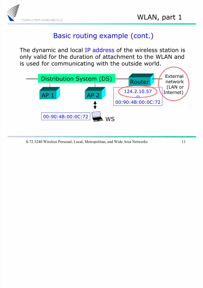
Basic routing example (cont.)
The dynamic and local IP address of the wireless station isonly valid for the duration of attachment to the WLAN andis used for communicating with the outside world.
Router
AP 1 AP 2
Distribution System (DS) Externalnetwork(LAN or
Internet)124.2.10.57
00:90:4B:00:0C:72
00:90:4B:00:0C:72 WS

8/14/2019 WLAN, Part 1 Contents
http://slidepdf.com/reader/full/wlan-part-1-contents 12/47
S-72.3240 Wireless Personal, Local, Metropolitan, and Wide Area Networks 12
WLAN, part 1
Basic routing example (cont.)
The router must also know (and use) the MAC address of the access point via which the packets must be routed.For this purpose, a special protocol (IAPP) is needed!
Router
AP 1 AP 2
Distribution System (DS) Externalnetwork(LAN or
Internet)124.2.10.57
00:90:4B:00:0C:7200:03:76:BC:0D:12
00:90:4B:00:0C:72
00:03:76:BC:0D:12
WS

8/14/2019 WLAN, Part 1 Contents
http://slidepdf.com/reader/full/wlan-part-1-contents 13/47
S-72.3240 Wireless Personal, Local, Metropolitan, and Wide Area Networks 13
WLAN, part 1
IAPP (Inter-Access Point Protocol)
IAPP (defined in IEEE 802.11f) offers mobility in the Datalink layer (within an ESS = Extended Service Set).
Router
AP 1 AP 3
Distribution System (DS) Externalnetwork(LAN or
Internet)AP 2
IAPP: APs must be able to communicatewith each other when the station movesaround in the WLAN
1
2

8/14/2019 WLAN, Part 1 Contents
http://slidepdf.com/reader/full/wlan-part-1-contents 14/47
S-72.3240 Wireless Personal, Local, Metropolitan, and Wide Area Networks 14
WLAN, part 1
In addition to IAPP …
IAPP alone is not sufficient to enable seamless handoversin a WLAN. The stations must be able to measure thesignal strengths from surrounding APs and decide when
and to which AP a handover should be performed (no802.11 standardised solutions are available for thisoperation).
In 802.11 networks, a handover means reassociating withthe new AP . There may be two kinds of problems:
• will handover work when APs are from different vendors?
• will handover work together with security solutions?

8/14/2019 WLAN, Part 1 Contents
http://slidepdf.com/reader/full/wlan-part-1-contents 15/47
S-72.3240 Wireless Personal, Local, Metropolitan, and Wide Area Networks 15
WLAN, part 1
Mobility Management (MM)
There are basically two objectives of Mobility Management:
MM offers seamless handovers when moving from one
network/subnetwork/BSS to another
MM makes sure that users or terminals can be reached
when they move to another network/subnetwork/BSS
1.
2.
Active network connection – handoverActive network connection – handover
Passive user/terminal – reachabilityPassive user/terminal – reachability

8/14/2019 WLAN, Part 1 Contents
http://slidepdf.com/reader/full/wlan-part-1-contents 16/47
S-72.3240 Wireless Personal, Local, Metropolitan, and Wide Area Networks 16
WLAN, part 1
MM in cellular wireless networks (1)
1. Handover: In a cellular wireless network (e.g. GSM),the call is not dropped when a user moves to anothercell. Handovers are based on measurements performed
by the mobile terminal and base stations.
BS 1 BS 2

8/14/2019 WLAN, Part 1 Contents
http://slidepdf.com/reader/full/wlan-part-1-contents 17/47
S-72.3240 Wireless Personal, Local, Metropolitan, and Wide Area Networks 17
WLAN, part 1
MM in cellular wireless networks (2)
VLR HLR
2. Reachability: In a cellular wireless network, the HLR (Home Location Register) knows in which VLR (VisitorLocation Register) area the mobile terminal is located.
The VLR then uses paging to find the terminal.Mobilesubscribernumberpoints to
HLRpoints to
Paging

8/14/2019 WLAN, Part 1 Contents
http://slidepdf.com/reader/full/wlan-part-1-contents 18/47
S-72.3240 Wireless Personal, Local, Metropolitan, and Wide Area Networks 18
WLAN, part 1
MM in cellular wireless networks (3)
3. IP services (e.g. based on GPRS): Reachability in thiscase is kind of a problem. Conventional IP services usethe client – server concept where reachability is not an
important issue.
Server
Client
Request
Response
Typical client - server transaction:

8/14/2019 WLAN, Part 1 Contents
http://slidepdf.com/reader/full/wlan-part-1-contents 19/47
S-72.3240 Wireless Personal, Local, Metropolitan, and Wide Area Networks 19
WLAN, part 1
MM in three different OSI layers
Mobility Management (MM) schemes are possible in threedifferent layers of the OSI protocol layer model:
Application layerApplication layer…………
Transport layerTransport layer
Network layerNetwork layerData link layerData link layerPhysical layerPhysical layer
e.g. SIP (Session Initiation Protocol)
e.g. Mobile IPIAPP (Inter-Access Point Protocol)
Terminal mobility
Personal mobility
Handovers

8/14/2019 WLAN, Part 1 Contents
http://slidepdf.com/reader/full/wlan-part-1-contents 20/47
S-72.3240 Wireless Personal, Local, Metropolitan, and Wide Area Networks 20
WLAN, part 1
MM in the Data link layer
Mobility Management (MM) schemes are possible in threedifferent layers of the OSI protocol layer model:
Application layerApplication layer…………
Transport layerTransport layer
Network layerNetwork layerData link layerData link layerPhysical layerPhysical layer
IAPP (IEEE 802.11f):Seamless roaming within anESS network (= IP subnet).
Handover is not possible when
moving from one ESS networkto another.
No reachability solutions.

8/14/2019 WLAN, Part 1 Contents
http://slidepdf.com/reader/full/wlan-part-1-contents 21/47

8/14/2019 WLAN, Part 1 Contents
http://slidepdf.com/reader/full/wlan-part-1-contents 22/47
S-72.3240 Wireless Personal, Local, Metropolitan, and Wide Area Networks 22
WLAN, part 1
MM in the Application layerMobility Management (MM) schemes are possible in threedifferent layers of the OSI protocol layer model:
Application layerApplication layer…………
Transport layerTransport layer
Network layerNetwork layerData link layerData link layerPhysical layerPhysical layer
SIP (or other applicationlayer solutions):
No seamless handovers assuch...
However, the terminal canbe reached from the outsidenetwork , like with Mobile IP.

8/14/2019 WLAN, Part 1 Contents
http://slidepdf.com/reader/full/wlan-part-1-contents 23/47
S-72.3240 Wireless Personal, Local, Metropolitan, and Wide Area Networks 23
WLAN, part 1
Mobility management summaryWithin a WLAN, handovers are possible (based on IAPP +proprietary solutions in equipment), but there is no IEEE-supported reachability solution available.
Handovers between different WLANs require Mobile IP(which offers also reachability). Unfortunately, Mobile IPincludes a non-transparent mechanism (Discovering Care-of Address) that must be implemented in all APs.
Global reachability of wireless stations can be achievedusing SIP or similar Application layer concepts. SIP doesnot require changes to APs.

8/14/2019 WLAN, Part 1 Contents
http://slidepdf.com/reader/full/wlan-part-1-contents 24/47
S-72.3240 Wireless Personal, Local, Metropolitan, and Wide Area Networks 24
WLAN, part 1
IEEE 802.11 frame structure
PSDU (PLCP Service Data Unit)
MAC H
PHY
MSDU (MAC SDU)
LLC payloadH
MAC
LLC
IP
IEEE 802
PHY H
IP packet
: :TCP/IP protocolsuite (usually)
PPDU (PLCP Protocol Data Unit)
MPDU (MAC Protocol Data Unit)

8/14/2019 WLAN, Part 1 Contents
http://slidepdf.com/reader/full/wlan-part-1-contents 25/47
S-72.3240 Wireless Personal, Local, Metropolitan, and Wide Area Networks 25
WLAN, part 1
PDU vs. SDU
IP
LLC
MAC
PHY
:
IP
LLC
MAC
PHY
:
PDU (Protocol Data Unit) is
sent between network nodes(in a specific protocol layer)
SDU (Service Data Unit) is sentbetween protocol layers
Payload of a PDU in layer N = SDU to/from the layer N+1

8/14/2019 WLAN, Part 1 Contents
http://slidepdf.com/reader/full/wlan-part-1-contents 26/47
S-72.3240 Wireless Personal, Local, Metropolitan, and Wide Area Networks 26
WLAN, part 1
Overall frame structure (application = HTML)
PSDU (PLCP Service Data Unit)
MAC H
PHY
MSDU (MAC SDU)
LLC payloadH
H IP payload
TCP payload
HTTP payload
HTML page
MAC
LLC
IP
TCP
HTTP
IEEE 802
TCP/IP
PHY H

8/14/2019 WLAN, Part 1 Contents
http://slidepdf.com/reader/full/wlan-part-1-contents 27/47
S-72.3240 Wireless Personal, Local, Metropolitan, and Wide Area Networks 27
WLAN, part 1
MAC header structure
MPDU (MAC Protocol Data Unit)
MAC payloadAddr 1 Addr 2 Addr 3 Addr 4(optional)
FCS
Frame Control field (type of frame & various flag bits)
Duration field(contains NAV value)
Sequence Control field(numbering of framesmodulo 4096)
One byte(eight bits)

8/14/2019 WLAN, Part 1 Contents
http://slidepdf.com/reader/full/wlan-part-1-contents 28/47
S-72.3240 Wireless Personal, Local, Metropolitan, and Wide Area Networks 28
WLAN, part 1
Content of Frame Control field
One bit
1 2 3 4 5 6 7 8Protocol Subt. of frameType …
Protocol: Indicates IEEE 802.11 MAC
Type: 00 (Management frames)01 (Control frames)10 (Data frames)
Subtype of frame: Describes type of management, control,or data frame in more detail (e.g. ACK => 1101)

8/14/2019 WLAN, Part 1 Contents
http://slidepdf.com/reader/full/wlan-part-1-contents 29/47
S-72.3240 Wireless Personal, Local, Metropolitan, and Wide Area Networks 29
WLAN, part 1
Flags in Frame Control field
One bit
1 2 3 4 5 6 7 8Protocol Subt. of frameType …
1: Bit is set if frame is sent to AP2: Bit is set if frame is sent from AP3: Used in fragmentation4: Bit is set if frame is retransmitted5: Power management bit (power saving operation)
6: More data bit (power-saving operation)7: Bit is set if WEP is used8: Strict ordering of frames is required

8/14/2019 WLAN, Part 1 Contents
http://slidepdf.com/reader/full/wlan-part-1-contents 30/47
S-72.3240 Wireless Personal, Local, Metropolitan, and Wide Area Networks 30
WLAN, part 1
Usage of MAC address fields
MPDU (MAC Protocol Data Unit)
Addr 1 Addr 2 Addr 3 Addr 4
Address 1: Receiver (wireless station or AP)Address 2: Sender (wireless station or AP)Address 3: Ultimate source/destination (router in DS)
Address 4: Only used inWireless Bridgesolutions:
LAN LANAPAP APAP

8/14/2019 WLAN, Part 1 Contents
http://slidepdf.com/reader/full/wlan-part-1-contents 31/47
S-72.3240 Wireless Personal, Local, Metropolitan, and Wide Area Networks 31
WLAN, part 1
Direction: AP => wireless station
Addr 1 Addr 2 Addr 3
Addr 1: Receiver (wireless station)Addr 2: Transmitter = BSSID (AP)Addr 3: Ultimate source (router)
AP
Router
BSSID: MAC address of APSSID: Alphanumeric name
of AP (or BSS) 1
23

8/14/2019 WLAN, Part 1 Contents
http://slidepdf.com/reader/full/wlan-part-1-contents 32/47
S-72.3240 Wireless Personal, Local, Metropolitan, and Wide Area Networks 32
WLAN, part 1
MAC addressing exampleFrames to the WS must also include the MAC address of the ”ultimate source” to which return frames should berouted (then ”ultimate destination”).
Router
AP 1 AP 2
Distribution System (DS) Externalnetwork
00:20:34:B2:C4:10
00:90:4B:00:0C:72
00:03:76:BC:0D:12
WS 1
23

8/14/2019 WLAN, Part 1 Contents
http://slidepdf.com/reader/full/wlan-part-1-contents 33/47
S-72.3240 Wireless Personal, Local, Metropolitan, and Wide Area Networks 33
WLAN, part 1
Direction: Wireless station => AP
Addr 1 Addr 2 Addr 3
Addr 1: Receiver = BSSID (AP)Addr 2: Transmitter (wireless station)Addr 3: Ultimate destination (router)
AP
Router
2
13

8/14/2019 WLAN, Part 1 Contents
http://slidepdf.com/reader/full/wlan-part-1-contents 34/47
S-72.3240 Wireless Personal, Local, Metropolitan, and Wide Area Networks 34
WLAN, part 1
Management frames
In addition to the data frames (containing the user datato be transported over the 802.11 network) and controlframes (e.g. acknowledgements), there are a number of
management frames.Note that these management frames compete for accessto the medium in equal terms (using CSMA/CA) with thedata and control frames.
Some of these management frames are presented onthe following slides.

8/14/2019 WLAN, Part 1 Contents
http://slidepdf.com/reader/full/wlan-part-1-contents 35/47

8/14/2019 WLAN, Part 1 Contents
http://slidepdf.com/reader/full/wlan-part-1-contents 36/47
S-72.3240 Wireless Personal, Local, Metropolitan, and Wide Area Networks 36
WLAN, part 1
Probe request & response frames
A probe request frame is transmitted from a wirelessstation during active scanning . Access points withinreach respond by sending probe response frames.
Probe request frames contain the following information:SSID (0 ... 32 bytes), alphanumeric “network name”
Bit rates supported by the station. This is used by APs tosee if the station can be permitted to join the network.
Probe response frames actually contain the same kind of “network information” as beacon frames.

8/14/2019 WLAN, Part 1 Contents
http://slidepdf.com/reader/full/wlan-part-1-contents 37/47

8/14/2019 WLAN, Part 1 Contents
http://slidepdf.com/reader/full/wlan-part-1-contents 38/47
S-72.3240 Wireless Personal, Local, Metropolitan, and Wide Area Networks 38
WLAN, part 1
Passive and active scanning
Wireless stations can find out about 802.11 networks byusing passive or active scanning.
During passive scanning , the station searches beaconframes, moving from channel to channel through thecomplete channel set (802.11b => 13 channels).
During active scanning , the station selects Channel 1and sends a probe request frame. If no probe response
frame is received within a certain time, the stationmoves to Channel 2 and sends a probe request frame,and so on.

8/14/2019 WLAN, Part 1 Contents
http://slidepdf.com/reader/full/wlan-part-1-contents 39/47
S-72.3240 Wireless Personal, Local, Metropolitan, and Wide Area Networks 39
WLAN, part 1
Case study 1: Station connecting to a WLAN
When a station moves into the coverage area of a WLAN,the following procedures take place:
1) Scanning: the station searches for a suitable channelover which subsequent communication takes place
2)
3)
4)
Association: the station associates with an AP
IP address allocation: the station gets an IP address,for instance from a DHCP server
Authentication: only if this security option isrequired.

8/14/2019 WLAN, Part 1 Contents
http://slidepdf.com/reader/full/wlan-part-1-contents 40/47
S-72.3240 Wireless Personal, Local, Metropolitan, and Wide Area Networks 40
WLAN, part 1
Case study 2: Handover to another AP
When a station has noticed that the radio connection toanother AP is a better than the existing connection:
1) Reassociation: the station associates with anotherAP
2) No new IP address is needed; however, the WLANmust be able to route downlink traffic via the new AP
3) Authentication: this security option, if required, will
result in a substantially increased handover delay(complete procedure sequence:deauthentication, disassociation, reassociation,authentication ).

8/14/2019 WLAN, Part 1 Contents
http://slidepdf.com/reader/full/wlan-part-1-contents 41/47
S-72.3240 Wireless Personal, Local, Metropolitan, and Wide Area Networks 41
WLAN, part 1
Some IEEE 802.11 standard amendments
f IAPP
eQoS
iSecurity
802.11 basic protocol
hDFS/TCP
dScanning
aOFDM 5GHz bDSSS 2.4GHz gOFDM 2.4GHz Physical layer
MAC layer

8/14/2019 WLAN, Part 1 Contents
http://slidepdf.com/reader/full/wlan-part-1-contents 42/47

8/14/2019 WLAN, Part 1 Contents
http://slidepdf.com/reader/full/wlan-part-1-contents 43/47
S-72.3240 Wireless Personal, Local, Metropolitan, and Wide Area Networks 43
WLAN, part 1
IEEE 802.11f
f IAPP
eQoS
iSecurity
802.11 basic protocol
hDFS/TCP
dScanning
aOFDM 5GHz bDSSS 2.4GHz gOFDM 2.4GHz
The objective: to specify theInter-Access Point Protocol
(IAPP) that enables seamlessroaming between differentAccess Points within an ESS.
Note: 802.11f is not concernedwith roaming between ESSnetworks. For this purpose, non-802.11 solutions must be used.

8/14/2019 WLAN, Part 1 Contents
http://slidepdf.com/reader/full/wlan-part-1-contents 44/47
S-72.3240 Wireless Personal, Local, Metropolitan, and Wide Area Networks 44
WLAN, part 1
IEEE 802.11e
f IAPP
eQoS
iSecurity
802.11 basic protocol
hDFS/TCP
dScanning
aOFDM 5GHz bDSSS 2.4GHz gOFDM 2.4GHz
Quality of Service(QoS) for better
handling of voicetraffic, by findingways of minimizing
jitter and delayvariations andmaximising accesspoint throughput.

8/14/2019 WLAN, Part 1 Contents
http://slidepdf.com/reader/full/wlan-part-1-contents 45/47
S-72.3240 Wireless Personal, Local, Metropolitan, and Wide Area Networks 45
WLAN, part 1
IEEE 802.11i
f IAPP
eQoS
iSecurity
802.11 basic protocol
hDFS/TCP
dScanning
aOFDM 5GHz bDSSS 2.4GHz gOFDM 2.4GHz
Security issues suchas TKIP (Temporary
Key IntegrityProtocol) e.g. forimproved keymanagement, and802.1x for
authentication(note: can also beused in wired LAN).

8/14/2019 WLAN, Part 1 Contents
http://slidepdf.com/reader/full/wlan-part-1-contents 46/47
S-72.3240 Wireless Personal, Local, Metropolitan, and Wide Area Networks 46
WLAN, part 1
IEEE 802.11h
f IAPP
eQoS
iSecurity
802.11 basic protocol
hDFS/TCP
dScanning
aOFDM 5GHz bDSSS 2.4GHz gOFDM 2.4GHz
Transmit PowerControl (TPC) &
Dynamic FrequencySelection (DFS):
Required in Europefor WLAN systemsoperating in the 5
GHz band.

8/14/2019 WLAN, Part 1 Contents
http://slidepdf.com/reader/full/wlan-part-1-contents 47/47
S-72 3240 Wireless Personal Local Metropolitan and Wide Area Networks 47
WLAN, part 1
IEEE 802.11d
f IAPP
eQoS
iSecurity
802.11 basic protocol
hDFS/TCP
dScanning
aOFDM 5GHz bDSSS 2.4GHz gOFDM 2.4GHz
802.11d supplementsthe MAC layer to
promote worldwideusage of 802.11networks (throughfurther developmentof active & passivescanning schemes).


![NTENTS CONTENTS CONTENTS CONTENTS CONTENT · 2 NTENTS CONTENTS CONTENTS CONTENTS CONTENT Speaking Part 1 / Part 2 6 Listening Part 1 / Part 2 8 Writing Letter [Informal] 9 Unit 1](https://img.dokumen.tips/doc/110x75/5ae7fb077f8b9a3d3b8f4ab4/ntents-contents-contents-contents-content-ntents-contents-contents-contents-content.jpg)