Embed Size (px)
Citation preview

WLAN acc. RED
Wireless devices:
Normative requirements and test cases when
operating in 2.4 GHz and 5 GHz band

WLAN acc. RED; Test Method Examples 2
Introduction
Declaration of Conformity
Market Surveillance
Notified Bodies
Essential Requirements
Test Methods

Declaration of Conformity
3
Applied harmonized standardsand or other technical specifications
Who declares?
What item?
Identification of the apparatus
..in conformity with directive……2014/35/EU (=LVD)2014/53/EU (=RED)
Notified Body (NB) involved in conformity assessment
2014/30/EU (=EMCD)
Applicable for radio equipment: NB must be involved if the harmonized standard used is not referring to art. 3.2 of 2014/53/EU, if no harmonized standard is used, if test methods are changed, etc.The manufacturer can do the conformity assessment without NB, if in every respect a harmonized standard with referrence to RED can be applied.
From June 13, 2017 no reference to R&TTE any more!
WLAN acc. RED; Test Method Examples

Declaration of Conformity Example by Google
4
Who declares?
What item?
Identification of the apparatus
..in conformity with directive……2014/35/EU (=LVD)2014/53/EU (=RED)
Notified Body (NB) involved in conformity assessment
2014/30/EU (=EMCD)
Notified Body with ID #0560 =
On page 2 � Applied harmonized standards and or other technical specifications
Telefication B.V. also trading under the names KiwaTelefication and Kiwa EMCEdisonstraat 12A6902 PK ZEVENAARNetherlands
WLAN acc. RED; Test Method Examples
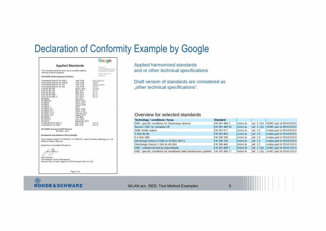
Declaration of Conformity Example by Google
5
Applied harmonized standardsand or other technical specifications
Draft version of standards are considered as „other technical specifications“.
Overview for selected standards
WLAN acc. RED; Test Method Examples

Declaration of Conformity Example by Fujitsu with Photos
6
There has no NB been involved in the conformity assessment.
The head lines help to refer to the essential requirements of the RED in a more structured way.
WLAN acc. RED; Test Method Examples

Advanced Search in ETSI Portal
7WLAN acc. RED; Test Method Examples

Advanced Search in ETSI Portal
8WLAN acc. RED; Test Method Examples

Advanced Search \ Technical Body \ BRAN
9WLAN acc. RED; Test Method Examples

Advanced Search: Details and Download
10WLAN acc. RED; Test Method Examples

Advanced Search: Details and Download \ Current Status
11WLAN acc. RED; Test Method Examples

Advanced Search: Details and Download \ Current Status
12WLAN acc. RED; Test Method Examples

RED, Article 4: Information on the Compliance
13
DoC
REDArt. 3
Conformity Assessment
Result=DoC
Combination of Radio Equipment &
Software
Precisly identified combination ofradio equipment and software
Art. 17
Annex VI
Essential Requirementsof Art. 3 are met
yes no
including dated reference to..harmonized standard or
to other technical specification
Precondition
- Test Reports- Documentation
- Solutions adopted to meetthe essential requirements
- and more
Manufacturer(sole responsible)
Notified bodies can be approached for consultance, testing, conformity assessment.NBs must be registered with a number and listed in the „NANDO“ list
WLAN acc. RED; Test Method Examples

List of Notified Bodies
14
2017-05-08-Downloaded-List-of-NBs-index.pdf
External file
WLAN acc. RED; Test Method Examples

Market Surveillance by TCAM / ADCO
15
ADCO / TCAM
Check of test reports,Check of DoCsPurchase of radio equipmentTest of radio equipment
Regulators of the EU + EFTA member states
DoCDUT identificationList of applied standards
Investi-gates
on random
Mismatch?Indication and
information exchangebetween member states
The last ADCO report has been a summary of the investigations of following 23 members:
Austria, Bulgaria, Cyprus, Estonia, Finland, France, Germany, Greece, Italy, Lithuania, Luxembourg, Malta, Netherlands, Norway, Poland, Portugal, Romania, Slovakia, Slovenia, Spain, Sweden, Switzerland, and United Kingdom
TCAM: Telecommunication Conformity Assessment and Market Surveillance Committee. 3+ meetings per year.
ADCO: Group of ADministrative CooperationADCO supports and complements work of TCAM.Common data base.
WLAN acc. RED; Test Method Examples

Essential Requirements: How the Harmonized Standards refer to RED articles 3.x
16
Article 3 of 2014/53/EU
Essential Requirements
Specific(art. 3.3)
Health &Safety
(art. 3.1a)
Radio(art. 3.2)
EMC (art. 3.1b)
If the radio equipment complies to anapplicable harmonized standardwith reference to directive 2014/53/EU then the radio equipment is presumed to be in conformity with the essential requirements set out in article 3.2 of the RED.
If the radio equipment complies to an applicable harmonized EMC standardwith reference to directive 2014/53/EU then the radio equipment is presumed to be in conformity with the essential requirements set out in article 3.1 b of the RED.
Article 3 of the RED has an „umbrella“ function.
WLAN acc. RED; Test Method Examples

Art. 3.2 for Radio
Scenario for DoC
17
R&TTE = 99/5/EC
Art. 3.1 (b) for EMC
Art. 3.2 for Radio
Art. 3.1 (b) for EMC
H.S.Version
xy
Scenario Description:
Harmonized Standard Version xy refers to R&TTE
New version >xy already published.before 13 June 2017..
H.S.Version
>xy
before 13 June 2017 *) 13 June 2017
Target Date: Citation in the Official Journal of the EU
H.S. Version xy can be applied
H.S. Version >xy to be applied
*) individual date per standard
RED = 2014/53/EU
ETSI Work Programme
See description below!
STOP!No reference to R&TTEfor market placements from June 13, 2017.
Reference to …
Reference to …
WLAN acc. RED; Test Method Examples

Test Methods
18
In order to show conformity with the essential requirements set out in the radio part (in art. 3.2) of the RED typically following test methods can be applied. The individual harmonizedstandard specifies technical parameters, limits, etc. where applicable.
Summary from H. Mellein, R&S News 215
WLAN acc. RED; Test Method Examples

19
Test Methods
Wireless devices:
Normative requirements and test cases
when operating in 2.4 GHz and 5 GHz band
WLAN acc. RED; Test Method Examples

20
Examples of wireless equipment
WLAN acc. RED; Test Method Examples

21
Why is Regulation necessary?
Regulation
radiated electromagnetic waves as Radio Frequencies are limited natural resources
� therefore usually the usage of electromagnetic waves is right of the state
governmental applications
civil applications
ITU regulates all frequencies from 9 kHz to 400 GHz
WLAN acc. RED; Test Method Examples

22
The role of ISM Bands
Intended emissions• Radio communication• Industrial Scientific Medical (ISM) equipment ISM
Unintended emissions• household appliances, electric tools, electrical lighting, automotive,
information and telecommunication technology, and multimedia equipment, radio and TV receivers EMI
WLAN acc. RED; Test Method Examples

EU Directive 2014/53/EU
23
RED
WLAN acc. RED; Test Method Examples

24
Data transmission equipment operating in the 2.4 GHz ISM band 5 GHz high performance RLAN
WLAN acc. RED; Test Method Examples

ETSI EN 300 328
Test Cases
25
RF output power
Duty cycle, Tx-sequence, Tx-gap
Accumulated Transit Time, Frequency Occupation and Hopping Sequence
Hopping Frequency Separation
Medium Utilization (MU) factor
Adaptivity
Occupied Channel Bandwidth
Transmitter unwanted emissions in the out-of-band domain
Transmitter unwanted emissions in the spurious domain
Receiver spurious emissions
Receiver Blocking
Geo-location capacity
WLAN acc. RED; Test Method Examples

ETSI EN 301 893
Test Cases
26
Center Frequencies
Nominal Channel Bandwidth and occupied Channel Bandwidth
RF output power, Transit Power Control (TPC) and power density
Transmitter unwanted transmissions
Receiver spurious transmissions
Dynamic Frequency Selection (DFS)
Adaptivity
Receiver Blocking
User Access Restriction
Geo-location capacity
WLAN acc. RED; Test Method Examples

RF Output Power
ı a fast power sensor suitable for 2.4 GHz and capable of 1 MS/s must be used. ı The measurement duration is defined for both non-adaptive and adaptive equipment, in order to
improve accuracy. While either the radiated or conducted measurement method can be used, they all need to follow similar data acquisition steps to obtain the results. For conducted measurement on devices with one transmit chain � sample the transmit signal, and store the raw data� For conducted measurements on devices with multiple transmit chains � measurements
need to be made at all transmit ports simultaneously, and the power of the individual samples of all ports needs to be stored and summed.
� For radiated measurements, the DUT must be configured and antenna(s) positioned for maximum e.i.r.p. levels towards the measuring antenna, including smart antenna systems and systems capable of beam forming. The fast power sensor is also required for the measurement; a spectrum analyzer should not be used.
27WLAN acc. RED; Test Method Examples

RF Output Power
ı The start and stop times of each burst are stored, and should be used to calculate the RMS (Root Mean Square) power over the burst period. The maximum e.i.r.p. calculation to determine the RF Output Power (P) sums three measured values, the highest Pburst value (A), antenna assembly gain (G) and the additional beam forming gain (Y), as given by the formula:
P = A + G + Yı The required measurement time is equipment dependent and could be more than 12s. ı Example: 830 hopping frequencies x 15ms dwell time = 12450ms ı With 1MS the data to handle is 12.45 million measurements per port. 49.8 million
measurements for a four port MIMO device
28WLAN acc. RED; Test Method Examples

RF Output Power
29WLAN acc. RED; Test Method Examples

Medium Utilization (MU) factor
ı shall only be performed for non-adaptive equipmentı For each burst calculate the product of (Pburst / 100 mW) and the TxOn time. Pburst is expressed
in mW. TxOn time is expressed in ms
MU = (P / 100 mW) × DC
ı Medium Utilization is the sum of all these products divided by the observation period (expressed in ms). This value, which shall comply with the limit shall be recorded in the test report.
ı If operation without blacklisted frequencies is not possible, the power of the bursts on blacklisted hopping frequencies (for the calculation of the Medium Utilization) is assumed to be equal to the average value of the RMS power of the bursts on all active hopping frequencies.
30WLAN acc. RED; Test Method Examples

Medium Utilization (MU) factor
31WLAN acc. RED; Test Method Examples

Duty cycle, Tx-sequence, Tx-gap
ı shall only be performed for non-adaptive equipmentı The start and stop times are defined as the points where the power is at least 30 dB below the
highest value of the stored samplesı The observation period is equal to ‘the average dwell time multiplied by 100’ or ‘the average
dwell time multiplied by 2 times the number of hopping sequences (N)’ (whichever is greater)ı Duty Cycle (DC) is the sum of all TxOn times between the end of the first gap (which is the start
of the first burst within the observation period) and the start of the last burst (within this observation period) divided by the observation period
ı For equipment using blacklisting, the TxOn time measured for a single (and active) hopping frequency shall be multiplied by the number of blacklisted frequencies. This value shall be added to the sum calculated above.
ı For non-adaptive FHSS equipment, the Duty Cycle shall be equal to or less than the maximum value declared by the manufacturer. In addition, the maximum Tx-sequence time shall be 5 mswhile the minimum Tx-gap time shall be 5 ms.
32WLAN acc. RED; Test Method Examples

Duty cycle, Tx-sequence, Tx-gap
33WLAN acc. RED; Test Method Examples

Power spectral density
ı Connect the DUT to the spectrum analyzer and use the specified settingsı Repeat the measurement for each of the transmit ports. For each sampling point (frequency
domain), add up the coincident power values (in mW) for the different transmit chains and use this as the new data set
ı Add up the values for power for all the samples in the file using the formula below:
���� = ∑ ����� � ���
with k being the total number of samples and n the actual sample numberı Normalize the individual values for power (in dBm) so that the sum is equal to the RF Output
Power (e.i.r.p.) measured beforeı Starting from the first sample PSamplecorr(n) (lowest frequency), add up the power (in mW) of
the following samples representing a 1 MHz segment and record the results for power and position (i.e. sample #1 to sample #100). This is the Power Spectral Density (e.i.r.p.) for the first 1 MHz segment which shall be recorded.
34WLAN acc. RED; Test Method Examples

Power spectral density
35WLAN acc. RED; Test Method Examples

Accumulated Transit Time, Frequency Occupation and Hopping
Sequenceı The output of the transmitter shall be connected to a spectrum analyzer or equivalent. The
analyzer shall be set as specified.ı Identify the data points related to the frequency being investigated by applying a thresholdı Count the number of data points identified as resulting from transmissions on the frequency
being investigated and multiply this number by the time difference between two consecutive data points
ı The result is the Accumulated Transmit Time which shall comply with the limit and which shall be recorded in the test report
ı Complying with the Frequency Occupation requirement:� Make the following changes on the analyzer and repeat the steps
Sweep time: 4 × Dwell Time × Actual number of hopping frequencies in use Example : 4 x 10ms x 830 = 33.2s, with 32000 sweep points of the analyzer the resolution is < 1ms, bursts may be 100µs or less � HD measurement required
36WLAN acc. RED; Test Method Examples

Hopping Frequency Separation
ı Standard gives two optionsı The output of the transmitter shall be connected to a spectrum analyzer or equivalent. The
analyzer shall be set as specified.ı Use the marker function of the analyzer to define the frequencies corresponding to the lower -
20 dBr point and the upper -20 dBr point for both hopping frequencies F1 and F2. This will result in F1L and F1H for hopping frequency F1 and in F2L and F2H for hopping frequency F2. These values shall be recorded in the report
ı Calculate the center frequencies F1C and F2C for both hopping frequencies using the formulas below. These values shall be recorded in the report
�1� =�������
� �2� =
�������
�
ı Calculate the Hopping Frequency Separation (FHS) using the formula below. This value shall be recorded in the report
��� = �2� − �1�
37WLAN acc. RED; Test Method Examples

Hopping Frequency Separation
ı Compare the measured Hopping Frequency Separation with the limit defined. In addition, for non-Adaptive Frequency Hopping equipment, the Hopping Frequency Separation shall be equal to or greater than the Occupied Channel Bandwidth
FHS ≥ Occupied Channel Bandwidth
38WLAN acc. RED; Test Method Examples

Adaptivity
ı The DUT shall connect to a companion device during the test. The interference signal generator, the unwanted signal generator, the spectrum analyzer, the DUT and the companion device are connected using a set-up equivalent to the example given below
39WLAN acc. RED; Test Method Examples
Adaptivity
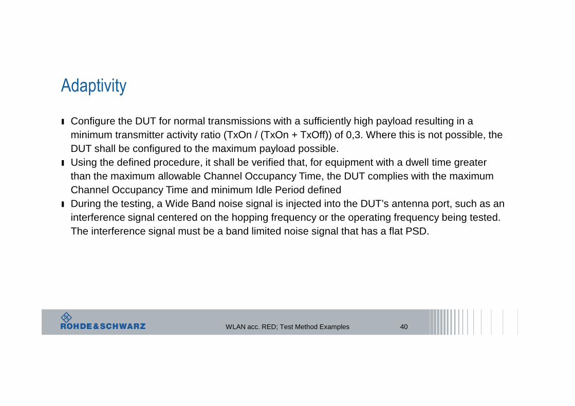
ı Configure the DUT for normal transmissions with a sufficiently high payload resulting in a minimum transmitter activity ratio (TxOn / (TxOn + TxOff)) of 0,3. Where this is not possible, the DUT shall be configured to the maximum payload possible.
ı Using the defined procedure, it shall be verified that, for equipment with a dwell time greater than the maximum allowable Channel Occupancy Time, the DUT complies with the maximum Channel Occupancy Time and minimum Idle Period defined
ı During the testing, a Wide Band noise signal is injected into the DUT’s antenna port, such as an interference signal centered on the hopping frequency or the operating frequency being tested. The interference signal must be a band limited noise signal that has a flat PSD.
40WLAN acc. RED; Test Method Examples

Adaptivity
41WLAN acc. RED; Test Method Examples

Adaptivity
42WLAN acc. RED; Test Method Examples

Transmitter unwanted emissions in the out-of-band domainı This measurement is performed by using the Time Domain Power Measurement function on a
spectrum analyzerı The measurement detector is set for RMS, and at least 5000 sweep points are required. The
measurement frequency range depends on the DUT’s Operating Bandwidthı With a Resolution Bandwidth of 1 MHz and SPAN set to 0 Hz, the Time Domain Power
measurement needs to be repeated at each center frequency that is 1MHz from the edge of each defined ISM (Industrial, Scientific and Medical) band frequency range
ı Similar to the RF output power measurement, the declared antenna assembly gain “G” in dBimust be added to the results for each of the 1 MHz segments
ı For equipment with multiple transmit chains, the measurements need to be repeated for each of the active transmit chains. The highest value in each 1 MHz segment is the highest transmitter spurious emissions in the OOB domain
ı Final measurement in time domain power means setting markers to start and end of each individual burst and evaluate it
ı Example: 20MHz WIFI � 240 measurements with several bursts in each measurement
43WLAN acc. RED; Test Method Examples

Transmitter unwanted emissions in the out-of-band domain
44WLAN acc. RED; Test Method Examples

Transmitter unwanted emissions in the spurious domain
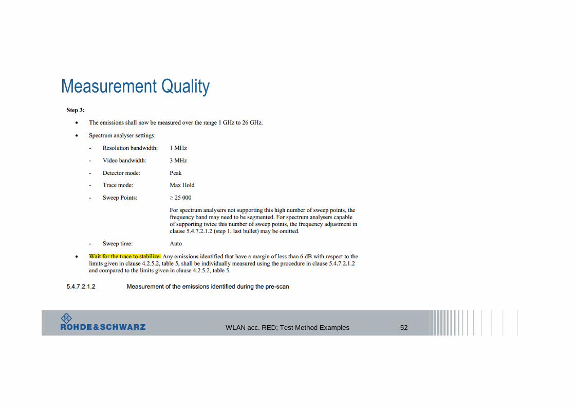
ı In a first step a pre-scan is performed to identify the emissions over the range 30 MHz to 1 000 MHz and over the range 1GHz to 12,75GHz
ı After that the individual unwanted emissions identified during the pre-scan measurements are accurately measured. This method assumes the spectrum analyzer has a Time Domain Power function.
ı Set a window where the start and stop indicators match the start and end of the burst with the highest level and record the value of the power measured within this window. If the spurious emission to be measured is a continuous transmission, the measurement window shall be set to match the start and stop times of the sweep
ı The value shall be compared to the defined limits
45WLAN acc. RED; Test Method Examples

Transmitter unwanted emissions in the spurious domain
46WLAN acc. RED; Test Method Examples

Receiver spurious emissions
ı In a first step a pre-scan is performed to identify the emissions over the range 30 MHz to 1 000 MHz and over the range 1GHz to 12,75GHz
ı After that the individual unwanted emissions identified during the pre-scan measurements are accurately measured. This method assumes the spectrum analyzer has a Time Domain Power function.
ı Set a window where the start and stop indicators match the start and end of the burst with the highest level and record the value of the power measured within this window. If the spurious emission to be measured is a continuous transmission, the measurement window shall be set to match the start and stop times of the sweep
ı The value shall be compared to the defined limits
47WLAN acc. RED; Test Method Examples

Receiver blockingı Measurement requirement may provide the biggest challenge for compliance. Since this testing
is a new requirement most equipment and manufacturers do not have readily available test setup and firmware to support this testing.
ı To properly exercise and evaluate this testing customers must be able to monitor Packet Error Rate (PER), ideally conducted through the antenna port, on all data rates/ modes of operation.
48WLAN acc. RED; Test Method Examples
Receiver blocking
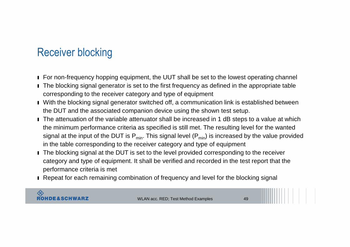
ı For non-frequency hopping equipment, the UUT shall be set to the lowest operating channelı The blocking signal generator is set to the first frequency as defined in the appropriate table
corresponding to the receiver category and type of equipmentı With the blocking signal generator switched off, a communication link is established between
the DUT and the associated companion device using the shown test setup. ı The attenuation of the variable attenuator shall be increased in 1 dB steps to a value at which
the minimum performance criteria as specified is still met. The resulting level for the wanted signal at the input of the DUT is Pmin. This signal level (Pmin) is increased by the value provided in the table corresponding to the receiver category and type of equipment
ı The blocking signal at the DUT is set to the level provided corresponding to the receiver category and type of equipment. It shall be verified and recorded in the test report that the performance criteria is met
ı Repeat for each remaining combination of frequency and level for the blocking signal
49WLAN acc. RED; Test Method Examples

Channel Access Mechanism
50WLAN acc. RED; Test Method Examples

Channel Access Mechanism
51WLAN acc. RED; Test Method Examples
Measurement Quality
52WLAN acc. RED; Test Method Examples

Measurement Quality
53WLAN acc. RED; Test Method Examples

Manufacturers’ responsibilities
under the REDV1.9.1 weglassen
WLAN acc. RED; Test Method Examples

55
OSP-B157
Spectrum Analyzer
Signal Generator
Vector Signal Generator
System Design: Overview
WMS32 & EMC32-K97x Software and Controller
WLAN acc. RED; Test Method Examples

56
TS8997 new Module OSP-B157W coming soon
WLAN acc. RED; Test Method Examples


![ACC List of Exhibits [unredacted] .pdf](https://img.dokumen.tips/doc/110x75/5868d1441a28ab68408c1499/acc-list-of-exhibits-unredacted-pdf.jpg)
