Embed Size (px)
Citation preview
Department of Electrical and Communications Engineering
WLAN-3G Interworking for future high data rate networks Mohammad Abualreesh
Master’s Thesis Thesis submitted in partial fullfilment of the requirement for the degree of Master of Science in Engineering Supervisor Prof. Sven-Gustav Häggman Instructor Lic. Naser Tarhuni
Mohammad Abualreesh 1 (81)

Master’s Thesis WLAN-3G Interworking for future high data rate networks
Author: Mohammad Abualreesh
Name of Thesis: WLAN-3G Interworking for future high data rate net-works
Date: 8.200816/ Espoo, Finland
Number of Pages: 81
Department: Electrical and Communications Engineering
Professorship: Communication Engineering
Supervisor: Prof. Sven-Gustav Häggman
Instructor: Lic. Naser Tarhuni
Abstract
Advanced wireless mobile communication systems such as 3rd Generation (3G) provide users high mobility but less data rate. On the other hand, WLAN systems offer high data rate with less mobility. However, there is a need for public wireless access: to cover the increasing demand for high data-intensive applications and to enable smooth online access to corpo-rate data services in hot spots. Therefore, one possibility to supply this need could be achieved through the interworking between both technolo-gies, i.e., WLAN-3G interworking together.
The main focus is to present and describe WLAN-3G interworking: aims, features, architectural methods, and development for future high data rate networks. In addition, the research provides an analytical model and a simulated model that can be used for evaluating the performance of the mobile IP method, the gateway method, and the emulator method which are used to implement WLAN-3G interworking.
As a consequence, the mobile IP method suffers from high handover de-lay. The gateway method has lower handover delay than the mobile IP method. However, the emulator method has the lowest handover delay.
Keywords: WLAN, 3G, UMTS, WCDMA, Interworking, Architecture
Mohammad Abualreesh 2 (81)

Master’s Thesis WLAN-3G Interworking for future high data rate networks
ACKNOWLEDGMENT
In the name of the God, Most Gracious, Most Merciful
بسم الله الرحمن الرحيم
E-mail: [email protected]
Phone: +358 50 487 2882
Mohammad Abualreesh
Lintukorventie 2K 119 02660, Espoo Finland
Espoo, August 2006
Finally I would like to express my special thanks and gratitude to my dearest parents, sisters (especially Samya), brothers, and all of my lovely people in Jordan, Palestine, Iraq, Lebanon and Finland (especially Aija) for their sincere supplication, feelings, love and continuous support throughout the whole master study and the work with this thesis.
I would like to express my thanks to the examiners of this thesis, Profes-sor Sven-Gustav Häggman and Naser Tarhuni (Licentiate Docent) of Helsinki University of Technology for their guidance during my thesis work.
This master’s thesis has been written for Communications Laboratory at Helsinki University of Technology.
Mohammad Abualreesh 3 (81)
Master’s Thesis WLAN-3G Interworking for future high data rate networks
Contents
1. INTRODUCTION .....................................................................................8 1.1 Background..............................................................................................8 1.2 Problem Background ...............................................................................8 1.3 Thesis Scope ...........................................................................................9 1.4 Objectives ................................................................................................9 1.5 Method .....................................................................................................9 1.6 Thesis Structure.......................................................................................9
2. 3G TELECOM NETWORK ....................................................................11 2.1 Background............................................................................................11 2.2 What is 3G .............................................................................................12 2.2.1 3G Definition ..........................................................................................12 2.2.2 3G Standards.........................................................................................13 2.2.3 3G Spectrum..........................................................................................14 2.3 3G Network ............................................................................................14 2.4 3G Services ...........................................................................................16 2.5 Summary................................................................................................17
3. WLAN TELECOM NETWORK...............................................................18 3.1 Background............................................................................................18 3.2 What is WLAN........................................................................................18 3.2.1 WLAN Definition.....................................................................................19 3.2.2 WLAN Benefits.......................................................................................19 3.2.3 WLAN Standards ...................................................................................20 3.3 WLAN Network Models..........................................................................21 3.3.1 WLAN Network Architectures ................................................................21 3.3.2 Medium Access Method.........................................................................22 3.4 WLAN Services......................................................................................22 3.5 Summary................................................................................................23
4. 3G FOR WLAN ......................................................................................24 4.1 On The Future High Data Rate Wireless Networks Vision.....................24 4.1.1 Starting From 3G ...................................................................................24 4.1.2 Is 3G Enough .........................................................................................25 4.1.3 Addressing WLAN..................................................................................26 4.1.4 Key Objectives .......................................................................................27 4.1.5 Future Vision..........................................................................................27 4.2 3G vs. WLAN .........................................................................................28 4.3 Thinking Towards The Interworking Between 3G & WLAN ...................31 4.4 Summary................................................................................................32
5. WLAN-3G INTERWORKING ARCHITECTURE METHODS .............................................................................................33
5.1 WLAN-3G Interworking General Overview ............................................34 5.1.1 Definition ................................................................................................34 5.1.2 The Big Picture ......................................................................................34 5.2 WLAN-3G Interworking Architectural Methods ......................................36 5.2.1 The Mobile IP Architectural Method.......................................................36 5.2.1.1 Handover ...............................................................................................37 5.2.1.2 Pros & Cons...........................................................................................39 5.2.2 The Gateway Architectural Method........................................................39 5.2.2.1 Handover ...............................................................................................40
Mohammad Abualreesh 4 (81)
Master’s Thesis WLAN-3G Interworking for future high data rate networks
5.2.2.2 Pros & Cons...........................................................................................43 5.2.3 The Emulator Architectural Method .......................................................43 5.2.3.1 Handover ...............................................................................................44 5.2.3.2 Pros & Cons...........................................................................................46 5.2.4 Other Possible Architectural Methods....................................................46 5.3 Summary................................................................................................47
6. SIMULATION & EVALUATION..............................................................48 6.1 QoS of Wireless Networks .....................................................................48 6.1.1 Wireless Topology .................................................................................48 6.1.2 Mobility...................................................................................................49 6.1.3 Bit Error Rate .........................................................................................49 6.2 Handover in Wireless Networks.............................................................50 6.3 Performance Analysis ............................................................................52 6.3.1 Performance Metrics..............................................................................53 6.3.2 Handover Delay in the Interworking Methods ........................................53 6.3.3 Performance Observations ....................................................................55 6.4 Simulation ..............................................................................................56 6.4.1 System Model ........................................................................................57 6.4.2 Simulation Approach..............................................................................58 6.4.3 Simulation Results .................................................................................60 6.4.4 Discussion..............................................................................................63 6.5 Summary................................................................................................64
7. SUMMARY & CONCLUSIONS..............................................................65
8. REFERENCES ......................................................................................66
APPENDIX .............................................................................................................68
Mohammad Abualreesh 5 (81)

Master’s Thesis WLAN-3G Interworking for future high data rate networks
ABBREVIATIONS 1G 1st Generation 2G 2nd Generation 3G 3rd Generation 3GPP 3rd Generation Partnership Project 3GPP2 3rd Generation Partnership Project 2 AAA Authentication, Authorization and Accounting AMPS Advance Mobile Phone Service AP Access Point APN Access Point Name AR Access Router ARIB Association of Radio Industries and Businesses BS Base Station BSS Basic Service Set CDMA Code Division Multiple Access CDMA2000 Code Division Multiple Access 2000 CN Core Network COA Care Of Address CS Circuit Switch CSMA/CA Carrier Sense Multiple Access with Collision Avoidance CWTS China Wireless Telecommunication Standard Group DHCP Dynamic Host Connection Protocol DIAMETER Diameter is an evolution of Radius protocol, and hence is
the naming. (diameter = 2 * radius) DSSS Direct Sequence Spread Spectrum EDGE Enhanced Data rates for GSM Evolution ETSI European Telecommunications Standards Institute FA Foreign Agent FHSS Frequency Hopping Spread Spectrum FSK Frequency Shift Keying GGSN GPRS Gateway Support Node GMM GPRS mobility management GPRS General Packet Radio Service GSM Global System for Mobile Communications HA High Agent HIPERLAN HIgh PERformance Radio LAN HLR Home Location Register HRDSSS High Rate Direct Sequence Spread Spectrum HSDPS High Speed Downlink Packet Access IBSS Independent Basic Service Set IETF Internet Engineering Taskforce IEEE Institute of Electrical and Electronic Engineers IMS IP Multimedia Subsystem IMT-2000 International Mobile Telecommunications 2000 IP Internet Protocol IR Infrared ISM Industrial, Scientific and Medical ITU International Telecommunication Union L1/L2 Layer1/Layer2 LAN Local Area Network
Mohammad Abualreesh 6 (81)

Master’s Thesis WLAN-3G Interworking for future high data rate networks
MGW Media Gateway MSC Mobile services Switching Centre NMT Nordic Mobile Telephone OFDM Orthogonal Frequency Division Multiplexing PDC Personal Digital Cellular pdf Power distribution function PDP Packet Data Protocol PS Packet Switch PSTN Public Switched Telephone Network QoS Quality of Service RADIUS Remote Authentication Dial-In User Service RA Router Area RAN Radio Access Network RANAP Radio Access Network Application Protocol RNC Radio Network Controller RRC Radio Resource Control RRM Radio Resource Management RTS/CTS Ready To Send /Clear To Send SGSN Serving GPRS Support Node SIP Session Initiation Protocol SM Session Management SS7 Signaling System number 7 TD SDMA Time Division Synchronous Multiple Access TD CDMA Time Division Code Division Multiple Access TD SCDMA Time Division Synchronous Code Division Multiple Ac-
cess TIA Telecommunications Industry Association TTA Telecommunications Technology Association TTC Telecommunications Technology Committee UE User Equipment UMTS Universal Mobile Terrestrial System UTRAN Universal Terrestrial Radio Access Network UWB Ultra Wide Band VAP Virtual Access Point VLR Visiting Location Register VoIP Voice over IP WCDMA Wideband Code Division Multiple Access WISP Wireless Internet Service Provider WLAN Wireless Local Area Network WPAN Wireless Personal Area Network WWW World Wide Web
Mohammad Abualreesh 7 (81)

Master’s Thesis WLAN-3G Interworking for future high data rate networks
1. INTRODUCTION 1.1 Background
The wireless telecommunication networks are in huge expansion and the current and 3G mobile telecommunication networks as well. However, one willing in this huge expan-sion is that all telecommunication networks and systems are being merged together to-wards 4G, and beyond to form the future high date rate telecommunication networks. It will support a multitude of enhanced services and applications.
One main issue of these future high data rate networks is the interworking between Wireless Local Area Network (WLAN) system and 3G mobile system that provides standard interfaces to cover different applications and services.
1.2 Problem Background
The mobile telecommunication systems such as 3G enjoy various valuable positive key features like high mobility but suffer from some negative key features like low data rate. The same phenomenon, but vice versa, applies to WLAN systems that enjoy high data rate as a valuable positive key feature and suffer from low mobility as a negative key feature.
In addition, there is a need for public wireless access: to cover the increasing demand for high data-intensive applications and to enable smooth online access to corporate data services in hot spots.
Therefore, when considering how to cover the public wireless access need and also con-sidering the main key positive features of both WLAN and 3G systems then, one could think about utilizing these positive key features of both WLAN and 3G systems. This includes the interworking between both 3G and WLAN systems together.
Unlike the conventional WLAN and 3G systems each one considered alone, the inter-working between WLAN and 3G systems has more restrictive features and require-ments; which have led to different interworking architecture methodologies.
Some literature and 3rd Generation Partnership Project (3GPP) standards provide some proposals to implement WLAN-3G interworking: features, design, architecture, and
Mohammad Abualreesh 8 (81)

Master’s Thesis WLAN-3G Interworking for future high data rate networks
methods. However, this area is still under research and development, [17], [19], and [20].
In this thesis, WLAN-3G interworking design principles, features, and methods are ad-dressed.
1.3 Thesis Scope
This thesis addresses the design principles, features, architecture methods of implemen-tation of WLAN-3G interworking. This will be done with a certain level of abstraction. Hardware design and real experiments are not within the scope of this thesis. However, some basic principles are provided as an abstraction for real practical implementations.
The main WLAN-3G interworking issues are addressed: features, architecture methods, and evaluation. For example: the mobile IP method, the gateway method, and the emu-lator method- which are used to implement WLAN-3G interworking- will be addressed in the context of features, architecture, and evaluation.
1.4 Objectives
The objective of this thesis is to describe the basic principles as well as the methods of WLAN-3G interworking. In addition, one objective is to evaluate those interworking methods in some case studies.
1.5 Method
Through the available literature studies, the problems described in Section 1.2 are ad-dressed. The basic WLAN-3G interworking principles and methods will be described based on the available literature studies of WLAN and 3G as well as the 3GPP stan-dards in Release 6. However, the developed simulation and the results from some litera-ture are also addressed to reflect the evaluation of WLAN-3G interworking methods.
1.6 Thesis Structure
After the introduction in this chapter, the second chapter gives an overview of 3G tele-com network. The main features, the network model and the architecture, the main stan-dardization bodies involved, and the services are presented.
Next, in Chapter 3, WLAN telecom network is viewed. The main features of IEEE 802.11 series of standardizations and models are pointed out.
Mohammad Abualreesh 9 (81)

Master’s Thesis WLAN-3G Interworking for future high data rate networks
After introducing 3G network and WLAN network as a separated networks, Chapter 4 illustrates how 3G provides a real solution for the increasing demands of the public wireless access service and how it can cooperate with WLAN to enhance this demand.
The architectural methods which are used to implement WLAN-3G interworking are addressed in Chapter 5. It looks at how the interworking works. It describes the basic features of the different alternatives of WLAN-3G interworking; pointing out their ad-vantages, drawbacks, and their possible impact on the WLAN and 3G networks them-selves.
In Chapter 6, some results of the current researches and some simulations developed in this thesis are addressed; in order to evaluate the interworking methods that were pre-sented in Chapter 5.
Finally, summary and conclusions are drawn in Chapter 7.
Mohammad Abualreesh 10 (81)

Master’s Thesis WLAN-3G Interworking for future high data rate networks
2. 3G TELECOM NETWORK 2.1 Background
To understand 3G wireless mobile networks, it is necessary to first examine the evolu-tion of wireless mobile communication standards. 1st Generation (1G) of wireless mo-bile networks was introduced in the early 1980’s. 1G was analog and supported the first generation of analog cell phones. 1G offered basic wireless voice transmission based on circuit switching and analog signaling. It included signaling protocols such as: Signal-ing System number 7 (SS7) and Frequency Shift Keying (FSK)- based signaling in Nor-dic Mobile Telephone (NMT). IG was only able to provide relatively low quality voice services with limited capacity. Beginning in the 1990’s service providers began to mi-grate to 2nd Generation (2G) wireless mobile technology. 2G improved the quality of voice transmission by using digital circuit switching technology rather than analog. Us-ers were able to receive simple email or text messages. These changes made networks cheaper, more efficient, and easier to maintain; leading to an exponential growth in the mobile phone industry. 2.5G was developed as an overlay technology for existing 2G networks. 2.5G improved upon 2G technology and gave enhancements to the existing 2G networks allowing for transmission speeds from 64 kbps to 144 kbps, so allowing for larger text messaging and emails as well as limited web browsing. Clearly, the major improvement of 2.5G to 2G was the implementation of packet switching technology. However, 3G will be a deliberate migration to faster, data-centric wireless networks. The immediate goal is to raise transmission speeds from 125 kbps to 2 Mbps to allow for global roaming and video transmissions. The goal of 3G is to be able to give wire-less phones the same functionalities as a telephone, TV, and PC. With this level of ser-vice, the user will have the world at their fingertips, whenever and wherever they want. Table 2.1 summarizes the main features of 1G, 2G and 3G [1], and [2].
Mohammad Abualreesh 11 (81)

Master’s Thesis WLAN-3G Interworking for future high data rate networks
Table 2.1 Main features of wireless mobile generations [2]
Generation
Access Technology
Feature
1G • Advance Mobile Phone Service (AMPS)
• NMT
• Analog voice service
• No data service
2G • Code Division Multiple Access (CDMA)
• Global System for Mobile Communi-cations (GSM)
• Personal Digital Cellular (PDC)
• Digital voice service from 9.6 kbps to 14.4 kbps
• Not always on data connec-tion
3G • Wideband Code Division Multiple Access (WCDMA)
• CDMA 2000
• Time Division Synchronous Mul-tiple Access (TD SDMA)
• Superior voice quality and data always add on
• Up to 2 Mbps always- on data
• Broadband data services like video and multimedia
• Enhanced roaming
• Circuit and packet switched networks
2.2 What is 3G
The definition and standards of 3G are addressed in this section.
2.2.1 3G Definition
3G is a generic name for a set of mobile technologies - which was supposed to be launched by the end of 2001- which use a host of high-tech infrastructure networks, handsets, base stations, switches and other equipment to allow mobiles to offer high-speed Internet access, data, and video and CD-quality services. Data speeds in 3G net-works should enable up to 2 Mbps [3].
According to IMT 2000, 3G is a term coined by the global cellular community to indi-cate the next generation of mobile service capabilities such as higher capacity and en-
Mohammad Abualreesh 12 (81)

Master’s Thesis WLAN-3G Interworking for future high data rate networks
hanced functionalities which allow advanced services and applications including multi-media [4].
Universal Mobile Terrestrial System (UMTS) is a so-called 3G broadband transmission of text, voice, video, and multimedia at data rates up to and possibly higher than 2 Mbps, offering a consistent set of services to mobile computer and phone users no mat-ter where they are located in the world [5].
2.2.2 3G Standards
The organizations of 3G standardization are the official forums that develop the actual and full standards and specifications. International Telecommunication Union (ITU) started the process of defining the standard for 3G systems, referred to as International Mobile Telecommunications 2000 (IMT-2000). In Europe, European Telecommunica-tions Standards Institute (ETSI) was responsible for UMTS standardization process.
3GPP 3GPP is a global standard organization that was formed to specify 3G cellular systems often referred as UMTS [6].
3rd Generation Partnership Project (3GPP2)
3GPP2 is a collaborative effort between five official standard developing or-ganizations, which are: Association of Radio Industries and Businesses (ARIB), China Wireless Telecommunication Standard Group (CWTS), Telecommunica-tions Industry Association (TIA), Telecommunications Technology Association (TTA), and Telecommunications Technology Committee (TTC). It was born out of IMT-2000. Currently, 3GPP2 is working on All-IP network specifications for Code Division Multiple Access 2000 (CDMA2000) networks [7].
IMT-2000 IMT-2000 is ITU globally coordinated definition of 3G and covers key issues such as frequency spectrum use and technical standards [4]. The primary CDMA variants that will be used in IMT-2000 3G networks are WCDMA, Time Divi-sion Code Division Multiple Access (TD-CDMA), TD-SCDMA, and CDMA-2000, [3].
Mohammad Abualreesh 13 (81)

Master’s Thesis WLAN-3G Interworking for future high data rate networks
2.2.3 3G Spectrum
Several frequency bands are identified for IMT-2000 systems in different regions as shown in Figure 2.1. The spectrum for UMTS lies between 1900 MHz to 2025 MHz and 2110 MHz to 2200 MHz.
Figure 2.1 3G spectrum [5]
2.3 3G Network
UMTS network consists of three interacting domains: Core Network (CN), Universal Terrestrial Radio Access Network (UTRAN), and User Equipment (UE). The main function of CN is to provide switching, routing, and transit for user traffic. CN also con-tains databases and network management functions. The basic architecture of CN for UMTS is based on GSM network with General Packet Radio Service (GPRS). All equipment has to be modified for UMTS operation and ser-vices. UTRAN provides the air interface access method for UE. BS is referred to as Node-B and control equipment for Node-B is called Radio Network Controller (RNC).
CN is divided into circuit switched and packet switched domains. Some of the circuit switched elements are: Mobile services Switching Centre (MSC), Visiting Location Register (VLR), and Gateway MSC. Packet switched elements are: Serving GPRS Sup-port Node (SGSN), and GPRS Gateway Support Node (GGSN). Some network ele-ments, like EIR, Home Location Register (HLR), VLR, and AUC are shared by both domains.
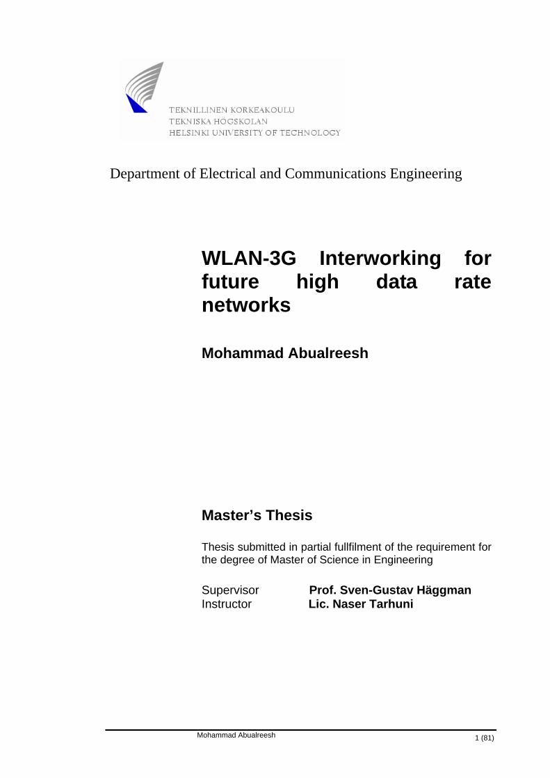
3G network has been evolved through: Release 99, Release 4, Release 5, and Release 6. Figure 2.2 and Figure 2.3 show only the main network elements involved in 3GPP Re-lease 4 and Release 5 network models. Detailed information is provided in [6], [8], and [9].
Mohammad Abualreesh 14 (81)

Master’s Thesis WLAN-3G Interworking for future high data rate networks
The most important difference between GSM/GPRS and 3GPP Release 99 is the em-ployment of a new radio access network based on WCDMA technology. Release 4 al-lows a single control element such as MSC server to control a pool of Media Gateways (MGW’s). In Release 5, IP technology will be supported on larger scale towards All-IP network and the new IP Multimedia Subsystem (IMS) will enable offering new multi-media services.
Figure 2.2 3GPP Release 4 network model, [9]
Figure 2.3 3GPP Release 5 network model, [9]
Mohammad Abualreesh 15 (81)
Master’s Thesis WLAN-3G Interworking for future high data rate networks
2.4 3G Services
From the user point of view the main advantage of UMTS will be a broad offer of ser-vices. Speed, variety and user-friendliness of the services will be significantly improved as compared with GSM [10].
In addition to increasing capacity for more users, 3G services deliver fast and secure wireless connections to the Internet and exciting new data applications for mobile de-vices. These applications and services include position location and mapping, audio and video content, application downloading over the airwaves, multimedia messaging, video conferencing, multi-user games and more [11].
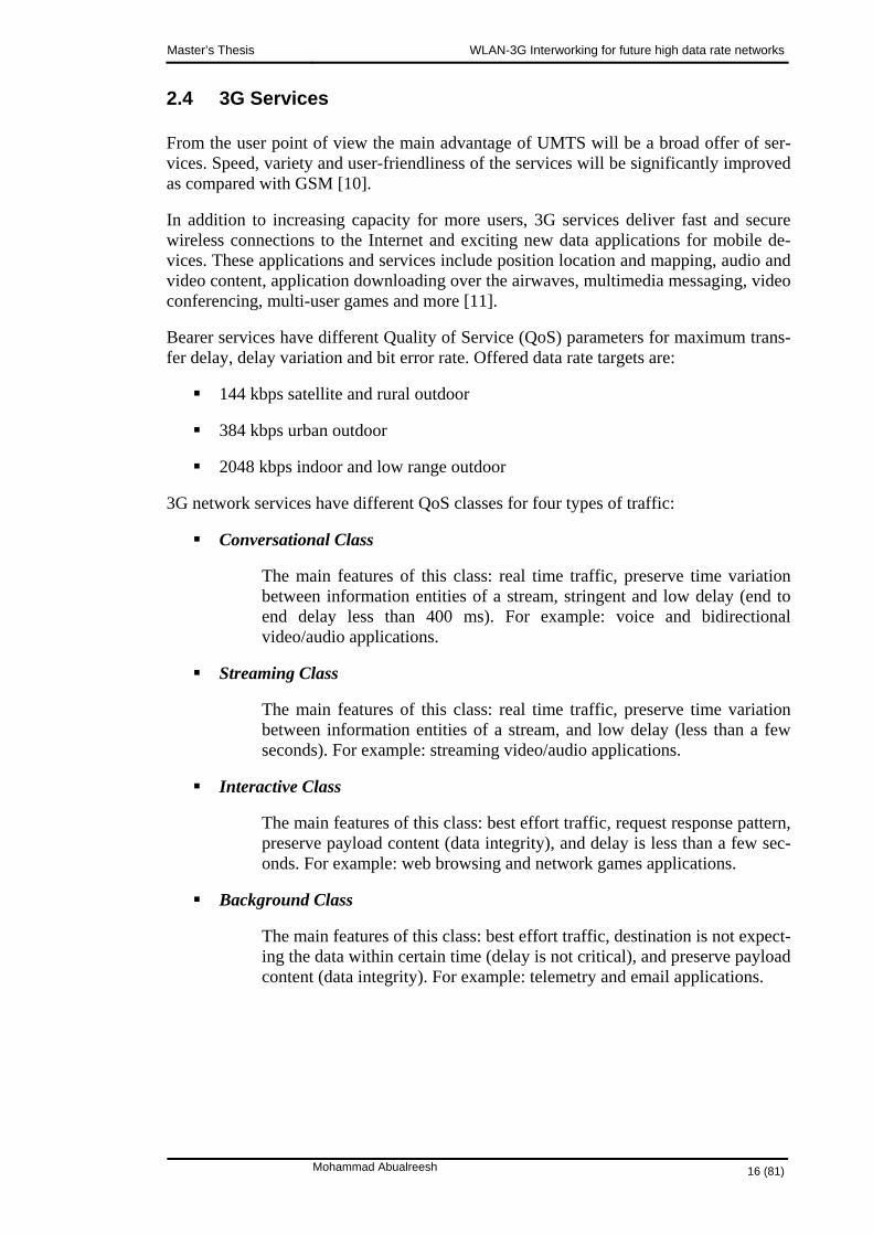
Bearer services have different Quality of Service (QoS) parameters for maximum trans-fer delay, delay variation and bit error rate. Offered data rate targets are:
144 kbps satellite and rural outdoor
384 kbps urban outdoor
2048 kbps indoor and low range outdoor
3G network services have different QoS classes for four types of traffic:
Conversational Class
The main features of this class: real time traffic, preserve time variation between information entities of a stream, stringent and low delay (end to end delay less than 400 ms). For example: voice and bidirectional video/audio applications.
Streaming Class
The main features of this class: real time traffic, preserve time variation between information entities of a stream, and low delay (less than a few seconds). For example: streaming video/audio applications.
Interactive Class
The main features of this class: best effort traffic, request response pattern, preserve payload content (data integrity), and delay is less than a few sec-onds. For example: web browsing and network games applications.
Background Class
The main features of this class: best effort traffic, destination is not expect-ing the data within certain time (delay is not critical), and preserve payload content (data integrity). For example: telemetry and email applications.
Mohammad Abualreesh 16 (81)

Master’s Thesis WLAN-3G Interworking for future high data rate networks
2.5 Summary
This chapter started from one side of the big picture, where the essentials of 3G network were described briefly; the main features, network architecture and services. In the next chapter, the same process will be applied on WLAN telecom network.
Mohammad Abualreesh 17 (81)

Master’s Thesis WLAN-3G Interworking for future high data rate networks
3. WLAN TELECOM NETWORK As there has been a huge development in the mobile telecommunication technologies, there has also been another huge development in WLAN technologies which can not be ignored; especially in the high affordable data rates that exceed those in the mobile technologies. Therefore, this chapter comes to present a brief overview for WLAN technology: main features, principles, standards, and services.
3.1 Background
Everything is going wireless. The prohibitive cost of building wired network infrastruc-tures has paved the way for wireless network technologies on a global scale. The market of wireless communications has grown rapidly since the introduction of IEEE 802.11b WLAN standards, which offer performance more nearly comparable to that of Ethernet. Business organizations value the simplicity and scalability of WLAN’s and the relative ease of integrating wireless access and the ability to roam with their existing network resources such as servers, printers, and internet.
WLAN’s typically augment or replace wired computer networks, providing users with more flexibility and freedom of movement within the workplace. Users can access the company intranet or even World Wide Web (WWW) from anywhere on the company campus without relying on the availability of wired cables and connections.
Various industries have discovered the benefits WLAN which can bring to daily tasks and to the balance sheet. WLAN provides users with more flexibility and freedom of movement within the workplace [12], and [13].
3.2 What is WLAN
In this section, definition, benefits, and standards are previewed briefly.
Mohammad Abualreesh 18 (81)

Master’s Thesis WLAN-3G Interworking for future high data rate networks
3.2.1 WLAN Definition
WLAN is a flexible data communication system, which can be used for applications in which mobility is necessary, in home or indoor business environment. Signals in WLAN are transmitted via radio waves [12]. Thus, WLAN can be identified as a closely grouped system of devices that communicate via radio waves instead of wires.
WLAN supports seamless connectivity, flexibility, mobility, more reliability, lower in-stallation time, installation on difficult to wire area, higher rates, and long term cost sav-ings; which are not available in wired LANs.
3.2.2 WLAN Benefits
Wireless networks offer the following productivity, convenience, and cost benefits over traditional wired networks:
Mobility WLAN allows users real-time access to information from anywhere in their or-ganization, without having to find a place to connect to the network via an Ethernet connection; thereby increasing productivity.
Reliability In WLAN environment, fewer wires and connectors translate to fewer problems for users and network administrators.
Ease and Speed of Installation Installing a wireless system can be fast and easy and can eliminate the need to pull cable through walls and ceilings. Thus, WLAN’s do not require expensive and time-consuming cable installations which form a key particular benefit in difficult - to- wire areas.
Affordability WLAN installation and costs can be significantly lower than those incurred with wired networks; especially in environments that require frequent moves, changes and modifications.
Scalability WLAN systems are easy to configure and rearrange to accommodate a wide va-riety of topology settings and number of users. Configurations can be easily changed and ranged from peer-to-peer networks suitable for a small number of users to large infrastructure networks that enable roaming over a broad area.
Reach of the network WLAN systems can be extended to places which can not be wired.
Flexibility WLAN systems offer more flexibility and adapt easily to changes in the configu-ration of the network.
Reduced cost of ownership
Mohammad Abualreesh 19 (81)

Master’s Thesis WLAN-3G Interworking for future high data rate networks
While the initial investment required for wireless network hardware can be higher than the cost of wired network hardware, overall installation expenses and life-cycle costs can be significantly lower in dynamic environments.
3.2.3 WLAN Standards
IEEE has developed most standards of WLAN, which come as an alphabet soup of IEEE 802.11x series: IEEE 802.11a, IEEE 802.11b, IEEE 802.11g … IEEE 802.11n. In IEEE 802.11x series, all of the definition, features, specifications, and requirements are standardized as will be briefly described here.
The standards of IEEE802.11 proposed different implementations for the physical layer:
Infrared (IR) transmission never implemented
Frequency Hopping Spread Spectrum (FHSS)
Direct Sequence Spread Spectrum (DSSS)
High Rate Direct Sequence Spread Spectrum (HRDSSS)
Orthogonal Frequency Division Multiplexing (OFDM)
IEEE 802.11b provides rates up to 11 Mbps and operates in the 2.4 GHz Industrial, Sci-entific and Medical (ISM) band. However, rates up to 54 Mbps are achieved in IEEE 802.11a which operates in the 5 GHz band and utilizes OFDM technology. Table 3.1 illustrates a brief summary of the main features of the IEEE 802.11x standards.
Table 3.1 Main features WLAN IEEE 802.11 a, b, and g standards, [16]
Standard
IEEE 802.11a
IEEE 802.11b
IEEE 802.11g
Frequency Band • 5 GHz • 2.4 GHz • 2.4 GHz
Data Rate • Up to 54 Mbps
• Up to 11 Mbps
• Up to 54 Mbps
Radio • OFDM • DSSS • OFDM/DSSS
Range • Lower • Higher • Higher
RF Interference Potential
• Good • Lower • Lowest
Interoperability • Not inter-operable with any-one
• Not inter-operable with IEEE 802.11a
• Interoperable with IEEE 802.11b
Multimedia Ap-plication Sup-
port
• Better than IEEE 802.11b
• Lower than IEEE 802.11a
• Lower than IEEE 802.11a
Mohammad Abualreesh 20 (81)

Master’s Thesis WLAN-3G Interworking for future high data rate networks
3.3 WLAN Network Models
WLAN network models and medium access are described here.
3.3.1 WLAN Network Architectures
IEEE 802.11 standards define what comprises Basic Service Set (BSS). BSS has two or more fixed, portable, and/or moving nodes or stations that can communicate with each other over the air in a geographically limited area.
Two configurations are specified in the standards:
Ad hoc mode
Infrastructure mode
The ad-hoc mode is also referred to as the peer-to-peer mode or Independent Basic Ser-vice Set (IBSS) as illustrated in Figure 3.1(a). This ad-hoc mode enables mobile stations to interconnect with each other directly without the use of Access Point (AP). All sta-tions are usually independent and equivalent in the ad-hoc network. Stations may broadcast and flood packets in the wireless coverage area without accessing Internet. The ad-hoc configuration can be deployed easily and promptly when the users involved cannot access or do not need a network infrastructure. For instance, participants of a conference can configure their laptops as a wireless ad-hoc network and exchange data without much effort.
However, as indicated in Figure 3.1 (b), in the infrastructure mode there are AP’s which bridge the mobile stations and the wired network. BSS’s can be connected by a distrib-uted system which normally is LAN. The coverage areas of BSS’s usually overlap. Handover occurs when a station moves from a coverage area of one AP to a coverage area of another AP. Although, the radio range of BSS limits the movement of wireless stations, seamless roaming among BSS’s can construct a campus wide wireless network service [15].
Figure 3.1 WLAN network architectures: (a) Ad hoc mode, and (b) Infrastructure
Mohammad Abualreesh 21 (81)

Master’s Thesis WLAN-3G Interworking for future high data rate networks
3.3.2 Medium Access Method
IEEE 802.11 uses Carrier Sense Multiple Access with Collision Avoidance (CSMA/CA) to access medium. The basic idea of CSMA/CA is: If a station wants to transmit, it first senses the medium. If the medium is busy, the state defers its transmis-sion to a later time. Otherwise, it is allowed to use the medium.
Because of the hidden node problem, collisions could occur. For example, if both sta-tion A and C try to send data to station B at the same time then a collision will occur. To avoid collisions, a Ready To Send /Clear To Send (RTS/CTS) mechanism is imple-mented. When a station gets the chance to send, it sends RTS message first. The desti-nation returns CTS message. After that, the source station can begin to send the data. Since, collisions may not be detected by the source station; the destination will ac-knowledge via ACK message every packet.
3.4 WLAN Services
WLAN’s mainly liberate users from dependence on hard-wired access to the network backbone, giving them anytime, anywhere network access. This freedom to roam offers numerous user services for a variety of work environments, some examples are:
• Easy, real-time network access for on-site consultants or auditors.
• Network managers can move employees, set up temporary offices, or install printers and other equipment without the cost and complexity of wires and ca-bles. Executives can access vital company information from the boardroom through handheld devices equipped with WLAN cards.
• Improved database access for roving supervisors such as production line manag-ers, warehouse auditors, or construction engineers.
• Simplified network configuration for temporary setups such as trade shows or conference rooms.
• Employees can maintain real-time pricing and inventory information.
• Faster access to customer information for service vendors and retailers, resulting in better service and improved customer satisfaction.
• Location-independent access for network administrators, for easier on-site trou-bleshooting and support.
• Real-time access to study group meetings and research links for students.
Mohammad Abualreesh 22 (81)

Master’s Thesis WLAN-3G Interworking for future high data rate networks
• Students and instructors can communicate anywhere on campus. WLAN’s elimi-nate the need for students to visit computer labs or dorm rooms to download as-signments.
• Immediate bedside access to patient information for doctors and hospital staff.
• Hotels and restaurants can process guest reception information, process room service orders, and track guest baggage. Car rental agencies can process car re-turns curbside.
3.5 Summary
This chapter started from the other side of the big picture, where the essentials of WLAN network were described briefly; the main features, network architecture and ser-vices.
From now on, both sides of the big picture will be treated together as what will be seen in the remaining chapters.
Mohammad Abualreesh 23 (81)

Master’s Thesis WLAN-3G Interworking for future high data rate networks
4. 3G FOR WLAN After giving an overview about 3G network and WLAN network; each network being described alone as a completely separated system without relevance to the other system, now it is time to consider and treat both systems being integrated together.
In this chapter, a vision of future high data rate networks will be glanced to reflect the significant importance of changing the ways of thinking about revolution only in mobile technology side alone without considering what has been achieved in WLAN technol-ogy side; especially the huge rates that WLAN offers and they could not be ignored. However, compared to WLAN technology rates, mobile technology rates are still suf-fering from being low.
Based on the huge data rates in WLAN, a new way of thinking has been arisen in which WLAN technology is being involved in the development of 3G technology. This means that WLAN is integrated or interworked with 3G to address some features of the future wireless networks.
The reasons behind this new trend will be explored and discussed here illustratively as what will be seen in this chapter.
4.1 On The Future High Data Rate Wireless Networks Vision
Some ideas and thoughts are discussed in this section; to illustrate the nature of the fu-ture wireless networks for high data rate.
4.1.1 Starting From 3G
In 3G, WCDMA air interface was initially designed to support a wide variety of ser-vices with different QoS requirements having a maximum bit rate of 2 Mbps. In order to satisfy the future service and application needs several technical enhancements have been studied and standardized for WCDMA in 3GPP.
The development of 3G will follow a few key trends, and the evolution following these trends will continue as long as the physical limitations or backward compatibility re-
Mohammad Abualreesh 24 (81)

Master’s Thesis WLAN-3G Interworking for future high data rate networks
quirements do not force the development to move from evolution to revolution. The key trends include:
• Voice services will stay important in foreseeable future, which means that capacity optimization for voice services will continue.
• Together with increasing use of IP-based applications, the importance of data as well as simultaneous voice and data will increase.
• Increased need for data means that the efficiency of data services needs to be im-proved as well as delay and average and peak user data rates.
• When more and more attractive multimedia terminals emerge in the markets, the us-age of such terminals will spread from office, homes, and airports to roads, and fi-nally everywhere. This means that high-quality, high-data-rate applications will be needed everywhere.
• When the volume of data increases, the cost per transmitted bit needs to decrease in order to make new services and applications affordable for everybody.
As a summary for 3G development objectives; the development of 3G will follow a few continuing key trends: increasing capacity optimization for voice services, increasing IP-based applications, supporting simultaneous voice and data improving services effi-ciency, delay, and average and peak user data rates, making more attractive multimedia terminals to be spread out everywhere, achieving high-quality high-data-rate every-where, and finally decreasing cost to be affordable for everybody, [18].
4.1.2 Is 3G Enough
Recently, mobile business professionals have increasingly been looking for an efficient way to access corporate information systems and databases remotely through the Inter-net backbone.
However, the high data rate demands of typical office applications (e.g., large email at-tachment downloading) often calls for very high transmission capacity. Furthermore, certain hot spots like airports and railway stations are natural places to use the services. However, in these places the time available for information download is typically fairly limited.
Wireless telecommunication networks have been developed dramatically. Not only in 3G technology but also in other technologies such as: WLAN, Wireless Personal Area Network (WPAN), Ultra Wide Band (UWB) etc. One question arises here, that is: Is 3G enough? The answer of this question seems to be negative. This is very clear from the huge developments rather than in 3G in which the services and profits exceed what’s gained in 3G. Also, this reinforced from 3G development circle itself which has ex-panded to involve new technologies to cope with increasing wireless users demands. Nowadays, there are talks about 4G and perhaps beyond coming concurrently with 3G which has not been completed and launched effectively yet. Therefore, future wireless networks are being developed beyond 3G.
Mohammad Abualreesh 25 (81)

Master’s Thesis WLAN-3G Interworking for future high data rate networks
One clear side is the data rate trends. The data rate trends are summarized in Figure 4.1 and Figure 4.2 where it is obvious that in evolution path of 3G, very high data rates are achieved in hot spots with WLAN rather than in cellular-based standards.
Figure 4.1 Data Rate Trends [18]
Figure 4.2 Networks vs. Data rate
4.1.3 Addressing WLAN
It is very clear from Section 4.1.2 that the huge amount of data rates that can be achieved through WLAN technologies such as the development of picocell and personal area network technologies (e.g., WLAN and Bluetooth) for office, public, and home in-door solutions.
Mohammad Abualreesh 26 (81)

Master’s Thesis WLAN-3G Interworking for future high data rate networks
Current WLAN products are able to provide data rates up to 54 Mbps. WLAN’s have been mostly used as wireless replacement for wired LAN’s in the office environment.
Together with high-data-rate cellular access, WLAN has the potential to fulfill end user demands in hot spot environments. WLAN offers an interesting possibility for cellular operators to offer additional capacity and higher data rates for end users without sacri-ficing the capacity of cellular users, since WLAN’s operate on unlicensed frequency bands. Furthermore, solutions exist that enable operators to utilize the existing cellular infrastructure investments and well established roaming agreements for WLAN network subscriber management and billing.
4.1.4 Key Objectives
In the light of the above there is a clear need for a public wireless access solution that could cover the increasing demand for data-intensive applications and enable smooth online access to corporate data services in hot spots.
Among future wireless networks is 4G; wherein 4G can be defined as a conceptual framework for or a discussion point to address future needs of a universal high speed wireless network that will interface with wireline backbone network seamlessly. How-ever, 4G can be imagined as an integrated wireless system that enables seamless roam-ing between technologies. A user can be operating in cellular technology network and get handed over to a satellite-based network and back to a fixed wireless network, de-pending upon the network coverage and preference of charging.
In some authors’ opinion [18], before considering some future wireless system as be-longing to 4G, it must possess capabilities that by far exceed those in 3G systems. Judg-ing from an application and services point of view, one distinguishing factor between 3G and 4G will still be the data rate. 4G should support at least 100 Mbps peak data rates in full-mobility wide area coverage and 1 Gbps in low-mobility local area cover-age.
4.1.5 Future Vision
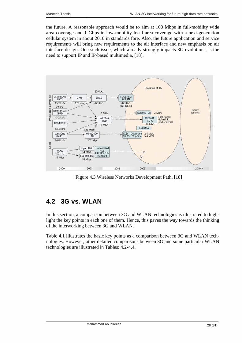
As mentioned earlier, services, applications, and even core network are evolving with high speed, and distinguishing different generations is not really possible anymore. The evolution, and sometimes revolution, is a very significant trend. The other major trend is that access methods will be less tightly coupled to the network. After a certain point, evolution is no longer an answer to air interface development, and revolutionary con-cepts must also be considered. Figure 4.3 illustrates the evolution of 2G/3G cellular and WLAN standards and the revolutionary step toward future wireless systems. GSM evo-lution will continue in parallel with WCDMA. For instance, cdma2000-1X will be fol-lowed by 1XeV-DO (high-bit-rate data only) and 1XeVDV (high-bit-rate data and voice) standards. Looking at development in the Internet and applications, it is clear that the complexity of the transferred content is rapidly increasing and will increase further in the future. Generally, it can be said that the more data rate is available, the more data rate applications will consume. In order to justify the need for a new air interface, tar-gets need to be set high enough to ensure that the system will be able to serve long in
Mohammad Abualreesh 27 (81)
Master’s Thesis WLAN-3G Interworking for future high data rate networks
the future. A reasonable approach would be to aim at 100 Mbps in full-mobility wide area coverage and 1 Gbps in low-mobility local area coverage with a next-generation cellular system in about 2010 in standards fore. Also, the future application and service requirements will bring new requirements to the air interface and new emphasis on air interface design. One such issue, which already strongly impacts 3G evolutions, is the need to support IP and IP-based multimedia, [18].
Figure 4.3 Wireless Networks Development Path, [18]
4.2 3G vs. WLAN
In this section, a comparison between 3G and WLAN technologies is illustrated to high-light the key points in each one of them. Hence, this paves the way towards the thinking of the interworking between 3G and WLAN.
Table 4.1 illustrates the basic key points as a comparison between 3G and WLAN tech-nologies. However, other detailed comparisons between 3G and some particular WLAN technologies are illustrated in Tables: 4.2-4.4.
Mohammad Abualreesh 28 (81)

Master’s Thesis WLAN-3G Interworking for future high data rate networks
Table 4.1 3G vs. WLAN -Key point comparison
Key Point
3G
WLAN
Standards • WCDMA,CDM2000 • IEEE 802.11, other IEEE802. series
Maximum Data Rate • Up to 2 Mbps • 11 Mbps, 54 Mbps … Up to 100 Mbps
Business operators • Mobile phone compa-nies
• Individuels & Wire-less Internet Service Provider (WISP)
Mobility • Higher • Lower
Coverage Area • Several kilometers • Several 100 meters
RF Interference Po-tential
• Lower • Higher
License • Yes • No
Multimedia applica-tion support
• Good • Better
Table 4.2 3G vs. WiFi
Key Point
3G
WLAN
Standards • WCDMA,CDMA2000 • IEEE 802.11
Maximum Data Rate • 2 Mbps • 54Mbps
Mobility • Higher • Lower
Coverage Area • Several kilometers • 100 meters
License • Yes • No
Main Advantages • High Range
• High Mobility
• High Data Rate
• Cheap
Main Disadvantages • Relatively low speed
• Expensive
• Short range
Mohammad Abualreesh 29 (81)
Master’s Thesis WLAN-3G Interworking for future high data rate networks
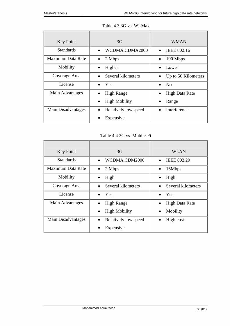
Table 4.3 3G vs. Wi-Max
Key Point
3G
WMAN
Standards • WCDMA,CDMA2000 • IEEE 802.16
Maximum Data Rate • 2 Mbps • 100 Mbps
Mobility • Higher • Lower
Coverage Area • Several kilometers • Up to 50 Kilometers
License • Yes • No
Main Advantages • High Range
• High Mobility
• High Data Rate
• Range
Main Disadvantages • Relatively low speed
• Expensive
• Interference
Table 4.4 3G vs. Mobile-Fi
Key Point
3G
WLAN
Standards • WCDMA,CDM2000 • IEEE 802.20
Maximum Data Rate • 2 Mbps • 16Mbps
Mobility • High • High
Coverage Area • Several kilometers • Several kilometers
License • Yes • Yes
Main Advantages • High Range
• High Mobility
• High Data Rate
• Mobility
Main Disadvantages • Relatively low speed
• Expensive
• High cost
Mohammad Abualreesh 30 (81)

Master’s Thesis WLAN-3G Interworking for future high data rate networks
Hence, from the previous illustrative comparisons mentioned above, it is very clear that the main key advantages of 3G are: the high mobility and high range. While, the high speed is the key advantage of WLAN. Figure 4.4 summarizes those key advantages.
Figure 4.4 Mobility vs. Data Rates for 3G & WLAN
4.3 Thinking Towards The Interworking Between 3G & WLAN
The ongoing standardization of WLAN, research and development activities world-wide, which target bit rates higher than 100 Mbps, combined with the recent successful deployment of WLAN’s in numerous hotspots justify the fact that WLAN technology will play a key role in wireless data transmission. Cellular network operators have rec-ognized this fact, and strive to exploit WLAN technology and integrate this technology into their cellular data networks.
Moreover, when recalling the key points of mobile technologies which offer high mo-bility but with low rates (< 2 Mbps) and that of WLAN technologies which offer high rates (~100 Mbps) but with low mobility. Then, one thing could be highlighted here, that is why the benefits of both technologies are not utilized and combined together to address a new generation of technology that covers the increasing ubiquitous public wireless user demands for high data-intensive applications and enables smooth online access to corporate data services in hot spots.
Therefore, there is currently a strong need for interworking/ integrating mechanisms be-tween WLAN’s and cellular data networks; especially when thinking of the key advan-tages of each one of them being merged and utilized all together as proposed in Figure 4.5.
Mohammad Abualreesh 31 (81)

Master’s Thesis WLAN-3G Interworking for future high data rate networks
Figure 4.4 Proposal of Interworking both 3G and WLAN systems together
4.4 Summary
Different discussion, visions, and comparisons of related issues in 3G and WLAN have been presented in this chapter.
However, after having all the previous discussions, from now on the focus will be on the details of the interworking between 3G and WLAN as will be presented in the next chapters.
Mohammad Abualreesh 32 (81)

Master’s Thesis WLAN-3G Interworking for future high data rate networks
5. WLAN-3G INTERWORKING ARCHITECTURE METHODS
In this chapter, WLAN-3G interworking architecture methods are addressed and dis-cussed in detail. This includes: the definition of the interworking and how it works. It describes the basic features of the different alternatives for WLAN-3G interworking; pointing out their advantages, drawbacks, and their possible impact on WLAN and 3G networks themselves.
According to 3GPP Release 6 [17], the intent of WLAN-3G interworking is to extend 3G services and functionality to WLAN access environment. Thus WLAN effectively becomes a complementary radio access technology to 3G.
WLAN provides access to services located in WLAN’s and/or networks behind WLAN. In WLAN-3G interworking, 3G system functionalities can reside behind WLAN or in parallel to WLAN. In the case of 3G system functionalities located behind WLAN, the interworking between 3G system and WLAN may include:
Enabling usage of 3GPP system functionalities between mobile terminals and 3GPP systems via the WLAN such as providing SIP calls.
Utilising 3G system functionalities to complement the functionalities available in WLAN such as providing charging means, authentication, authorization, and accounting functions.
In a case when the WLAN is seen as a parallel system to 3G system, the interworking between the systems may include:
Creation of mechanisms for selecting and switching between WLAN and 3G systems
Enabling any of these interworking cases mentioned above may result in modifications or additions in 3G systems, in WLAN’s, or in both [17].
Mohammad Abualreesh 33 (81)
Master’s Thesis WLAN-3G Interworking for future high data rate networks
5.1 WLAN-3G Interworking General Overview
5.1.1 Definition
WLAN-3G Interworking is used generally to refer to the interworking between 3G sys-tem and WLAN family of standards. This means combining or integrating both of WLAN and 3G technologies altogether to utilize the benefits of them.
WLAN can provide high data rates capabilities and 3G can provide high mobility capa-bilities. Thus, the new WLAN-3G interworking system will combine both of these key capabilities: high data rate and high mobility together.
WLAN-3G interworking addresses the new generation technology that covers the in-creasing ubiquitous public wireless user demands for high data-intensive applications and enables smooth online access to corporate data services in hot spots.
5.1.2 The Big Picture
Figure 5.1 illustrates a general conceptual view of a WLAN-3G interworking system. The following issues can be noticed:
The end user devices such as laptops, palmtops, and phones that can access networks based on both WLAN and 3G technologies are already becoming available.
A user of this WLAN-3G network would prefer to have exactly one service subscription with one service provider, typically called its home network provider.
The subscribers’ credentials in the form of authentication information (e.g., shared secret keys), the profile information (e.g., class of service, minimum data rate), and the accounting information will be stored in a network-based authentication, authorization, and accounting (AAA) server called home AAA.
This single account will enable the user to access data and voice services anywhere, any time, receive exactly one billing statement, roam freely among all networks with which the user’s provider has agreements, and get similar QoS.
Using a single account on different networks in this way requires that net-work providers be able to authenticate each other’s users and obtain their service profile parameters. This is enabled by roaming agreements estab-lished among service providers using AAA protocols, such as RADIUS or DIAMETER, and AAA broker networks.
Mohammad Abualreesh 34 (81)

Master’s Thesis WLAN-3G Interworking for future high data rate networks
The emerging integrated WLAN-3G wireless networks will offer two roaming services:
Simple IP service that offers integrated billing and subscriber profiles, but does not guarantee session continuity across network boundaries.
Mobile IP service that enables seamless handoffs/ handovers between WLAN-3G networks to preserve ongoing sessions [19].
Figure 5.1 WLAN-3G Interworking: The Big Picture [19]
Mohammad Abualreesh 35 (81)

Master’s Thesis WLAN-3G Interworking for future high data rate networks
5.2 WLAN-3G Interworking Architectural Methods
The main architectural methods which are proposed for integrating WLAN and 3G technologies together are:
The mobile IP architectural method
The gateway architectural method
The emulator architectural method
5.2.1 The Mobile IP Architectural Method
The architectural mobile IP method used to implement WLAN-3G interworking is illus-trated in Figure 5.2. In this method, WLAN and 3G are peer to- peer networks.
Figure 5.2 WLAN-3G Interworking: The Mobile IP Architectural Method, [20]
However, the main characteristics of this method are:
In 3G network, UE uses standard 3G Session Management (3G SM) and GPRS mobility management (GMM) to handle Packet Data Protocol (PDP) sessions and roaming between WCDMA radio access networks.
In WLAN, UE uses IP directly. As for the mobility management in WLAN, mobile IP might be used.
Mobile IP is employed to restructure connections when UE roams from WLAN network to 3G network or vice versa.
Mohammad Abualreesh 36 (81)

Master’s Thesis WLAN-3G Interworking for future high data rate networks
The protocol stack for UE is a dual mode which contains both 3G and WLAN stacks.
The handover from 3G network to WLAN network is done by disabling UE 3G stack and using IP stack.
The same IP can be maintained in case of WLAN-3G handover so this gives a kind of continuous session connectivity.
Foreign Agent (FA) and Home Agent (HA) are installed in Access Router (AR) in WLAN and in GGSN in 3G so that FA/HA can help routers to tun-nel and forward the data packets.
Outside its home network, UE is identified by Care Of Address (COA) asso-ciated with its point of attachment a co-located FA that manages de-encapsulation and delivery of packets.
UE registers its COA with HA which resides in UE’s home network and is responsible for intercepting datagrams addressed to the UE’s home address as well as encapsulating them to the associated COA.
The datagrams to UE is always routed through HA, while the datagrams from UE are relayed along an optimal path by the Internet routing system, though which it is possible to employ reverse tunneling through HA.
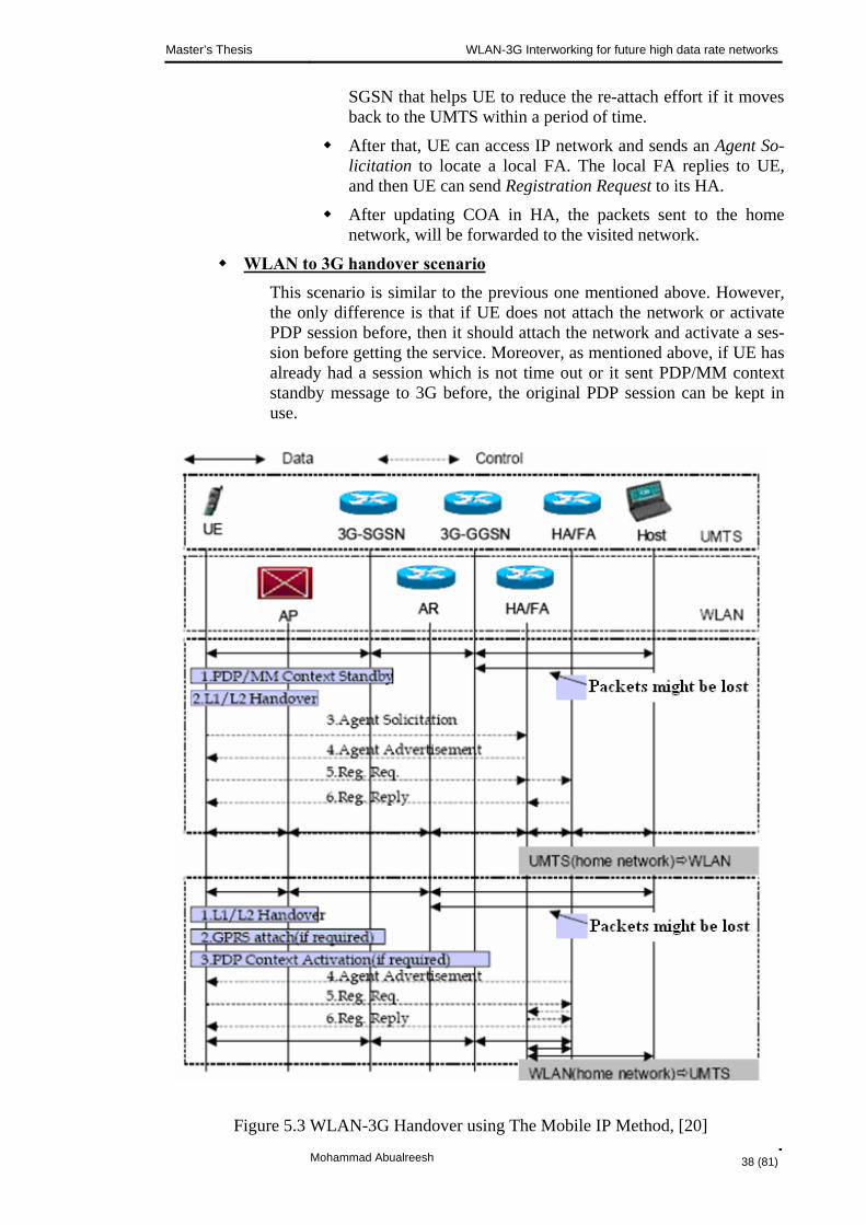
5.2.1.1 Handover WLAN-3G handover procedure using the mobile IP method is illustrated in Figure 5.3. The figure shows two different handover scenarios. The upper part of the figure is 3G to WLAN handover and the lower part of the figure is WLAN to 3G handover. The two handover scenarios are described as follows:
3G to WLAN handover scenario
Let us assume that 3G is the home network forUE so the handover pro-cedure is as follows.
Initially, UE is sending or receiving data packets from 3G network.
Once UE decides or the network decides to handover to WLAN, it starts with a set of Layer1/Layer2 (L1/L2) hand-over procedures.
The UE might move to WLAN for a period of time, and moves back to the original UMTS later.
To prevent UMTS detaches UE because that UMTS does not receive the periodical Router Area (RA) update message from UE, UE can send PDP/MM context standby message to its
Mohammad Abualreesh 37 (81)
Master’s Thesis WLAN-3G Interworking for future high data rate networks
SGSN that helps UE to reduce the re-attach effort if it moves back to the UMTS within a period of time.
After that, UE can access IP network and sends an Agent So-licitation to locate a local FA. The local FA replies to UE, and then UE can send Registration Request to its HA.
After updating COA in HA, the packets sent to the home network, will be forwarded to the visited network.
WLAN to 3G handover scenario This scenario is similar to the previous one mentioned above. However, the only difference is that if UE does not attach the network or activate PDP session before, then it should attach the network and activate a ses-sion before getting the service. Moreover, as mentioned above, if UE has already had a session which is not time out or it sent PDP/MM context standby message to 3G before, the original PDP session can be kept in use.
Figure 5.3 WLAN-3G Handover using The Mobile IP Method, [20]
Mohammad Abualreesh 38 (81)

Master’s Thesis WLAN-3G Interworking for future high data rate networks
5.2.1.2 Pros & Cons The advantage of this mobile IP architectural method is that it is based on the mobile IP which makes IP address mobile. The same IP is used which solves the multiple address problem and gives a kind of continuous session connectivity.
To solve the packet duplication due to the lifetime of the routers, some conventions on both WLAN and 3G networks are needed. The databases of both networks may need to communicate to overcome the packet duplication issue.
The disadvantage of mobile IPv4 is the triangle routing. This could be overcome in the mobile IP when using the optimized routing. This is so important for real-time applica-tions such as audio or video transmission.
In general, the existing mobile IP, WLAN and 3G standards are quite enough and ma-ture to support the mobile IP method. However, the handover latency and the packet loss are its two major problems.
5.2.2 The Gateway Architectural Method
The architectural gateway method used to implement WLAN-3G interworking is illus-trated in Figure 5.4. Also, in this method, WLAN and 3G are peer to- peer networks.
Figure 5.4 WLAN-3G Interworking: The Gateway Architectural Method, [20]
Mohammad Abualreesh 39 (81)

Master’s Thesis WLAN-3G Interworking for future high data rate networks
However, the main characteristics of this method are:
A gateway is used to interconnect WLAN and 3G networks together.
The gateway is an intermediate server (mobile proxy) that is implemented between WLAN and 3G and handles mobility and routing.
Here, UE uses standard SM and GMM to access the 3G network and uses the standard IP to connect to the WLAN network.
In WLAN, UE may use mobile IP to handle the mobility within WLAN but this is not necessary.
For users having interworking services, the control signals and data packets are routed through the gateway.
The gateway method aims to separate the operations of the two networks and enables the intersystem roaming of the two networks.
The merits of this method are that the two networks can be operated inde-pendently and the mobile IP is not necessary.
5.2.2.1 Handover WLAN-3G handover procedure using the gateway method is illustrated in Figure 5.5. The figure shows two different handover scenarios. The upper part of the figure is 3G to WLAN handover and the lower part of the figure is WLAN to 3G handover. The two handover scenarios are described as follows:
3G to WLAN handover scenario Let us assume that 3G is the home network for UE so the handover pro-cedure is as follows.
Initially, UE is sending or receiving data packets from 3G network.
Once UE decides or the network decides to handover to a WLAN, it starts with a set of L1/L2 handover procedures.
Then, UE tries to obtain a gateway address, for example using Dynamic Host Connection Protocol (DHCP), in order to per-form the intersystem handover procedures.
UE sends a DHCPDISCOVER to ask a gateway address in the visited network and gateway replies UE with its IP address.
After UE obtains the gateway address, it sends RA update to the gateway using its original IP address of the 3G network.
Mohammad Abualreesh 40 (81)

Master’s Thesis WLAN-3G Interworking for future high data rate networks
Then, the gateway sends a standard Update PDP Contexts Request to GGSN to ask GGSN to change its SGSN address-in-use.
Once a GGSN receives a PDP context request from a gate-way, it knows that UE moves to WLAN environment.
The gateway becomes SGSN temporally; so packets to UE should go to the gateway instead of the old SGSN.
As described in mobile IP method, since UE might moves back to 3G network, it is better not to delete UE’s MM and PDP context for the performance issue.
After the whole roaming procedures, UE sends the packets out using its original IP address of 3G network.
Figure 5.5 WLAN-3G Handover using The Gateway Method, [20]
Mohammad Abualreesh 41 (81)

Master’s Thesis WLAN-3G Interworking for future high data rate networks
The packets from UE to Internet can be sent through WLAN network if WLAN does not perform ingress filtering on the 3G IP address. If WLAN applies the ingress filtering on non-WLAN IP addresses, then packets should go to the gateway and then to Internet. However, for these packets back to UE, should go to 3G network based on IP routing.
GGSN recognizes that UE moves to WLAN and it tunnels the packets to the gateway.
WLAN to 3G handover scenario Let us assume that 3G is the home network for UE due to the fact that UE can access 3G radio access network only if UE is the subscriber of 3G network. Hence, the handover procedure is as follows.
Initially, UE is sending or receiving data packets from WLAN network.
Once UE decides or the network decides to handover to 3G network, it performs 3G standard procedures.
If UE has already attached to 3G network and in the same RA, it can just start the service.
If it is the first time to attach UE to the network, it should per-form attach and PDP context activation and then it can start the service.
In the attach procedures, UE uses the gateway as its Access Point Name (APN) to inform SGSN that it wants to use WLAN IP.
During PDP context activation procedure, UE uses WLAN IP to request PDP context.
Once the gateway detects the IP is WLAN IP and the security process is passed, it responses UE with the same WLAN IP.
UE can use the same IP address that was used in WLAN.
Here, the gateway simulates GGSN in 3G network.
SGSN sends outgoing packets to the gateway and incoming packets go through the gateway to SGSN.
Both incoming and out-going packets go through the same path.
Internet hosts sending packets to WLAN UE, first go to the WLAN network, then received by the gateway, and then sent to SGSN and finally ended to UE.
Mohammad Abualreesh 42 (81)

Master’s Thesis WLAN-3G Interworking for future high data rate networks
5.2.2.2 Pros & Cons The key merits of this gateway architectural method are that: Firstly, handover is faster and packet loss is less than in the mobile IP method since all signaling messages are routed within the internal network. Secondly, the mobile IP is not required so this leads to minimizing the encapsulation and routing inefficiencies with the mobile IP. Thirdly, the two 3G and WLAN networks can still handle their single mode users independently. Also, gateways (or proxies) are already in place in many organizations as firewalls or web servers. Theses gateways may be reused and utilized further for mobility manage-ment and inter-technology roaming.
However, Internet and 3G standards are not enough to support this gateway method. Some 3G protocols should be refined for additional controls and the exchange of AAA and HLR information should be further defined. Yet, this gateway method is not stan-dardized. Obviously, in case of deploying a single gateway and it fails then it may lead to failure of the entire network so there is a need to have some fault tolerance and better gateway deployment.
5.2.3 The Emulator Architectural Method
The architectural emulator method used to implement WLAN-3G interworking is illus-trated in Figure 5.6. Also, in this method, WLAN and 3G are peer to- peer networks.
Figure 5.6 WLAN-3G Interworking: The Emulator Architectural Method, [20]
Mohammad Abualreesh 43 (81)

Master’s Thesis WLAN-3G Interworking for future high data rate networks
However, the main characteristics of this method are:
WLAN AP is connected to the 3G network through 3G-SGSN.
In this method, WLAN is treated as a routing area associated with 3G-SGSN; thus WLAN looks like RNC to 3G network.
UE, whether connected to the 3G network or the WLAN, is always treated as a 3G user.
The inter-system roaming arises only when UE is connected to WLAN net-work.
A dual WLAN/3G mode UE is required to access both networks.
The session management and the mobility management are handled by 3G SM and GMM.
UE cannot access Internet through WLAN directly.
This method tightly couples the two networks and WLAN can be viewed as a slave network of 3G. Due to this fact, this method is also called tightly coupled method.
Here, every packet should pass through GGSN, which becomes the bottle-neck.
Running IP-sessions are not interrupted because the IP address of UE termi-nal is not changed.
When UE leaves WLAN coverage area the service quality degrades; espe-cially for those sessions which use WLAN high throughput capabilities.
The key benefit of this method is that the handover delay is much lower than the two mobile IP method and gateway method.
5.2.3.1 Handover In this emulator method, WLAN-3G handover procedure is quite similar to 3G RNC handover. WLAN coverage area is treated as one routing are for CN. If UE enters or leaves a routing area, an update message is sent to CN of the 3G network; hence 3G-SGSN can simply distinguish RAN via routing areas.
However, this could be illustrated by an example as shown in Figure 5.7. From this fig-ure the following can be noticed:
Mohammad Abualreesh 44 (81)

Master’s Thesis WLAN-3G Interworking for future high data rate networks
When WLAN AP acts as an RNC then the handover procedures are equiva-lent to the serving RNC relocation between two WCDMA RNC’s.
The Radio Resource Management (RRM) and Radio Resource Control (RRC) of WLAN are different from WCDMA RRC and RRM.
The parameters such as the radio link context carried in the Relocation Re-quest message are translated into WLAN radio resource control method.
Figure 5.7 WLAN-3G Handover using The Emulator Method, [20]
Mohammad Abualreesh 45 (81)

Master’s Thesis WLAN-3G Interworking for future high data rate networks
5.2.3.2 Pros & Cons As an advantage of this emulator method, mobility management, roaming, billing, and location related issues are taken care by 3G network. Moreover, this method provides a kind of compatibility integration of WLAN with GSM/GPRS/UMTS networks where WLAN UE credentials and security levels are of identical format to GSM/GPRS/UMTS. The strong security provided in 3G and QoS for real time services may now be provided over WLAN as well; thus resolving the drawbacks of the current IEEE 802.11a/b/g WLAN threats.
However, the key benefit of the emulator method is that the handover delay is much lower than the mobile IP method and the gateway method.
On the other hand, every packet should pass through GGSN, which becomes the bottle-neck. Also, WLAN high data rates such as 11 Mbps/ 54 Mbps would be degraded to the rates of the 3G terminal (2 Mbps). In this method, a WLAN standard terminal needs to be modified which in turn would make them more expensive. Thus, the two attractive WLAN feature (speed and price) would be lost in this method.
Although, the emulator method achieves high efficiency, to use WLAN as 3G access stratum, it is not yet standardized. Basically, this emulator method and the other two mobile IP and gateway methods are not yet standardized and still under study.
5.2.4 Other Possible Architectural Methods
There are other proposed possible architectural methods used to integrate WLAN and 3G networks together. In this section we briefly present them.
As an alternative for the third emulator method, in which WLAN is interconnected to 3G through 3G-SGSN i.e. emulating RNC, another possible kind of emulator can be used to interconnect WLAN and 3G network through GGSN i.e. emulating 3G-SGSN. This is called 3G-SGSN emulator. However, the advantage of this method is that some overhead caused by available but not needed functionality is avoided compared with RNC emulator. If the 3G-SGSN emulator does the adaptation between WLAN and 3G packet formats, then GGSN can remain unaltered. On the other hand, GGSN might be-come a problem if its capacity is not designed to fulfil the growth of the traffic. If the adaptation is done by GGSN, taking into account the increased need for the data rate, the speed of WLAN can be utilized in full.
Another possibility to integrate WLAN and 3G together is to use Virtual Access Point (VAP) to interconnect both networks together. Unlike the emulator approach, here WLAN is the master network and 3G is the slave. The mobility is managed according to IEEE802.11 WLAN standard. From WLAN point of view, the entire 3G network ap-pears as a basic service set associated with another access point (VAP in this case). The function of the VAP is to communicate with UE’s connected through 3G, de-encapsulate their packets, and transmit them on the corporate WLAN. After this is done, the packets will reach the final destination through the router attached to the corporate WLAN. However, this VAP method does not have significant advantages over the pre-vious methods. It is not clear how VAP will operate with normal WLAN AP’s. The overhead of packets in this method is quite large, which makes the method inefficient.
Mohammad Abualreesh 46 (81)

Master’s Thesis WLAN-3G Interworking for future high data rate networks
5.3 Summary
WLAN-3G interworking big picture and its architecture methods have been illustrated in this chapter. With the highlight of: how the interworking works, the basic features of the different alternatives for WLAN-3G interworking; pointing out their advantages and drawbacks.
In the next chapter, case studies are addressed: some results of the current researches and some simulations were developed in this thesis; in order to evaluate some of the in-terworking methods that were presented in this chapter.
Mohammad Abualreesh 47 (81)

Master’s Thesis WLAN-3G Interworking for future high data rate networks
6. SIMULATION & EVALUATION After having WLAN-3G interworking related issues explained, here some simulation will be demonstrated to evaluate certain aspects of WLAN-3G interworking.
As mentioned in chapter 5, the main methods used to implement WLAN-3G interwork-ing are: the mobile IP methods, the emulator method, and the gateway method. Each one of these methods enjoys some pros and suffers from some cons. Here, case studies are addressed: based on results of the current researches and some simulations devel-oped in this thesis; in order to evaluate some aspects of the interworking methods which were presented in chapter 5.
Basically, in this chapter, the main methods used to implement WLAN-3G interworking will be evaluated from the handover delay point of view. It will be seen how each method behaves in the case of handover and how long the user waits in case of hand-over between WLAN-3G service areas. All of these methods will be compared as well.
6.1 QoS of Wireless Networks
This will be an introduction to the evaluation metrics which used for evaluating 3G-WLAN interworking methods as will be seen later in this chapter.
Wireless networks differ from wired networks in the access technologies and the char-acteristics of the transmission medium. In this section some important characteristics of the wireless medium – which affect QoS of wireless networks- will be pointed out, [22].
6.1.1 Wireless Topology
The wireless network consists of wireless access points called Base Station (BS) in 3G or AP in WLAN, where each access point covers a certain geographical area. Frequency reuse is used in some wireless technologies such as GSM. However, in WCDMA, the frequency reuse factor equals to one.
Mohammad Abualreesh 48 (81)

Master’s Thesis WLAN-3G Interworking for future high data rate networks
6.1.2 Mobility
User mobility and wireless topology are the reasons why handover is necessary. More-over, a wireless mobile user frequently changes its location; thus resulting in time vary-ing bit error ratio and interference, which directly defines the QoS of the wireless net-work.
Handover schemes have what so called handover latency or handover delay. This is the time period during which the wireless mobile user is unable to send or receive IP pack-ets or calls. In certain scenarios such as mobile IP – as will be seen later in this chapter the handover delay may be greater than what is acceptable for real time services.
Also, handover may cause packet losses or call dropping. Such losses may disrupt both real time and non real time services, and hence are undesirable.
User mobility introduces another problem: location control. It is necessary to track the wireless mobile users within the wireless network. Certain location management schemes are used in wireless networks for keeping track of wireless mobile users.
6.1.3 Bit Error Rate
Bit error in wireless links may occur due to different causes such as: interference, inter-ference noise, multipath fading, and shadowing.
Fading or path loss is one of the main characteristics of signal propagation over a wire-less link. One general formula for path loss is given in the following equation:
αdfc
PPL
T
R2
1== (6.1)
Where :
RP : is the received power at the receiver (the wireless access point or the wireless mo-bile user)
TP : is the transmitted power at the transmitter (the wireless access point or the wireless mobile user)
f : is the frequency
d : is the distance between the transmitter and the receiver
α :is a factor depends upon the characteristics of the wireless medium usually indicated as the path loss exponent. Typical values between 3 and 5.
c : is a constant
Shadowing is a result of obstacles on the path of the radio waves (i.e. there is no line of sight between the wireless access point and the wireless mobile user). Furthermore, due to the reflection of the signal from surrounding objects such as buildings, different parts of the same signal may arrive to the receiver via different paths. This leads to what is
Mohammad Abualreesh 49 (81)
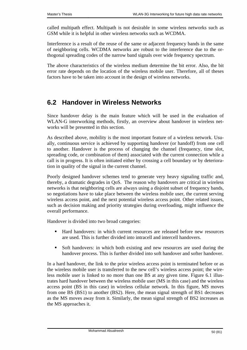
Master’s Thesis WLAN-3G Interworking for future high data rate networks
called multipath effect. Multipath is not desirable in some wireless networks such as GSM while it is helpful in other wireless networks such as WCDMA.
Interference is a result of the reuse of the same or adjacent frequency bands in the same of neighboring cells. WCDMA networks are robust to the interference due to the or-thogonal spreading codes of the narrow band signals over wide frequency spectrum.
The above characteristics of the wireless medium determine the bit error. Also, the bit error rate depends on the location of the wireless mobile user. Therefore, all of theses factors have to be taken into account in the design of wireless networks.
6.2 Handover in Wireless Networks
Since handover delay is the main feature which will be used in the evaluation of WLAN-G interworking methods, firstly, an overview about handover in wireless net-works will be presented in this section.
As described above, mobility is the most important feature of a wireless network. Usu-ally, continuous service is achieved by supporting handover (or handoff) from one cell to another. Handover is the process of changing the channel (frequency, time slot, spreading code, or combination of them) associated with the current connection while a call is in progress. It is often initiated either by crossing a cell boundary or by deteriora-tion in quality of the signal in the current channel.
Poorly designed handover schemes tend to generate very heavy signaling traffic and, thereby, a dramatic degrades in QoS. The reason why handovers are critical in wireless networks is that neighboring cells are always using a disjoint subset of frequency bands, so negotiations have to take place between the wireless mobile user, the current serving wireless access point, and the next potential wireless access point. Other related issues, such as decision making and priority strategies during overloading, might influence the overall performance.
Handover is divided into two broad categories:
Hard handovers: in which current resources are released before new resources are used. This is further divided into intracell and intercell handovers.
Soft handovers: in which both existing and new resources are used during the handover process. This is further divided into soft handover and softer handover.
In a hard handover, the link to the prior wireless access point is terminated before or as the wireless mobile user is transferred to the new cell’s wireless access point; the wire-less mobile user is linked to no more than one BS at any given time. Figure 6.1 illus-trates hard handover between the wireless mobile user (MS in this case) and the wireless access point (BS in this case) in wireless cellular network. In this figure, MS moves from one BS (BS1) to another (BS2). Here, the mean signal strength of BS1 decreases as the MS moves away from it. Similarly, the mean signal strength of BS2 increases as the MS approaches it.
Mohammad Abualreesh 50 (81)

Master’s Thesis WLAN-3G Interworking for future high data rate networks
Figure 6.1 Hard handover in wireless cellular network
A hard handover occurs when the old connection is broken before a new connection is activated. The performance evaluation of a hard handover is based on various initiation criteria such as:
Relative signal strength: in this method the strongest received wireless access point (BS) is selected at all times. The decision is based on measurement of the mean of the received signal. This method is observed to provoke too many un-necessary handovers, even when the signal of the current wireless access point is still at an acceptable level.
Relative signal strength with threshold: This method allows a wireless mobile user (MS) to handover only if the current signal is sufficiently weak (less than certain threshold) and the other is the stronger of the two.
Basically, in this chapter, the hard handover is considered. The relative signal strength with threshold will be used as handover initiation criteria.
Reference to the handover in UMTS-WLAN interworking system, there are two hand-over scenarios as illustrated in Figure 6.2:
BS to AP scenario: the wireless mobile user (MS) moves from UMTS area to-wards WLAN area leaving its previous serving wireless access point (BS) and approaching the new hosting wireless access point (AP).
AP to BS scenario: the wireless mobile user (MS) moves from WLAN area to-wards UMTS area leaving its previous serving wireless access point (AP) and approaching the new hosting wireless access point (BS).
These handover scenarios will be used in evaluating 3G-WLAN interworking methods.
Mohammad Abualreesh 51 (81)
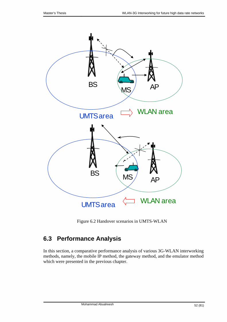
Master’s Thesis WLAN-3G Interworking for future high data rate networks
APBS
6.3 Performance Analysis
In this section, a comparative performance analysis of various 3G-WLAN interworking methods, namely, the mobile IP method, the gateway method, and the emulator method which were presented in the previous chapter.
WLAN areaUMTS area
APBS
WLAN area
MS
MS
UMTS area
Figure 6.2 Handover scenarios in UMTS-WLAN
Mohammad Abualreesh 52 (81)

Master’s Thesis WLAN-3G Interworking for future high data rate networks
6.3.1 Performance Metrics
There are several performance metrics that can be used to quantify the performance provided by a particular WLAN-3G interworking method. However, the following main performance metric will be used in evaluation the performance of such interworking methods:
Handover delay: is the time between the initialization and the end of the hand-over between BS and AP. It is the time the wireless mobile user (MS) needs to wait until the handover process is completed among BS-AP. The handover de-lay, can be formulated as: hD
wth DDD += (6.2)
Where:
tD : is the time spent in transmission between MS and AP/BS
wD : is the waiting time spent in handover processing in the network
In addition to handover delay performance metric, another parameter will used in the evaluation process such as: number of handovers between WLAN- UMTS networks, number of dropped calls between WLAN-UMTS networks.
6.3.2 Handover Delay in the Interworking Methods
As described in the previous chapter, various methods are used to implement WLAN-3G interworking. Each method has its own architecture and applies its own handover procedure. Mainly, the handover delay issue will be explained for the mobile IP method, the gateway method, and the emulator method and also these methods will be evaluated based on such performance metric.
The handover delay consists of two parts: the delay due to transmission and the waiting delay due to handover processing. The handover delay part due to transmission is com-mon to all interworking methods since it depends only on the distance between MS and AP/BS; thus it can be eliminated from the comparison of the interworking methods.
However, the waiting delay due to handover processing is dependent on the network itself and the various involved components. Therefore, this part can not be eliminated from the comparison of the interworking methods. It represents the key part of the hand-over delay.
The handover delay differs from one interworking method to another. In the mobile IP method, see Figure 5.3, the various components of the waiting delay can be deduced as follows:
In case of UMTS to WLAN handover, the waiting delay, is the sum of: wD
1D : the time spent in PDP/MM context standby and L1/L2 handover data among UE, 3G-SGSN, 3G-GGSN, and host.
Mohammad Abualreesh 53 (81)

Master’s Thesis WLAN-3G Interworking for future high data rate networks
2D : the time spent in agent solicitation, advertisement, and registration controls among UE, WLAN HA/FA and UMTS HA/FA.
In case of WLAN to UMTS handover, the waiting delay, is the sum of: wD
1'D : the time spent in GPRS attach, PDP/MM context activation, and L1/L2
handover data among UE, AP, AR, and host.
2'D : the time spent in agent advertisement, and registration controls among
UE, WLAN HA/FA and UMTS HA/FA.
In the gateway method, see Figure 5.5, the various components of the waiting delay can be deduced as follows:
In case of UMTS to WLAN handover, the waiting delay, is the sum of: wD
3D : the time spent in L1/L2 handover data among UE, 3G-SGSN, 3G-GGSN, and host.
4D : the time spent in DHCP setup, RA update and PDP context controls among UE, Gateway, 3G-SGSN, and 3G-GGSN.
In case of WLAN to UMTS handover, the waiting delay, equals: wD
3'D : the time spent in GPRS attach, PDP/MM context activation, and L1/L2
handover data among UE, AP, AR, host, and 3G-GGSN.
In the gateway method, see Figure 5.7, the components of the waiting delay can be de-duced as follows:
In case of UMTS to WLAN handover or WLAN to UMTS handover, the wait-ing delay, equals: wD
5D : the time spent in L1/L2 handover data among UE, 3G-SGSN, 3G-GGSN, and host.
The previous analysis is summarized in the following relation:
⎪⎪⎪
⎩
⎪⎪⎪
⎨
⎧
→→→
→+→+
→+
=
emulatorumtswlanwlanumtsDgatewayumtswlanD
gatewaywlanumtsDDmobileIPumtswlanDD
mobileIPwlanumtsDD
Dw
:/.....,.........:.............................,.........
:.....................,.........:....................,.........
:......................,.........
5
3'
43
2'
1'
21
(6.3)
As a rough estimate comparison, the handover processing components can be used to give a general indication about the interworking methods assuming all components have the same conditions.
Mohammad Abualreesh 54 (81)

Master’s Thesis WLAN-3G Interworking for future high data rate networks
For the mobile IP method and the gateway method, is greater than since they access the same components but involves more data to be processed. is greater than since in the processing occurs in the same UMTS network while it involves both WLAN network and UMTS network in . Moreover, is approximately simi-lar to . Thus, the waiting delay in the mobile IP method is greater than that in the gateway method.
1D 3D
1D 2D
4D 2D
4D 1'D
3'D
For the emulator method, the waiting delay involves only one item which is processed in the same network since WLAN is considered as one cell of UMTS network so the handover is performed as it is within the UMTS network. Thus, it is expected that the emulator method has lower waiting delay than the mobile IP method and the gateway method.
As an expected summary, the emulator method has the lowest handover delay among the three interworking methods, and then comes the gateway method and then lastly the mobile IP method.
6.3.3 Performance Observations
This section demonstrates some performance studies of the three interworking methods. This is based on some publications found to have a relation with this topic [20], and [23].
Although those publications are concerned with interworking methods in different simu-lation network architectures and traffic models than what used here, some results can be safely generalized to the system model used here.
Furthermore, these performance studies will be used to validate the system model and to prove or confirm the deduced results and the drawn conclusions.
As illustrated in those publications [20], and [23], the performance studies are based on simulations. One simulation which will be described here will be used to confirm de-duced results and the drawn conclusion.
The simulation environment for this simulation has a UMTS network and a WLAN net-work implemented using NS2, which developed by UC Berkeley. The simulation pa-rameters are following:
UMTS network has a 100 Mbps backbone with 5 radio network subsystems and offers 32 kbps data services.
WLAN has 25 AP’s and provides 100 kbps data service.
It is assumed that 50 % of the users are WLAN users and the other 50 % of the users are UMTS users.
Among all users, 50 % are dual mode users and might move in between two net-works, and the other 50 % are single mode users using either WLAN or UMTS.
Mohammad Abualreesh 55 (81)
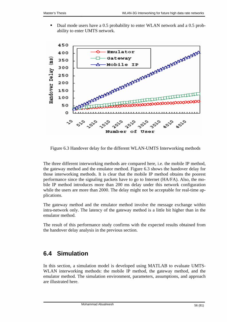
Master’s Thesis WLAN-3G Interworking for future high data rate networks
Dual mode users have a 0.5 probability to enter WLAN network and a 0.5 prob-ability to enter UMTS network.
Figure 6.3 Handover delay for the different WLAN-UMTS Interworking methods
The three different interworking methods are compared here, i.e. the mobile IP method, the gateway method and the emulator method. Figure 6.3 shows the handover delay for those interworking methods. It is clear that the mobile IP method obtains the poorest performance since the signaling packets have to go to Internet (HA/FA). Also, the mo-bile IP method introduces more than 200 ms delay under this network configuration while the users are more than 2000. The delay might not be acceptable for real-time ap-plications.
The gateway method and the emulator method involve the message exchange within intra-network only. The latency of the gateway method is a little bit higher than in the emulator method.
The result of this performance study confirms with the expected results obtained from the handover delay analysis in the previous section.
6.4 Simulation
In this section, a simulation model is developed using MATLAB to evaluate UMTS-WLAN interworking methods: the mobile IP method, the gateway method, and the emulator method. The simulation environment, parameters, assumptions, and approach are illustrated here.
Mohammad Abualreesh 56 (81)

Master’s Thesis WLAN-3G Interworking for future high data rate networks
6.4.1 System Model
The system model used in the simulation consists of a UMTS network and a WLAN being interworked using the three interworking methods.
Each network has a single wireless access point, i.e. UMTS has a single BS and WLAN has a single AP. The coverage area of each wireless access point is a circle with radius R and the wireless access point is located at the center of the coverage area. It is not necessary that both coverage areas are equal. Figure 6.4 shows the coverage areas for BS and AP.
APBS
MS
WLAN areaUMTS area
Figure 6.4 System model
Each network has its own users which are uniformly distributed among the coverage area. The wireless mobile users (MS) can move freely between both networks.
The position of a MS is defined with r and φ coordinates (indirectly x,y coordinates), where r is the distance from the center of the area and φ is the angle with the horizon-tal axis . The power distribution function (pdf) for the user density in the area is given by:
( )⎩⎨⎧
>≤≤
=................,.........0
0,........./2 2
RrRrRr
rfr (6.4)
Also, the pdf for φ is given by:
( ) πφπφφ 20...,.........2/1 ≤≤=f (6.5)
In this model, the movement direction and the magnitude of the velocity, of the users are assumed to remain constant within one simulation time step; these are allowed to change at handover to the other area. The pdf for
v
θ is given by:
Mohammad Abualreesh 57 (81)
Master’s Thesis WLAN-3G Interworking for future high data rate networks
( ) πθπθθ 20...,.........2/1 ≤≤=f (6.6)
The pdf for the velocity is given by:
( )( )
⎪⎩
⎪⎨
⎧
<
≥=
−−
0........................,.........0
0,........21 2
2
2
v
vekvf
mv
v
ο
οπ (6.6)
m is the average velocity of the user
ο is the standard deviation
∫ −+=
ο
π2
0
2121
1m
x dxek is constant
Thus, in this system model the following assumptions are made:
The users are uniformly distributed within each area.
The initial location of each user is defined by r and φ coordinates (indirectly x,y coordinates).
The angles of the direction of movement, θ , are uniformly distributed.
The users are allowed to move in any direction from the starting location.
The velocity of each user is constant during the simulation time step.
The users can freely move among both areas.
Calls from different users are independent.
6.4.2 Simulation Approach
The simulation is based on a program code developed in MATLAB. It runs for a certain number of iterations as specified by the simulation parameters which are set at the be-ginning of the simulation. Figure 6.5 summarizes the simulation approach.
Mohammad Abualreesh 58 (81)

Master’s Thesis WLAN-3G Interworking for future high data rate networks
Figure 6.5 Simulation approach
Initialize users’ location
Set simulation parameters
Power claculations
Power< Threshold?
Handover delay evaluation
Is the user at
cell border?
Set users’ velocitiesUpdtate their locations
Is simultion
time ended?
Handover the user to other area
Drop user
Yes Yes
Yes
No
No
No
Start
End
Draw results
First, the simulation parameters are set; so the simulation will run according to the specified simulation time and each iteration lasts according to the specified time step. The number of iterations equals to the simulation time divided by the time step.
In every iteration, the mobility of user is set by setting their velocities’ magnitude and their direction of movements. Based on that, the users’ locations are updated. Hence, the power of the signal is calculated for each user and compared to a certain predefined threshold. If the power of the signal is less than the predefined threshold; then this means the user should handover to the other area. However, the handover occurs if the power of the signal is less than the predefined threshold and if the user moves towards the next area (in the simulation this is done when the user is at the area border or the direction of movement, θ is within 2/0 πθ ≤≤ , or πθπ 22/3 ≤≤ ).
In the same iteration, the handover delay for each interworking method is calculated. At the end of the simulation, three figures are generated. The first figure illustrates the dis-tribution of users among UMTS-WLAN areas at the beginning of the simulation. The second figure illustrates the number of handovers in UMTS and WLAN areas which occurred during the simulation. The third figure illustrates the handover delay for each
Mohammad Abualreesh 59 (81)

Master’s Thesis WLAN-3G Interworking for future high data rate networks
interworking method: the mobile IP method, the gateway method, and the emulator method.
The simulation is an interactive tool that interacts with user and enables him to set the parameters and to observe the simulation progress. The simulation code, parameters, instructions, details are described in the appendix.
6.4.3 Simulation Results
When the simulation is completed, the following figures are shown:
Distribution of users: it shows the UMTS coverage area and the WLAN cov-erage area and the initial users’ locations and their distribution among their coverage areas. Each user group is located initially at its own coverage area as shown in Figure 6.6.
Figure 6.6 System Model: Distribution of users among WLAN-UMTS area
0 500 1000 1500 20000
200
400
600
800
1000
1200
1400
1600
1800
2000
x
y
Distribution of users among UMTS-WLAN coverasge areas
UMTS usersWLAN users
Mohammad Abualreesh 60 (81)
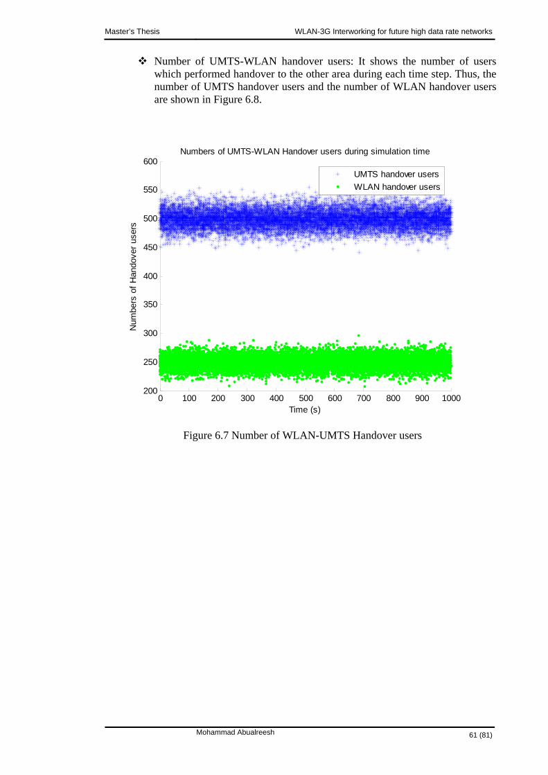
Master’s Thesis WLAN-3G Interworking for future high data rate networks
Number of UMTS-WLAN handover users: It shows the number of users which performed handover to the other area during each time step. Thus, the number of UMTS handover users and the number of WLAN handover users are shown in Figure 6.8.
Figure 6.7 Number of WLAN-UMTS Handover users
0 100 200 300 400 500 600 700 800 900 1000200
250
300
350
400
450
500
550
600
Time (s)
Num
bers
of H
ando
ver u
sers
Numbers of UMTS-WLAN Handover users during simulation time
UMTS handover usersWLAN handover users
Mohammad Abualreesh 61 (81)

Master’s Thesis WLAN-3G Interworking for future high data rate networks
Number of UMTS-WLAN dropped users: It shows the number of users which dropped in each area during each time step. Thus, the number of UMTS dropped users and the number of WLAN dropped users are shown in Figure 6.8.
Figure 6.8 Number of WLAN-UMTS Dropped users
0 100 200 300 400 500 600 700 800 900 1000200
250
300
350
400
450
500
550
600
Time (s)
Num
bers
of D
ropp
ed u
sers
Numbers of UMTS-WLAN Dropped users during simulation time
UMTS dropped usersWLAN dropped users
Mohammad Abualreesh 62 (81)

Master’s Thesis WLAN-3G Interworking for future high data rate networks
Handover delay: it shows the handover delay for each interworking method: the mobile IP method, the gateway method, and the emulator method as shown in Figure 6.9.
Figure 6.9 Handover delay for different WLAN-UMTS Interworking methods
660 680 700 720 740 760 780 800 82030
40
50
60
70
80
90
Number of Users
Han
dove
r del
ay (m
s)UMTS-WLAN Handover Delay
MobileIPGatewayEmulator
6.4.4 Discussion
From the simulation results in the previous section, the performance of the interworking methods is clear from Figure 6.10. The mobile IP method has the highest handover de-lay, while the gateway method has lower delay and the emulator method has the lowest. This result confirms the expected result that was obtained analytically earlier in section 6.3.2 and section 6.3.3.
The mobile IP method suffers from high handover delay since the handover occurs among two networks. The usage of the gateway in the gateway method fastens the handover. However, in the emulator method, the handover occurs in the single UMTS network since WLAN is treated as any normal UMTS cell.
The used simulation model is not that much accurate but it gives an approximate estima-tion about the performance of the interworking methods. However, some further modi-fication worth to be done in order to get more accurate results but this left as future work.
Mohammad Abualreesh 63 (81)
Master’s Thesis WLAN-3G Interworking for future high data rate networks
6.5 Summary
The performance of UMTS-WLAN interworking methods (the mobile IP method, the gateway method, and the emulator method) has been illustrated analytically and using simulation throughout this chapter.
Mohammad Abualreesh 64 (81)
Master’s Thesis WLAN-3G Interworking for future high data rate networks
7. SUMMARY & CONCLUSIONS In the previous chapters, the question of UMTS-WLAN interworking has been demon-strated. The focus is on the features, architecture, and evaluation of these internetwork-ing technologies.
The importance of UMTS-WLAN interworking comes to supply the need for public wireless access: to cover the demand for high data-intensive applications and to enable smooth online access to corporate data services in hot spots. This is done by integrating both UMTS and WLAN together to utilize high mobility and high data rate key features together.
Different UMTS-WLAN interworking architecture methodologies are introduced and studied. The main interworking methods are: the mobile IP method, the gateway method, and the emulator method. The performance of the interworking methods can be evaluated using several performance metrics. The metric used here is the handover de-lay. Theses methods have been evaluated analytically and via simulation; based on handover delay.
As a comparison, based on consequences of the analytical and simulated models, the mobile IP method has the highest handover delay, while the gateway method has lower handover delay and the emulator method has the lowest. Mobile IP method suffers from high handover delay since the handover occurs between two networks. The usage of gateway in the gateway method fastens the handover. However, in the emulator method, the handover occurs in the single UMTS network since WLAN is treated as any normal UMTS cell. These results are confirmed based on literature studies which show the same results for the interworking methods
This research provides an analytical model and a simulated model which can be used for evaluating the performance of UMTS-WLAN interworking method: mobile IP method, the gateway method, and emulator method.
The used simulation model is not that much accurate but it gives an approximate estima-tion about the direction of the performance of the interworking methods. However, some further modification worth to be done in order to get more accurate results but this left as future work. There are still some open questions, which may be considered in future work since the subject of UMTS-WLAN interworking is still under study. For instance, one future task is to simulate the actual UMTS-WLAN interworking method architectures: protocol, traffic model, hot spots etc in order to study the performance of the different interworking methods more accurately and from different aspects rather than only handover delay.
Mohammad Abualreesh 65 (81)

Master’s Thesis WLAN-3G Interworking for future high data rate networks
8. REFERENCES
[1] URL: http://www.andrew.cmu.edu/user/chan3/3G/overview.html (23.8.2004)
[2] Santhi, K.R., Srivastava V.K., Senthil Kumaran G., Butare A., “Goals of true broad band's wireless next wave (4G-5G) ”, Vehicular Technology Conference, 2003. VTC 2003-Fall. 2003 IEEE 58th , Volume: 4 , 6-9 Oct. 2003, Pages:2317 - 2321
[3] “Third Generation' Mobile Technology”, URL: http://www.cellular.co.za/technologies/3g/3g.htm#IMT-2000 , (14.2.2005)
[4] IMT-2000 project, “What is IMT-2000”, URL: http://www.3gtoday.com/technology/media/ITU-IMT-2000project.pdf , (14.2.2005)
[5] 3G-Generation, URL: http://www.3g-generation.com/ , (14.2.2005)
[6] 3GPP, “3GPP homepage”, URL: http://www.3gpp.org, (14.2.2005)
[7] 3GPP2, “3GPP2 homepage”, URL: http://www.3gpp2.org, (14.2.2005)
[8] 3G tutorial, “Overview of The Universal Mobile Telecommunication System e”, URL: http://www.umtsworld.com/technology/overview.htm , (14.2.2005)
[9] Helsinki University of Technology, “Introduction to 3G”, Internal access document, (14.2.2005)
[10] “UMTS - Universal Mobile Telecommunications System Generation”, URL: http://www.nt.tuwien.ac.at/mobile/projects/UMTS/en/ , (14.2.2005)
[11] 3G Today, URL: http://www.3gtoday.com/index.html , (14.2.2005)
[12] Benny Bing, ‘Wireless Local Area Networks- the new wireless revolution’, - John Wiley & Sons, Inc., 2002, ISBN 0-471-22474-X, pages 1-14.
[13] Allied Telesyn Inc., ‘ WLAN Basics: Primer on Wireless Networking’, URL: http://www.alliedtelesyn.com/corporate/media/whitepapers/wireless_lan_basics_wp_b.pdf , (14.2.2005)
[14] Zhengping Zuo, ‘In building Wireless LANs’, URL: http://www.cse.ohio-state.edu/~jain/cis788-99/ftp/wireless_lans/index.html#1 , (14.2.2005)
Mohammad Abualreesh 66 (81)
Master’s Thesis WLAN-3G Interworking for future high data rate networks
[15] Jui-Hung Yeh, Jyh-Cheng Chen, Chi-Chen Lee , “WLAN standards ”, Potentials, IEEE, Volume 22, Issue 4, Oct.-Nov. 2003, Pages:16 - 22
[16] WLAN standards, URL: http://www.webopedia.com/quick_ref/WLANStandards.asp , (14.2.2005)
[17] 3rd Generation Partnership Project, Technical Specification, “3GPP system to Wire-less Local Area Network (WLAN) interworking; System description (Release 6)”, 3GPP TS 23.234, v6.0.0, (March, 2004)
[18] Honkasalo, H.; Pehkonen, K.; Niemi, M.T.; Leino, A.T.; “WCDMA and WLAN for 3G and beyond”, IEEE Wireless Communications, Volume: 9, 2002, Page(s): 14 – 18
[19] Buddhikot, M.M.; Chandranmenon, G.; Seungjae Han; Yui-Wah Lee; Miller, S.; Salgarelli, L.;”Design and implementation of a WLAN/cdma2000 interworking architec-ture”, Communications Magazine, IEEE, Volume: 41, 2003, Page(s): 90 - 100
[20] Shiao-Li Tsao; Chia-Ching Lin; “Design and evaluation of UMTS-WLAN inter-working strategies”, Vehicular Technology Conference, IEEE, Volume: 2, 2002, Page(s): 777 - 781
[21] Ramjee Parasad, Luis Munos, ‘WLANs and WPANs towards 4G wireless’, - Artech House, Incorporated, 2003, ISBN 1580530907.
[22] Toni Janevski, ‘Traffic analysis and design of wireless IP networks’, - Artech House, Incorporated, 2003, ISBN 1-58053-331-0.
[23] Doufexi, A.; Tameh, E.; Nix, A.; Armour, S.; Molina, A.; “Hotspot wireless LANs to enhance the performance of 3G and beyond cellular networks”, Communications Magazine, IEEE, Volume: 41, 2003, Page(s): 58 - 65
Mohammad Abualreesh 67 (81)

Master’s Thesis WLAN-3G Interworking for future high data rate networks
APPENDIX Here, the simulation which was developed in MATLAB will be described. This in-cludes: simulation parameters, instructions, and code.
The simulation parameters are summarized in Table A.1. These parameters need to be set before starting the simulation.
Table A.1 Simulations Parameters
Parameter UMTS WLAN
Cell Radius (m) 1000 100
Centre coordinates (x,y) (m)
(1000,1000) (2050,1000)
Power of access point (dB)
80 40
Gain of access point (dBi)
100 50
Gain of MS antenna (dBi)
10 5
Frequency (MHz) 2000 2400
Target Threshold (dBm)
-120 -100
Path loss exponent 3.5 3.5
Standard deviation for shadowing
6.5 6.5
Number of users 1000 500
Speed of user (m/s) 20 5
Simulation time (s) 1000
Time step (s) 0.1
To start the simulation, first, browse to the project directory that has the simulation pro-gram, second, rum the main command in MATLAB prompt, then enter the suitable val-ues for the simulations parameters- If no values are entered then the default values be-tween brackets will be set automatically. Finally, wait until the simulation ends and the result figures are drawn. This is illustrated as shown bellow:
>> cd C:\MATLAB7\work\project
Mohammad Abualreesh 68 (81)
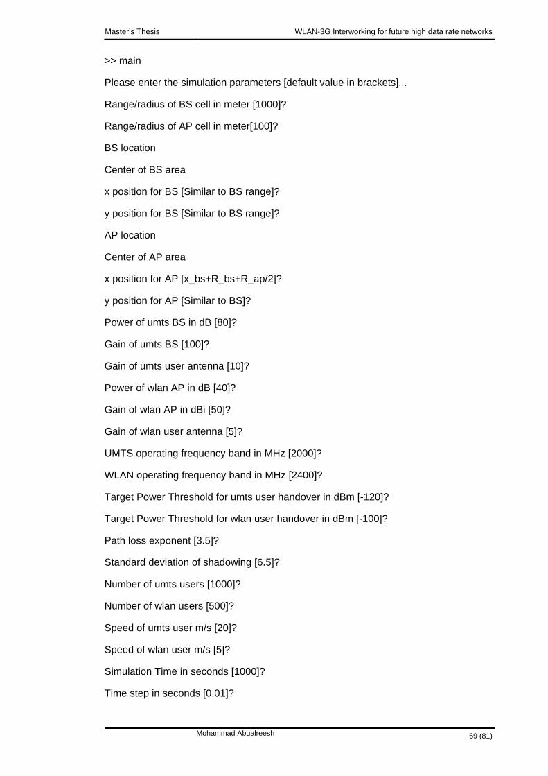
Master’s Thesis WLAN-3G Interworking for future high data rate networks
>> main
Please enter the simulation parameters [default value in brackets]...
Range/radius of BS cell in meter [1000]?
Range/radius of AP cell in meter[100]?
BS location
Center of BS area
x position for BS [Similar to BS range]?
y position for BS [Similar to BS range]?
AP location
Center of AP area
x position for AP [x_bs+R_bs+R_ap/2]?
y position for AP [Similar to BS]?
Power of umts BS in dB [80]?
Gain of umts BS [100]?
Gain of umts user antenna [10]?
Power of wlan AP in dB [40]?
Gain of wlan AP in dBi [50]?
Gain of wlan user antenna [5]?
UMTS operating frequency band in MHz [2000]?
WLAN operating frequency band in MHz [2400]?
Target Power Threshold for umts user handover in dBm [-120]?
Target Power Threshold for wlan user handover in dBm [-100]?
Path loss exponent [3.5]?
Standard deviation of shadowing [6.5]?
Number of umts users [1000]?
Number of wlan users [500]?
Speed of umts user m/s [20]?
Speed of wlan user m/s [5]?
Simulation Time in seconds [1000]?
Time step in seconds [0.01]?
Mohammad Abualreesh 69 (81)

Master’s Thesis WLAN-3G Interworking for future high data rate networks
----------------------
Simulation starts...
----------------------
-------------------------
Iteration number: 1
-------------------------
Number of umts handover users: 495
Number of wlan handover users: 238
Number of umts dropped users: 499
Number of wlan dropped users: 242
Handover delay using MobileIP: 7.952800e+001
Handover delay using Gateway : 4.752820e+001
Handover delay using Emulator: 3.958780e+001
-------------------------
Iteration number: 2
-------------------------
Number of umts handover users: 512
Number of wlan handover users: 231
Number of umts dropped users: 483
Number of wlan dropped users: 251
Handover delay using MobileIP: 8.030100e+001
Handover delay using Gateway : 4.772920e+001
Handover delay using Emulator: 3.968980e+001
-------------------------
……
….
.
The simulation code is shown bellow:
Mohammad Abualreesh 70 (81)

Master’s Thesis WLAN-3G Interworking for future high data rate networks
% Simulation: "Evaluation of UMTS-WLAN Interworking methods: the mobile IP,
% the gateway, and theemulator"
% Programmed by Mohammad Abualreesh
%
%%%%%%%%%%%%%%%% Setting Simulation parameters %%%%%%%%%%%%%%%%%%%%%%%%%%%%
clear;
disp('Please enter the simulation parameters [default value in brackets]...');
R_bs=input('Range/radius of BS cell in meter [1000]? ');
if length(R_bs)==0
R_bs=1000;
end
R_ap=input('Range/radius of AP cell in meter[100]? ');
if length(R_ap)==0
R_ap=100;
end
disp('BS location');
disp('Center of BS area');
x_bs=input('x position for BS [Similar to BS range]?');
if length(x_bs)==0
x_bs=R_bs;
end
y_bs=input('y position for BS [Similar to BS range]?');
if length(y_bs)==0
y_bs=R_bs;
end
disp('AP location');
disp('Center of AP area');
x_ap=input('x position for AP [x_bs+R_bs+R_ap/2]?');
if length(x_ap)==0
x_ap=x_bs+R_bs+R_ap/2;
end
Mohammad Abualreesh 71 (81)

Master’s Thesis WLAN-3G Interworking for future high data rate networks
y_ap=input('y position for AP [Similar to BS]?');
if length(y_ap)==0
y_ap=y_bs;
end
p_bs=input('Power of umts BS in dB [80]? ');
if length(p_bs)==0
p_bs=80;
end
g_bs=input('Gain of umts BS [100]? ');
if length(g_bs)==0
g_bs=100;
end
g_umts=input('Gain of umts user antenna [10]? ');
if length(g_umts)==0
g_umts=10;
end
p_ap=input('Power of wlan AP in dB [40]? ');
if length(p_ap)==0
p_ap=40;
end
g_ap=input('Gain of wlan AP in dBi [50]? ');
if length(g_ap)==0
g_ap=50;
end
g_wlan=input('Gain of wlan user antenna [5]? ');
if length(g_wlan)==0
g_wlan=5;
end
frequency_umts=input('UMTS operating frequency band in MHz [2000]?');
if length(frequency_umts)==0
frequency_umts=2000;
Mohammad Abualreesh 72 (81)

Master’s Thesis WLAN-3G Interworking for future high data rate networks
end
frequency_wlan=input('WLAN operating frequency band in MHz [2400]?');
if length(frequency_wlan)==0
frequency_wlan=2400;
end
umts_threshold=input('Target Power Threshold for umts user handover in dBm [-120]? ');
if length(umts_threshold)==0
umts_threshold=-120;
end
wlan_threshold=input('Target Power Threshold for wlan user handover in dBm [-100]? ');
if length(wlan_threshold)==0
wlan_threshold=-100;
end
alpha=input('Path loss exponent [3.5]?');
if length(alpha)==0
alpha=3.5;
end
sigma=input('Standard deviation of shadowing [6.5]?');
if length(sigma)==0
sigma=6.5;
end
N_umts=input('Number of umts users [1000]? ');
if length(N_umts)==0
N_umts=1000;
end
N_wlan=input('Number of wlan users [500]? ');
if length(N_wlan)==0
N_wlan=500;
end
speed_umts=input('Speed of umts user m/s [20]? ');
if length(speed_umts)==0
Mohammad Abualreesh 73 (81)

Master’s Thesis WLAN-3G Interworking for future high data rate networks
speed_umts=20;
end
speed_wlan=input('Speed of wlan user m/s [5]? ');
if length(speed_wlan)==0
speed_wlan=5;
end
simulation_time=input('Simulation Time in seconds [1000]?');
if length(simulation_time)==0
simulation_time=1000;
end
time_step=input('Time step in seconds [0.01]?' );
if length(time_step)==0
time_step=0.01;
end
%%%%%%%%%%%%%%%% %%%%%%%%%%%%%%%%%%%%%%%%%%%%
%add set available resources in AP/BS
%set umts users locations
r_umts_user=rand(1,N_umts);
phi_umts_user=2*pi*rand(1,N_umts);
% scale by BS radius to get the exact location
for i=1:N_umts
x_umts_user(i)=R_bs*r_umts_user(i)*cos(phi_umts_user(i))+0.01+x_bs; % 0.01 to avoid user at exact location of BS
y_umts_user(i)=R_bs*r_umts_user(i)*sin(phi_umts_user(i))+0.01+y_bs;
end
%set wlan users locations
r_wlan_user=rand(1,N_wlan);
phi_wlan_user=2*pi*rand(1,N_wlan);
% scale by AP radius to get the exact location
for i=1:N_wlan
x_wlan_user(i)=R_ap*r_wlan_user(i)*cos(phi_wlan_user(i))+0.01+x_ap; % 0.01 to avoid user at exact location of AP
Mohammad Abualreesh 74 (81)

Master’s Thesis WLAN-3G Interworking for future high data rate networks
y_wlan_user(i)=R_ap*r_wlan_user(i)*sin(phi_wlan_user(i))+0.01+y_ap;
end
% Plot AP/BS with their users
plot(x_umts_user,y_umts_user, 'b*');
hold on;
plot(x_wlan_user,y_wlan_user, 'g*');
legend('UMTS users','WLAN users');
xlabel('x');
ylabel('y');
axis equal;
%axis([0 x_ap+R_ap+20 0 y_ap+R_ap+20]);
title('Distribution of users among UMTS-WLAN coverasge areas');
hold on;
phi=0:2*pi/100:2*pi;
for i=1:100
x_umts_bs(i)=R_bs*cos(phi(i))+x_bs;
y_umts_bs(i)=R_bs*sin(phi(i))+y_bs;
end
for i=1:100
x_wlan_ap(i)=R_ap*cos(phi(i))+x_ap;
y_wlan_ap(i)=R_ap*sin(phi(i))+y_ap;
end
plot(x_umts_bs,y_umts_bs, 'b-');
hold on;
plot(x_wlan_ap,y_wlan_ap, 'g-');
hold on;
p('----------------------');
disp('Simulation starts...');
disp('----------------------');
Handover_umts_user_number=[];
Mohammad Abualreesh 75 (81)

Master’s Thesis WLAN-3G Interworking for future high data rate networks
Handover_wlan_user_number=[];
Dropped_umts_user_number=[];
Dropped_wlan_user_number=[];
k=1;
for t=0:time_step:simulation_time
Handover_umts_user_number(k)=0;
Dropped_umts_user_number(k)=0;
Handover_wlan_user_number(k)=0;
Dropped_wlan_user_number(k)=0;
%set wlan users speed
v_wlan_user=speed_wlan*rand(1,N_wlan);
phi_v_wlan_user=2*pi*rand(1,N_wlan);
%calculate power level for wlan user
for i=1:N_wlan
dist(i)=sqrt((x_ap-x_wlan_user(i)+v_wlan_user(i)*t*cos(phi_v_wlan_user(i)))^2+(y_ap-y_wlan_user(i)+v_wlan_user(i)*t*sin(phi_v_wlan_user(i)))^2);
p_wlan_user(i)=p_ap+g_ap+g_wlan+alpha*10*log(300./(frequency_wlan*4*pi*dist(i)))+shadow(sigma);
if (p_wlan_user(i) < wlan_threshold)
if (phi_v_wlan_user(i)<=pi/2 | phi_v_wlan_user(i)>= 3*pi/2)
Handover_wlan_user_number(k)=Handover_wlan_user_number(k)+1;
else
Dropped_wlan_user_number(k)=Dropped_wlan_user_number(k)+1;
Mohammad Abualreesh 76 (81)

Master’s Thesis WLAN-3G Interworking for future high data rate networks
end
end
end
%set umts users speed
v_umts_user=speed_umts*rand(1,N_umts);
phi_v_umts_user=2*pi*rand(1,N_umts);
%calculate power level for umts user
for i=1:N_umts
dist(i)=sqrt((x_bs-x_umts_user(i)+v_umts_user(i)*t*cos(phi_v_umts_user(i)))^2+(y_bs-y_umts_user(i)+v_umts_user(i)*t*sin(phi_v_umts_user(i)))^2);
p_umts_user(i)=p_ap+g_ap+g_umts+alpha*10*log(300./(frequency_umts*4*pi*dist(i)))+shadow(sigma);
if (p_umts_user(i) < umts_threshold)
if (phi_v_umts_user(i)<=pi/2 | phi_v_umts_user(i)>= 3*pi/2)
Handover_umts_user_number(k)=Handover_umts_user_number(k)+1;
else
Dropped_umts_user_number(k)=Dropped_umts_user_number(k)+1;
end
end
end
hand-over_delay_mobileIP(k)=handover_delay('mobileIP',Handover_umts_user_number(k)+Handover_wlan_user_number(k));
Mohammad Abualreesh 77 (81)

Master’s Thesis WLAN-3G Interworking for future high data rate networks
handover_delay_gateway(k) =handover_delay('gateway',Handover_umts_user_number(k)+Handover_wlan_user_number(k));
hand-over_delay_emulator(k)=handover_delay('emulator',Handover_umts_user_number(k)+Handover_wlan_user_number(k));
disp('-------------------------');
fprintf('Iteration number: %d\n',k);
disp('-------------------------');
fprintf('Number of umts handover users: %d\n',Handover_umts_user_number(k));
fprintf('Number of wlan handover users: %d\n',Handover_wlan_user_number(k));
fprintf('Number of umts dropped users: %d\n',Dropped_umts_user_number(k));
fprintf('Number of wlan dropped users: %d\n',Dropped_wlan_user_number(k));
fprintf('Handover delay using MobileIP: %d\n', handover_delay_mobileIP(k));
fprintf('Handover delay using Gateway : %d\n', handover_delay_gateway(k));
fprintf('Handover delay using Emulator: %d\n', handover_delay_emulator(k));
k=k+1;
end
% Draw Numbers of UMTS-WLAN Handover users during simulation time
t=0:time_step:simulation_time;
figure;
hold on;
plot(t,Handover_umts_user_number, 'b*');
hold on;
plot(t,Handover_wlan_user_number, 'g.');
legend('UMTS handover users','WLAN handover users');
ylabel('Numbers of Handover users');
xlabel('Time (s)');
Mohammad Abualreesh 78 (81)

Master’s Thesis WLAN-3G Interworking for future high data rate networks
title('Numbers of UMTS-WLAN Handover users during simulation time');
hold on;
% Draw Numbers of UMTS-WLAN Dropped users during simulation time
t=0:time_step:simulation_time;
figure;
hold on;
plot(t,Dropped_umts_user_number, 'b*');
hold on;
plot(t,Dropped_wlan_user_number, 'g.');
legend('UMTS dropped users','WLAN dropped users');
ylabel('Numbers of Dropped users');
xlabel('Time (s)');
title('Numbers of UMTS-WLAN Dropped users during simulation time');
hold on;
% Draw UMTS-WLAN Handover Delay
figure;
hold on;
total_handover=Handover_umts_user_number+Handover_wlan_user_number;
plot(total_handover,handover_delay_mobileIP, 'b*');
hold on;
plot(total_handover,handover_delay_gateway, 'g*');
hold on;
plot(total_handover,handover_delay_emulator, 'r*');
legend('MobileIP','Gateway','Emulator');
ylabel('Handover delay (ms)');
xlabel('Number of Users');
title('UMTS-WLAN Handover Delay');
hold on;
%******* end of main file *********
%%%%%%%%%%%%%%%%%%%%%%%
Mohammad Abualreesh 79 (81)

Master’s Thesis WLAN-3G Interworking for future high data rate networks
% This function calculates the distance between two points: (x1,y1)&(x2,y2)
function d = distance(x1,y1,x2,y2)
d = sqrt((x2-x1)^2+(y2-y1)^2);
%******* end of distance file *********
% shadow.m
%% This function generates attenuation of shadowing
%
%
function [x] = shadow(sigma)
r = randn;
x = sigma * r;
%******* end of shadow file *********
%
% This function is used to evaluate an approximate relation using polynomial fitting in % the simulation data from [20]
% handover delay D vs no. of users N
% Mobile IP: D1=22.8671+0.0773N
% Gateway: D2=32.7949+0.0201N
% Emulator: D3=32.1112+0.0102N
%
function params = polyFitting(x,y,n)
psi=[];
X=x';
Y=y';
for j=1:n+1
psi(:,j)=X.^(j-1);
end
params=inv(psi'*psi)*psi'*Y;
%******* end of polyFitting file *********
%Simulation data used in polynomial fitting from [20]
Mohammad Abualreesh 80 (81)
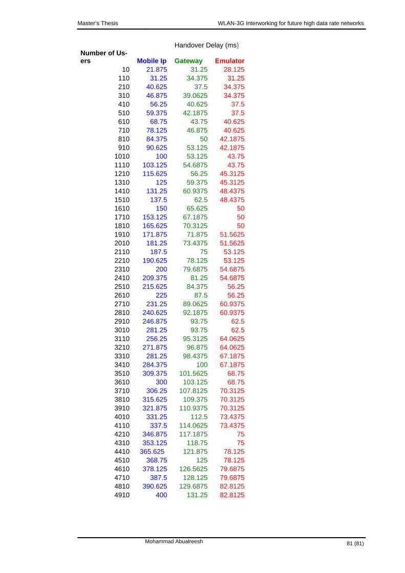
Master’s Thesis WLAN-3G Interworking for future high data rate networks
Handover Delay (ms) Number of Us-ers Mobile Ip Gateway Emulator
10 21.875 31.25 28.125110 31.25 34.375 31.25210 40.625 37.5 34.375310 46.875 39.0625 34.375410 56.25 40.625 37.5510 59.375 42.1875 37.5610 68.75 43.75 40.625710 78.125 46.875 40.625810 84.375 50 42.1875910 90.625 53.125 42.1875
1010 100 53.125 43.751110 103.125 54.6875 43.751210 115.625 56.25 45.31251310 125 59.375 45.31251410 131.25 60.9375 48.43751510 137.5 62.5 48.43751610 150 65.625 501710 153.125 67.1875 501810 165.625 70.3125 501910 171.875 71.875 51.56252010 181.25 73.4375 51.56252110 187.5 75 53.1252210 190.625 78.125 53.125
200 79.6875 54.68752310 2410 209.375 81.25 54.68752510 215.625 84.375 56.252610 225 87.5 56.252710 231.25 89.0625 60.93752810 240.625 92.1875 60.93752910 246.875 93.75 62.53010 281.25 93.75 62.53110 256.25 95.3125 64.06253210 271.875 96.875 64.06253310 281.25 98.4375 67.18753410 284.375 100 67.18753510 309.375 101.5625 68.753610 300 103.125 68.753710 306.25 107.8125 70.31253810 315.625 109.375 70.31253910 321.875 110.9375 70.31254010 331.25 112.5 73.43754110 337.5 114.0625 73.43754210 346.875 117.1875 754310 353.125 118.75 754410 365.625 121.875 78.1254510 368.75 125 78.1254610 378.125 126.5625 79.68754710 387.5 128.125 79.6875
390.625 129.6875 82.81254810 4910 400 131.25 82.8125
Mohammad Abualreesh 81 (81)