Embed Size (px)
Citation preview

WL3 FirewallTechnical Manual

WL3 Technical Manual - Version 1, July 2014
2 3
DeclarationWaterlogic International Ltd
1. The installation, maintenance and sanitizing procedures must be carried out by persons trained by Waterlogic International or their approved distributors. Do not remove any panels or covers unless acceptable in this instruction.2. When any abnormal case happens, firstly unplug the appliance.3. This appliance is not intended for use by persons (including children) with reduced physical, sensory or mental capabilities, or lack of experience and knowledge, unless they have been given supervision or instruction concerning the use of the appliance by a person responsible for their safety. 4. Children should be supervised to ensure that they do not play with the appliance. 5. This appliance can be used by children aged from 8 years and above if they have been given supervision or instruction concerning use of the appliance in a safe way and if they understand the hazards involved. Cleaning and user maintenance shall not be made by children unless they are older than 8 and supervised. Keep the appliance and its power cord out of reach of children aged less than 8 years. 6. Appliances can be used by persons with reduced physical, sensory or mental capabilities or lack of experience and knowledge if they have been given supervision or instruction concerning use of the appliance in a safe way and understand the hazards involved. 7. Children must not play with the appliance. 8. If the supply cord or the detachable cord sets are damaged, it must be replaced by the manufacturer, its service agent or a similarly qualified person in order to avoid a hazard.9. The detachable hose-sets and the connection kit used to connect the main water are supplied by the technician. Don’t reuse the old ones. 10. The appliance is to be supplied through a residual current device (RCD) having a rated residual operating current not exceeding 30mA.11. This appliance is intended to be used in household and similar applications such as - staff kitchen areas in shops, offices and other working environments; - farm houses and by clients in hotels, motels and other residential type environments; - bed and breakfast type environments; - catering and similar non-retail applications.12. This appliance contains a UV-C emitter (UV lamp)13. Unintended use of the appliance or damage to the housing may result in the escape of dangerous UV-C radiation. UV-C radiation may, even in little doses, cause harm to the eyes and skin. 14. Appliances that are obviously damaged must not be used. 15. The replacement of the UV lamp must be carried out by personnel trained by Waterlogic International or their approved distributors. 16. Read the maintenance instructions before opening the appliance.17. The appliance must be disconnected from the power supply before replacing the UV lamp. 18. The UV lamp must be replaced at 6 month intervals or when necessary. If the unit is placed in a high use area, the UV lamp will need to be replaced more frequently. The quartz spiral can be cleaned by using an ultrasonic bath if needed.19. WARNING: Do not operate the UV lamp when it is removed from the appliance enclosure.
Technical Manual
Welcome to your new Waterlogic machine.
This Technical Manual is to help you get great tasting water cup
after cup by making the most of the product’s features.
Machine Overview 4Mains Parts Layout - Cold, Hot and Sparkling 8Mains Parts Layout - Cold, Hot and Ambient 9Mains Parts Layout - Cold and Ambient 10Mains Parts Layout - Cold, Ambient and Sparkling 11Carbonation Tank 12Pre Delivery Inspection Procedures (PDI) 13Installation Procedures 15Instructions on Changing the CO2 Bottle 17Operating Instructions 19Maintenance and Servicing 22Sanitising or Descaling 23Fault Finding 26Advisory Icons 26Technical Specifications and Warranties 28End of Life 30ROHS 30BioCote® 30Electrical Wiring Diagram 230V 31Wetted Parts Illustration - Hot, Cold and Sparkling 34Main Parts List Illustration - Exploded View 36
Index
WL3 Technical Manual - Version 1, July 2014
4 55
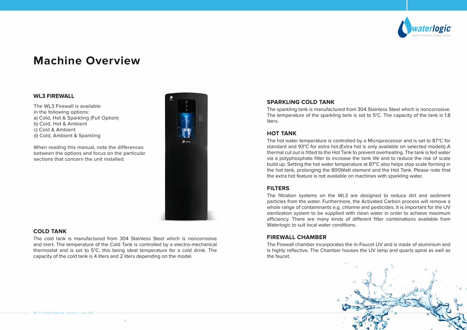
Machine Overview
WL3 FIREWALLSPARKLING COLD TANKThe sparkling tank is manufactured from 304 Stainless Steel which is noncorrosive. The temperature of the sparkling tank is set to 5°C. The capacity of the tank is 1.8 liters.
HOT TANKThe hot water temperature is controlled by a Microprocessor and is set to 87°C for standard and 93°C for extra hot.(Extra hot is only available on selected models) A thermal cut out is fitted to the Hot Tank to prevent overheating. The tank is fed water via a polyphosphate filter to increase the tank life and to reduce the risk of scale build up. Setting the hot water temperature at 87°C also helps stop scale forming in the hot tank, prolonging the 800Watt element and the Hot Tank. Please note that the extra hot feature is not available on machines with sparkling water.
FILTERSThe filtration systems on the WL3 are designed to reduce dirt and sediment particles from the water. Furthermore, the Activated Carbon process will remove a whole range of contaminants e.g. chlorine and pesticides. It is important for the UV sterilization system to be supplied with clean water in order to achieve maximum efficiency. There are many kinds of different filter combinations available from Waterlogic to suit local water conditions.
FIREWALL CHAMBER The Firewall chamber incorporates the in-Faucet UV and is made of aluminium and is highly reflective. The Chamber houses the UV lamp and quarts spiral as well as the faucet.
The WL3 Firewall is available in the following options:a) Cold, Hot & Sparkling (Full Option)b) Cold, Hot & Ambientc) Cold & Ambientd) Cold, Ambient & Sparkling
When reading this manual, note the differences between the options and focus on the particular sections that concern the unit installed.
COLD TANKThe cold tank is manufactured from 304 Stainless Steel which is noncorrosive and inert. The temperature of the Cold Tank is controlled by a electro-mechanical thermostat and is set to 5°C, this being ideal temperature for a cold drink. The capacity of the cold tank is 4 liters and 2 liters depending on the model.
WL3 Technical Manual - Version 1, July 2014

WL3 Technical Manual - Version 1, July 2014
6 7
WATER VALVESDispensing of water to the customer is achieved by means of a 24V DC electrical solenoid valve. The valves are energized every time the customer touches the dispense button for a drink. DC voltage is used to give a positive and quieter action of the solenoid valve.
PLASTIC PANELSThe molded panels are made from recyclable ABS plastic. All the ABS plastic panels are UV resistant and meet the standards of CE and UL. Please note that the WL3 should not be exposed to direct sunlight. Placing the WL3 in direct sunlight from a window, close to a radiator, or in a room of high ambient temperature, will affect the efficiency of the refrigeration circuit
PARTS REQUIRED FOR SPARKLING WATERCO2 Cylinder & Gas Regulator: The units with the option of sparkling water will need CO2 gas, food grade carbon dioxide. This gas is stored in cylinders in a liquid form. The cylinders are usually painted grey or black (regulation requirement for CO2). The gas regulator, which comes with the unit, controls the flow of CO2 to the carbonation tank; it reduces the pressure of the CO2 gas to 3bar which is needed to make high quality sparkling water. Water Pump: The water pump is 24V DC and forces the pre-chilled cold still water into the carbonation tank at a minimum pressure of 3.2 bar. This pressure is required to overcome the internal pressure from the CO2 gas which is in the tank.
IN FAUCET UVThe Unique design allows the faucet area to be sterilized before, during and after every dispense. There are two types of sensors available, the CDS UV sensor that detects if the UV lamp is working and the UV sensor that monitors the UVC intensity from the UV lamp.
UV LAMPThe UV light is a 13Watt germicidal lamp at a wavelength of 253.7 NM, which is very efficient at destroying bacteria in water. The UV lamp is situated in the Firewall Chamber surrounded by a quartz spiral that attains NSF standard 55 purification of water. The UV lamp must be replaced at 6 months intervals, and the quartz spiral cleaned by using an ultrasonic bath if needed.
PCBThe PCB (Printed Circuit Board) is the control unit for the WL3, it is responsible for the functions of all the mechanical and electrical parts (24V DC) including the solenoid valves, touch panel, LED’s and pump.
COMPRESSORThe compressor operates at 220-240V at 50Hz. It uses 60-72 grams of R134a non-Ozone depleting refrigerant gas depending on the model type.
WATER PIPES AND FITTINGSThe inlet and the internal water circuit pipe size is 1/4” and 5/16”. The entire internal water circuit and all the components which come in contact with water are food grade NSF approved. The Cold, Ambient and Sparkling water tubing inside the machine should not be exposed to water above 25˚C.

WL3 Technical Manual - Version 1, July 2014
8 9
Wetted Parts Layout Cold, Hot and Sparkling
Wetted Parts Layout Cold, Hot and Ambient
DRAINVALVE
SOLENOIDVALVE
SOLENOIDVALVE
FILTERDRYER
HOTTANK
COMPRESSOR
CONDENSER
FILT
ER
IN (Water)
SOLENOIDVALVE
WAT
ER IN
SPARKLING WATER OUT
SOLENOIDVALVE
PUMPCHECKVALVE
CO2 In
SPARKLINGTANK
SAFETYVALVE
COLDSENSOR
COLDTANK
SUCK BACK
SOLENOIDVALVE
CHECK VALVE
HOT WATER OUTHOT WATER OUT
AIR VENT
SOLENOIDVALVE
SOLENOIDVALVE
DRAINVALVE
SOLENOIDVALVE
SOLENOIDVALVE
FILTERDRYER
HOTTANK
COMPRESSOR
CONDENSER
FILT
ER
IN (Water)
SOLENOIDVALVE
SOLENOIDVALVE
HOT WATER OUT
AIR VENT
COLDSENSOR
COLDTANK
AMBIENT WATER OUT
COLD WATER OUT

WL3 Technical Manual - Version 1, July 2014
10 11
DRAINVALVE
SOLENOIDVALVE
SOLENOIDVALVE
FILTERDRYER
COMPRESSOR
CONDENSER
FILT
ER
IN (Water)
WAT
ER IN
SOLENOIDVALVE
PUMPCHECKVALVE
CO2 In
SPARKLINGTANK
SAFETYVALVE
SOLENOIDVALVE
SPARKLING WATER OUT
COLDSENSOR
COLDTANK
SOLENOIDVALVE
SUCK BACK
SOLENOIDVALVE
CHECK VALVE
AMBIENT WATER OUT
COLD WATER OUT
SOLENOIDVALVE
Wetted Parts Layout Cold, Ambient and Sparkling
Wetted Parts Layout Cold and Ambient
DRAINVALVE
SOLENOIDVALVE
SOLENOIDVALVE
FILTERDRYER
COMPRESSOR
CONDENSER
FILT
ER
IN (Water)
SOLENOIDVALVE
AMBIENT WATER OUT
COLD WATER OUT
COLDSENSOR
COLDTANK

12 13
Carbonation Tank Pre Delivery Inspection Procedures (PDI)
CAUTION:Only competent trained technicians should work on Waterlogic products.Waterlogic units may weigh over 25KG. We recommend caution when lifting.Packing materials could present a trip hazard. Keep them off the floor.Take care not to allow the power lead to get wet. If the lead gets wet it must not be used.CO2 gas cylinders used for sparkling units are under high pressure and should be handled carefully and all safety instructions should be followed.For Hot and Cold units, omit section 8, 10, 12.For Cold and Sparkling units, omit section 13, 15.
WL3 Technical Manual - Version 1, July 2014

WL3 Technical Manual - Version 1, July 2014
14 15
1. Remove packing straps and unpack unit and visually inspect for any damage.
(Report any defects to Waterlogic as soon as possible).2. Place the unit on a suitable work bench or leave on the floor for free standing models.
3. Open the top cover by removing the two screws that fix it in place.
4. Visually inspect all electrical connections and power lead.
5. Visually inspect all water connections.
6. Remove the three screws on top of the Firewall Chamber and inspect the quartz spiral for damage and re-assemble.
7. Connect to a potable drinking water supply via a 1/4” John Guest tube, the supply must be limited to 3 bar.
8. Connect to a CO2 gas regulator via a 1/4” John Guest tube and set to 3 bar.
9. Connect the power cord to an appropriate power supply and the machine.
10. Turn the CO2 on and lift the yellow safety valve for 5 seconds.
11. Replace the top cover and re-fit the screws.
12. Once the power, water and CO2 are all turned on the unit will auto fill the sparkling water tank.
13. Note that if the machine has a hot option, the hot tank must be filled before any other tank.
14. Select the hot + extra hot button until water flows clearly.
15. Select the cold button until water flows clearly.
16. After cold/hot has filled, turn on heater/compressor switch allow up to an hour for the unit to heat and chill. Test water temperatures and ensure the water tastes acceptable.
17. Check all WL3 functions.
18. Turn off power, water and CO2 if a sparkling unit.
19. Turn unit around and drain from rear drain valves if fitted.
20. Clean and repack ready for dispatch.
21. Waterlogic recommend that all units are fully electrically (PAT) tested on site by the commissioning engineer as damage may have occurred during transit to the unit’s final destination.
Installation Procedures
1. Check and assemble the WL3 base cabinet if required to do so.
2. Mount the WL3 Firewall on a firm, level surface so the machine cannot topple or fall over. A 50mm air gap is required the whole way around the machine to allow for sufficient ventilation. The WL3 must not be installed in direct sunlight, adjacent to a heat source, or in an ambient room where the temperature is above 30°C or below 5°C.
3. Level the machine using the adjustable feet if needed.
4. It is advisable to have the power and water supply within a 2 metre range of the machine, the isolation for the water and electricity should be easily accessible. The supply of water must be from a potable source and the machine should not be installed using an extension lead.
5. Remove the top cover of the machine. If you are installing a freestanding machine also remove the lower base cover. This is retained by two screws located under the front edge at the bottom of the cover and two clips in the same location. Remove the screws and push clips up to release it. Inspect all water and electrical and water connections to make sure they have not come loose whilst in transit.
6. If you are installing a carbonated machine then please follow this step, if not proceed to step 7. Prepare the CO2 cylinder first by removing the dust cap (if there is one in place), then face the cylinder away from you and purge some of the gas for two seconds to clear any dust or dirt from the nozzle prior to fitting the CO2 pressure regulator. Attach the CO2 pressure regulator to the CO2 cylinder and then attach to the WL3 Firewall CO2 ‘IN’ bulkhead connector using 1/4” flexible pipe. Turn on the CO2 gas bottle. The pressure regulator should be pre-set at 45 PSI (3 bar). If the pressure reading is higher or lower than 45 PSI, then please adjust it to the correct setting. The CO2 bottle should be secured inside the base cabinet, or secured within a cabinet adjacent to the WL3 Firewall, so the cylinder cannot fall over.
7. Remove the inline filter from the machine and attach a water feed directly into the inlet side, attach another length of water pipe to the outlet side and direct this into a bucket or a large container. Allow 10 litres of water to pass through the filter clearing any carbon fines that may need to be flushed out. (This process may need to be repeated).
Pre Delivery Inspection Procedures (PDI)

WL3 Technical Manual - Version 1, July 2014
16 17
8. Make the water connection using an installation kit. Waterlogic recommends the use of a pressure reducing valve, a shut off valve and a non return valve. These should be fitted before the water intake to the machine. Minimum operating pressure for the machine to work suitably is 2.6bar. The minimum incoming flow rate is 1.2 litres per minute. The ideal operating pressure is at 3bar, and at pressures higher than 3.2bar the machine will not function correctly and this can lead to leaks. The water should be from a potable source and should be allowed to run clear of any sediment before making the connection into the WL3 Firewall.
9. Check all the connections to ensure there are no water or CO2 leaks within the WL3 Firewall machine.
10. Check the electrical wall socket (polarity) and then make the electrical connection to the WL3 by plugging the power lead into the socket on the rear of the WL3. Then connect it to the electrical feed or wall power outlet. Turn on the power supply to the WL3.
11. Re-fit the top and bottom covers and secure them using the screws removed earlier, then turn on the red power switch. The WL3 will go through a self-test cycle and the LED’s will light automatically. When the self-test cycle completes, the sparkling water model will automatically fill with water, whilst still water models will need to be manually flushed by depressing the hot dispense button first or the cold water dispense button. When the WL3 has completed filling flush through 10 litres of water by depressing the hot, cold and sparkling buttons. Make sure the hot tank is full of water and turn on the green heater and compressor switch at the rear of the machine, the WL3 Firewall will then begin to cool and heat.
12. The water temperatures are pre-set at the factory to 5°c for the cold water and 87°c for the hot water.
13. The water should now be taste tested, any hint of a taste in the water means the machine needs to be flushed further with an additional 10 litres and then taste tested again.
14. The WL3 Firewall should be sanitized at installation.
1. Turn off the empty CO2 cylinder and disconnect the CO2 pressure regulator.
2. With the new bottle, remove the dust cap (if there is one in place), aiming the valve away from you. Momentarily open the valve and purge some of the CO2 gas to remove any dirt or dust that may have entered the nozzle.
3. Check that the rubber O-ring has not fallen out of the CO2 pressure regulator when it has been removed from the empty CO2 cylinder. If it is still correctly in place then attach the CO2 pressure regulator to the new bottle and connect via a length of ¼” flexible hose to the WL3 Firewall.
4. Open the valve slowly simultaneously with step 5 below and observe the gauge reading on the regulator, it should be at 3bar of pressure as this setting is pre-set, but if not adjust were necessary.
5. Lift the yellow lever under top cover for 4-6 seconds to purge the gas line and carbonator.(This must be done when you open the CO2 cylinder valve so that the tank is not damaged when initially pressured)
6. Place a container of at least 5 litres under the faucet and dispense sparkling water until just the CO2 gas is being dispensed from the faucet. The WL3 will now refill. This takes approximately 4 minutes. When the pump has stopped turn the CO2 gas bottle off.
7. Record the regulator pressure, normally 3 Bar. After 5 minutes check the gauge for any pressure drop as this indicates a leak and turn the CO2 back on following this procedure. (DO NOT LEAVE THE MACHINE WITHOUT CHECKING THE CO2 IS SWITCHED ON!!!)
Instructions on Changing the CO2 Bottle
WL3 Technical Manual - Version 1, July 2014
18 19
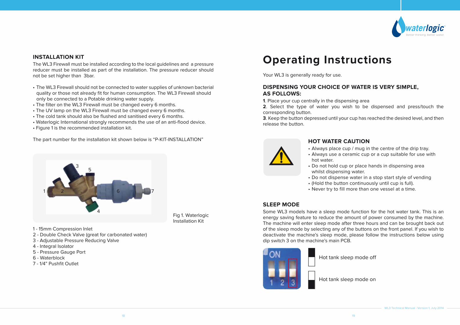
INSTALLATION KITThe WL3 Firewall must be installed according to the local guidelines and a pressure reducer must be installed as part of the installation. The pressure reducer should not be set higher than 3bar.
•TheWL3Firewallshouldnotbeconnectedtowatersuppliesofunknownbacterial quality or those not already fit for human consumption. The WL3 Firewall should only be connected to a Potable drinking water supply.•ThefilterontheWL3Firewallmustbechangedevery6months.•TheUVlampontheWL3Firewallmustbechangedevery6months.•Thecoldtankshouldalsobeflushedandsanitisedevery6months.•WaterlogicInternationalstronglyrecommendstheuseofananti-flooddevice.•Figure1istherecommendedinstallationkit.
The part number for the installation kit shown below is “P-KIT-INSTALLATION”
Fig 1. Waterlogic Installation Kit
1 - 15mm Compression Inlet2 - Double Check Valve (great for carbonated water)3 - Adjustable Pressure Reducing Valve4 - Integral Isolator5 - Pressure Gauge Port6 - Waterblock7 - 1/4” Pushfit Outlet
Your WL3 is generally ready for use.
DISPENSING yOUR CHOICE OF WATER IS VERy SIMPLE, AS FOLLOWS:1. Place your cup centrally in the dispensing area2. Select the type of water you wish to be dispensed and press/touch the corresponding button.3. Keep the button depressed until your cup has reached the desired level, and then release the button.
SLEEP MODESome WL3 models have a sleep mode function for the hot water tank. This is an energy saving feature to reduce the amount of power consumed by the machine. The machine will enter sleep mode after three hours and can be brought back out of the sleep mode by selecting any of the buttons on the front panel. If you wish to deactivate the machine’s sleep mode, please follow the instructions below using dip switch 3 on the machine’s main PCB.
Operating Instructions
HOT WATER CAUTION•Alwaysplacecup/muginthecentreofthedriptray.•Alwaysuseaceramiccuporacupsuitableforusewith hot water.•Donotholdcuporplacehandsindispensingarea whilst dispensing water.•Donotdispensewaterinastopstartstyleofvending•(Holdthebuttoncontinuouslyuntilcupisfull).•Nevertrytofillmorethanonevesselatatime.1 2 6
4
7
35
Hot tank sleep mode off
Hot tank sleep mode on

WL3 Technical Manual - Version 1, July 2014
20 21
Operating Instructions
HOT
COLD WATERPress the cold water button. Cold water will be dispensed.
AMBIENT WATERPress the ambient water but-ton. Ambient water will be dis-pensed.
SPARKLING WATERPress the sparkling water but-ton. Sparkling water will be dis-pensed.
EXTRA HOT WATERHold down the hot button until the button starts flashing. This means that the water is now heating to the extra hot temperature. Once the button stops flashing, press and hold the hot water button and simultaneously press the ambient button below it. Extra hot water will dispense.
HOT HOT
HOT
HOT WATERPress and hold the hot wa-ter button and simultaneously press ambient button below it (This safety feature prevents hot water from being dispensed accidentally, especially by chil-dren). Hot water will dispense.
COLD, AMBIENT & SPARKLING
COLD & AMBIENT
COLD, HOT & AMBIENT
COLD, HOT & SPARKLING
HOTHOT

WL3 Technical Manual - Version 1, July 2014
22 23
Maintenance and Servicing•EverysixmonthsitisstronglyrecommendedthattheUVlampandfiltersbechanged.•TheFirewallquartzspiralneedstoberemoved,inspectedandcleanedwherenecessary.•AWL3Firewallwithahotwateroptionmayrequireanycalciumbuildupinthehot tank to be removed, this depends on local water conditions•NopaperworkorcleaningrecordsshouldbestoredinsidetheWL3Firewall.
1. You will need to stop the water supply to the machine by turning the isolation valve to the off position and releasing the pressure by depressing the cold water button until the water stops being dispensed.
2. Isolate the power to the WL3 Firewall by turning the red and green power switches off, these are located at the rear of the machine. Remove the power lead as a second safety precaution.
3. The filter is located in the WL3 Firewall base cabinet behind the lower front panel or within the top front panel if it is a mini model.
4. To replace the filter detach the water pipes from the elbow fittings at the top, then the filter can then be removed from the retaining bracket. Unscrew the filter housing by twisting it clockwise, this will expose the carbon cartridge. The cartridge can then be removed from the filter housing and replaced.
5. The new filter will require flushing prior to being re-fitted in the WL3 Firewall. To do this connect a water feed directly into the inlet side of the filter and attach another length of pipe to the outlet side and direct this into a bucket/large container or drain, then flush through 10 litres of water to ensure that any loose carbon fines are fully removed from the filter to avoid any damage being caused to the machine.
6. After the filter has been flushed it can be replaced in the WL3 Firewall and the water pipes can be reconnected.
7. Remove the UV lamp by unplugging the UV loom connector and pulling the lamp upwards. Then undo the three screws and remove the top cover of the Firewall housing and the quartz spiral.
8. Check the spiral for any scale build up and clean were necessary.
9. Examine the UV loom for any discolouration or wear, if there is any visible remove the loom and replace with a new one.
10. Replace the quartz spiral and reconnect and replace the UV lamp assembly and Firewall housing, making sure not to touch the new UV lamp with bare hands as this will shorten the life of the lamp.
11. Inspect all of the electrical and water connections on the machine, and take any action necessary to prevent a fault from occurring.
12. Check the faucet nipple for any calcium build up or any visible damage and clean or replace it if necessary.
13. Reassemble the machine and secure all panels with screws.
14. Check that the air gap around the machine is sufficient and there is nothing blocking the ventilation.
15. Reconnect the power to the machine and turn the red switch at the rear of the machine to the ‘on’ position.
16. Flush through 5 litres of hot and cold water and if there is the option, 5 litres of sparkling water to ensure the water is running clear of any carbon fines and that the taste of the water is clean and to the customers satisfaction. If you are not happy with the quality of the water continue to flush an additional 2-5 litre of water until you are satisfied with the taste.
17. The green heater and compressor switch can now be turned on, allow the machine to heat and cool the water.
18. Clean the outside of the machine with a non-abrasive anti-bacterial wipe or cloth.
19. Taste the water one final time and check it is cooling and heating the water.
SANITISINGYou will need the following items:
•AnemptyWaterlogicinlinefilterhousing•Rubbergloves•Antibacterialwipesorspray•Teststrips•Acrossheadscrewdriver•Sanitisationfluid•Acontainer
1. Put on the rubber gloves to minimise the chance of any contamination to the machine and to protect yourself whilst the sanitisation procedure is being carried out.
2. Turn off the water supply to the machine and release the internal pressure by pushing the cold button until the cold water stops being dispensed. Then disconnect the water feed pipe from the bulkhead at the rear of the machine.

WL3 Technical Manual - Version 1, July 2014
24 25
3. Measure 45ml of Aqua Dosa sanitising fluid into the empty filter housing and securely fasten the filter head.
4. Insert the water feed pipe into the inlet fitting of the inline filter housing containing sanitisation fluid. Attach a length of ¼” water pipe into the outlet fitting and insert the other end of the pipe into the bulkhead at the rear of the machine.
5. Remove the filter cartridge from the filter inside of the machine to avoid the mixing of sanitisation fluid and the active carbon, reattach the filter head securely. (The filter head can also be bypassed during sanitisation)
6. The water supply to the machine can now be turned on.
7. Dispense cold water until the sanitisation fluid leaves the faucet, this can be checked by pressing the cold button until the colour of the test strip has changed to indicate the presence of the Sani fluid (Normally about 400-500ml of water needs to be dispensed). If the machine has a carbonated option depress the cold button until 200ml of water has been dispensed and then depress the carbonated button and dispense the same amount of water, use the test strips to ensure the sanitisation fluid has reached the cold and the sparkling tanks. Do not let any sanitisation fluid enter the hot tank.
8. Leave the sanitisation fluid inside the machine for a minimum of 10-15 minutes, when this time has been reached, flush water through the machine until there is no sanitisation fluid left inside. Fit a new filter cartridge into the internal filter and remove the empty filter housing from the back of the machine, connect the water feed pipe directly into the bulkhead and turn the water supply on.
9. Inspect the faucet nipple and clean or replace if it is damaged or if there is a calcium build up around it.
10. Isolate power to the machine, then remove the quartz spiral by undoing the three screws on the top of the Firewall housing, disconnecting the UV sensor and water pipe, and removing the UV lamp. Inspect the spiral for any damage or calcium build up, if there is a large amount of calcium remove and replace the spiral and send it away to be treated by an ultrasonic bath.
11. Using the antibacterial wipes, sufficiently clean the exterior panels of the machine, including the drip tray and grill.
DE-SCALINGYou will need the following items to descale the hot tank.
•A container that can hold 5 litres of water •Funnel or squeeze bottle•Syringe•Star/Phillips screwdriver •Descaling solution
1. Allow the machine to heat the water up to normal operating temperature, as the water inside the tank needs to be hot for the descaling solution to work effectively (Scale Kleen)
2. Isolate the power by disconnecting the power lead at the rear of the machine. Remove the top cover from the machine by undoing the two screws at the back of the lid and lift the panel in an upward motion.
3. Disconnect the silicone tubing from the faucet nipple, leave the other end attached to the outlet at the top of the hot tank.
4. Drain 50-100ml of hot water from the machine into a container, using the drainage valve at the rear of the machine. Then use the hot water from the machine to make your descaling solution, following the manufacturer’s instructions of the descaler.
5. If you are using a syringe then draw up the solution into the syringe and insert it into the open end of the silicone tubing, this should be done slowly as doing this process too quickly can result in the tank overflowing. If doing this with a funnel use the same process except you will pour the solution into the funnel connected to the silicone tube, add the solution in stages to prevent the hot tank overflowing.
6. Allow the solution to remain in the tank for 5 – 10 minutes, re-attach the silicone tubing to the faucet nipple, replace the top cover and then re-connect the power lead, and flush through the hot tank by dispensing water from the hot option. You will need to flush approx. 4-8 litres of water.
7. Open the top cover and check for leaks and then replace the top cover and secure it using the two screws
8. Smell and then taste the water and flush more water through the tank if needed.

WL3 Technical Manual - Version 1, July 2014
26 27
FAULT FINDINGAll fault finding procedures must be carried by a technician trained by Waterlogic International or their nominated distributor. Please take great care and suitable health and safety measures when fault finding on live electrical parts.
ADVISORy ICONS
1. No flow of water: Ensure that there is a water supply to the WL3 Firewall from the building and that the installation isolation valve is turned on. If the installation kit has an anti-leak device included in it (as Waterlogic Installation kit) then make sure it has not tripped.
2. No flow of water: Check that the water filters are not blocked and that they are in date and are screwed home securely into the filter head. Waterlogic recommend filters are changed at 6 months.
3. The hot water is not hot and cold water is not cold: Make sure the green heater compressor switch is turned on.
4. There is hot water flow but cold water is not flowing: This may be due to the cold water tank being frozen. If so disconnect power supply for one hour to allow the tank to defrost, and then flush the cold water system. Check the temperature settings are correct. If the cold tank is not frozen then check the solenoid valve is operating correctly and being turned on and off when you push the cold button.
5. There is cold water flow but hot water is not flowing: This may be due to calcium build up in the hot tank or the hot water outlet. De-scale the hot tank. Check the hot water solenoid valve functions correctly and turns on and off when you hold the hot and extra hot buttons together for 3 seconds.
6. Low flow of cold water or hot water or both: Check the building water pressure to the WL3 Firewall is 45 PSI. Check the filters are not partially blocked, that the solenoid valves function correctly, hot tank calcium build up need to be de-scaled, cold tank ice build up needs to be defrosted.
7. No sparkling water: Ensure the CO2 bottle is full and turned on and set at 45 PSI. Turning the gas pressure above 45 PSI can stop the production of sparkling water. Check the pump Icon. If flashing turn off the power to the WL3 Firewall for 1 minute and then back on to reset the carbonation pump. The pump will time out if it runs for more than 8 minutes continuously.
8. Bad or plastic taste: If the WL3 Firewall is new it may need flushing for a longer period.
9. Water leaks: Most leaks will trip the Waterlogic block located on the installation kit. Should you see water leaking from the WL3, isolate the supply and start normal fault finding procedures.
10. No power: Check the building electrical supply to the WL3 Firewall is on and that the power cord is plugged in. Ensure the red power switch at the rear of the WL3 Firewall is on. Test the WL3 Firewall fuse. If all these points are OK then start normal fault finding procedures.
11. All Icons flashing and audible alarm: An over heat fault has been detected please switch the WL3 Firewall off immediately and start fault finding procedures.
POWER LED This LED shows the machine is connected to mains power and is switched on and live. If this led icon is continuously flashing, this indicates a No Water Supply fault. Check the water supply is turned on; if the fault persists please call your authorised service agent.
FILTRATION LED Filtration is Active.
PURIFICATION LED This led shows the UV lamp is operating correctly. Should this icon be continuously flashing and the machine not dispensing water, then this indicates a UV fault. Please call your authorised service agent.
PROTECTION LED BioCote protection is active.

WL3 Technical Manual - Version 1, July 2014
28 29
Description WL3 FS HCS
WL3 FS HCA WL3 FS CA WL3 FS
CASWL3 M HCA WL3 M CA WL3 M
CASRefrigeration Gas R134a 72g 60g 60g 72g 60g 60g 64g
Cold Tank Capacity 4.0L 4.0L 4.0L 4.0L 2.0L 2.0L 2.0L
Hot Tank Capacity 2L 2L N/A N/A 2L N/A N/A
Sparkling Tank Capacity 1.8L N/A N/A 1.8L N/A N/A 1.8L
CO2 Bottle With Shelf (Max)
520mm(H) x 140mm(D) N/A N/A 520mm(H)
x 140mm(D) N/A N/A N/A
CO2 Bottle Without Shelf (Max)
550mm(H) x
100mm(D)N/A N/A
550mm(H) x
100mm(D)N/A N/A N/A
Water Connection 1/4” Hose 1/4” Hose 1/4” Hose 1/4” Hose 1/4” Hose 1/4” Hose 1/4” Hose
Minimum Water Pressure Megapascal (Bar)
0.26 (2.6) 0.26 (2.6) 0.26 (2.6) 0.26 (2.6) 0.26 (2.6) 0.26 (2.6) 0.26 (2.6)
Maximum Water Pressure Megapascal (Bar)
0.32 (3.2) 0.32 (3.2) 0.32 (3.2) 0.32 (3.2) 0.32 (3.2) 0.32 (3.2) 0.32 (3.2)
Recommended Water Pressure Megapascal (Bar)
0.3 (3.0) 0.3 (3.0) 0.3 (3.0) 0.3 (3.0) 0.3 (3.0) 0.3 (3.0) 0.3 (3.0)
Minimum Incoming Flow Rate (litres per minute)
1.2 lpm 1.2 lpm 1.2 lpm 1.2 lpm 1.2 lpm 1.2 lpm 1.2 lpm
Dispensing Flow Rate 1.6 lpm 1.6 lpm 1.6 lpm 1.6 lpm 1.6 lpm 1.6 lpm 1.6 lpm
Hot Water Temperature 87°C 87°C N/A N/A N/A N/A N/A
Cold Water Temperature 5°C 5°C 5°C 5°C 5°C 5°C 5°C
Sparkling Water Temperature 5°C N/A N/A 5°C N/A N/A 5°C
Description WL3 FS HCS
WL3 FS HCA WL3 FS CA WL3 FS
CASWL3 M HCA WL3 M CA WL3 M
CAS
Machine Size
385mm(W) x
365mm(D) x
1140mm(H)
385mm(W) x
365mm(D) x
1140mm(H)
385mm(W) x
365mm(D) x
1140mm(H)
385mm(W) x
365mm(D) x
1140mm(H)
385mm(W) x
460mm(D) x
486mm(H)
385mm(W) x
460mm(D) x
486mm(H)
385mm(W) x
460mm(D) x
486mm(H)Machine Weight 33Kg 29Kg 27Kg 32Kg 24Kg 22Kg 28Kg
Power Supply 220-240 Volt / 50HzHeater 800W 800W N/A N/A 800W N/A N/ACompressor 130W 130W 130W 130W 130W 130W 130WPump 18W N/A N/A 18W N/A N/A 18WUV Lamp 13W 13W 13W 13W 13W 13W 13WControl Units 19W 17W 17W 19W 17W 17W 19WUnit Total 980W 960W 160W 180W 960W 160W 180W
Technical Specifications and Warranties
SAFETySubject to the standard terms and conditions of sale (a copy of which has been provided to you), neither Waterlogic International Limited (“Waterlogic”), nor any affiliated companies shall be liable for any damage which could affect, directly or indirectly, any person or property.
Please be aware that any warranties accompanying the sale of our products will be invalidated by any of the following:•Incorrectinstallation•IncorrectuseoftheWL3Firewall•Unsuitableelectricalandwatersupply•Majorshort-comingofmaintenance•Technicalinterventionsoralterationsofanunauthorisednature•Adoptionanduseofunapprovedspareparts•Engagementofuntrainedpersonnel
Waterlogic has a policy of constant and continual improvement and therefore reserves the right to change specifications without prior notice, other than in the case of significant changes.

WL3 Technical Manual - Version 1, July 2014
30 31
Electrical Wiring Diagram 230VEnd of LifeNon Eu CountriesAt the end of this products life, please ensure that it is disposed of in an environmentally friendly manner which is in line with your Country requirements/guidelines.
WEEE (EU ONLy)Please be aware that our products are covered by the Waste Electrical and Electronic (WEEE) directive (2002/96/EC). The symbol shown above denotes that the product should not be disposed of with general/household waste. Please contact your supplier/service agent who will arrange for the collection and disposal of this product.
ROHSAll Waterlogic machines comply with EC Directive (2002/95/EC) on the Restriction of the Use of Certain Hazardous Substances in Electrical and Electrical Equipment (RoHS).
BIOCOTE® (ANTI-MICROBIAL SOLUTION)For your added protection this product incorporates BioCote® antimicrobial technology. Silver, in the form of silver ions, is the active ingredient utilised in BioCote®. This silver technology is manufactured into the surface of our products, giving them built-in sustainable antimicrobial protection. BioCote’s silver technology has been tested by an independent laboratory to show its ability to inhibit the growth of bacteria, mould and fungi by up to 99.9% over a 24 hour period and for the duration of the machine life.
FREQUENTLy ASKED QUESTIONS ABOUT BIOCOTE®:Why use BioCote®? BioCote® will help reduce the risk of cross-contamination. You may not want to think about it, but every surface in the working environment is a potential breeding ground for Bacteria.How is it applied? BioCote® is applied via an additive into the manufacturing process and will, therefore, be present throughout the moulded or painted parts. How long will BioCote® last? BioCote® will last for the usual life expectancy of your water dispenser. It will not wear or wash out with use or cleaning.What bacteria is BioCote® effective against? BioCote® is effective against most common bacteria, moulds and fungi.
Please note: BioCote® is an additional line of defence to protect between cleaning routines, it is not a replacement for your normal cleaning and sanitisation processes.
DANGER HIGH VOLTAGES PRESENT ON THIS PCBCARE MUST BE TAKEN WHEN LIVE TESTING
WL3 Technical Manual - Version 1, July 2014
32 33
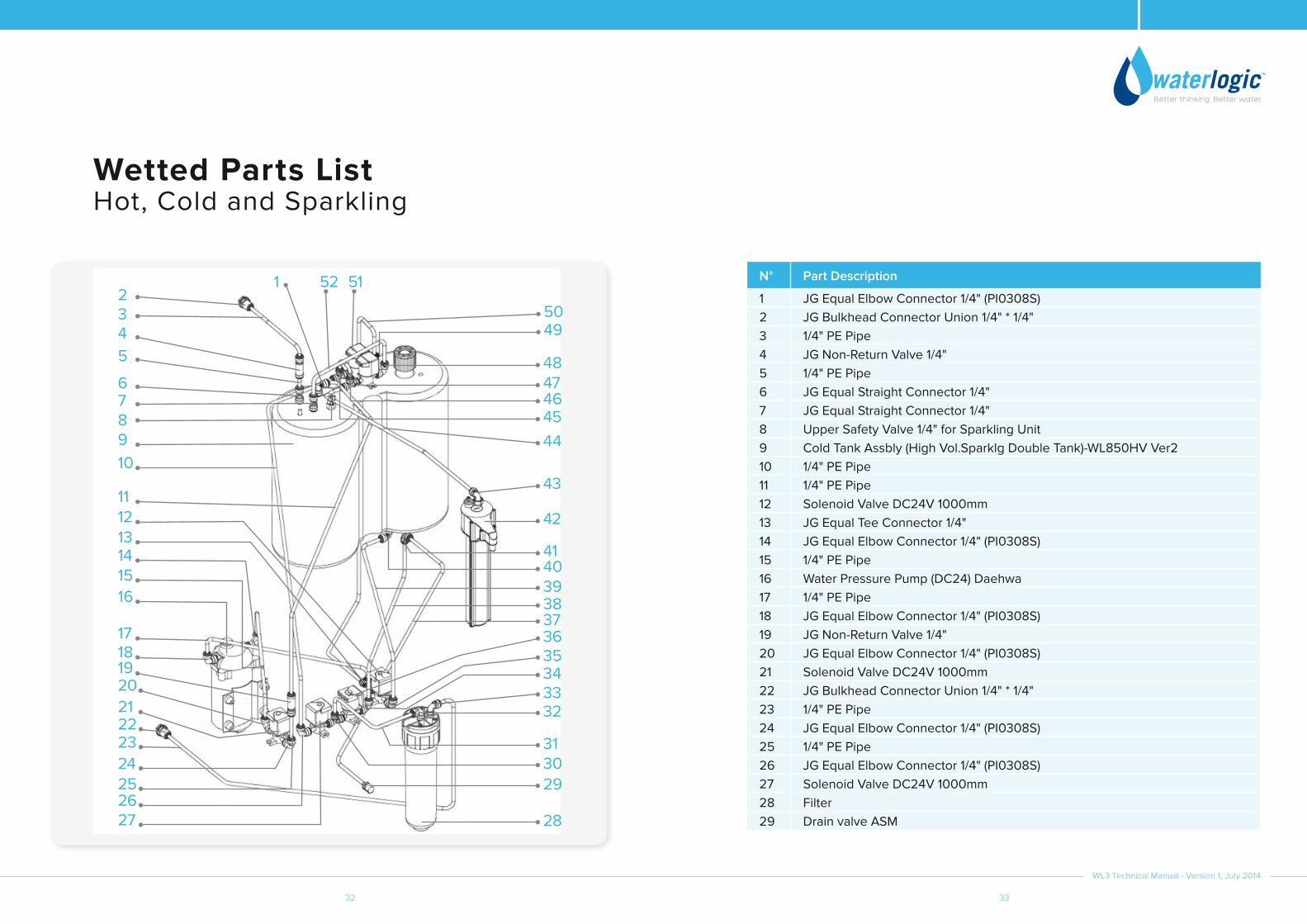
Wetted Parts ListHot, Cold and Sparkling
N° Part Description
1 JG Equal Elbow Connector 1/4" (PI0308S)2 JG Bulkhead Connector Union 1/4" * 1/4"3 1/4" PE Pipe4 JG Non-Return Valve 1/4"5 1/4" PE Pipe6 JG Equal Straight Connector 1/4"7 JG Equal Straight Connector 1/4"8 Upper Safety Valve 1/4" for Sparkling Unit9 Cold Tank Assbly (High Vol.Sparklg Double Tank)-WL850HV Ver210 1/4" PE Pipe11 1/4" PE Pipe12 Solenoid Valve DC24V 1000mm13 JG Equal Tee Connector 1/4"14 JG Equal Elbow Connector 1/4" (PI0308S)15 1/4" PE Pipe16 Water Pressure Pump (DC24) Daehwa17 1/4" PE Pipe18 JG Equal Elbow Connector 1/4" (PI0308S)19 JG Non-Return Valve 1/4"20 JG Equal Elbow Connector 1/4" (PI0308S)21 Solenoid Valve DC24V 1000mm22 JG Bulkhead Connector Union 1/4" * 1/4"23 1/4" PE Pipe24 JG Equal Elbow Connector 1/4" (PI0308S)25 1/4" PE Pipe26 JG Equal Elbow Connector 1/4" (PI0308S)27 Solenoid Valve DC24V 1000mm28 Filter29 Drain valve ASM
1314
16
17181920
2223
21
24252627
15
1211
109876
5432
1 52 51
5049
48
44
43
42
4140393837
28
29
3233343536
3031
474645

WL3 Technical Manual - Version 1, July 2014
34 35
Wetted Parts ListHot, Cold and Sparkling
N° Part Description
30 JG Equal Tee Connector 1/4"31 1/4" PE Pipe32 JG Equal Elbow Connector 1/4" (PI0308S)33 JG Equal Elbow Connector 1/4" (PI0308S)34 JG Equal Elbow Connector 1/4" (PI0308S)35 JG Equal Elbow Connector 1/4" (PI0308S)36 Solenoid Valve DC24V 1000mm37 1/4" PE Pipe38 1/4" PE Pipe39 1/4" PE Pipe40 JG Equal Elbow Connector 1/4" (PI0308S)41 JG Equal Tee Connector 1/4"42 FW Assm43 JG Equal Elbow Connector 1/4" (PI0308S)44 1/4" PE Pipe45 JG Equal Tee Connector 1/4"46 1/4" PE Pipe47 JG Equal Tee Connector 1/4"48 JG Equal Elbow Connector 1/4" (PI0308S)49 JG Equal Elbow Connector 1/4" (PI0308S)50 1/4" PE Pipe51 Double Solenoid valve (C&S) with wire harness assembled52 1/4" PE Pipe

WL3 Technical Manual - Version 1, July 2014
36 37
N° Part Description
1 WL3 Top Cover Black2 FS Back Panel for 850 Silver3 Switch - Heater/Compressor (Green)4 Power Switch(Red)-No back lights5 JG Bulkhead Connector Union 1/4" * 1/4"(PI1208S)6 Fuse Holder & Fuse 220V/10A with only one wire7 Gasket for Power Socket8 Socket for Plug Connection (Domestic PST-101SL)9 Thermostat10 WL950,650,750 Universal Left&Right Side panel Silver11 JG Bulkhead Connector Union 1/4" * 1/4"(PI1208S)12 Plastic Handle Silver13 Unit Control Rubber Feet WL300014 Compressor (R134a 1/8HP) 230V/50Hz thermally protected - LG15 Down Base White - WL650 universal as ST-801116 JG Equal Elbow Connector 1/4" (PI0308S)17 Solenoid Valve DC24V 1000mm18 JG Equal Elbow Connector 1/4" (PI0308S)19 JG Equal Elbow Connector 1/4" (PI0308S)20 Solenoid Valve DC24V 1000mm21 JG Equal Tee Connector 1/4"22 JG Equal Tee Connector 1/4"23 Solenoid Valve DC24V 1000mm24 JG Equal Elbow Connector 1/4" (PI0308S)25 Cushion for solenoid valve26 JG Equal Elbow Connector 1/4" (PI0308S)27 Solenoid Valve DC24V 1000mm28 JG Equal Elbow Connector 1/4" (PI0308S)29 Water Pressure Pump (DC24) Daehwa30 JG Equal Elbow Connector 1/4" (PI0308S)
Main Parts ListWL3 Mains Parts Illustration
1
23
61
5758
48
4749
46
37
3631
18
69
14
15
13
12
11
10
9
5
46
171628
29
30
8 7
3839
4041
5655 54
42
4344
44
32 35
3433
27 2625
24232221
2019
605962
68
535150 52
67
636465
66
38 39
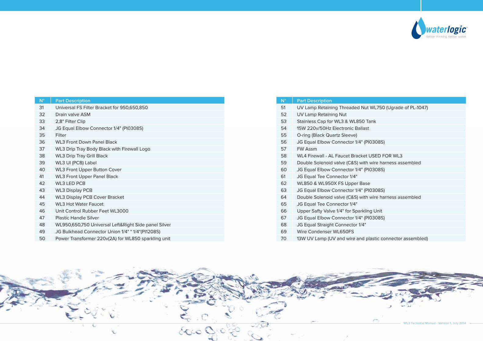
N° Part Description 51 UV Lamp Retaining Threaded Nut WL750 (Ugrade of PL-1047)52 UV Lamp Retaining Nut53 Stainless Cap for WL3 & WL850 Tank54 15W 220v/50Hz Electronic Ballast55 O-ring (Black Quartz Sleeve)56 JG Equal Elbow Connector 1/4" (PI0308S)57 FW Assm58 WL4 Firewall - AL Faucet Bracket USED FOR WL359 Double Solenoid valve (C&S) with wire harness assembled60 JG Equal Elbow Connector 1/4" (PI0308S)61 JG Equal Tee Connector 1/4"62 WL850 & WL950X FS Upper Base63 JG Equal Elbow Connector 1/4" (PI0308S)64 Double Solenoid valve (C&S) with wire harness assembled65 JG Equal Tee Connector 1/4"66 Upper Safty Valve 1/4" for Sparkling Unit67 JG Equal Elbow Connector 1/4" (PI0308S)68 JG Equal Straight Connector 1/4"69 Wire Condenser WL650FS70 13W UV Lamp (UV and wire and plastic connector assembled)
N° Part Description 31 Universal FS Filter Bracket for 950,650,85032 Drain valve ASM33 2,8" Filter Clip34 JG Equal Elbow Connector 1/4" (PI0308S)35 Filter 36 WL3 Front Down Panel Black37 WL3 Drip Tray Body Black with Firewall Logo38 WL3 Drip Tray Grill Black39 WL3 UI (PCB) Label40 WL3 Front Upper Button Cover41 WL3 Front Upper Panel Black42 WL3 LED PCB43 WL3 Display PCB44 WL3 Display PCB Cover Bracket45 WL3 Hot Water Faucet46 Unit Control Rubber Feet WL300047 Plastic Handle Silver48 WL950,650,750 Universal Left&Right Side panel Silver49 JG Bulkhead Connector Union 1/4" * 1/4"(PI1208S)50 Power Transformer 220v(2A) for WL850 sparkling unit
WL3 Technical Manual - Version 1, July 2014

40
EN
G02
53
-08
/08
/14
WLI Trading Ltd.Suite 4, 2nd Floor Beacon Court, Sandyford, Dublin 18, Ireland
www.waterlogic.com
Speak to a Water Expert Rest of the world
[email protected] + 353 1 293 1960
USA, Canada and Mexico
[email protected] + 1 402 884 7212
Waterlogic USA, 11710 Stonegate CircleOmaha, NE 68164