Embed Size (px)
Citation preview

WL-TR-96-3079
INVESTIGATION OF CONTROLLABILITY CRITERIA OF CLASS III AIRCRAFT EQUIPPED WITH A SIDESTICK
V. V. RODCHENKO, L. E. ZAICHIK, YU. P. YASHIN V. S. PEREBATOV, V. V. LYASNIKOV
TSAGI CENTRAL AEROHYDRODYNAMIC INSTITUTE ZHUKOVSKY-3, MOSCOW REGION, 140160 RUSSIA
DECEMBER 1994
FINAL REPORT
FLIGHT DYNAMICS DIRECTORATE WRIGHT LABORATORY AIR FORCE MATERIEL COMMAND WRIGHT-PATTERSON AIR FORCE BASE, OH 45433-7562
19961028100

NOTICE
When Government drawings, specifications, or other data are used for any purpose other than in connection with a definitely Government-related procurement, the United States Government incurs no reponsibility or any obligation whatsoever. The fact that the government may have formulated or in any way supplied the said drawings, specifications, or other data, is not to be regarded by implication, or otherwise in any manner construed, as licensing the holder, or any other person or corporation; or as conveying any rights or permission to manufacture, use, or sell any patented invention that may in any way be related thereot.
This report is releasable to the National Technical Information Service (NTIS). At NTIS, it will be available to the general public, including foreign nations.
This technical report has been reviewed and is approved for publication.
BRIAN K. STADLER DON R. GUM Project Engineer Chief, Control Integration and
Assessment Branch
DAVID P. LEMASTER Chief, Flight Control Division
If your address has changed, if you wish to be removed from our mailing list, or if the addressee is no longer employed by you organization please notify WL/FIGD-1, WPAFB, OH 45433-7505 to help us maintain a current mailing list.
Copies of this report should not be returned unless unless return is required by security considerations, contractural obligations, or notice on a specific document.

REPORT DOCUMENTATION PAGE Form Approved
OMB No. 0704-0188
Public reporting burden for this collection of information is estimated to average 1 hour per response, including the time for reviewing instructions, searching existing data sources gathering and maintaining the data needed, and completing and reviewing the collection of information. Send comments regarding this burden estimate or any other aspect of this collection of information, including suggestions for reducing this burden, to Washington Headquarters Services, Directorate for Information Operations and Reports 1215 Jefferson Davis Highway, Suite 1204, Arlington, VA 22202-4302, and to the Office of Management and Budget, Paperwork Reduction Project (0704-0188) Washington DC 20503
1. AGENCY USE ONLY (Leave blank) 2. REPORT DATE DEC 1994
3. REPORT TYPE AND DATES COVERED FINAL
4. TITLE AND SUBTITLE
Investigation of Controllability Criteria of Class III Aircraft Equipped with a sidestick
6. AUTHOR(S)
V.V. Rodchenko, L.E. Zaichik, Yu.P. Yashin V.S. Perebatov, V.V. Lyasnikov
7. PERFORMING ORGANIZATION NAME(S) AND ADDRESS(ES)
TsAGI Central Aerohydrodynamics Institute Zhükovsky - 3, Moscow Region, 140160 Russia
9. SPONSORING /MONITORING AGENCY NAME(S) AND ADDRESS(ES)
Flight Dynamics Directorate WL/FIGD Wright Laboratory Air Force Materiel Command Wright-Patterson AFB OH 45433-7562
5. FUNDING NUMBERS
PE: 62201F
8. PERFORMING ORGANIZATION REPORT NUMBER
SPC-93-4046
10. SPONSORING/MONITORING AGENCY REPORT NUMBER
WL-TR-96-3079
11. SUPPLEMENTARY NOTES
12a. DISTRIBUTION/AVAILABILITY STATEMENT Approved for Public Release; distribution is unlimited
12b. DISTRIBUTION CODE
13. ABSTRACT (Maximum 200 words) This work considers the controllability problems of Class III aircaft (large, heavy, low-to-medium maneuverability aircraft) equipped with sidestick controllers. This effort was done at TsAGI (Central Aerohydrodynamic Institute of Russia) in compli- ance with contract SPC-93-4046. The authors analyzed the existing data in the literature, conducted flight simulator investigations to generate new data, genera- lized the existing and new experimental data, conducted theoretical investigations, and compared these results with flight test data and data on specific aircraft.
This report contrasts the controllability of aircraft equipped with sidestick con- trollers and those equipped with conventional controllers. It describes the experi- mental technique used with the FS-102 flight simulator, presents the major character' istics of this simulator, and describes the sidestick controllers used in the exper- iments.
A theoretical approach determines the optimum values of sidestick loading and sensi- tivity characteristics. The controllability criteria to select these characteristics are justified based on this theoretical approach and obtained experimental data
11 duiuicr Tmi« The optimum values of .. sidestick loading and sensi-J-"- NUMBER OF PAGES tivity characteristics are calculated and compared with experi- mental data. SUBJECT TERMS; Sidestick, Loading Gradient, Design Large Aircraft Class
17. SECURITY CLASSIFICATION OF REPORT UNCLASS
Iil-X, Handling Qualities. Flving Qualities 18. SECURITY CLASSIFICATION
OF THIS PAGE UNCLASS
NSN 7540-01-280-5500
19. SECURITY CLASSIFICATION OF ABSTRACT UNCLASS
16. PRICE CODE
20. LIMITATION OF ABSTRACT
SAR
Standard Form 298 (Rev. 2-89) Prescribed by ANSI Std. Z39-18 298-102

FOREWORD
This work considers the controllability problems of Class III aircraft (large, heavy, low-to-medium maneuverability aircraft) equipped with sidestick controllers. This effort was done at TsAGI (Central Aerohydrodynamic Institute of Russia) in compliance with the contract SPC-93-4046. The authors analyzed the existing data in the literature, conducted flight simulator investigations to generate new data, generalized the existing and new experimental data, conducted theoretical investigations, and compared the results obtained in these investigations with the flight test data and the data on specific aircraft.
This report contrasts the controllability of aircraft equipped with sidestick controllers and those equipped with conventional controllers. It includes a description of the experimental technique used with the FS-102 flight simulator, presents the major characteristics of this simulator, and describes the sidestick controllers used in the experiments.
The report presents a theoretical approach to determine the optimum values of sidestick loading and sensitivity characteristics. The controllability criteria for selection of these characteristics are justified on the basis of this theoretical approach and the obtained experimental data. The optimum values of sidestick loading and sensitivity characteristics are calculated and compared with experimental data.

Table of Contents
FOREWORD i Table of Contents jjj Table of Figures iv Nomenclature vi 1. INTRODUCTION 1 2. EXPERIMENTAL CONDITIONS 2
2.1 Flight simulator 2 2.2 The sidestick controllers 2 2.3 Aircraft dynamics, flight regimes and varied parameters 4 2.4 Experimental approach 6
3. SIDESTICK AIRCRAFT CONTROLLABILITY FEATURES 6 3.1 Sidestick controllability versus conventional controllers 6 3.2 Sidestick ergonomics 9 3.3 Force trimming 11
4. THE THEORETICAL APPROACH TO CHOOSING THE OPTIMUM CONTROL SENSITIVITY AND LOADING CHARACTERISTICS OF A SIDE STICK 12
4.1 Properties of the pilot in the control loop and basic theses of approach 13 4.1.1 Preliminary remarks 13 4.1.2 The optimization principles of forces and displacements 14
4.2 Criteria of controllability 17 4.2.1 The criterion for choosing optimum lever loading characteristics 18 4.2.2 The criterion of optimum control sensitivity characteristics 20 4.2.3 Selection of criteria parameters 23
4.3 Recommendations for selecting the sidestick loading characteristics 24 4.3.1 Loading gradient 24 4.3.2 Breakout force 26 4.3.3 Loading Damping 27
4.4 Calculating the optimum values of control sensitivity characteristics of Class III aircraft equipped with a sidestick 28 4.5 A comparison of experimental and calculated results 30
5. CONCLUSIONS 33 6. FIGURES 35 7. REFERENCES 67
in

Table of Figures
Figure 2.1 Flight simulator FS -102 35 Figure 2.2 Computer generated image of runway 35 Figure 2.3 Sidestick RUS-D1 36 Figure 2.4 Constructive scheme of sidestick RUS-D1 37 Figure 2.5 Sidestick with electro-hydraulic loading system 38 Figure 2.6 Typical loading law and the range of the loading parameters reproduced by
theECLS 39 Figure 3.1 Piloting performance of a spacecraft at landing 40 Figure 3.2 Pilot rating depending upon longitudinal short period frequency 41 Figure 3.3 Pitch stabilization error of the aircraft with the centerstick and sidestick and
pilot rating of the aircraft with the side stick and wheel in dependency of the longitudinal short period movement damping 42
Figure 3.4 Lever type influencing on dynamic properties of pilot 43 Figure 3.5 A Comparison of roll stabilization accuracy while handling the wheel,
sidestick and centerstick 43 Figure 3.6 A comparison of yaw stabilization accuracy while handling with the sidestick
and pedals 44 Figure 3.7 A comparison of roll and yaw stabilization accuracy while handling with the
sidestick and pedals 44 Figure 3.8 A comparison of roll and yaw stabilization accuracy while handling with the
sidestick and pedals during landing approach 45 Figure 3.9 Left hand piloting accuracy of right handed pilots 45 Figure 3.10 Sidesticks with uncrossing axes 46 Figure 3.11 The loading characteristics of A-320 sidestick 47 Figure 3.12 Pilot rating of different methods of two sidestick interactions (Ref. 16) 47 Figure 3.13 Manual electrical force trimming of a sidestick 48 Figure 3.14 Semi-automatic electrical force trimming of a sidestick 48 Figure 3.15 Scheme of a "fast" force trimming of a sidestick 48 Figure 4.1 Aspects influencing the aircraft lever loading 49 Figure 4.2 Static characteristics of lever loading 49 Figure 4.5 Pilot ratings regions in plane of the control sensitivity characteristics of
sidestick aircraft 50 Figure 4.4 Longitudinal control sensitivity and sidestick loading characteristics
influencing the pilot ratings 51 Figure 4.4 (CONTINUATION) 52 Figure 4.5 Lateral control sensitivity and sidestick loading influencing pilot ratings 53 Figure 4.6 Deflections of control lever at estimating the control sensitivity 54 Figure 4.7 Spectral density of presented lever deflections 54 Figure 4.8 Pilot ratings worsening at deviation of control sensitivity characteristics 55 Figure 4.9 Graphic of Minimum 56 Figure 4.10 Dependence of pitch stabilization error dispersion on control sensitivity
(Ref. 11) 56 Figure 4.11 Aircraft amplitude-frequency characteristics at optimum control sensitivity57 Figure 4.12 Dependencies of the total gain coefficient kKand cut-off frequency of "pilot-
aircraft" system on control sensitivity 57
IV

Figure 4.13 Optimal values of the sidestick gradient 58 Figure 4.14 Influence of the sidestick loading gradient on pilot rating 58 Figure 4.15 Influence of the lateral control sensitivity and breakout on pilot ratings 59 Figure 4.16 Influence of the breakout on pilot ratings : 59 Figure 4.17 Influence of the loading gradient on the sidestick breakout force optimum
values 60 Figure 4.18 Influence of the breakout force on the aircraft control sensitivity 60 Figure 4.19 Influence of the sidestick damping on the pitch stabilization accuracy 61 Figure 4.20 Influence of the sidestick damping on pilot ratings 62 Figure 4.21 Dependence of parameter Aon sidestick loading gradient 63 Figure 4.22 Dependence of parameter >4ron sidestick loading gradient 63
Figure 4.23 Influence of the longitudinal short-period motion frequency CO on the
optimum Fn values 64
Figure 4.24 Influence of the longitudinal short-period motion damping gs on the
optimum Fn values 64
Figure 4.25 Dependence of the optimum F values fromHz parameter 65
Figure 4.26 Dependence of the optimum Fn values from time delay 66
Figure 4.27 Dependence of the optimumP*value from roll time constant^ 66
v

Nomenclature
F - stick force (kg)
x F - stick feel gradient (kg/mm)
x F - stick feel damping gradient (kg/mm/sec)
Fo - stick breakout force (kg) Ffr - stick coulomb friction force (kg) Fn - longitudinal stick force per unit normal acceleration (kg/g, mm/g)
Fp - lateral stick force per unit roll rate (kg/deg/sec, mm/deg/sec) g - gravitational acceleration (m/sec2) H - flight altitude (m) K - gain coefficient of transmission L5 - non-dimensional rolling moment per unit aileron deflection
M5 - non-dimensional pitching moment per unit elevator deflection
m - stick inertia (kgm) Lx - non-dimensional yawing moment per unit rudder deflection
nz - normal acceleration (g) n - normal acceleration per unit angle of attack (g/rad)
z«
ny - lateral acceleration per unit sideslip angle (g/rad)
p - roll rate (rad/sec) q - pitch rate (rad/sec) V - flight velocity (km/hour) X - stick displacement (mm) Xn - longitudinal stick displacement per unit normal acceleration (kg/g, mm/g)
Xp - lateral stick displacement per unit roll rate (kg/deg/sec, mm/deg/sec) X - flight distance (m) Y - aircraft side displacement (m) xa - lateral stick displacement (used in aircraft dynamic equations only) xe - longitudinal stick displacement (used in aircraft dynamic equations only) xr - rudder pedal displacements (used in aircraft dynamic equations only)
a - angle of attack (rad) (Xw - angle of attack caused by wind disturbances (rad)
ß - sideslip angle (rad) ßw - sideslip angle caused by wind disturbances (rad)
VI

r flightpath angle (rad)
fr - dutch roll damping ratio
~>sp short-period damping ratio
e pitch angle (rad)
0 - bank angle (rad)
Ta equivalent aileron time delay (sec)
Te equivalent elevator time delay (sec) Tr equivalent rudder time delay (sec)
?R roll mode time constant (sec)
¥ - yaw angle (rad) cor dutch roll frequency (rad/sec)
COsp - short-period frequency (rad/sec)
VII

1. INTRODUCTION
Controllability criteria have always received considerable attention, since they have an essential effect on aircraft handling qualities, mission effectiveness, and flight safety. These criteria continue to develop concurrently with advances in aviation. Today's aircraft, with highly augmented manual control loops, require development of generalized criteria. These criteria provide estimates of controllability for different piloting tasks and different aircraft, including those with unconventional dynamic characteristics and controllers [1 - 9].
At present, the most developed controllability criteria are those for estimation of required aircraft dynamic characteristics. The criteria for estimation of optimum values of control lever loading and sensitivity characteristics are somewhat less developed. These characteristics not only depend in a complicated way one on another, but also on flight regime, aircraft dynamic characteristics, and control lever type. There is no sufficiently general criterion for estimating control lever loading and optimum control sensitivity characteristics in the literature. This consideration not only hampers optimization of these characteristics when designing an aircraft, but it also essentially restrains the controllability theory as a whole. Development of such criteria has become especially important for aircraft equipped with unconventional controllers (sidestick, miniwheel).
One of the main goals of this report is further development of the theoretical approach, proposed earlier [7,8,9,11], to the optimization of controllability criteria for control lever loading and control sensitivity characteristics. This approach takes into account their mutual dependence on aircraft dynamic characteristics and flight regimes. Another goal of this report is the specification of these criteria for Class III aircraft with sidestick controllers and analysis of controllability features of these aircraft.
The feasibility of the sidestick controller in fly-by-wire aircraft has been proven already. At present it is being used on several different aircraft: for instance the F-16, Rafale, and YF-22 fighters, the Space Shuttle reentry vehicles, and the A-320 and A-340 airliners.
Sidestick controllers have a number of advantages in comparison with conventional control levers: 1) they take less space, 2) they improve the pilot's view of the instrument panel, 3) they weigh less, 4) they make it more comfortable for the pilot, in particular for entering and exiting the cockpit, plus some other advantages. These sidestick properties are evident and well known. However, the optimization of handling qualities and controllability characteristics for aircraft equipped with sidesticks is more obscure. The lack of sidestick-equipped aircraft design experience and the limited amount of documentation require that the available data be systematized and investigations in this area be conducted.
In order to solve the formulated problems, in the present report the authors analyzed the literature data, conducted flight simulator experiments, performed a generalization

of the available and obtained data, carried out theoretical investigations, and compared the obtained data with flight test results and the data on specific aircraft.
The experimental investigations of sidestick-equipped Class III aircraft controllability were carried out mainly on TsAGI's FS-102 ground-based simulator. The experimental results were compared with the data available and with results obtained on the TU-154M flying laboratory with the authors' participation.
2. EXPERIMENTAL CONDITIONS
2A Flight simulator The majority of experiments were carried out on TsAGI's FS-102 flight simulator
(Fig. 2.1). This facility is designed to study stability and controllability of Class III aircraft. Its characteristics are:
Pilot cockpit:
Two seats and regular instrumentation corresponding to Class III aircraft.
Control levers:
Variable (centerstick, wheel, sidestick, pedals), with an electro-hydraulic loading system.
Visual system:
One color channel with optical collimator and analog-digital synthesis of a runway and Earth surface (Fig. 2.2).
Cockpit motion system:
Six-degree-of-freedom, synergetic type with an actuator stroke of 1.8 m; maximum displacements in heave of ±1.2 m; in longitudinal and lateral directions, ±1.5 m; in roll, ±30 deg; in pitch, ±40 deg; in yaw, ±60 deg.
2.2 The sidestick controllers In the experiments we used two types of sidestick controllers. One of them was the
RUS-D1 sidestick with a hydraulic damper and changeable load springs. The choice of this sidestick was conditioned by the fact that it was used in the in-flight experiments on the Tu-154M flight simulator. Its use allowed us to make a more meaningful comparison between the ground simulator test data and the in-flight data.
The RUS-D1 three-degree-of-freedom sidestick (Fig. 2.3) provides forces necessary for control and electric signal generation in pitch, yaw, and roll. This sidestick has displacement transducers in all control channels. There are also force transducers in pitch and roll which provide control signals proportional to both stick displacement and force.
Figure 2.4 shows the sidestick constructive layout. The control stick includes: a grip (1) which moves via a 3-DOF cardan unit (3) inside the case; pitch, roll and yaw spring

loaders (29, 34, 39); reserved displacement transducers in pitch (31-33), roll (35-37) and yaw (40-42); a 2-DOF force transducer (9); and hydraulic dampers in pitch (30) and roll (35). Each damper has adjustment bolts to vary damping coefficient. The stick is equipped with additional loaders set with variable stiffness via changeable springs. The spring design allows variation of breakout force as well as load gradient.
Main technical characteristics of the RUS-D1 sidestick:
1. Maximum deflections in pitch, roll, and yaw are ±20° with smooth limitation adjustment within the whole range.
2. The stick moment arms (the distance between the center of the grip and the axis of rotation) in pitch and roll are 120 mm.
3. The maximum forces on the stick (set by the springs and measured at its center)
in pitch and roll: 2-12 kg;
in yaw: 0.08 - 0.30 kg.
4. The breakout forces, F„
in pitch and roll: 0 -1 kg;
in yaw: 0.01 - 0.04 kg.
5. Friction, measured at the stick center, does not exceed
in pitch and roll: 0.2 kg;
in yaw: 0.005 kg.
6. Load damping coefficients in pitch and roll vary within the range 0 - 0.01 kg/mm/s.
7. The displacement transducers (three times reserved) are of induction type, with a voltage supply of -36 volt at 400 Hz.
8. The force transducers in pitch and roll are four times reserved.
9. Dimensions : 80x80x365 mm.
10. Weight does not exceed 2.9 kg.
The RUS-D1 sidestick was developed jointly by NIIAO and TsAGI. It was widely used in ground-based simulation experiments at TsAGI and in-flight experiments on the Ka-32 helicoper and the TU-154M in-flight simulator. It has gained a good reputation as a universal research instrument. In this work it was used in its 2-DOF option to study the influence of sidesticks on aircraft controllability.
The other sidestick used in the ground simulator tests had a universal electro-hydraulic loading system which allowed it to reproduce practically any desired loading variation. Figure 2.5 shows a picture of this sidestick. This sidestick was developed at TsAGI. It consists of: a grip (1); force transducers in pitch and roll (2); a 2-DOF cardan unit (3); electro-hydraulic loading drives (4 and 5); pitch and roll displacement transducers (6

and 7); and a control unit to compute the loading laws. Typical loading characteristics and the range of loading parameters for both channels are given in Figure 2.6.
2.3 Aircraft dynamics, flight regimes and varied parameters Usually, when studying general problems of aircraft controllability, e.g. in the case of MIL-F-8785, aircraft motion equations are considered linearized with respect to horizontal flight with a constant velocity. Such equations were used in the present effort as it was intended to be generic research. In the investigations the authors considered generalized stability and controllability characteristics (fi) ,£,...). Consequently, the
equations of motion were expressed via these characteristics. These equations can be represented in the following form (the phugoid component was neglected):
cc =—n (cc + cc ) + q
(
8
co2 +—n \—n +2c co
\
(« + aj-
n +2c co g + K Mxx(t-r) Y za ~SP SP P- e Sc e\ e)
6 = q; y = 6-a\
H = V=Vy;
X=V
ß + 2grCOrß + co:ß = KNsXXt-^) + ^nJw-(D2rßw
$ = p
r ^ V yß V
Y=v0(-ß+yf)
(2.1)
where Ke, Ka, Kr are the pitch, roll and yaw gain coefficients of a transmission; the
terms KeM5xe,KrMöxr,KaMgxa are the initial pitch, yaw, and roll rates per unit
displacement of a corresponding control lever (sidestick, pedal); the increments of

angles of attack, pitch, flight path, altitude, etc, are given with respect to their initial values a=a0, 60 -a0,jo= 0, ß0=^0=^0 = o, H=H0; aw, ßw are the angles of attack and sideslip caused by the wind disturbances; xe, rr, xa are the equivalent time delays in the pitch, yaw and roll control loops, approximated by the first term of the Pade series expansion:
e-= 2.
2
Three flight conditions were simulated: landing approach (7=260 km/h), cruise flight (//=11 km, M=0.8) and a level turn (#=400 m, V=400 km/h). The following aircraft characteristics were varied in the experiments:
• dynamic characteristics of longitudinal and lateral motion
- natural frequency, (Osp, and damping ratio, gsp, of the longitudinal short
periodic motion;
- change in steady-state normal acceleration per unit change in angle of attack for an incremental pitch control deflection at constant speed, n ;
- pitch, T,, and roll, 1a , control system time delays;
- isolated roll mode time constant TR.
• the longitudinal and lateral aircraft control sensitivity characteristics X ,F ,X ,F .
• the sidestick loading characteristics in the longitudinal and lateral control channels
- loading gradients F*, Fax;
- breakout forces F0 , F0 ;
- damping coefficients Fex, Fa
x.
The directional dynamic characteristics were held constant. The directional characteristic coefficients in the equations of motion (1) were taken to be :
Kr ■ N5r = -8 /m,; cor = 1.64 s~l; gr = 0.3; Fr' = 0.4 Ymm; Lp = -6Al s~2.

Variation of the derivatives Xn and X (and hence of Fn and Fp) was accomplished
by variation of the transmission coefficients from the control lever to the longitudinal and lateral controls, Ke and Ka.
2.4 Experimental approach
A comparative study of the influence of sidestick and conventional controllers (a centerstick and a wheel) on aircraft controllability was conducted in order to reveal the peculiarities of sidestick controllability.
Three pilots took part in the experiments. One of them, a test pilot, participated both in the ground simulator and the flight experiments on the TU-154M flying laboratory. The other two, both ex-pilots, were skilled and experienced in flight simulation experiments on various programs. Additionally, pilot-operators took part in certain experiments. The pilots had to perform maneuvers typical for a Class III aircraft.
After each flight the pilots remarked on the piloting features and handling characteristics using a Cooper-Harper type scale. For certain experiments with a huge data flow, the obtained handling estimates were processed according to a special technique previously developed at TsAGI, in order to obtain the outcome estimation [11]. For the analysis of the experimental results, the motion parameter variations were recorded and the handling precision was estimated. In certain experiments, quantitative data on pilot inputs were determined such as spectral density, RMS piloting errors and pilot frequency characteristics.
3. SIDESTICK AIRCRAFT CONTROLLABILITY FEATURES
3.1 Sidestick controilabiiity versus conventional controllers As previously noted, there is no doubt about the feasibility of sidesticks for aircraft control. However, due to the lack of experience in their use, the perceived differences in aircraft controllability between sidestick-equipped aircraft and those equipped with other controllers has limited the use of sidesticks in aircraft. The following paragraphs consider these differences for each control channel.
The available literature [13, 14, 15] shows that sidesticks can provide piloting characteristics and control precision in the longitudinal channel no worse than that of conventional controllers. Also, an overwhelming majority of pilots prefer sidesticks. At the same time there has been no final decision on the differences in aircraft controllability between sidesticks and conventional controllers. The investigations carried out in the present work show that handling qualities with a sidestick are better in the longitudinal control channel, and somewhat worse in the lateral control channel compared with centersticks and control wheels.
Figures 3.1 through 3.3 show data for the longitudinal control channel. Figure 3.1 shows time histories of an aerospace vehicle during landing (performed on the FS-102 ground

Simulator) using both a sidestick and a centerstick. The sidestick permits smoother control of the vertical velocity Vz as well as smaller oscillations in normal acceleration and angle of attack while flaring.
Figures 3.2 and 3.3 compare pilot ratings as functions of the static stability and damping coefficient of the longitudinal short-period motion for a Class III airplane equipped with a wheel and with a sidestick. The experimental data show that the sidestick is preferable to conventional controllers for small stability margin and low damping.
This handling qualities improvement can be explained with the help of experimental identification of pilot dynamic characteristics during pitch stabilization (Fig. 3.4). The pilot control lag x decreases with the sidestick. This can be accounted for by a lower time delay in the sidestick and the higher dynamic properties of the muscles involved in use of the sidestick. As a result, the overall pilot reaction time improves, and his gain coefficient and the open-loop "aircraft-pilot" system stability margin grows. This enables the pilot to provide "aircraft-pilot" system stability at lower aircraft stability margins and lower aircraft damping. This conclusion was supported by the experiments.
The peculiarities of the sidestick-equipped Class III aircraft lateral controllability were estimated by comparative analysis with centerstick and wheel control test results (Fig.3.5). The data show that the sidestick provides worse control precision than the wheel for both good (xÄ=1 s) and bad (xfi=10 s) roll dynamic characteristics. Evidently, the differences in the "arm-control lever" system dynamics between the wheel and the sidestick are not as significant in the lateral channel as in longitudinal channel. Second, pilots can more accurately modulate the roll control forces with the wheel (using both arms) than with the sidestick. It should be noted that the pilots induced higher roll oscillations with the sidestick, especially when it had no damper.
As far as the centerstick is concerned, the data show that the sidestick provides better precision for poor aircraft dynamic characteristics. This is probably accounted for by the higher time delay with the centerstick.
For both longitudinal and lateral control channels, pilots noticed a greater incidence of pilot overcontrol in emergency situations and more coupling between longitudinal and lateral axes. Even in normal piloting situations, there was interference caused by the sidestick controls; intense control in the longitudinal channel caused inadvertent roll disturbances. These sidestick drawbacks may become dangerous in emergency situations when pilots operate aggressively. The conventional controllers seem more appropriate in emergency situations because they require higher forces and displacements and involve different muscles and sensors. These advantages provide the pilot with distinct kinesthetic feedback on his controller actions. These problems with sidestick controllers should receive further attention.
With fly-by-wire aircraft, it is necessary to consider the possibility and effectiveness of directional control via a sidestick. There are no data on course control via a sidestick in the literature. Therefore, the authors conducted a number of experiments aimed at assessing aircraft handling qualities in the directional channel using a sidestick. In these
7

experiments the sidestick had a third degree of freedom for directional control in addition to the roll and pitch channels.
For one-channel sidestick course control, the data in Figure 3.6 show considerably higher control precision (by 10-40%) with the sidestick than with the rudder pedals. Evidently, this can be attributed to considerably lower pilot lag with the sidestick than with the rudder pedals (i.e. the sidestick dynamics are clearly superior to those of the pedals). However, the isolated yaw control problem is rare in practice and is more interesting in a methodological sense. Therefore, the sidestick-aided directional control effectiveness was assessed for the problems of full lateral motion control, e.g. when refueling.
In an experiment on two-channel roll control, the pilots first controlled the aircraft using the sidestick alone, and then using the sidestick in roll and the rudder pedals directionally. The results of this experiment are shown in Figure 3.7. The sidestick still has an advantage in this scenario. Note that there is a 5-20% degradation in roll precision for the sidestick alone. This may be attributable to the complexity of the pilot's roll control motion when combined with the directional control in the same lever. This can play a negative role in other piloting tasks as well, for example in approach and landing, where high roll precision is required.
Three-channel control of the full aircraft motion using a 3-DOF sidestick (pitch, roll and yaw) was investigated for the approach task. The experimental results are shown in Figure 3.8. This figure shows that three-channel control using a 3-DOF sidestick is possible, but is inferior for directional and roll control in comparison to using the sidestick for roll and pitch control and the rudder pedals for directional control.
According to pilot comments, control with a three-channel sidestick creates an information overload and requires additional hand manipulations in the third channel. As a result, the pilot is forced to work consciously rather than subconsciously, which makes generation of control actions more difficult. It may also manifest itself in difficulties in controlling the aircraft in emergency situations.
Piloting comfort, accuracy, and reliability determine the expediency of sidestick application in directional control. For one-channel directional control there was no inconvenience. The sidestick may be more effective and expedient than rudder pedals for some special tracking tasks. However, pilots have considerable difficulty with combined roll and yaw control in conditions of asymmetric arm operation. Simultaneous left roll command and right yaw command is especially difficult. This two-motion combination is rather complicated and pilots have to think it over, which is not necessary in the case of yaw control by means of rudder pedals. Thus, the expediency of neglecting pedals for yaw control in favour of a third degree of freedom in the sidestick for Class III airplanes seems doubtful. It causes a loss of precision (particularly in roll), complicates the control process, and entails inconvenience in the piloting operation.
The problem of left-hand controllability arises for Class III aircraft equipped with a right sidestick for the right pilot and a left sidestick for the left pilot. Statistics show that 10% of the population are left-handed, 60% are right-handed, and 30% are ambidextrous.
8

The possibility of left-handed control in normal flight conditions is already confirmed in practice by utilization of the left-hand sidestick on the A-320 airliner. Nevertheless, a valid question is how much left-handed control differs from right-handed control, as well as how accurate and reliable left-hand control proves to be in emergency situations.
The authors carried out special simulation experiments to determine control precision and maximum permissible dynamic characteristics of the controlled object using both right-hand and left-hand control. Figure 3.9 shows the results of these experiments. These experiments showed that skilled pilots (who always have some experience in left-hand control) usually achieved the required accuracy of control with the left sidestick after 2-3 training flights, though accuracy was somewhat less than with the right sidestick. Operators, skilled in right-hand control but inexperienced in left-hand control, quickly gained the skills. After 2-3 days of training the operators had managed the task. However, precision with the left hand was considerably lower than with the right hand. This reduction in precision may well impair flight safety, especially in adverse flight conditions and failure situations. That is why we recommend avoiding a cockpit arrangement with a standard sidestick on the left of the pilot.
An emergency situation in which the pilot has to handle a right sidestick with his left hand may occur. Experiments have shown that control is possible in this situation but with degraded handling qualitites. For this purpose a reserve left sidestick is advisable.
3.2 Sidestick ergonomics From the above results it follows that during design of control systems which utilize a sidestick, one should pay attention to problems associated with the ergonomic peculiarities of sidesticks. This section considers some of these problems.
For sidesticks of the "lever" type such as those used in the A-320 and A-340 and investigated in this work, there is a coupling between pitch and roll inputs. It arises because the rotation axes of the stick are misaligned with the rotation axes of the pilot's arm. The same arm links produce both pitch and roll control forces, thus causing difficulties when attempting to regulate control forces in each axis. This drawback exists for conventional centersticks as well. The wheel lacks this drawback because its pitch and roll rotation axes are kinematically seperated and control forces are seperated accordingly. For the wheel, one muscle group generates roll motion while the forearm displacement generates pitch motion.
This coupling is particularly characteristic of the roll channel, especially when there are balancing forces in the pitch channel. When flying fast, maneuverable airplanes, pilots easily notice and correct the involuntary roll component. For less maneuverable airplanes this roll deflection presents a danger, especially during landing and take-off, because pilots notice and eliminate it much more slowly. That is why it is necessary to take actions to minimize this drawback.
One of these actions is to construct the sidestick such that it provides "physiological separation" of the control forces, e.g. by means of divided pitch and roll rotation axes. Figure 3.10 shows two possible options of this sidestick construction. In the first case

the pitch-rotation axis is located below the stick handle and the roll-rotation axis is at the middle of the stick arm and directed along the forearm. In the second case (the so- called "lock-type" sidestick) the advance control motion in the pitch channel is put into effect together with the elbow-rest. There is no information about the advantages of this option in the literature. However, a moving elbow-rest may cause a loss of precision because of the lack of tactile information on arm displacement. In the case of the fixed elbow-rest the tactile information considerably increases the motion precision. That is why the first option is more preferable.
Another type of sidestick with "physiological separation" of pitch and roll is a hand-type sidestick, where the axes of rotation cross either in the center of the hand or in the wrist. This one conforms to the physiology of the human arm best of all, because in this case different groups of muscles provide precise control forces in each channel. Pilots appreciated this type of sidestick, but due to the sophisticated construction, manufacture, and maintenance technology it was not put into production. At present an original construction of the hand-type sidestick has been developed. This sidestick mechanization requires more detailed study.
One of the major problems when developing a control system with a sidestick is the number and type of control effort components realized by the sidestick. Though at present there are sidesticks with three or more components, the overwhelming majority of sidesticks have two components: pitch and roll. Types of components include both moving sidesticks with displacement signals (A-320) and fixed sidesticks with force signals (F-16). Sometimes the latter sidesticks are used with the moving option on an elastic (spring or rubber) foundation.
The sidestick displacement range and loading are the most important characteristics that determine the sidestick construction and influence the controllability characteristics of the control system as a whole. Hand mobility determines the range of sidestick maximum deflections. For pitch control, performed by turning the hand in the plane of the palm, the advisable stick deflection angle is ±20°. The advance displacement range is determined via the stick arm. Taking into account the limited arm dimensions the stick arm is expected to be rather small. Thus, if a sidestick has a deflection angle of ± 20° and the stick arm (measured through the lever center) is 120 mm, then the stick total displacement is ±40 mm (the A-320 has ±35 mm total displacement at a deflection angle of ±16°). For roll control, performed by rotating the arm with respect to the forearm axis, much more stick deflection angle is permissible, but due to space limitations it is usually restricted to 20°-30°. As far as loading is concerned, there is a certain control lever force/displacement relation. This relation is complex, depending on the control lever type and various design factors. Figure 3.11 gives the sidestick longitudinal and lateral loading characteristics for the A-320. One can see that roll loading is asymmetric in order to balance human "asymmetry" in perceiving forces applied to the sidestick to the right or to the left. The problem of loading characteristics has been studied in detail in the present work and will be discussed in more detail below. As will be shown below, the loading characteristics chosen for the A-320 conform to the results of the authors' investigation.
10

From an ergonomic standpoint, pilots prefer sidesticks over conventional control levers. A sidestick with properly fixed elbow-rest provides a more comfortable working position than centersticks and wheels. At present a grip similar to the centerstick is common, but the sidestick grip has a greater top rake. These sidesticks are traditional, tested in flight on many types of airplanes, and are not unacceptable to pilots. There is some experience in using sidesticks with a grip enfolded by the hand. This grip seems to conform to the arm physiology to a greater degree. However, this changes the arrangement of additional controls on the grip, and hence, the way pilots use it. Thus this type of sidestick is not widely used. Research to optimize the grip shape in order to find the most comfortable design and provide better precision should be continued.
Sidestick dimensions determine its location in the cockpit, for example, in the "Buran" cockpit (the dimensions are measured with respect to the lever center):
- the distance from the seat longitudinal plane is 280 mm
- the seat height with respect to the S-point is 280 mm
- the distance from the S-point along the longitudinal axis is 320±40 mm
- lever setting angle in the longitudinal plane is 30°-40°
- the sidestick roll setting angle is 12°-18°
Two-pilot aircraft with sidesticks mechanically independent of each other have the problem of simultaneous or conflicting control inputs. On the A-320, the two-pilot interaction problem is solved by processing signals from the left and right sidesticks. Reference 16 reports on investigations on other techniques to solve the pilot interaction problem, including a mechanical link between sidesticks. The results of the investigation are shown in Figure 3.12 as pilots ratings versus link option. These results show that at present there are no sidestick link options superior to the mechanical link, but work in this direction should be continued.
Thus, a sidestick for Class III aircraft is in some aspects better and in other aspects worse than a wheel. Therefore, the suitability of the sidestick must be determined in each case considering the specific conditions.
3.3 Force trimming Control system generation is known to be essentially dependent on the selection of the trimming forces type. According to the pilots opinion, for the effective utilization of the sidestick, it is expedient to provide the possibility of the manual effort trimming in the horizontal flight. As it is known, the A-320 employs the automatic effort trimming, but the manual trimming necessity may well arise in case of the zero transducer data output.
Trimming mechanisms such as those used on a centerstick (i.e. with variation of the neutral stick position) complicate the sidestick design and increase its space requirements. Also, due to the small displacements involved, this type of mechanization does not provide the pilot with essential information. Another trimming mechanization, the so-called electric trim, is preferable. In this mechanization (Fig. 3.13), the command signal to the control system is the sum of the trim signal and the
11

pilot input to the sidestick. When the pilot engages the trim switch, the trim signal increases so as to maintain a constant command signal while the pilot reduces his forces on the stick. The drawback of electric trimming is the fact that it causes unavoidable motion transients because it is difficult for the pilot to estimate and match the rate of change of the trim signal. The higher the trim rate, the greater the motion transients become. Thus, the trim rate should be low in order to diminish the motion transients. On the other hand, the trim rate should not be too low, for the trimming process should not take too long.
There are several different schemes to simplify trim system mechanization of the sidestick. For instance, one can design a relatively simple semi-automatic trimming mechanization. This mechanization is initiated simply by pressing a two-position button (Fig. 3.14). The trimming direction is selected automatically, according to the sign of the signal coming from the sidestick. Here the trim rate may be either constant or variable (proportional to the sidestick output signal). Such a trim system was worked out on in-flight simulator experiments, but several questions remain. For example, two buttons are needed for separate trimming in pitch and roll, which is very inconvenient. Furthermore, it does not eliminate the drawbacks noted earlier.
At present, TsAGI has developed a trim mechanization which allows the pilot to trim out the forces practically instantaneously without any motion transients [17]. Figure 3.15 shows a block diagram and time histories of this mechanization.
4. THE THEORETICAL APPROACH TO CHOOSING THE OPTIMUM CONTROL SENSITIVITY AND LOADING CHARACTERISTICS OF A SIDE STICK
In practice it is not easy to choose the optimum values of control sensitivity and lever loading characteristics since they depend not only upon each other, but also upon class of aircraft, type of control lever, piloting task, and aircraft dynamic characteristics. Furthermore, the characteristics of lever loading and control sensitivity have a definite effect on aircraft controllability and flight safety. Therefore, the development of methods to optimize the characteristics of lever loading and control sensitivity is a problem of great practical importance. The lack of such methods restricts the development of manual control optimization theory as a whole.
At present there is no sufficiently general theory or technique of calculation for selecting the optimum characteristics of control sensitivity and loading for sidesticks, or for other control levers. In various Aviation Standards there are maximum admissible limits on some parameters to address safety of flight considerations. The optimum values of lever loading and control sensitivity characteristics are chosen experimentally, with due regard for prior experience with aircraft close to each other in class and purpose [1-5]. In the past, when aircraft dynamic characteristics (i.e., classical dynamics) and aircraft control levers (wheel for transport aircraft, centerstick for fighters, and rudder pedals) were practically uniform, the lever loading and sensitivity could roughly be chosen on the basis of those of the previous generation. Further refinements could then be made
12

in flight test. This approach has become inadequate in recent years due to 1) the incorporation of automatic augmentation in the manual control loop, 2) the appearance of non-classical dynamic characteristics, 3) new control levers (including the sidestick), and 4) the expansion of aircraft flight envelopes [2,3]. In order to choose the characteristics of the aircraft at the earliest stages of its design, and also to narrow the scope of characteristics to be considered during the follow-on experiments, it has become necessary to develop theoretical methods to optimize lever loading and sensitivity characteristics.
For traditional control levers, the maximum admissible forces and displacements to perform maneuvers with large accelerations or to counteract failures and strong gusts are presented in literature and specifications [4,5]. For new control levers these admissible values may be sufficiently easy to estimate by considering the physiological limits of the pilot [6]. The problem of selecting optimum lever loading and control sensitivity characteristics for continuous tracking, when the pilot has to perform small but exact actions with the control levers, is more complicated and less understood. Solution of this problem is usually crucial to choosing the characteristics of lever loading and control sensitivity and causes great difficulties in practice.
The chief objective of this section of the report is to develop the theoretical approach for choosing the optimum control sensitivity and sidestick loading characteristics for the stabilization task based on dynamic performance characteristics. The idea behind this approach was first proposed in Reference 8. The present report is a summation and further development of this approach as applied to a sidestick.
4.1 Properties of the pilot in the control loop and basic theses of approach
4.1.1 Preliminary remarks
Generally speaking, taking into account the dynamic characteristics of the linkage, lever loading can be described by complicated differential equations with a great number of parameters. The form of the equations and the number of parameters are dependent on the type of control system (with or without boosters, fly-by-wire system or mechanical linkage) and its specific characteristics (Fig. 4.1). When lever displacements X and applied forces F are around neutral and the trim lever position is small, the optimal lever loading for the stabilization task may be described by the loading gradient Fx, breakout force F0, coulomb friction force Ffn mass m, and
coefficient of loading damping Fx. This is the type of loading considered here and is described by the following expression:
mX = FXX + F0signX + FfrsignX + F*X (4.1)
The expression for the force friction at X=0 is neglected. The static characteristics of the lever loading are given in Figure 4.2.
The control sensitivity characterizes the intensity of the airplane's responses to the forces and/or displacements applied by the pilot to the control levers. Currently, various
13

parameters are used as control sensitivity characteristics for various situations. The control sensitivity of airplanes of classical configuration is usually characterized by the rate of force or displacement per unit increment of normal load factor nz and roll rate p in the longitudinal and lateral control channels, respectively.
F ^lim^/ ; F ^lim^/ etc. »-»- /An, p r->~ /A/7
Along with these characteristics, in Russia, the displacements of the control lever Xn , X are also used as control sensitivity characteristics. These displacements are
related to Fn and F by the following expressions:
F = FXX ; F =FxXn
These characteristics are easily defined during flight. At small values of loading gradient a pilot is guided mostly by displacements of the control lever. This is why we will use both Fn_,Fp and Xn_,Xp.
For aircraft with non-classical dynamic characteristics, VTOL aircraft for example, and also in studying the model objects of control, other characteristics of control sensitivity are used: a ratio of displacements or forces applied to control lever per instantaneous
load factor or angular acceleration (X =lim^/ etc.); the transfer coefficient Ktr 9 r->0 / /\C[
between lever displacements and control surface deflection; the gain coefficient in the aircraft transfer function; and others.
In discussing the problems common to different aircraft, we will use the symbols Fr or Xr to indicate any control sensitivity characteristics, where the index r means an aircraft mode parameter.
4.1.2 The optimization principles of forces and displacements The following properties of the pilot as part of the "pilot-vehicle" system are the basis for the theoretical approach developed here.
1. Both the applied forces F and the displacements X of the control lever are of great importance to the pilot. From a pilot's point of view, there are optimum (most desirable) values of the applied forces F„ and displacements X, of the airplane's control levers to achieve a certain level of response. This is apparent in Figure 4.3, for example, which shows regions of pilot ratings mapped onto a plot of control sensitivity in terms of sidestick forces and displacements. Note that Figure 4.3 also
F shows lines of constant sidestick loading gradients Fx =
Figure 4.3 is derived from data presented in Figures 4.4 and 4.5, which were obtained in an experiment with one participating pilot performing a simulated landing approach task. Note that the pilot can handle a fixed control lever (Fx —> °°) as well
14

as one which requires no forces to deflect (Fx = F0 = Ffr = Fx =0). But the
best controllability is achieved only at certain sidestick loading gradients.
For a given lever loading the pilot preferred a displacement sensitivity which allowed the pilot to perform the task with forces and displacements equal or close to the desirable values. In order to provide the desirable level of forces, if there are no other possibilities, the pilot prefers approximately constant lever loading characteristics. His preference has no direct relation to transfer of control effects, for example, the level of coulomb friction.
When a pilot is testing the lever loading and control sensitivity characteristics of a particular aircraft, he usually drives the aircraft with a harmonic motion with characteristic frequency 6), and amplitude \. This frequency and amplitude do not depend upon aircraft dynamic properties.
Figures 4.6 and 4.7 present experimental data obtained while the pilot was deflecting the control lever to determine the control sensitivity (there was no atmospheric turbulence). Fig. 4.6 is a time history of pilot inputs and Fig. 4.7 the corresponding spectral density of the inputs. (It should be mentioned that during a stabilization task in the presence of atmospheric turbulence, a pilot deflects the control lever within a narrow frequency band, i.e. he makes sinusoidal control lever motions.)
When control forces and displacements deviate from their optimum by a wide margin, aircraft controllability is degraded according to the Weber-Fechner psy- chophysiological law. One can estimate the degradation in pilot ratings by the following expression:
APR = a , F log—
K n X
(4.2)
When control forces and displacements deviate by smaller margins the degradation in pilot ratings is not so great, and is governed by another relationship. In this case the pilot rating degradation can be described by the expression:
APR = f-\og2^+g-\og2^, (4.3)
where APR is the difference in Cooper-Harper pilot ratings from optimum; and a, b , f, and g are constants.
From the experimental data that have already been considered for the sidestick (Figures 4.4 and 4.5) and from Figure 4.8 as well, the dependency of pilot ratings on control sensitivity characteristics can be seen, not only for a sidestick but also for other control levers at different conditions (different aircraft classes, control channels, piloting tasks, dynamic characteristics, lever loading characteristics, etc.). A similar dependency was found in Reference [10].
15

The degradation of controllability with forces and displacements greater than optimum is due to human limitations in generating large forces and displacements with the control levers. The degradation of controllability with forces and displacements less than optimum is due to problems of control force and displacement regulation, increased tendency for unintentional control inputs, excitation of aircraft structural modes, and other factors.
Generalizing these well-known properties of the pilot one may formulate the following three principles of lever loading and control sensitivity optimization:
1. The principle of optimum forces and displacements.
Let us consider F and X to be the available forces and displacements of the control lever. / is a function which determines the extent of their deviation from the desirable values of force Ft and displacement X,. For optimum controllability, one
selects lever loading characteristics which allow the achievement of the considered piloting task with a minimum deviation from some constant desirable values of force and displacement, i.e. at which the minimum of function / is reached (Fig.4.9):
J. mini Fx X',...
(4.4)
The principle of controllability estimation.
When the pilot is testing lever loading and control sensitivity characteristics, the aircraft sinusoidal motion may be taken as the piloting task with some characteristic frequency ft), and amplitude A,, which do not depend upon aircraft dynamic
characteristics, i.e.:
X = A- sin (DJ
c = A, • sin(ö).f + <p) (4.5)
where Ax is the amplitude of lever displacement, c is the parameter under control, and A, and 6), are the characteristic amplitude and frequency of the sinusoidal
motion. These values may change depending on aircraft class and control channel.
The principle of controllability degradation.
When lever loading and control sensitivity characteristics deviate from optimum, the controllability degradation can be estimated according to the formulae:
For large deviations from optimum (X/L , yC, far from 1.0):
APR = a log + b log*/ X, (4.6a)
16

For small deviations from optimum (^Z , ^/ close to 1.0):
APR = f- log2 — + g ■ log2 —. (4.6b)
These principles are the foundation of the theoretical approach in this report.
It should be mentioned that the second principle is not obligatory but auxiliary. Generally speaking, other piloting tasks may be chosen as a characteristic piloting task. For example, one could choose the aircraft stabilization task, as was done in References [7,8,11]. The use of different piloting tasks leads to similar results (as will be shown in section 4.2), however, the use of sinusoidal motion simplifies the mathematics of the theoretical approach.
It is also necessary to note the following: experience and experimental data show that a change of loading and control sensitivity characteristics does not exert a great influence upon task performance. As shown in Figure 4.10, a large change in these characteristics will cause a loss of accuracy of only a few percent. The entire aviation experience indicates that performance in various tasks (for example in approach and landing) may be similar in spite of essential differences in lever characteristics, control sensitivity, and aircraft dynamic characteristics. Essentially, only the pilot ratings are dependent upon these characteristics. The explanation for this is that a pilot seeks to provide the necessary task performance even to the detriment of his own comfort.
In connection with this, when optimizing the loading and control sensitivity characteristics one can consider that the task performance does not depend on lever loading, control sensitivity, or dynamic characteristics. The function /, in turn, depends on the difference between actual and desired forces and displacements only, i.e. J does not depend on task performance. For this reason, according to the theoretical approach, the results obtained depend little upon which piloting task is selected.
The principles that have been formulated here will be defined mathematically in the following sections. Subsequently, their reliability will be validated on the basis of calculated and experimental data.
4.2 Criteria of controllability The optimum loading and control sensitivity characteristics depend upon each other and upon the aircraft dynamic characteristics. Because of the large number of parame- ters associated with these characteristics, they can not all be defined in experiments and presented in tables. The criteria under consideration here will allow the optimum lever loading and control sensitivity characteristics to be determined easily by calculation with the help of a few empirical constants. The criteria take into account the interdependency of control sensitivity upon dynamic characteristics. The criteria also allow the estimation of the degradation of aircraft controllability for non optimum control sensitivity characteristics. The criteria under consideration here are derived from the principles stated in the previous section.
17

4.2.1 The criterion for choosing optimum lever loading characteristics We call it the "Z-criterion" for the first letter of the word "loading" in the Latin transcription of the Russian word "zagruzka". Z-criterion is one of the possible consequences of the optimization principles stated above. It may be developed as follows.
The form of the function J (Eqn. 4.7) depends on the magnitude of the difference between applied (F, Xe) and desired (F,,X,) forces and displacements. But in any
case, for its use in the following criterion it is necessary for the function J to reach its minimum at Xe = X,, F = F4 and to increase monotonically as F and Xe deviate from
Ft, Xs to greater or lesser values. In this work, the deviation of the applied forces and
displacements from their optimum levels will be defined by a function of the type:
(4.7) J={F-F,f + K(Xt-X,f,
where K is a constant weight coefficient.
As a result of contraction of the muscle tissue or movement of some part of the body (the shoulder for instance) the pilot has a sense of displacement, even when using a fixed stick (force sensing stick). This results from the fact that the applied forces due to these muscle contractions generate central nervous system signals of about the same magnitude and speed as would movement of that part of the body. Let us assume that these artificial displacements are proportional to the forces applied to the lever.
Xf =c-F (c - the constant describing the muscle stiffness)
(4.8)
Therefore, the sensed displacements represent a sum of real X and artificial Xf
displacements of the lever, i.e.
X =X + Xt (4.9)
In order to calculate the optimum control sensitivity characteristics it is necessary to define the dependence of the forces F and displacements Xt upon these characteristics:
(4.10) F = F(Fx,Xr,...)
Xe = Xe(F\Xr,..) For small deviations of F and Xe from F,, Xt, this function is equal to Eqn. 4.6b to a
first degree approximation. Note that:
log — = F
log F
V-
F F; (4.11a)
18

log: X £
f f Ol Y A O log 1- 1- e ~ 1- e
V l Xj\ y l *J 2 _(*.-*.)'
X: (4.11b)
To determine the dependencies consider the sinusoidal motion to be the characteristic piloting task (Eqn. 4.5) in accordance with the second principle of optimization. To characterize the forces and displacements of the stick we will use the maximum values realized by the pilot while performing sinusoidal motion. Taking into consideration the loading law (4.1) we have:
X = A
F = F0 + Ffr+ A^(FX -mcol)2 + (Fxco^ (4.12)
The amplitude of lever displacement Ax may be replaced by the amplitude of the controlled parameter A, according to the expression:
A=A^ W -i
(4.13)
where A. is a constant (according to the principle of controllability estimation, Principle
2). Since the parameter Xr represents the inverse of the transfer function W , , this c/x
transfer function may be written as
\W„\ ! (4.14) CA xr
X'
where W, is the aircraft transfer function divided by the parameter (Xr) and is
independent of lever loading and control sensitivity characteristics.
Thus, taking into account (4.8), (4.9), (4.12) - (4.14), the function (4.7) assumes the form of (4.15). The lever loading characteristics are selected such that the following function is minimized:
J = { Fn + Ff +A.X'
0 fir Fx-mco;)2+(F*co*)2 -F, N
{ +K- AXr + 0^ + Ffr + AX^{FX -mco?)2 +{FxO)jy Xt
Y )
(4.15)
where Xr = X' /x
j v* = w ■Xr\ and W, Vx is the magnitude of the aircraft
transfer function to a particular input (see Eqn. 4.5).
19

Therefore, the function J (Eqn. 4.15) essentially characterizes the degree of controllability degradation for small deviations of forces and displacements from their desired levels. Equation 4.6 might also be used as the function J, however this would complicate the mathematical side of the Z-criterion and would not lead to any improvement in accuracy.
In practice, when optimizing the lever loading and control sensitivity characteristics the values of some of these characteristics are fixed (for example, the force of coulomb friction in a linkage) while others are free to be optimized. The free characteristics may have limitations for a variety of reasons. Therefore, the definition of optimum loading and control sensitivity characterisitcs is, in essence, the minimization of the nonlinear function (4.15) on a few limited, free parameters (Fx,Fr,...). The mathematical procedure for searching for the optimum solution of an equation (i.e. searching for the minimum of a function with many variable quantities) is well known and is not considered here.
It should be mentioned, that if a stabilization task is chosen as the characteristic task
(as in Ref.[11]) Equation 4.15 has the following form (for the case m=0= Fx):
J = [F0+ Ffr + aFxXr - F,]2 + K■ [aXr + c(F0 + Ffr + aFxXr)] (4.16)
A comparison of this expression with Eqn. 4.15 shows that, for the given limitations
(m=Fx=0), they do not differ from each other. This is evidence that the choice of the characteristic piloting task does not affect the final optimization result in this approach.
The proposed criterion reflects known experimental data of optimum control sensitivity and loading characteristics for different control levers both qualitatively and quantitatively. Some examples which indicate the high efficiency of the Z-criterion will be presented in following sections.
4.2.2 The criterion of optimum control sensitivity characteristics The idea of this criterion, which we call the A-criterion (from "amplitude-frequency") is as follows. The optimum values of control sensitivity characteristics for different dynamic characteristics of the airplane (g, CO,... ) are defined by the condition:
w(jcot,x:pt,g,co..) -i
= A-const (4.17)
A = - T/(F* -mö);)2 +{Fi(O,)2(F.-F0-Ffr) + K{\ + CTJ(F> -mco?)2 +(Fico,f)(x, -cF0-cFfl
{Fx -mco;y+(Fxco,)2+ K(\ + c^(Fx-mco?f+{Fxco,)2
where wijco,, X'u ,,g,©,...) is a value of the amplitude-frequency characteristic of the
transfer function of the control lever displacement relative to some airplane control
20

parameter, or to its derivative, at a characteristic frequency Q. The selected control parameter should be one that plays a major role in the piloting task under study.
The A-criterion, Eqn. 4.17, is derived from the condition that the function /, Eqn. 4.15, is
a minimum where the slope of J with respect to the parameter Xr is zero, i.e., or
dJ ==— = 0, or
w* one
dK
j^=2^F0 + Ffr + AXpx-mco^+(F^)2-^
xA* ij(Fx-mti)2+(F*a).)2 +2K- [ A Xr + C(FQ )] x (\ + cA*) =o (4.18)
Inserting Xr =l/Wc/\ and solving the resulting equation with respect to
should get Eqn. 4.17.
Thus, the A-criterion is a particular case of the Z-criterion. The criteria have different names because they are intended to solve different tasks. The Z-criterion is intended for choosing the optimum loading characteristics. The A-criterion is intended for choosing the optimum control sensitivity characteristics. Numerical values of the parameters that are in the A-criterion and examples indicating the efficiency of the criterion will be given below.
The physical idea of the A-criteria is that, at optimum values of control sensitivity characteristics, the relationship between the amplitude of the control lever movements Ax (following the law of harmonics) and the amplitude A, of the signal c(t) at a
A / i i-i characteristic frequency (i.e., yA = \W\ ) should remain equal for various airplane /A. ' '
dynamic characteristics. This is indicated by the amplitude-frequency characteristics (AFC) of the lateral control channel of the llyushin IL96-300 depicted in Figure 4.11. The AFCs are plotted for the optimum control sensitivity values at different dynamic characteristics and different flight regimes. Note that despite the different flight regimes and dynamic characteristics, the AFCs of the transfer function in Eqn. 4.17 cross in narrow area: approximately at the same point - 8.1 mm/deg at the frequency (ö.=125s-1.
It follows from Eqn. 4.6 and the experimental data shown in Figure 4.8 that the degradation of controllability may be estimated by the following:
21

'-61ogXr/x;,-1.5 at Xr/Xropl< 0.5
61og2xyx;, at 0.5<Xr/x:pt<l APR = \
91og2Xyx;r atl<Xr/Xropl<2
[91ogXyx;,-2 atXr/x:pt>2
It can be seen from this formula and the experimental data in Figure 4.8, there exists a wide range of control sensitivity characteristics within which the pilot ratings are close to optimum. Within this range the pilot ratings have only a weak dependence on the values of the control sensitivity characteristics. Experiments show that pilots do not notice any difference in aircraft controllability with variations of the control sensitivity characteristics within about 10-15%. With deviations of sensitivity characteristics outside this optimum range the pilot ratings get dramatically worse. An increase of the control sensitivity (for example, decrease of Fr) causes a PIO tendency to arise. With a decrease of control sensitivity pilots describe the airplane as sluggish and tiresome to control and complain of drawbacks in control efficiency. Remember that this design dependency reflects only a general tendency of pilot rating variations with control sensitivity characteristics. Depending on the particular conditions the pilot ratings may differ somewhat from this dependency. These deviations are due to individual pilot peculiarities, lever loading characteristics, and other factors.
The influence of the control sensitivity characteristics on aircraft controllability in the stabilization task may be explained by analyzing the experimental frequency characteristics of the "airplane-pilot" system. The analysis of these characteristics shows that within a certain range of variation of the aircraft gain coefficient (i.e. control sensitivity) the pilot easily adapts himself to this variation of control sensitivity and adjusts his gain coefficient so that the total gain coefficient kK and cut-off frequency remain practically constant (Fig. 4.12). Within this range pilot ratings vary insignificantly. At control sensitivities approximately one third of optimum and below, the pilot can no longer sufficiently increase his gain coefficient due to physiological reasons and control lever displacement limits. Therefore, the total gain coefficient of the airplane-pilot system decreases resulting in a decrease of cut-off frequency, responsiveness and accuracy of control. As a result, the pilot perceives the airplane as sluggish with insufficient control power, consequently lowering the pilot ratings. At control sensitivities approximately three times optimum or more, there is a considerable decrease in the displacements and forces exerted by the pilot. The forces and displacements approach threshold values, the aircraft dynamics acquire a non-linear character, the remnant component of the pilot's actions increases, and the pilot-aircraft system reaches the limits of stability. This explains the degradation of the pilot ratings with increased control sensitivity.
22
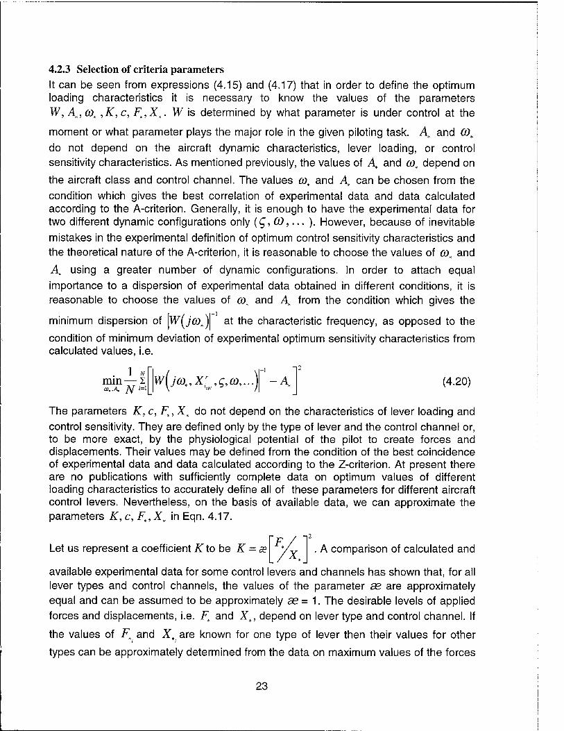
4.2.3 Selection of criteria parameters
It can be seen from expressions (4.15) and (4.17) that in order to define the optimum loading characteristics it is necessary to know the values of the parameters W, A,, co„ ,K,c, F,,X„. W is determined by what parameter is under control at the
moment or what parameter plays the major role in the given piloting task. A, and CO,
do not depend on the aircraft dynamic characteristics, lever loading, or control sensitivity characteristics. As mentioned previously, the values of A, and cot depend on
the aircraft class and control channel. The values cot and A, can be chosen from the condition which gives the best correlation of experimental data and data calculated according to the A-criterion. Generally, it is enough to have the experimental data for two different dynamic configurations only (£, CO,... ). However, because of inevitable
mistakes in the experimental definition of optimum control sensitivity characteristics and the theoretical nature of the A-criterion, it is reasonable to choose the values of CO, and
At using a greater number of dynamic configurations. In order to attach equal
importance to a dispersion of experimental data obtained in different conditions, it is reasonable to choose the values of co, and A, from the condition which gives the
minimum dispersion of Iw^fi).)! at the characteristic frequency, as opposed to the
condition of minimum deviation of experimental optimum sensitivity characteristics from calculated values, i.e.
. 1 * mm— I a.,A. _/V ,=I
w(m,xi,g,co,..) -1
-A (4.20)
The parameters K, c, F,,X, do not depend on the characteristics of lever loading and control sensitivity. They are defined only by the type of lever and the control channel or, to be more exact, by the physiological potential of the pilot to create forces and displacements. Their values may be defined from the condition of the best coincidence of experimental data and data calculated according to the Z-criterion. At present there are no publications with sufficiently complete data on optimum values of different loading characteristics to accurately define all of these parameters for different aircraft control levers. Nevertheless, on the basis of available data, we can approximate the parameters K, c, Ft,X, in Eqn. 4.17.
Let us represent a coefficient K to be K = a? F. A comparison of calculated and
available experimental data for some control levers and channels has shown that, for all lever types and control channels, the values of the parameter ae are approximately equal and can be assumed to be approximately se = 1. The desirable levels of applied forces and displacements, i.e. Ft and Xf, depend on lever type and control channel. If
the values of F, and X, are known for one type of lever then their values for other
types can be approximately determined from the data on maximum values of the forces
23

and displacements that can be attained by a
(Fmax, Xmax). The available materials give
F / X / F_. ' 7x
human using different control levers
us a reason to believe the ratios
are approximately constant for different control levers
= const, = const). The values Fmax and Xmax are provided in max;
literature, for example Reference [6]. They are dependent not only on whether one or two arms or legs are used in operating the control lever, but also on the location of the control lever relative to the pilot. For example, with a wheel control is performed using both arms while with a centerstick control is performed with one arm. With two arms a man can exert maximum forces about 1.5-2 times larger than with one arm, while the possible range of movement of the arms is roughly the same for both cases. These considerations, as well as a comparison of the calculated and available data, allow us to assume that the values of Ft and X, for the longitudinal channel of a transport
aircraft are as shown in Table 4.1.
Table 4.1
Characteristics Wheel Centerstick Sidestick
F*,kg 6 3-4 1.5
x*, mm 25 25 20
4.3 Recommendations for selecting the sidestick loading characteristics
4.3.1 Loading gradient Among the various control lever characteristics the loading gradient is the most important. In addition to providing the optimum level of control forces, displacements, and centering features, the loading gradient has greater influence on the pilots ability to regulate his control actions than other lever characteristics. This is due to the fact that the aircraft response is in proportion to the magnitudes of the lever displacement and the applied forces.
In order for the control lever to have the desirable feature of returning to its center position when released, the gradient value must be positive Fx> 0. Taking this into account, from the Z-criterion, the minimum of the function (4.15) occurs when:
F Op!
F.-(l + K -c){F0 + Ffr) + K -c(X.- A,Xr)
Ajr{\ + K-c)
where (F* = m = 0), Xr = Xr -\w(jco)\
(4.21)
24

This expression is valid when the numerator is greater than or equal to zero. Otherwise the optimum Fx is equal to zero.
It can be seen from Eqn. 4.21 that the optimum loading gradient is a function of other control lever characteristics. With an increase of the values of the breakout force F0 ,
coulomb friction Ffr , loading damping F x , or sensitivity of control Xr, the optimum value of the loading gradient decreases. The dependencies shown in Eqn. 4.21 correlate well with experimental data (for example the data shown in Fig. 4.3).
At the optimum value of control sensitivity Xr from the Z-criterion, i.e. from the condition
of the minimum of function 4.15 with respect to the parameters Fx and Xr
dFx ~ dXr ~ (4.22)
For the case Fx — F0 = Ffr = m = 0 and assuming a small value of the constant c, we
have approximately
F;\r = x:pt,Fx=F0=Ffr=o =
F^ Y (4.23)
As the desirable levels of forces and displacements Ft and X„ depend upon lever type, expression 4.21 indicates that the optimum loading gradient values are different for different control levers. The ranges of optimum loading gradient values for
F0, Ffr, Fx close to zero and optimum control sensitivity are given in the Table 4.2.
Table 4.2
Control channel Wheel Centerstick Sidestick Pedals
Longitudinal, kg/mm 0.15-0.35 0.08-0.25 0.05-0.20 0.2-0.5
Lateral, kg/mm 0.05-0.1 0.05-0.2 0.4-0.15
The sidestick data given in Table 4.2 correlates with the results of experiments from flight simulators (Fig. 4.13). Figure 4.13 presents the values of sidestick optimum loading gradients for the longitudinal and lateral channels obtained from flight tests on the Tu-154M in-flight simulator. It should be mentioned that to assess the validity of the results obtained, the same pilot and the same sidestick were used on the ground and in-flight simulators. Fig. 4.13 also shows data for the sidestick on the A-320. The data presented confirms the validity of the regions of acceptable sidestick loading characteristics and the Z-criterion.
When the loading gradient deviates from optimum the controllability degrades as shown in Fig.4.14. Controllability degrades more with a decrease from optimum, i.e., the pilot rating at Fx = 0 is worse than the pilot rating as Fx —» °°. This correlates with practical
25

experience. There are airplanes, such as the F-16, with a fixed stick, i.e. Fx —>°°. Also, control redundancy for jammed control levers can be provided by sensing the forces applied to the stationary lever. However, there is no available information for cases when the gradient of lever loading had a zero value.
4.3.2 Breakout force The breakout force is usually introduced with the aim of keeping the control lever cente- red. From Eqn. 4.1 it follows that when the pilot does not apply any forces to the lever (F = 0), it will return to the neutral position (X = 0) if the value of breakout force is greater than coulomb friction {F0>Ffr). With this in mind the magnitude of the
breakout force is usually designed to be greater than the friction in the linkage. But even in the absence of friction a certain amount of breakout force improves the controllability. This can be seen from the results presented in Figures 4.15 and 4.16. Analysis of available and obtained experimental data shows that, in the absence of coulomb friction, the optimum values of breakout force in the longitudinal channel are approximately equal to 0.5 kg for a sidestick, 0.7 kg for a centerstick, and 1 kg for a wheel.
The differences in optimum breakout forces for wheels, centersticks, and sidesticks are due to the differences in the way humans generate forces with these control levers. For centersticks and sidesticks the optimum breakout forces in the lateral channel are approximately the same as, or slightly greater than, those in the longitudinal channel. This is in spite of the fact that the force capabilities of a human are about 1.5-2 times greater in the longitudinal channel than in the lateral channel. However, if the breakout forces are not approximately equal, there may be large involuntary "interferences" in the lateral channel due to pilot inputs into the longitudinal channel. This is confirmed by flight tests and practical experience. For the A-320 the sidestick breakout forces are F0
= 0.4 kg in the longitudinal channel and F0 = 0.6 kg in the lateral channel. According to the results of flight research on the Tu-154M in-flight simulator the optimum breakout forces are F0 = 0.4 kg in the longitudinal channel and F0 = 0.3 kg in the lateral channel.
Breakout force is also useful for those cases where, for whatever reason, the force/response gradient is too small or the control sensitivity is too high, that is when the level of forces required of the pilot to perform the task turns out to be considerably less than the desired forces. This is evident from the Z-criteria. Indeed, from the minimum of the function (Eqn. 4.15) with respect to F0, considering that the condition for centering the control lever requires F0>0, one can get the following expression (at
Fi=m=0y.
r K-(l + K-c)(AXFx + Ffr) + K-c(X>-Ajr)
1 + K-c
which is valid for a positive numerator. Otherwise F0 is equal to zero.
26

This dependency is confirmed by experimental data presented in Fig. 4.17 showing the dependency between the optimum values of Fo on Fx for a centerstick. There was not any sufficiently complete experimental data to plot a similar dependency for the sidestick. However, as can be seen from Figures 4.15 and 4.18 and the relation (4.17) breakout force effects the optimum values of control sensitivity characteristics according to the trend presented in Fig. 4.18 for the lateral channel.
It should be mentioned that for large values of F and in the absence of friction, breakout forces are necessary to make the aircraft insensitive to involuntary actions of a pilot and to aircraft vibrations.
4.3.3 Loading Damping The role of this parameter has not been studied sufficiently for sidesticks or, for that matter, other control levers. Experiments show that when coulomb friction is small or absent, an introduction of sidestick damping leads to improved pilot control (Fig. 4.19) and improved pilot ratings. In ground simulation and flight research pilots noticed an increase PIO tendency for sidesticks without damping, especially in the lateral channel.
The positive effect of sidestick damping on aircraft controllability can be explained in these cases by the fact that it increases the damping of the "sidestick + arm system". This damping is very small because of the small damping provided by the muscles governing the movements of the arm, especially in the lateral channel. As far as this "system" is part of the "pilot - aircraft" system, introduction of damping reduces the oscillation and PIO tendency of the system as a whole. Besides this, due to the increased damping the pilot obtains feedback of a stick displacement velocity that allows him to more accurately control his actions and reduce pilot errors. Finally, sidestick damping reduces the influence of aircraft structural vibrations and inadvertent pilot inputs.
Figure 4.20 depicts the advisable region for sidestick loading damping Fx depending
on loading gradient Fx. It can be seen from the data that optimum values of Fx for a sidestick depend weakly upon the loading gradient value Fx and can be considered equal to:
Fx = 0.0015 - 0.002 kg I mm IS for both longitudinal and lateral control
channels.
From the Z-criterion, i.e. from the minimum of the function (4.15) with respect to Fx, we obtain
27

(4.25) It can be seen that decreasing the sidestick loading gradient increases the optimum damping value. In this case the damping causes additional loading influence, therefore an introduction of damping coefficient improves pilot ratings.
It should be mentioned that the estimation of lever loading parameters depends upon control sensitivity characteristics. Selection of lever loading parameters must also consider the characteristics of a particular aircraft.
4.4 Calculating the optimum values of control sensitivity characteristics of Class III aircraft equipped with a sidestick A technique is described here which allows the calculation of the optimum values of longitudinal (F , Xn ) and lateral (F , X ) control sensitivity characteristics of Class III
aircraft equipped with a sidestick. These characteristics can be defined from the preceding A- and Z- criteria if the magnitudes of the relevant constants are specified. In order to select the optimum control sensitivity characteristics, we will choose a type of
transfer function W. in the longitudinal and lateral channels (which appears in the A-
criterion) which considers the interdependence of coordinates in every channel. For classical aircraft, deflection of the control lever in the longitudinal direction simultaneously generates a pitching motion and a normal acceleration. A deflection of the control lever in the lateral direction generates a roll and turns the flight trajectory. The relative magnitudes between them depend upon flight velocity V
r q =
8 \
n V An (4.26)
V V s (4.27)
where s is the Laplace operator; q, p, iff are the angular velocities of pitch, roll and
heading; Anz is the normal acceleration; g is the gravity constant.
This leads to the fact that at low flight speeds the angular pitch velocities will have a strong impact on the choice of the characteristics of the longitudinal (F , Xn ) and
lateral (F , X ) control sensitivity characteristics. On the other hand, as flight speed
increases, the importance of the normal acceleration and heading responses increase.
28

To account for this effect for aircraft amplitude-frequency characteristics (AFC) \W I, we
W and of pitch velocity will use a linear combination of the AFC's of g-load
longitudinal channel, and a linear combination of the AFC's of roll velocity
heading rate Wf in the lateral channel:
W
W
in the
and
K(^)| = K(^)| + -^K(;6))|; 8 (4.28)
\w(jco)\ = \Wp(jco)\ + k\w.(jco)\,
where V0 and k are the weighting coefficients.
Taking into account these relationships and Equations 4.26 and 4.27, the A-criterion assumes the following form for the longitudinal channel:
f i+A CO +
V n^§ V
1-1
Wnz(jcot,x:-,gsp,CDsp,..) AZ(F\F0,...)
(4.29)
The values of the coefficients V0 and co, are defined from the condition of the best correlation of the calculated and experimental data and have the following values:
^=140^; co^O.ls-1
The optimum value of parameter -F can be defined from the relation
~Fopt = Px ■ Yopt
n. n.
Figure 4.21 presents the dependence of the parameter A/ (appearing in Eqn. 4.29) upon the gradient Fx, which was obtained with other sidestick loading characteristics
equal to zero. The parameter A/depends not only on Fx, but also on F0 , F*, and Ffr
and can be defined by Eqn. 4.17, where c=2.5 mm/kg , as=1, F,=1.5 kg, Zs=20 mm,
and A = 05.
For the lateral channel:
'( l + k
V co '*J \wp(jcot,X°;',g,...)\ = A(F\F0,...), (4.30)
where k = 14; cot= 1.25 s'1;
29

Ar can be determined from Figure 4.22 as a function of Fx with all other values of sidestick loading characteristics equal to zero. The dependence of Ar upon Fx, as well
as Ffr and Fx is defined by Eqn. 4.17, where c =5 mm/kg, se= 1, Ft=1.5 kg, X,=20
mm, and As = 7 "^.
The optimum control sensitivity characteristics in the lateral channel Fp can be defined from the expression
■popt _ -px _ V°P' p ~ p
Thus, equations 4.29 and 4.30 allow us to calculate the optimum Fopt, X°npt, F"p
p! and
X°J" keeping in mind:
- flight velocity Vand the value of parameter n ;
- values of Fx, F0 and other loading characteristics;
- aircraft transfer functions from sidestick displacements to normal acceleration Wn
and angular roll velocity W . It should be noted that in this case the gain coefficient
in the transfer functions must be presented through the characteristics Xn and Xp.
If the AFC's of transfer functions Wn and Wp are known, or, to be more precise, their
values at characteristic frequencies CO,, and the values Xn and Xp as well, at which
the AFC's were defined, then the optimum values X°pt, XJ'can be defined from the
following relations:
XZ=At{F',F0,..)-\l + Vn
n, g \co? +
r \2
V J
X°;=Ar(F\F0..)-
V ^.(M.XJ X
(4.31)
X.
4.5 A comparison of experimental and calculated results To determine the effectiveness of the above technique and to qualitatively define the degree of dependence of optimum control sensitivity characteristics upon aircraft dynamic characteristics, this section will consider the influence of the principal longitudinal and lateral dynamic parameters on the optimum values of
F°pt, Xopl, Fopt, Xop! as obtained from calculated and experimental data.
30

Since the characteristics of the long-period motion have no noticeable impact on the values of the AFC's of the transfer function Wc at frequencies on the order of
CO, = 0.7 s~l, then from the A-criterion (Eqn. 4.29) it follows that they do not influence
the optimum values of the characteristics F°pt and IJ'. This conclusion is confirmed
by experimental data. Therefore, we shall consider the effects that only short-period
motion parameters have on the optimum F°pt and X°f ■ opt
Usually, the short-period aircraft motion is decribed by a transfer function of the following type:
sp /
/X TX7 / n~ —ST
WVr f + 2s co s + ay * <4'32' ~sp sp sp
In this case from Eqn. 4.29 we get the following expression for the definition of the ■opt
optimum values F°pt and X°p :
fn, 8^ 2
V Xopt = -co2 2c" ' v A, sp
It can be seen that the optimum values F°pt and X°pt depend on the natural
frequency COsp and damping 2gspCOsp of the short-period motion of the aircraft and also
on the parameter n and the flight speed V.
Figure 3.23 presents the calculated and experimental dependencies of the optimum
values F°pt on the natural frequency COsp. This data shows that the optimum values
X°nP , F°p are practically equal for short-period frequencies within the range
1 < cosp < oo with the condition that (l - 2g2p)co2/co2
p = 0 (for instance, at gsp = 0.7).
At COsp > 1 the ratio y «1. Then if equation 4.33 is expanded as a Taylor series
on «y, : /CO'
31

Xop' = 1+A nr g
CO + V V ) sp
(4.34)
With a decrease of the natural frequency from (Osp = co^ = 0.7 s ' and if
2^ C0S = const > 0.7, the optimum values X"pl, F"pt decrease approximately in
Xop!~co2; Fopt~co2
3sp sp
proportion
*
It should be mentioned, that for aircraft which have little or no stability augmentation, as in previous generations of aircraft, the conditions a>sp>\s~l, and/or gsp =0.7 are
usually met and, therefore, one should consider Xop' and F°npt to be independent of
COsp. More modern aircraft may have low stability margins when their stability
augmentation fails and these conditions may not always be met. Therefore, when considering the problems of flight safety in modern aircraft it may be necessary to
account for the dependence of the optimum values Xopt and F°npt on wsp. For statically
unstable aircraft, where CO2 < 0, the traditional characteristics Xn and F make no
sense at all, since in this case the steady value of g-load is absent. In this case the ratio of controlling moment magnitude (in pitch accelerations) to the lever displacement or the initial control force (for a step input) can be used as control sensitivity characteristics. This technique allows one to estimate the advisable magnitude of the control sensitivity characteristics.
With a decrease of damping (gsp or 2gspO)sp) the optimum X°npt and F°ptincrease. The
influence of damping on these values depends on the natural frequency in the following
way: the lower the COs , the more influence damping has on the optimum Xop and
F°npt. This can be seen from Figure 4.24 and Eqn. 4.33. Figure 4.25 presents the
calculated and experimental dependencies of optimum values of Xn , Fn on the
parameter nz . This data shows that, starting from approximately nZa= 10, a decrease
in n^ leads to an increase in optimum X F . At values of KZa > 10, the optimum
Xn , Fn do not really depend on the value of nZa. From a qualitative standpoint this
dependency was already known. However, the quantitative differences between the various cases were not sufficiently clear. The proposed technique makes it possible to solve this problem for different aircraft characteristics in a quantitative respect as well.
32
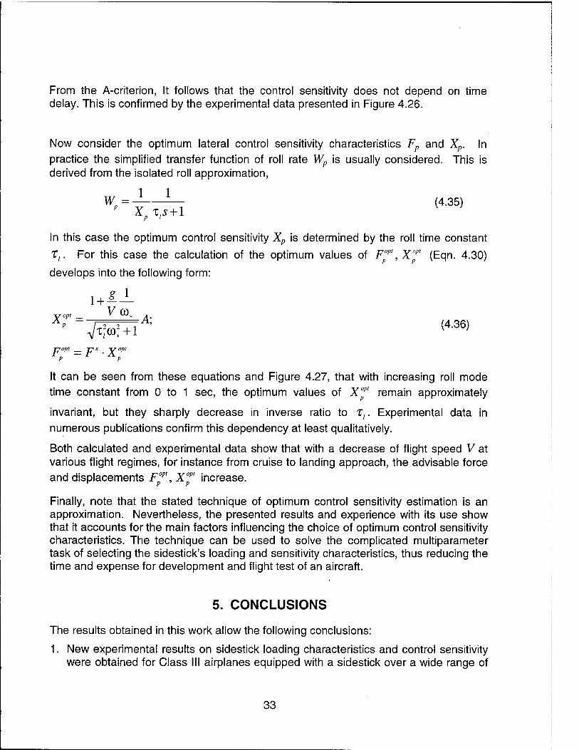
From the A-criterion, It follows that the control sensitivity does not depend on time delay. This is confirmed by the experimental data presented in Figure 4.26.
Now consider the optimum lateral control sensitivity characteristics Fp and Xp. In practice the simplified transfer function of roll rate Wp is usually considered. This is derived from the isolated roll approximation,
WP=^ '-T (4-35)
In this case the optimum control sensitivity Xp is determined by the roll time constant
T,. For this case the calculation of the optimum values of Fopr, X"1" (Eqn. 4.30)
develops into the following form:
yopt _ * CO* A
p
popt _ T?X _ V°P<
P P
It can be seen from these equations and Figure 4.27, that with increasing roll mode time constant from 0 to 1 sec, the optimum values of Xopt remain approximately
invariant, but they sharply decrease in inverse ratio to Tl. Experimental data in numerous publications confirm this dependency at least qualitatively.
Both calculated and experimental data show that with a decrease of flight speed V at various flight regimes, for instance from cruise to landing approach, the advisable force and displacements fop\xopt increase.
Finally, note that the stated technique of optimum control sensitivity estimation is an approximation. Nevertheless, the presented results and experience with its use show that it accounts for the main factors influencing the choice of optimum control sensitivity characteristics. The technique can be used to solve the complicated multiparameter task of selecting the sidestick's loading and sensitivity characteristics, thus reducing the time and expense for development and flight test of an aircraft.
5. CONCLUSIONS
The results obtained in this work allow the following conclusions:
1. New experimental results on sidestick loading characteristics and control sensitivity were obtained for Class III airplanes equipped with a sidestick over a wide range of
33

airplane dynamic characteristics. The major influences of these characteristics on airplane handling qualities were revealed.
The comparative analysis of controllability provided by a sidestick and conventional controls shows that in standard flight conditions and with proper selection of controllability characteristics, the sidestick provides handling qualities similar to those provided by conventional controls. However, the advantages and disadvantages of the sidestick from a handling qualities point of view is still not quite clear. Despite the fact that pilots usually prefer control by means of a sidestick, the accuracy of control in the longitudinal channel, as well as left-hand control in the lateral channel, is somewhat worse than that provided by a wheel. Controllability with a sidestick during emergency situations requires particular attention and further investigation. The expediency of the sidestick application must be considered separately for each case.
The theoretical approach and criteria for the optimum control sensitivity and loading characteristics have been developed further. The parameters included in the criteria were specified and a technique to calculate the characteristics was developed. It was shown that the calculation results conform to the available experimental data both qualitatively and quantitatively. The loading and control sensitivity characteristics calculation technique considerably reduces the experimental investigations, and hence, reduces aircraft development time and expenditures.
It is expedient to continue the investigation in order to specify the theoretical approach and the controllability criteria for other types of aircraft (Class IV airplanes, helicopters, etc.) and on this basis create a new controllability criteria for various control lever characteristics.
34
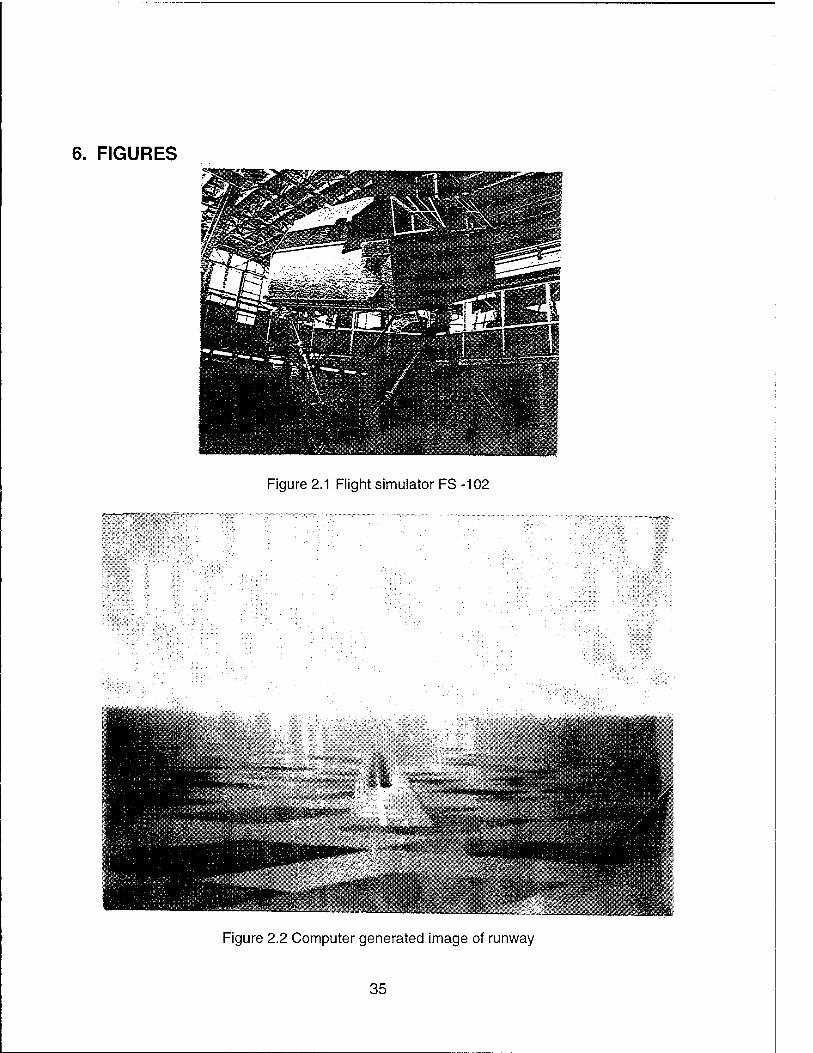
6. FIGURES
WKKSI
RHH
i^aUL
Itlll
Figure 2.1 Flight simulator FS-102
»'ssiaft'-^
Figure 2.2 Computer generated image of runway
35
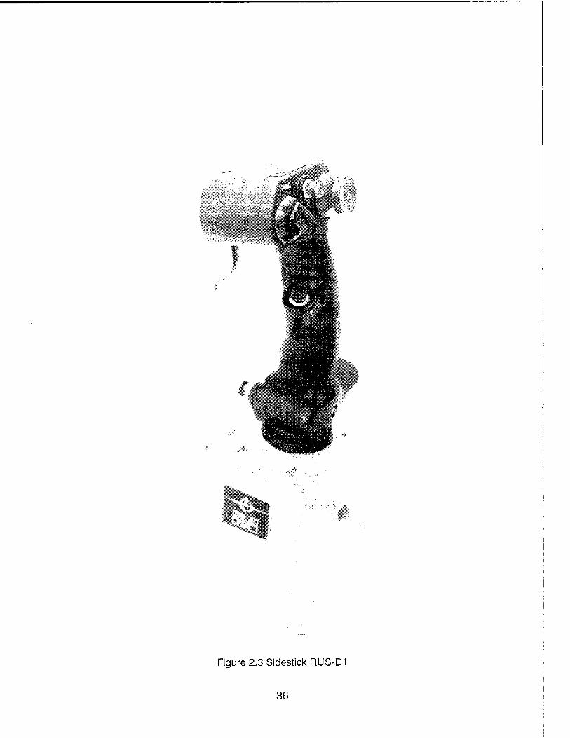
Figure 2.3 Sidestick RUS-D1
36

Figure 2.4 Constructive scheme of sidestick RUS-D1
37

Figure 2.5 Sidestick with electro-hydraulic loading system
38

Xmin. Astl Xl
/\ X St., XynUX A
Parameter Ranges of Variance Pitch Roll
Breakout force F0, kgf 0-5.0 0-3.0
Force/Deflection gradient F*2, kgf/mm 0-0.5 0-0.3
Location of loading break point, X\, X2; %X max 0-25.0 0 - 25.0
Loading force gradient after breakpoint, F2\, kgf/mm 0-0.5 0-0.3
Force "step", Fst, kgf 0-10.0 ~
Location of force "step" Xsu %X max 0-90. ~
Figure 2.6 Typical loading law and the range of the loading parameters reproduced by the ECLS
39

central stick side stick
■.■■A.i
.. i. ■ i.. ■. i: i .....; i
; ';.'.ü:l;L;;'.-.'.:-.t.^;iii;. ;:;-.v.-_.i:::i::.'..l:-.::;ii:
m f;!::;:; r;i!:::rj(::'!:!!ii::.T;:i.!:f.;lffr
:;ÜföHi ill
■r
S3
.;:I;L;'.I, '■.■.:;::U4
tf
03!iimi!il!IB VMiim-'tm'-miBi!
ifiiiiniNiiiiliiijilffif!
1 iiiili'i':! V-i'iliiitoi P'ilP ^ J&#JliiiSi!
;;J:.!f:ii{f.-J:-:i"i.'/::.'f.'////
Figure 3.1 Piloting performance of a spacecraft at landing
40

Pi Int I •—• side stick >;—x wheel
h confidence interval J
i !
2*01^ = ,?; 7l£oi=5
instruiRsntätion tiiont without svctom nf r'ho visiisiicsHnn V ■ 4 w I ^VMUl.lWMV^Vii
^ , s"
Fiioht with the visuaUsa^on «vct£">
<*iP, *"*
Figure 3.2 Pilot rating depending upon longitudinal short period frequency
41

Pilnr R
6 4
\
side stick _£ central stick
Cue» =3,5s' n^ = 30 >sp
Vo = 250 m/S
2}C0sP, S -1
side stick Pilnr I
Jm v v it —>( wheel
-u
. i COsp = is' ?lZgC - S
V0 = 2 60 #M/h
2$OiP, s-
Figure 3.3 Pitch stabilization error of the aircraft with the centerstick and sidestick and pilot rating of the aircraft with the side stick and wheel in dependency of the longitudinal short period
movement damping
42

Piiot model: W(p) = K e -pr
« mi
0
ciria
chrlf l
0.1
■H
0>: lover« ^ V » Wit-"
4J 5 0 H rl &
0,2 T, s PiXot delay lt_
Figure 3.4 Lever type influencing on dynamic properties of pilot
K-oXX mode time con.sta.rxt IT.
'L - 10 S
6
10
0 H XX
w '/A
§ w 0 H
wheel
side stick
central stick
Figure 3.5 A Comparison of roll stabilization accuracy while handling the wheel, sidestick and centerstick
(the data are common for 5 pilots)
43

^ pedals
Pilftf- I t Jm ik V V tl Pilot B Onoratnr 1
Figure 3.6 A comparison of yaw stabilization accuracy while handling with the sidestick and pedals
Total lateral motion (roll+yaw)
\ pedals
side stick:
Figure 3.7 A comparison of roll and yaw stabilization accuracy while handling with the sidestick and pedals
44

Spatial motion (pitch+roll+yaw)
^ pedals
side stick
Figure 3.8 A comparison of roll and yaw stabilization accuracy while handling with the sidestick and pedals during landing approach
(data are common for 3 pilots)
ni'lAHn« orrnr
-Gi/&z
\ $0
rinVif i.. . liyui,
VianrI iiunu
luil j •
llUUU l
III — frairn'nn Aiv Lj.uxnj.iiy uuj vc
Figure 3.9 Left hand piloting accuracy of right handed pilots
45

Figure 3.10 Sidesticks with uncrossing axes
Stick of "Grip" type
■ ■^"f&l/X ''S? "!
46
?H#«

Je- «& 70
/ I
-16° 2,0
-6" 0.4- " i
I I I I
I *^ -0,4 6 * -2.0
16" x.
-70
Fü.Kgf
SO'
3.0
0.6
*Z6
■4.0
20- y
Figure 3.11 The loading characteristics of A-320 sidestick
PR
10
5
%
I )> ■
3 H O u Ä O W-H
5 ft
6 4-1 JJ
: -H -H - ■ ' u U ' 2.° 1 Dl-H '
(0 p, :
"button",
priority
\-
general
mechanical'
bond
—-v^——: -T—' in/-) ma/iharn iial 1u
Figure 3.12 Pilot rating of different methods of two sidestick interactions (Ref. 16)
47

F
tr
Sensort FEW
^J 1 |
IQ
1 30 i..
F f ^
Str
Sensor A£ FBW
-10}
F.
-/ff
\I0 20
^ -vf I I
^\iP^'" VO 30 t.
t—~-. H Trim time
Figure 3.13 Manual electrical force trimming of a sidestick
inm time
Figure 3.14 Semi-automatic electrical force trimming of a sidestick
Trim time
Figure 3.15 Scheme of a "fast" force trimming of a sidestick
48

feel "system ~~"%,H...
> -vw^-
stability augmentation system
trimmer
>4 x
linkage
A $,M.
transfer coefficient
Figure 4.1 Aspects influencing the aircraft lever loading
Figure 4.2 Static characteristics of lever loading
49

ü) -d
£ ..£ i
Q-
X o
C3 c c CG .c
00 o i CO
1—
<0 CD
1 CO
.. •*
.. w>
■- Oi
co o
'cO
o 4—• CO CD -g co
co ü
w '^_
CD -*—« O CO 1—
CO .c o
cö £Z CD CO
o o CD
O
«^ £
X
^ 03 CD
i c <5> 00
c CO
' ü
"cö c
"C 3
Cs -1—'
-5- D3 1 C
o
es I
C0
o CD c
_C0 Q.
_c co c o
'03 CD
CO O) C
*■!—»
C0
]g E in
CD
13
LL

a
V*1
IS
\ ct
\ -f*
1
•
a
8: to to
Co
I
Co
C3 CO
CD 00
I
r /
<
\
CO II
* •
X o
CD
CD
CD CD
CD 00
o «XI
(
: «1 «
•a
m M a; >
/ °
9
o
to/
/ **
r «
ii
e
6 ^ ^
\\ >n ii
e \
Of cv fo <r *o
CD
t
CD
§
CD CO
c? ^0
fir
/ 0 /
/9
•*-©/
>o
CD CD II * ■»I
•»
1 1 i\
\*
CD
03
CD
CD CD
CO
CD
co
c
CO
o 'o. o .c
c o c CD
CO O
w
o CO
CO
D) c
CO _g
o "■4—«
(0 0
■g 'co ■D c CO
w c CD co
c o o
"cö
«*—* 'u> c o
_J
CD
13
ID
Q. <M K> «O ^ cv *■> -<r ««

T> /
i r *0 .
v> It
■>»
ca-
ll
\
y=o • II K
00 \
uS
«5
C3
O •3"
o
•
'• 6
/ <
/•
4<^ *
It
•
•
I
C3
<
Z
o O
0
05 U_
CM
cvt "O c\j ^ •o

1 £
st
o" x "
• •/
/*
1 ^
•\
>
- DJ
E v O.
*o
<o
■*
to
f\£
• «vi
S x"
a. •
• / ** • /
««l. »•
•\ «VJ\
C«\ v«
\ H
V <
1
CV «5 >o en Q. m
/ •
*\ \»
\ • \ •
o x "
a.
•
-H 1— 1 1
■■•»•
a
i „ O-
QO
V0
<o
to
CV
» /
A) P
L ^£
Sc i/> -T O o"
u X
Ci
\ • \ «0
^ \
—i i
**■'•" . v>
'•«a •if» v.
£ .
K..
VO
f)
«V
r •
<-<£ u.
<5>"
<5>*
$9
• /
•
•/
/ -*
£ OP**"-
0. 0
X " Ci- •i
• \
\ ^
• n
1 1
er» v. -6
E
V0
«V
CO
"■4—'
CO
o 'Q. CD c o c CD 3
en c
'■a co o
0
co 0
■g "cn -a c CO
CO c CD co
<s ' _
c O Ü
CO 1—
a> OB _J
D)
U-
CO LO
Sf- to vO £ * N> a fO

Figure 4.6 Deflections of control lever at estimating the control sensitivity
XB *10"* 0.20 +
0.15
0.10
0.05 \
n on ^AA/^A/ w\. Wfc ö
0.05 .1 0 .2 ' 0 .31 ' 0 A T 0 .5
Figure 4.7 Spectral density of presented lever deflections
54

side stick central stick calculation
confidence interval $-0.9
10 Xnj.fept
different aircraft „ and control levers '
Figure 4.8 Pilot ratings worsening at deviation of control sensitivity characteristics
55

£ opt y
7* /
/ Fopt
Figure 4.9 Graphic of Minimum
2
\ a.
iO 100 v mm/
Figure 4.10 Dependence of pitch stabilization error dispersion on control sensitivity (Ref. 11)
56

Figure 4.11 Aircraft amplitude-frequency characteristics at optimum control sensitivity
3 ^.—-» : —
•
_2 \
7 • \
^c
// — — o;c
— &Kp
r
Q.i 1.0 1° £/fypt
Figure 4.12 Dependencies of the total gain coefficient kK and cut-off frequency of "pilot- aircraft" system on control sensitivity
57

FKS/ 't jmm
0,2
QA
0,05
0,025
• //
A- 320'
flight simulator
1 0 D • ■
inflight simulator TU-154-
"Viv //
■ I..-M - M , 1 1
a m o •.
—i—
int off
o cockpit cockpit
—t
0,015 0,05 OH 0,1 Ft «eg/, mm
Figure 4.13 Optimal values of the sidestick gradient
P£
0 0,1 0.1 0.5 0,4 v^ F K9/ mm
Figure 4.14 Influence of the sidestick loading gradient on pilot rating
58

Q.
« tx.
O
If)
o
co
03
o '5. c o
-t—»
o CO 0 ^_
-Q
CD
CD O c CD
CD
CD
c\J on
o» Ü f 03 ■D ^-^ c
fc CO £ >*
a. X > o CO *— c
CD CO
O i_
CO c / o Ü
CO k_
0
CO to
/ 0 sz M- CO O D) 0.E c 2 05 *- 3 O
<T 5= = C Q.
■* "3
3 CO g> 0
Ü- £2
IT)

Jvs x • experement —■ Z-criterion .
calculation
. k >^
• N
^Xni0L -'50 g V\"
■"X nZcC-
%\
0, 0,1 0, 0,3 F, % mm
Figure 4.17 Influence of the loading gradient on the sidestick breakout force optimum values
mm g-mgs -i
-6
-5
►
»
0.15 0,6 F0,K2
Figure 4.18 Influence of the breakout force on the aircraft control sensitivity
60

averaged £>y,!;3* tests
0.25
O.OOi 0,001 0,005 0£H 0,01 0.05 F <g /mm s
O.OOi O.Oi 0.01 0.03 F**2/mm&'
Figure 4.19 Influence of the sidestick damping on the pitch stabilization accuracy
61

PR
3
0,001 O.OOZ 0.003 p*K« /„,„,. s-'
PR \ ■
« • P*= 0.03 s °/mm
I ■
■ « « \ ••
c <. • v ■
lateral X. 1
7 •
9
channel 1 \ i
j i
! 1 O.OOt 0,002 0.01 0,02 COS p, "S/mm-s'
Figure 4.20 Influence of the sidestick damping on pilot ratings
62

*e, ■mm
40 ...
longitudinal ekaiiiis
20
0,1 0.1 0.3 p.\£i_
Figure 4.21 Dependence of parameter A, on sidestick loading gradient
HZ, yntn
2
late chan
ral , nel ■
^ ■
0.1 0.2 0.3 -x
u- mm.
Figure 4.22 Dependence of parameter Ar on sidestick loading gradient
63

h..
8
i
_J
^7 f / ] £SP -07
TSPH*
0.5 i £ Wc,P) s -i
Figure 4.23 Influence of the longitudinal short-period motion frequency CO on the optimum
F„ values
F»:
(0 """^^N v ""•*-«»
V x 260 K%
-^ -— —i
CO&p-is-i
0,5 10 1.5 5 SP
Figure 4.24 Influence of the longitudinal short-period motion damping £ on the optimum Fn
values
64

copi/ v*r6
-i
C0SP ?- \ c"
V=200K%
3no
ÄOO
800
<0 i5 n *<*.
*<,
-15
C0sp = 2s"(
\ = 0,7
10 ft.
Figure 4.25 Dependence of the optimum Fn values from 7lz parameter
65

J-U
10
IT ir
CJ5P= 2 s"
W » 0.7
o
.0.5 -. <-° i s —
Figure 4.26 Dependence of the optimum Fn values from time delay
2-° <Us
Figure 4.27 Dependence of the optimum Pxvalue from roll time constant^
66

7. REFERENCES
1. Adamovich N.V. "Machine controllability." M.:Mashinostroyeniye, 1977, 1977, 277 pages.
2. Bushgens G.S., Studnev R.V. "Aircraft dynamics. Dynamics of longitudinal and lateral motion." M. : Mashinostroyeniye, 1979, 3 52 pages.
3. Guskov Yu.P., Zagainov G.I. "Aircraft flight control." M. : Mashinostroyeniye, 1980, 215 pages.
4. Common standards of civil transport aircraft airworthiness for the states - members of Council for Mutual Economic Aid. 1985, 47 0 pages.
5. Federal Aviation Regulation (FAR). Part 25. Airworthiness Standards: Transport Category Airplanes. FAR 1980.P.252-43 9.
6. Reference book on engineering psychology. /Edited by Lomov B.F./ M.: Mashinostroyeniye, 1982, 386 pages.
7. Zaichik L.E., Rodchenko V.V., Chernyavsky P.M. "Control sensitivity characteristics effect on piloting estimation." Scientific Articles of TsAGI, vol.17, #5, 1986, pp.86-93.
8. Zaichik L.E., Rodchenko V.V. "Estimation of optimum lever loading characteristics." Scientific Artickes of TsAGI, vol.21, #2, 1990, pp.84-93.
9. Zaichik L.E., Lyasnikov V.V., Perebatov V.S., Rodchenko V.V. , Saulin V.K. "Calculation method of a definition of optimum lateral controllability characteristics of unmanoeverable aircraft equipped with a wheel." TsAGI Transactions, #2477, 1990.
10.I.L.Ashkenas, D.T.McRuer "A Theory of Handling Qualities Derives from Pilot-Vehicle System Considerations." Aerospace Engineering. February, 1962.
ll.Efremov A.V., Ogloblin A.V., Predtechensky A.N., Rodchenko V.V. "Pilot As a Dynamic System." M.: Mashinostroyeniye, 1992, 33 6 pages.
12.V.V.Rodchenko, L.E.Zaichik, Yu.P.Yashin, S.Yu.Boris, A.P.Sopin "Control of unmanoeuverable aircraft equipped with a side stick." Conference Proceedings, Aircraft Flight Safety, TsAGI, 31 Aug.-5 Sept. 1993, pp.361-371.
67

13.Boris S.Yu., Eremin A.M., Rogozin V.V., Biryukov V.V. "Experience of flight researches of the side stick controllability on in-flight simulator as applied to unmanoeverable aircraft." Air Force Equipment, #2 (490), 1991.
14.H.Hopkins, Flight flies fly-by-wire Airbus Flight International, 9.13.1986.,p.26-27.
15.Beack G.T., Moorhouse D.I. Flying qualities design requirements for side stick controllers. AFFDL- TR-79- 3126, 1979.
16.L.G.Summers, J.H.Shannon, T.R.White, R.G.Shiner."Flight-by- wire Side Stick Controller Evaluation." SAE Technical Paper Series, 871861, 1987. (abstract in the journal "Aviastroyeniye" #43, 1989)
17.G.I.Zagainov, V.M.Shibaev, Yu.P.Yashin. "Introduction of a side control stick the the fight aircraft control loop.". Air Force Equipment, #3-4, 1987.
68