Embed Size (px)
Citation preview

INSTALLATION MANUAL
SAVE THIS MANUAL
SINGLE PACKAGE AIR CONDITIONERS ANDSINGLE PACKAGE GAS/ELECTRIC UNITS
DS -06 THROUGH -10 (6-1/2 TO 10 TON)
(10.3 EER)
035-19087-000 REV A (1102)
DS -06
-07
-08
-10
TABLE OF CONTENTSGENERAL . . . . . . . . . . . . . . . . . . . . . . . . . . . . . 5
SAFETY CONSIDERATIONS . . . . . . . . . . . . . . 5
INSPECTION . . . . . . . . . . . . . . . . . . . . . . . . . . . 5
REFERENCE . . . . . . . . . . . . . . . . . . . . . . . . . . 6
RENEWAL PARTS . . . . . . . . . . . . . . . . . . . . . . 6
APPROVALS . . . . . . . . . . . . . . . . . . . . . . . . . . 6
INSTALLATION . . . . . . . . . . . . . . . . . . . . . . . . 8
ACCESSORIES/OPTIONS . . . . . . . . . . . . . . . 25
OPERATION . . . . . . . . . . . . . . . . . . . . . . . . . . 41
START-UP (COOLNG) . . . . . . . . . . . . . . . . . . 45
START-UP (HEAT) . . . . . . . . . . . . . . . . . . . . . 45
TROUBLESHOOTING . . . . . . . . . . . . . . . . . 51
Complete Table of Contents on following pages.
Tested in accordance with:
NOTES CAUTIONS AND WARNINGSInstaller should pay particular attention to thewords: NOTE, CAUTION, and WARNING. Notesare intended to clarify or make the installation eas-ier. Cautions are given to prevent equipmentdamage. Warnings are given to alert installer thatpersonal injury and/or equipment damage mayresult if installation procedure is not handled prop-erly.
CAUTION: READ ALL SAFETY GUIDESBEFORE YOU BEGIN TO INSTALLYOUR UNIT.
ASHRAE 90.1 COMPLIANT

035-19087-000 REV A (1102)
2 Unitary Products Group
TABLE OF CONTENTS
GENERAL . . . . . . . . . . . . . . . . . . . . . . . . . . . . . . . . . 5
SAFETY CONSIDERATIONS . . . . . . . . . . . . . . . . . . 5
INSPECTION . . . . . . . . . . . . . . . . . . . . . . . . . . . . . . 5
REFERENCE . . . . . . . . . . . . . . . . . . . . . . . . . . . . . . 6
RENEWAL PARTS . . . . . . . . . . . . . . . . . . . . . . . . . . 6
APPROVALS . . . . . . . . . . . . . . . . . . . . . . . . . . . . . . 6
INSTALLATION . . . . . . . . . . . . . . . . . . . . . . . . . . . . 8INSTALLATION SAFETY INFORMATION . . . . . . . . . . . . 8PRECEDING INSTALLATION . . . . . . . . . . . . . . . . . . . . . 8LIMITATIONS . . . . . . . . . . . . . . . . . . . . . . . . . . . . . . . . . . 9LOCATION . . . . . . . . . . . . . . . . . . . . . . . . . . . . . . . . . . . 10RIGGING AND HANDLING . . . . . . . . . . . . . . . . . . . . . . 11CLEARANCES . . . . . . . . . . . . . . . . . . . . . . . . . . . . . . . . 12DUCTWORK . . . . . . . . . . . . . . . . . . . . . . . . . . . . . . . . . . 14DUCT COVERS . . . . . . . . . . . . . . . . . . . . . . . . . . . . . . . 14CONDENSATE DRAIN . . . . . . . . . . . . . . . . . . . . . . . . . . 17COMPRESSORS . . . . . . . . . . . . . . . . . . . . . . . . . . . . . . 17FILTERS . . . . . . . . . . . . . . . . . . . . . . . . . . . . . . . . . . . . . 17THERMOSTAT WIRING . . . . . . . . . . . . . . . . . . . . . . . . . 17POWER AND CONTROL WIRING . . . . . . . . . . . . . . . . . 17POWER WIRING DETAIL . . . . . . . . . . . . . . . . . . . . . . . . 18OPTIONAL GAS HEAT . . . . . . . . . . . . . . . . . . . . . . . . . . 22
GAS PIPING . . . . . . . . . . . . . . . . . . . . . . . . . . . . . . . . . . . . . . 22GAS CONNECTION . . . . . . . . . . . . . . . . . . . . . . . . . . . . . . . . 23LP UNITS, TANKS AND PIPING . . . . . . . . . . . . . . . . . . . . . . . 24VENT AND COMBUSTION AIR . . . . . . . . . . . . . . . . . . . . . . . 24
ACCESSORIES/OPTIONS . . . . . . . . . . . . . . . . . . . 25ELECTRIC HEAT . . . . . . . . . . . . . . . . . . . . . . . . . . . . . . 25MOTORIZED OUTDOOR DAMPER . . . . . . . . . . . . . . . . 25ECONOMIZER . . . . . . . . . . . . . . . . . . . . . . . . . . . . . . . . 25POWER EXHAUST . . . . . . . . . . . . . . . . . . . . . . . . . . . . . 25RAIN HOOD . . . . . . . . . . . . . . . . . . . . . . . . . . . . . . . . . . 25ECONOMIZER AND POWER EXHAUST . . . . . . . . . . . . 25
MINIMUM POSITION ADJUSTMENT . . . . . . . . . . . . . . . . . . . 25ENTHALPY SET POINT ADJUSTMENT . . . . . . . . . . . . . . . . . 25POWER EXHAUST DAMPER SET POINT . . . . . . . . . . . . . . . 25INDOOR AIR QUALITY (IAQ) . . . . . . . . . . . . . . . . . . . . . . . . . 26
PHASING . . . . . . . . . . . . . . . . . . . . . . . . . . . . . . . . . . . . 27BELT TENSION . . . . . . . . . . . . . . . . . . . . . . . . . . . . . . . 28AIR BALANCE . . . . . . . . . . . . . . . . . . . . . . . . . . . . . . . . 38CHECKING AIR QUANTITY . . . . . . . . . . . . . . . . . . . . . . 38SUPPLY AIR DRIVE ADJUSTMENT . . . . . . . . . . . . 40
OPERATION . . . . . . . . . . . . . . . . . . . . . . . . . . . . . . 41SEQUENCE OF OPERATIONS OVERVIEW . . . . . . . . . 41COOLING SEQUENCE OF OPERATION . . . . . . . . . . . 41
CONTINUOUS BLOWER . . . . . . . . . . . . . . . . . . . . . . . . . . . . 41INTERMITTENT BLOWER . . . . . . . . . . . . . . . . . . . . . . . . . . . 41
NO OUTDOOR AIR OPTIONS . . . . . . . . . . . . . . . . . . . . . . . .41ECONOMIZER WITH SINGLE ENTHALPY SENSOR . . . . . .41ECONOMIZER WITH DUAL ENTHALPY SENSORS . . . . . . .42ECONOMIZER WITH POWER EXHAUST . . . . . . . . . . . . . . .42MOTORIZED OUTDOOR DAMPERS . . . . . . . . . . . . . . . . . . .42
COOLING OPERATION ERRORS . . . . . . . . . . . . . . . . . 42HIGH-PRESSURE LIMIT SWITCH . . . . . . . . . . . . . . . . . . . . .42LOW-PRESSURE LIMIT SWITCH . . . . . . . . . . . . . . . . . . . . . .42FREEZESTAT . . . . . . . . . . . . . . . . . . . . . . . . . . . . . . . . . . . . .42
LOW AMBIENT COOLING . . . . . . . . . . . . . . . . . . . . . . . 42SAFETY CONTROLS . . . . . . . . . . . . . . . . . . . . . . . . . . . 43COMPRESSOR PROTECTION . . . . . . . . . . . . . . . . . . . 43
FLASH CODES . . . . . . . . . . . . . . . . . . . . . . . . . . . . . . . . . . . .43RESET . . . . . . . . . . . . . . . . . . . . . . . . . . . . . . . . . . . . . . . . . . .43
GAS HEATING SEQUENCE OF OPERATIONS . . . . . . 43IGNITION CONTROL BOARD . . . . . . . . . . . . . . . . . . . . 43
FIRST STAGE OF HEATING . . . . . . . . . . . . . . . . . . . . . . . . . .43SECOND STAGE OF HEATING . . . . . . . . . . . . . . . . . . . . . . .43RETRY OPERATION . . . . . . . . . . . . . . . . . . . . . . . . . . . . . . . .43RECYCLE OPERATION . . . . . . . . . . . . . . . . . . . . . . . . . . . . .44
GAS HEATING OPERATION ERRORS . . . . . . . . . . . . . 44LOCK-OUT . . . . . . . . . . . . . . . . . . . . . . . . . . . . . . . . . . . . . . . .44TEMPERATURE LIMIT . . . . . . . . . . . . . . . . . . . . . . . . . . . . . .44FLAME SENSE . . . . . . . . . . . . . . . . . . . . . . . . . . . . . . . . . . . .44GAS VALVE . . . . . . . . . . . . . . . . . . . . . . . . . . . . . . . . . . . . . . .44PRESSURE SWITCH . . . . . . . . . . . . . . . . . . . . . . . . . . . . . . .44ROLLOUT SWITCH . . . . . . . . . . . . . . . . . . . . . . . . . . . . . . . . .44INTERNAL MICROPROCESSOR FAILURE . . . . . . . . . . . . . .44FLASH CODES . . . . . . . . . . . . . . . . . . . . . . . . . . . . . . . . . . . .44RESET . . . . . . . . . . . . . . . . . . . . . . . . . . . . . . . . . . . . . . . . . . .44
START-UP (COOLNG) . . . . . . . . . . . . . . . . . . . . . . 45PRESTART CHECKLIST . . . . . . . . . . . . . . . . . . . . . . . . 45OPERATING INSTRUCTIONS . . . . . . . . . . . . . . . . . . . . 45POST START CHECK LIST . . . . . . . . . . . . . . . . . . . . . . 45
START-UP (HEAT) . . . . . . . . . . . . . . . . . . . . . . . . . 45PRESTART CHECKLIST . . . . . . . . . . . . . . . . . . . . . . . . 45OPERATING INSTRUCTIONS . . . . . . . . . . . . . . . . . . . . 45
LIGHTING THE MAIN BURNERS . . . . . . . . . . . . . . . . . . . . . .45POST START CHECKLIST . . . . . . . . . . . . . . . . . . . . . . 46SHUT DOWN . . . . . . . . . . . . . . . . . . . . . . . . . . . . . . . . . 46MANIFOLD GAS PRESSURE ADJUSTMENT . . . . . . . . 46CHECKING GAS INPUT . . . . . . . . . . . . . . . . . . . . . . . . 46
NATURAL GAS . . . . . . . . . . . . . . . . . . . . . . . . . . . . . . . . . . . .46ADJUSTMENT OF TEMPERATURE RISE . . . . . . . . . . 47BURNERS/ORIFICES INSPECTION/SERVICING . . . . 48CHARGING THE UNIT . . . . . . . . . . . . . . . . . . . . . . . . . . 48
TROUBLESHOOTING . . . . . . . . . . . . . . . . . . . . . 51 FLASH CODES . . . . . . . . . . . . . . . . . . . . . . . . . . . . . . . 51COOLING TROUBLE SHOOTING GUIDE . . . . . . . . . . . 54GAS HEAT TROUBLE SHOOTING GUIDE . . . . . . . . . . 57

035-19087-000 REV A (1102)
Unitary Products Group 3
LIST OF FIGURES# PG. #
1 UNIT SHIPPING BRACKET . . . . . . . . . . . . . . . . .8
2 CONDENSER COVERING . . . . . . . . . . . . . . . . . .8
3 COMPRESSOR SECTION . . . . . . . . . . . . . . . . . .8
4 DS COMPONENT LOCATION . . . . . . . . . . . . . .10
5 UNIT 4 POINT LOAD . . . . . . . . . . . . . . . . . . . . .11
6 UNIT 6 POINT LOAD . . . . . . . . . . . . . . . . . . . . .12
7 UNIT CENTER OF GRAVITY . . . . . . . . . . . . . . .12
8 UNIT DIMENSIONS . . . . . . . . . . . . . . . . . . . . . .13
9 BOTTOM DUCT OPENINGS . . . . . . . . . . . . . . . .14
10 REAR DUCT DIMENSIONS . . . . . . . . . . . . . . . .15
11 DL/DU/DS ROOF CURB DIMENSIONS . . . . . . .15
12 TRANSITION ROOF CURBS . . . . . . . . . . . . . . .16
13 SIDE PANELS WITH HOLE PLUGS . . . . . . . . . .16
14 RETURN DOWNFLOW PLENUM WITH PANEL 16
15 DISCHARGE PANEL IN PLACE . . . . . . . . . . . .16
# PG. #
16 CONDENSATE DRAIN . . . . . . . . . . . . . . . . . . . .17
17 ELECTRONIC THERMOSTAT FIELD WIRING .18
18 FIELD WIRING 24 VOLT THERMOSTAT . . . . . .19
19 FIELD WIRING DISCONNECT . . . . . . . . . . . . . .19
20 SIDE ENTRY GAS PIPING . . . . . . . . . . . . . . . . .23
21 BOTTOM ENTRY GAS PIPING . . . . . . . . . . . . .23
22 ENTHALPY SET POINT CHART . . . . . . . . . . . .26
23 HONEYWELL ECONOMIZER CONTROL. . . . . .27
24 BELT ADJUSTMENT . . . . . . . . . . . . . . . . . . . . .28
25 DRY COIL PRESSURE DROP . . . . . . . . . . . . . .39
26 TYPICAL FLAME . . . . . . . . . . . . . . . . . . . . . . . . .45
27 TYPICAL GAS VALVE . . . . . . . . . . . . . . . . . . . .48
28 BASIC TROUBLESHOOTING FLOWCHART . . .52
29 POWER ON FLOW CHART . . . . . . . . . . . . . . . .52
30 TRIP FAILURE FLOW CHART . . . . . . . . . . . . . .53

035-19087-000 REV A (1102)
4 Unitary Products Group
LIST OF TABLES# PG. #
1 PRODUCT NOMENCLATURE 7
2 AIRFLOW ABBREVIATIONS. . . . . . . . . . . . . . . 7
3 UNIT VOLTAGE LIMITATIONS . . . . . . . . . . . . 10
4 UNIT TEMPERATURE LIMITATIONS . . . . . . . 10
5 UNIT WEIGHTS . . . . . . . . . . . . . . . . . . . . . . . . 11
6 4 POINT LOAD WEIGHT . . . . . . . . . . . . . . . . . 11
7 6 POINT LOAD WEIGHT . . . . . . . . . . . . . . . . . 12
8 UNIT CLEARANCES. . . . . . . . . . . . . . . . . . . . . 13
9 CONTROL WIRE SIZES. . . . . . . . . . . . . . . . . . 17
10 ELECTRICAL DATA DS 6-1/2 TON. . . . . . . . . 20
11 ELECTRICAL DATA DS 7-1/2 TON. . . . . . . . . 20
12 ELECTRICAL DATA DS 8-1/2 TON . . . . . . . . . 21
13 ELECTRICAL DATA DS 10 TON . . . . . . . . . . . 21
14 PHYSICAL DATA (DS SERIES) . . . . . . . . . . . . 22
15 GAS HEAT LIMIT SETTINGS. . . . . . . . . . . . . . 22
16 GAS PIPE SIZING - CAPACITY OF PIPE . . . . 23
17 SUPPLY AIR LIMITATIONS . . . . . . . . . . . . . . . 27
18 6-1/2 TON STANDARD MOTOR DOWN SHOT BLOWER PERFORMANCE 29
19 6-1/2 TON OPTIONAL MOTOR DOWN SHOT BLOWER PERFORMANCE 29
20 7-1/2 TON STANDARD MOTOR DOWN SHOT BLOWER PERFORMANCE 30
21 7-1/2 TON OPTIONAL MOTOR DOWN SHOT BLOWER PERFORMANCE 30
22 8-1/2 TON STANDARD MOTOR DOWN SHOT BLOWER PERFORMANCE 31
23 8-1/2 TON OPTIONAL MOTOR DOWN SHOT BLOWER PERFORMANCE 31
# PG. #
24 10 TON STANDARD MOTOR DOWN SHOT BLOWER PERFORMANCE 32
25 10 TON OPTIONAL MOTOR DOWN SHOT BLOW-ER PERFORMANCE 32
26 6-1/2 TON STANDARD MOTOR SIDE SHOT BLOWER PERFORMANCE 33
27 6-1/2 TON OPTIONAL MOTOR SIDE SHOT BLOW-ER PERFORMANCE 33
28 7-1/2 TON STANDARD MOTOR SIDE SHOT BLOWER PERFORMANCE 34
29 7-1/2 TON OPTIONAL MOTOR SIDE SHOT BLOW-ER PERFORMANCE 34
30 8-1/2 TON STANDARD MOTOR SIDE SHOT BLOWER PERFORMANCE 35
31 8-1/2 TON OPTIONAL MOTOR SIDE SHOT BLOW-ER PERFORMANCE 35
32 10 TON STANDARD MOTOR SIDE SHOT BLOW-ER PERFORMANCE 36
33 10 TON OPTIONAL MOTOR SIDE SHOT BLOWER PERFORMANCE 36
34 INDOOR BLOWER SPECIFICATIONS . . . . . . 37
35 ACCESSORY STATIC RESISTANCE . . . . . . . 40
36 MOTOR SHEAVE DATUM DIAMETERS . . . . . 40
37 GAS APPLICATION . . . . . . . . . . . . . . . . . . . . . 45
38 GAS HEAT STAGES. . . . . . . . . . . . . . . . . . . . . 46
39 GAS RATE CUBIC FEET PER HOUR . . . . . . . 47
40 DS 6-1/2 TON SUPERHEAT CHARGING . . . . 49
41 DS 7-1/2 TON SUPERHEAT CHARGING . . . . 49
42 DS 8-1/2 TON SUPERHEAT CHARGING . . . . 50
43 DS 10 TON SUPERHEAT CHARGING . . . . . . 50
44 UNIT CONTROL BOARD FLASH CODES . . . . 51
45 IGNITION CONTROL FLASH CODES . . . . . . . 51

035-19087-000 REV A (1102)
Unitary Products Group 5
GENERAL
These units are single package air conditioners with optionalgas heating designed for non-residential outdoor installationon a rooftop or slab. For heating applications, field installedelectric heaters are available.
These units are completely assembled on rigid, permanentlyattached base rails. All piping, refrigerant charge, and electri-cal wiring is factory installed and tested. The units requireelectric power, gas supply (where applicable), and duct con-nections. The electric heaters have nickel-chrome elementsand utilize single-point power connection.
SAFETY CONSIDERATIONS
Due to system pressure, moving parts, and electrical compo-nents, installation and servicing of air conditioning equipmentcan be hazardous. Only qualified, trained service personnelshould install, repair, or service this equipment. Untrainedpersonnel can perform basic maintenance functions of clean-ing permanent filters, cleaning coils and replacing filters.
Observe all precautions in the literature, labels, and tagsaccompanying the equipment whenever working on air condi-tioning equipment. Be sure to follow all other applicablesafety precautions and codes including NFPA 54/ANSIZ223.1 or CSA B149.1- latest edition.
Wear safety glasses and work gloves. Use a quenching clothand have a fire extinguisher available during brazing opera-tions.
INSPECTION
As soon as a unit is received, it should be inspected for possi-ble damage during transit. If damage is evident, the extent ofthe damage should be noted on the carrier’s freight bill. Aseparate request for inspection by the carrier’s agent shouldbe made in writing.
Should overheating occur, or the gas supply fail to shut off, shut off the manual gas valve to the fur-nace before shutting off the electrical supply.
Do not use this furnace if any part has been under water. Immediately call a qualified service techni-cian to inspect the furnace and to replace any part of the control system and any gas control which has been under water.
WARNING
If the information in this manual is not followed exactly, a fire or explosion may result causing property damage, personal injury or loss of life.
Do not store or use gasoline or other flammable vapors and liquids in the vicinity of this or any other appliance.
WHAT TO DO IF YOU SMELL GAS
a. Do not try to light any appliance.
b. Do not touch any electrical switch; do not useany phone in your building.
c. Immediately call your gas supplier from a neigh-bor’s phone. Follow the gas supplier’s instruc-tions.
d. If you cannot reach your gas supplier, call the firedepartment.
Installation and service must be performed by a qualified installer, service agency or the gas sup-plier.
This furnace is not to be used for temporary heat-ing of buildings or structures under construction.
Before performing service or maintenance opera-tions on unit, turn off main power switch to unit. Electrical shock could cause personal injury. Improper installation, adjustment, alteration, ser-vice or maintenance can cause injury or property damage. Refer to this manual. For assistance or additional information consult a qualified installer, service agency or the gas supplier.
WARNING
WARNING

035-19087-000 REV A (1102)
6 Unitary Products Group
REFERENCE
Additional information is available in the following referenceforms:
• Technical Guide
• General Installation - 035-19087-000
• Pre-start & Post-start Check List - 035-18466-000
• Economizer Accessory-Downflow Factory Installed 035-18286-000Downflow Field Installed 035-18285-000Horizontal Field Installed 035-18287-000
• Motorized Outdoor Air Damper 035-18283-000
• Manual Outdoor Air Damper (0-100%) 035-18282-000
• Manual Outdoor Air Damper (0-35%) 035-18281-000
• Gas Heat Propane Conversion Kit 035-17374-000
• Gas Heat High Altitude Kit (Natural Gas) 035-17282-000
• Gas Heat High Altitude Kit (Propane) 035-17281-000
• –60°F Gas Heat Kit 035-18216-000
• Electric Heater Accessory 035-17291-000
• Unit Renewal Parts List 035-19093-000
All forms referenced in this instruction may be ordered from:
Standard Register2101 West Tecumseh RoadNorman, OK 73069Toll Free Fax: (877) 379-7920Toll Free Phone: (877) 318-9675
RENEWAL PARTS
Refer to USER’S Maintenance and SERVICE INFORMA-TION MANAUAL Part Number 035-19049-001.
APPROVALS
Design certified by CSA as follows:
1. For use as a cooling only unit, cooling unit with supple-mental electric heat or a forced air furnace.
2. For outdoor installation only.
3. For installation on combustible material and may be installed directly on combustible flooring or, in the U.S., on wood flooring or Class A, Class B or Class C roof cov-ering materials.
4. For use with natural gas (convertible to LP with kit).
Installer should pay particular attention to the words: NOTE,CAUTION, and WARNING. Notes are intended to clarify ormake the installation easier. CAUTIONS are given to preventequipment damage. WARNINGS are given to alert installerthat personal injury and/or equipment damage may result ifinstallation procedure is not handled properly.
This product must be installed in strict compliance with the enclosed installation instructions and any applicable local, state and national codes includ-ing, but not limited to, building, electrical, and mechanical codes.
Incorrect installation may create a condition where the operation of the product could cause personal injury or property damage.
CAUTION
CAUTION

035-19087-000 REV A (1102)
Unitary Products Group 7
D S -10 N 18 A T A AA 3 A
TABLE 1: PRODUCT NOMENCLATUREModel # Model Number
Description Options
D Product Category D = Air Conditioner, Single PackageS Product Identifier S = Family
-10 Nominal Cooling CapacityMBH
-06 = 6-1/2 Ton-07 = 7-1/2 Ton
-08 = 8-1/2 Ton-10= 10 Ton
N Heat Type C = Cooling Only N = Natural Gas, Aluminized Steel S = Natural Gas, Stainless Steel
18Nominal Heating
Capacity*
*. See Table 37 for the heating options available for each unit.
00 = No Heat Installed12 = 120 MBH Input 18 = 180 MBH Input 24 = 24 MBH Input
A Airflow
A = SMB = SM/EC/BR (Downflow only)C = SM/EC/PE (Downflow Only)D = SM/MD (Downflow Only)
N = High Static MotorP = High Static Motor/EC/BR (Downflow Only)Q = High Static Motor/EC/PE (Downflow Only)
R = High Static Motor/MD (Downflow Only)
T Voltage T = 208/230-3-60 W = 460-3-60 X = 575-3-60
A Installation Options
A= NoneB = 1C = 2D = 1 & 2E = 3F = 4
G = 1 & 3H = 1 & 4J = 1, 2 & 3K = 1, 2 & 4L = 1, 3 & 4
M = 1, 2, 3 & 4N = 2 & 3P = 2 & 4Q = 2, 3 & 4R = 3 & 4
AA Special Options AA = None TA = Technicoat Condenser Coil3 Product Generation 3 = 3rd Generation
A Product Style A = Style A
TABLE 2: AIRFLOW ABBREVIATIONSABBREVIATION MEANING
BR Barometric Relief
EC Economizer
MD Motorized Damper
PE Power Exhaust
SM Standard Motor
ABBREVIATION MEANING1 Disconnect
2 Convenience Outlet
3 Smoke Detector Supply Air
4 Smoke Detector Return Air
035-19087-000 REV A (1102)
8 Unitary Products Group
INSTALLATION
INSTALLATION SAFETY INFORMATION
Read these instructions before continuing this applianceinstallation. This is an outdoor combination heating and cool-ing unit. The installer must assure that these instructions aremade available to the consumer and with instructions toretain them for future reference.
1. Refer to the furnace rating plate for the approved type of gas for this furnace.
2. Install this furnace only in a location and position as specified on page 10 of these instructions.
3. Never test for gas leaks with an open flame. Use com-mercially available soap solution made specifically for the detection of leaks when checking all connections, as specified on pages 8, 22, 23, and 46.
4. Always install furnace to operate within the furnace’s intended temperature-rise range and within the allowable external static pressure range, as specified on the unit name/rating plate, specified on page 47 of these instruc-tions.
5. This unit is not to be used for temporary heating of build-ings or structures under construction.
PRECEDING INSTALLATION
1. Remove the two screws holding the brackets in the front, rear and compressor side fork-lift slots.
2. Turn each bracket toward the ground and the protective plywood covering will drop to the ground.
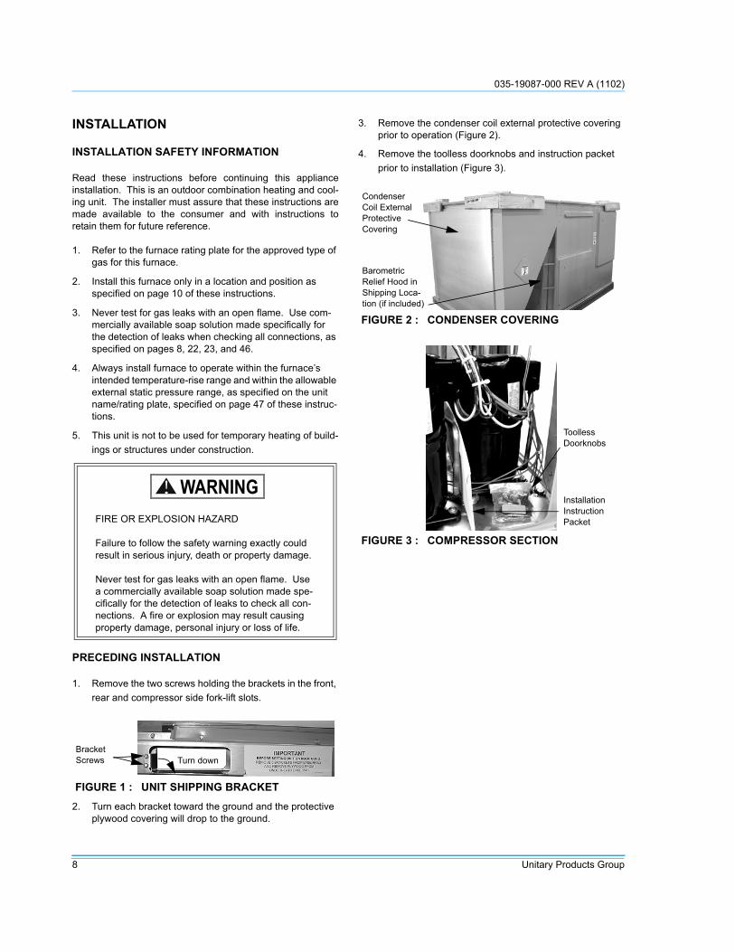
3. Remove the condenser coil external protective covering prior to operation (Figure 2).
4. Remove the toolless doorknobs and instruction packet prior to installation (Figure 3).
FIRE OR EXPLOSION HAZARD
Failure to follow the safety warning exactly could result in serious injury, death or property damage.
Never test for gas leaks with an open flame. Use a commercially available soap solution made spe-cifically for the detection of leaks to check all con-nections. A fire or explosion may result causing property damage, personal injury or loss of life.
FIGURE 1 : UNIT SHIPPING BRACKET
WARNING
BracketScrews Turn down
FIGURE 2 : CONDENSER COVERING
FIGURE 3 : COMPRESSOR SECTION
CondenserCoil ExternalProtectiveCovering
Barometric Relief Hood in Shipping Loca-tion (if included)
ToollessDoorknobs
InstallationInstructionPacket

035-19087-000 REV A (1102)
Unitary Products Group 9
LIMITATIONS
These units must be installed in accordance with the follow-ing:
In U.S.A.:
1. National Electrical Code, ANSI/NFPA No. 70 - Latest Edition
2. National Fuel Gas Code, NFPA 54/ANSI Z223.1 - Latest Edition
3. Gas-Fired Central Furnace Standard, ANSI Z21.47a - Latest Edition
4. Local building codes, and
5. Local gas utility requirements.
In Canada:
1. Canadian Electrical Code, CSA C22.1
2. Installation Codes, CSA - B149.1
3. Local plumbing and waste water codes
4. Other applicable local codes.
Refer to Tables 3 & 4 for unit application data.
After installation, gas fired units must be adjusted to obtain atemperature rise within the range specified on the unit ratingplate.
If components are to be added to a unit to meet local codes,they are to be installed at the dealer’s and/or customer’sexpense.
Size of unit for proposed installation should be based on heatloss/heat gain calculation made according to the methods ofAir Conditioning Contractors of America (ACCA).
This furnace is not to be used for temporary heating of build-ings or structures under construction.
This product must be installed in strict compliance with the enclosed installation instructions and any applicable local, state and national codes includ-ing, but not limited to, building, electrical, and mechanical codes.
The furnace and its individual shut-off valve must be disconnected from the gas supply piping sys-tem during any pressure testing at pressures in excess of 1/2 PSIG.
Pressures greater than 1/2 PSIG will cause gas valve damage resulting in a hazardous condition. If it is subjected to a pressure greater than 1/2 PSIG, the gas valve must be replaced.
The furnace must be isolated from the gas supply piping system by closing its individual manual shut-off valve during any pressure testing of the gas supply piping system at test pressures equal to or less than 1/2 PSIG
CAUTION
035-19087-000 REV A (1102)
10 Unitary Products Group
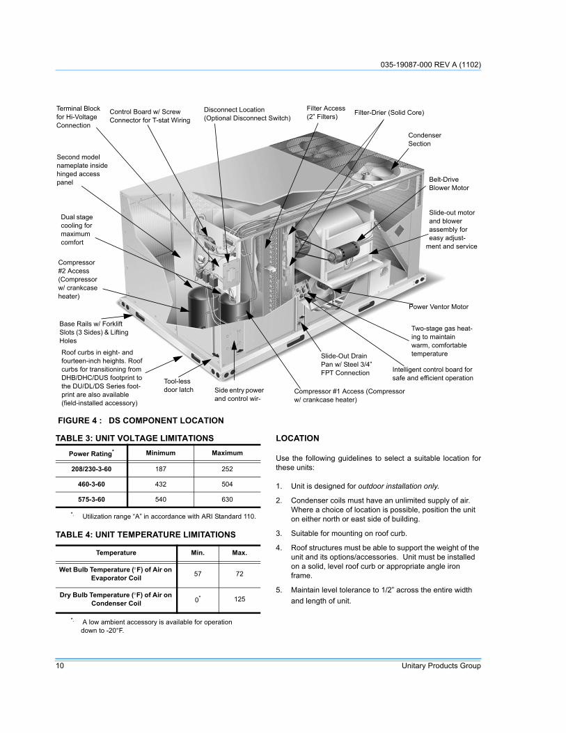
LOCATION
Use the following guidelines to select a suitable location forthese units:
1. Unit is designed for outdoor installation only.
2. Condenser coils must have an unlimited supply of air. Where a choice of location is possible, position the unit on either north or east side of building.
3. Suitable for mounting on roof curb.
4. Roof structures must be able to support the weight of the unit and its options/accessories. Unit must be installed on a solid, level roof curb or appropriate angle iron frame.
5. Maintain level tolerance to 1/2” across the entire width and length of unit.
FIGURE 4 : DS COMPONENT LOCATION
Slide-Out Drain Pan w/ Steel 3/4” FPT Connection
Power Ventor Motor
Compressor #1 Access (Compressor w/ crankcase heater)
Belt-Drive Blower Motor
Terminal Block for Hi-Voltage Connection
Control Board w/ ScrewConnector for T-stat Wiring
Disconnect Location(Optional Disconnect Switch)
Filter Access(2” Filters) Filter-Drier (Solid Core)
Condenser Section
Intelligent control board for safe and efficient operation
Two-stage gas heat-ing to maintain warm, comfortable temperature
Tool-less door latch
Roof curbs in eight- and fourteen-inch heights. Roof curbs for transitioning from DHB/DHC/DUS footprint to the DU/DL/DS Series foot-print are also available (field-installed accessory)
Dual stage cooling for maximum comfort
Second model nameplate inside hinged access panel
Slide-out motor and blower assembly for easy adjust-
ment and service
Base Rails w/ Forklift Slots (3 Sides) & Lifting Holes
Side entry power and control wir-
Compressor #2 Access (Compressor w/ crankcase heater)
TABLE 3: UNIT VOLTAGE LIMITATIONS
Power Rating* Minimum Maximum
208/230-3-60 187 252
460-3-60 432 504
575-3-60 540 630
*. Utilization range “A” in accordance with ARI Standard 110.
TABLE 4: UNIT TEMPERATURE LIMITATIONS
Temperature Min. Max.
Wet Bulb Temperature (°F) of Air on Evaporator Coil 57 72
Dry Bulb Temperature (°F) of Air on Condenser Coil 0* 125
*. A low ambient accessory is available for operation down to -20°F.

035-19087-000 REV A (1102)
Unitary Products Group 11
RIGGING AND HANDLING
Exercise care when moving the unit. Do not remove anypackaging until the unit is near the place of installation. Rigthe unit by attaching chain or cable slings to the lifting holesprovided in the base rails. Spreader bars, whose lengthexceeds the largest dimension across the unit, MUST beused across the top of the unit.
Units may be moved or lifted with a forklift. Slotted openingsin the base rails are provided for this purpose.
LENGTH OF FORKS MUST BE A MINIMUM OF 60INCHES.
Excessive exposure of this furnace to contami-nated combustion air may result in equipment damage or personal injury. Typical contaminates include: permanent wave solution, chlorinated waxes and cleaners, chlorine based swimming pool chemicals, water softening chemicals, carbon tetrachloride, Halogen type refrigerants, cleaning solvents (e. g. perchloroethylene), printing inks, paint removers, varnishes, hydrochloric acid, cements and glues, antistatic fabric softeners for clothes dryers and masonry acid washing materi-als.
If a unit is to be installed on a roof curb other than a Unitary Products roof curb, gasketing must be applied to all surfaces that come in contact with the unit underside.
Before lifting, make sure the unit weight is distrib-uted equally on the rigging cables so it will lift evenly.
WARNING
CAUTION
CAUTION
All panels must be secured in place when the unit is lifted.
The condenser coils should be protected from rig-ging cable damage with plywood or other suitable material.
TABLE 5: UNIT WEIGHTSModel Shipping Weight* (lb.) Operating Weight (lb.)*DS-06 1058 1053
DS-07 1096 1091
DS-08 1150 1145
DS-10 1190 1185
Econ. 85 84
PE 150 148
Gas Heat† 110 100
Elec. Heat‡ 49 49
*. Weights include largest gas heat option.†. 8 tube gas heat section‡. 54kW heater.
FIGURE 5 : UNIT 4 POINT LOAD
TABLE 6: 4 POINT LOAD WEIGHT
ModelLocation (lbs.)*
*. Weights include largest heating option
A B C D
DS-06 231 197 288 337
DS-07 239 204 298 349
DS-08 251 215 313 366
DS-10 260 222 324 379
CAUTION
D
A
CBLEFT
FRONT

035-19087-000 REV A (1102)
12 Unitary Products Group
CLEARANCES
All units require particular clearances for proper operationand service. Installer must make provisions for adequatecombustion and ventilation air in accordance with section 5.3(Air for Combustion and Ventilation) of the National Fuel GasCode, NFPA 54/ANSI Z223.1 – Latest Edition, or Sections7.2, 7.3, or 7.4 of Installation Codes, CSA-B149.1 - LatestEdition, and/or applicable provisions of the local buildingcodes. Refer toTable 8 for clearances required for combusti-ble construction, servicing, and proper unit operation.
NOTE:
A one-inch clearance must be provided between any com-bustible material and the supply ductwork for a distance of 3feet from the unit.
NOTE: If the unit includes gas heating, locate the unit so theflue exhaust is at least:
• Three (3) feet above any forced air inlet located within 10 horizontal feet (excluding those integral to the unit).
• Four (4) feet below, four (4) horizontal feet from, or one (1) foot above any door or gravity air inlet into the build-ing.
• Four (4) feet from electric meters, gas meters, regula-tors, and relief equipment.
.
TABLE 7: 6 POINT LOAD WEIGHT
ModelLocation (lbs.)*
A B C D E F
DS-06 158 142 128 187 207 231
DS-07 164 147 133 194 215 239
DS-08 172 154 139 203 225 251
DS-10 178 160 144 210 233 260
*. Weights include largest heating option
FIGURE 6 : UNIT 6 POINT LOAD
FIGURE 7 : UNIT CENTER OF GRAVITY
D
A
C
BE
F
LEFT
FRONT
F�R�O�N�T�L�E�F�T�
47-1/2" 25-1/2"
Do not permit overhanging structures or shrubs to obstruct condenser air discharge outlet, combus-tion air inlet or vent outlets.
Excessive exposure to contaminated combustion air will result in safety and performance related problems. To maintain combustion air quality, the recommended source of combustion air is the out-door air supply. The outdoor air supplied for com-bustion should be free from contaminants due to chemical exposure that may be present from the following sources.
• Commercial buildings• Indoor pools• Laundry rooms• Hobby or craft rooms• Chemical storage areas
The following substances should be avoided to maintain outdoor combustion air quality.
• Permanent wave solutions• Chlorinated waxes and cleaners• Chlorine based swimming pool cleaners• Water softening chemicals• De-icing salts or chemicals• Carbon tetrachloride• Halogen type refrigerants• Cleaning solvents (such as perchloroethylene)• Printing inks, paint removers, varnishes, etc.• Hydrochloric acid• Cements and glues• Anti-static fabric softeners for clothes dryers• Masonry acid washing materials
WARNING
WARNING

035-19087-000 REV A (1102)
Unitary Products Group 13
.
FIGURE 8 : UNIT DIMENSIONS
See DetailA
For BaserailDimensionsSee Detail B
8927
59
50-3/4
4-1/4
6-3/16
17-3/16
24-3/1630-3/16
ConveniencePower OutletEntryØ 7/8
PowerEntry
Ø 2-1/2
11-1/2
30-11/32
ControlEntryØ 7/8
PowerEntry
Ø 2-1/2
LEFT
FRONTFor DrainDimensionsSee Detail C
TABLE 8: UNIT CLEARANCESTop*
*. Units must be installed outdoors. Overhanging struc-tures or shrubs should not obstruct condenser air dis-charge outlet.
72” Right 12”
Front†
†. The products of combustion must not be allowed to accumulate within a confined space and re-circulate.
36” Left 36”
Rear‡
‡. To remove the slide-out drain pan, a rear clearance of sixty inches is required. If space is unavailable, the drain pan can be removed through the front by separat-ing the corner wall.
36” Bottom**
**. Units may be installed on combustible floors made from wood or class A, B or C roof covering materials.
0”
5-1/4 BasePan17-13/16
View of Wall Across from Coil
Gas Pipe InletDETAIL A
� � � � �
� � � � � �
� � � � DETAIL B
� � �
DETAIL C

035-19087-000 REV A (1102)
14 Unitary Products Group
DUCTWORK
Ductwork should be designed and sized according to themethods in Manual D of the Air Conditioning Contractors ofAmerica (ACCA) or as recommended by any other recog-nized authority such as ASHRAE or SMACNA.
A closed return duct system should be used. This will not pre-clude use of economizers or outdoor fresh air intake. Thesupply and return air duct connections at the unit should bemade with flexible joints to minimize noise.
The supply and return air duct systems should be designedfor the CFM and static pressure requirements of the job.They should NOT be sized to match the dimensions of theduct connections on the unit.
Refer to Figure 9 for bottom air duct openings. Refer to Fig-ure 10 for side air duct openings.
DUCT COVERS
Units are shipped with the side duct openings covered and acovering over the bottom of the unit. For bottom duct applica-tion, no duct cover changes are necessary. For side ductapplication, remove the side duct covers and install over thebottom duct openings. The panels removed from the sideduct connections are designed to be reused by securing eachpanel to its respective downflow opening. Keep in mind thatthe supply panel is installed with the painted surface UP, fac-ing the heat exchanger, while the return panel is installedDOWN, facing the downflow duct opening. The supply panelis secured with a bracket (already in place from the factory)and two screws. It’s a snug fit for the panel when sliding itbetween the heat exchanger and unit bottom, but there isroom. The return panel is secured with four screws.
FIGURE 9 : BOTTOM DUCT OPENINGS (VIEWED FROM ABOVE)

035-19087-000 REV A (1102)
Unitary Products Group 15
FIGURE 10 : REAR DUCT DIMENSIONS
FIGURE 11 : DL/DU/DS ROOF CURB DIMENSIONS
� � � � � � � �
� � � � �
� � � �� � � � �
� � � � � � � �
� � � � � � �
� � � � � �
� � � � �
� � � � �
� � � � �� � �
� � � � � �� � �
� � � � � �
� � � � �
� �
� �
� �
� � �
�
� � � � �
! " � # $ � � % � � � % & ' � # " � % �& ( ) � � % � � ( � � � % & � ! ( "
! " � # $ � � % � � � % & ' � # " � % �& ( " � % " � % � � � % & � ! ( "
* � ( " �
� ! + , �
� # � � $ �
� % � # � "
035-19087-000 REV A (1102)
16 Unitary Products Group
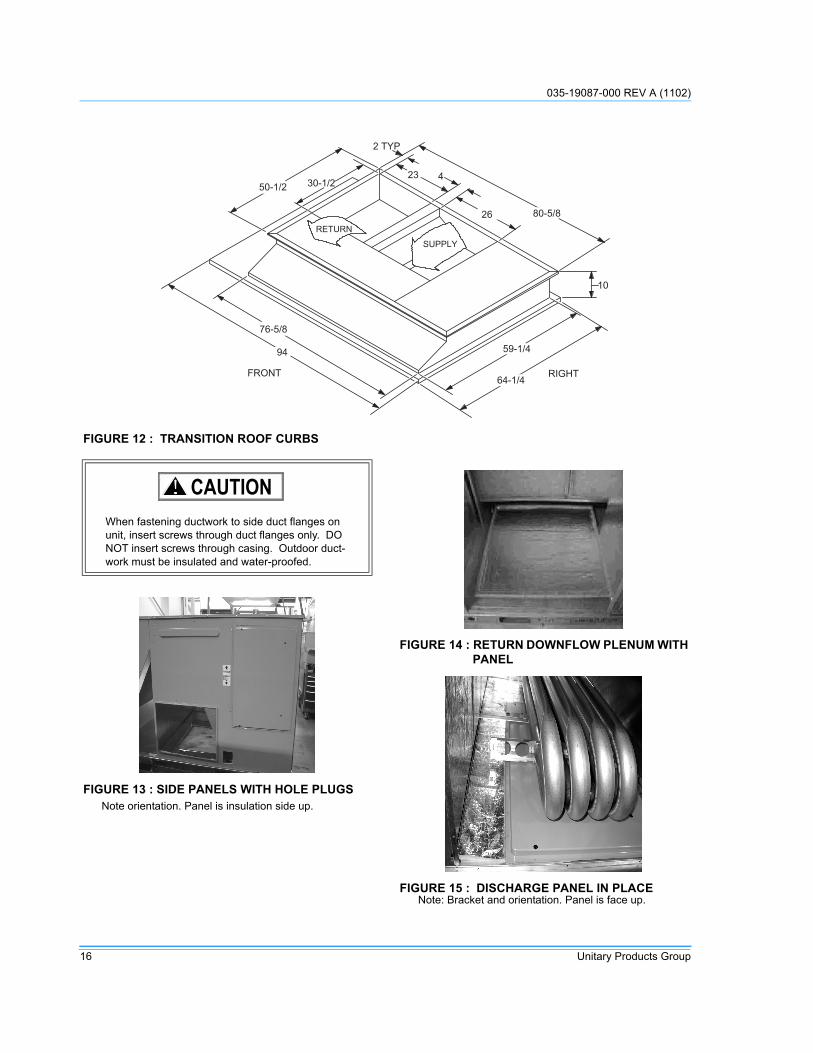
FIGURE 12 : TRANSITION ROOF CURBS
- � � �
� �
� � � � � � � � � � �
� � � � � �
� � � � �
� �
� � �
� � � � �
� � � � �
* � ( " � � ! + , �
� # � � $ �
� % � # � "
When fastening ductwork to side duct flanges on unit, insert screws through duct flanges only. DO NOT insert screws through casing. Outdoor duct-work must be insulated and water-proofed.
FIGURE 13 : SIDE PANELS WITH HOLE PLUGS Note orientation. Panel is insulation side up.
CAUTION
FIGURE 14 : RETURN DOWNFLOW PLENUM WITH PANEL
FIGURE 15 : DISCHARGE PANEL IN PLACENote: Bracket and orientation. Panel is face up.

035-19087-000 REV A (1102)
Unitary Products Group 17
CONDENSATE DRAIN
The side condensate drain is reversible and maybe reorien-tated to the rear of the cabinet to facilitate condensate piping.A condensate drain connection is available through the basepan for piping inside the roof curb. Trap the connection perFigure 16. The trap and drain lines should be protected fromfreezing.
Plumbing must conform to local codes. Use a sealing com-pound on male pipe threads. Install condensate drain linefrom the 3/4 inch NPT female connection on the unit to anopen drain.
COMPRESSORS
The compressors are mounted on elastomer insulators. Themounting bolts have been fully tightened for shipping.
FILTERS
Two-inch filters are supplied with each unit. One-inch filtersmay be used with no modification to the filter racks. Filtersmust always be installed ahead of evaporator coil and mustbe kept clean or replaced with same size and type. Dirty fil-ters reduce the capacity of the unit and result in frosted coilsor safety shutdown. All units use four (4) 20”x25”x2” filters.The unit should not be operated without filters properlyinstalled.
THERMOSTAT WIRING
The thermostat should be located on an inside wall approxi-mately 56 inches above the floor where it will not be sub-jected to drafts, sun exposure or heat from electrical fixturesor appliances. Follow the manufacturer's instructionsenclosed with the thermostat for general installation proce-dure. Seven (7) color-coded, insulated wires should be usedto connect the thermostat to the unit. Refer to Table 9 for con-trol wire sizing and maximum length.
POWER AND CONTROL WIRING
Field wiring to the unit, fuses, and disconnects must conformto provisions of National Electrical Code (NEC), ANSI/NFPA70 – Latest Edition (in U.S.A), current Canadian ElectricCode C221, and/or local ordinances. The unit must be elec-trically grounded in accordance with NEC and CEC as speci-fied above and/or local codes.
Voltage tolerances which must be maintained at the com-pressor terminals during starting and running conditions areindicated on the unit Rating Plate and Table 3.
The internal wiring harnesses furnished with this unit are anintegral part of the design certified unit. Field alteration tocomply with electrical codes should not be required. If any ofthe wire supplied with the unit must be replaced, replacementwire must be of the type shown on the wiring diagram and thesame minimum gauge as the replaced wire.
A disconnect must be utilized for these units. Factoryinstalled disconnects are available. If installing a disconnect(field supplied or Unitary Products supplied accessory),refer to Figure 4 for the recommended mounting location.
FIGURE 16 : CONDENSATE DRAIN
Do not loosen the compressor mounting bolts.
( � � ! ( " � $ � & ( ! $+ # � � �
� . � ) � � � / � /
CAUTION
Make sure that panel latches are properly posi-tioned on the unit to maintain an airtight seal.
TABLE 9: CONTROL WIRE SIZESWire Size Maximum Length*
*. From the unit to the thermostat and back to the unit.
18 AWG 150 Feet
Avoid damage to internal components if drilling holes for disconnect mounting.
CAUTION
CAUTION

035-19087-000 REV A (1102)
18 Unitary Products Group
NOTE: Since not all local codes allow the mounting of a dis-connect on the unit, please confirm compliance with localcode before mounting a disconnect on the unit.
Electrical line must be sized properly to carry the load. USECOPPER CONDUCTORS ONLY. Each unit must be wiredwith a separate branch circuit fed directly from the meterpanel and properly fused.
Refer to Figures 17, 18 and 19 for typical field wiring and tothe appropriate unit wiring diagram mounted inside controldoors for control circuit and power wiring information.
POWER WIRING DETAIL
Units are factory wired for the voltage shown on the unitnameplate. Refer to Electrical Data Tables 10 through 13 tosize power wiring, fuses, and disconnect switch.
Power wiring is brought into the unit through the side of theunit or the basepan inside the curb.
When connecting electrical power and control wir-ing to the unit, water-proof connectors must be used so that water or moisture cannot be drawn into the into the unit during normal operation. The above water-proofing conditions will also apply when installing a field-supplied disconnect switch.
CAUTION
FIGURE 17 : ELECTRONIC THERMOSTAT FIELD WIRING
0 �
� &
� ,
� �
� �
0 �
+
&
1 �
1 �
1 �
� �
� �
�
�
0 �
� �
� �
0 �
+
&
( & &
1
�
� , % � ) ( � � � � �
� % � ) ! " � $ �# " ! � � � % � ) ! " � $ �
� � � ! � � � 2 �
� � % � � 3 � � � � 3 � � � � � � 4 / / 4 5 � � � � 6 � � / � � 4 � � % � � - - � � � � � � � � 7 � � 3 � � 8 � � � � � 5 5 4 � � 9 � � � � � / � � 4 � � � � � � 4 � 8 � � � � � � � : � 8 � � 4 � � � � 4 � � � � � � � � � 3 � � � � � 6 � � � � 8 � � �� � � 3 � � � / � ; � � � 8 4 / � � � � � < 6 � � � 6 � � 6 � � / � � 4 � � < � 3 6 � � � � � 6 � � � � � 5 4 3 = � � � � � � � �
� � � > � � � � 4 � � ? � � / � �
�
� ( � � % ) ( � % � � % " � ( �� % � � � - � � � � � � ! * � # � % �

035-19087-000 REV A (1102)
Unitary Products Group 19
FIGURE 18 : FIELD WIRING 24 VOLT THERMOSTAT
( & &
0 �
0 �
� �
+
� �
1
�
� �
&
�%)(�%
)!"��(�
0 �
0 �
� �
+
� �
&
# " ! � � & ( " � � ( $2 ( � � �
� � � � � �
� ,
� &
FIGURE 19 : FIELD WIRING DISCONNECT
� % � ) ! " � $ � 2 $ ( & ' � � 2 �
+ � ( # " �$ # +
� , � % %� , � � %� ( 0 % �� # � � $ �
* � & � ( � � � ( � � * ! % $ �� # � � $ ! % � � � ! � & ( " " % & �

035-19087-000 REV A (1102)
20 Unitary Products Group
TABLE 10: ELECTRICAL DATA DS 6-1/2 TON
VoltageCompressors
OD Fan
Motors
Supply Blower Motor
Pwr Exh.
MotorFLA
Electric HeaterMinimum
Circuit Ampacity
MCA with Power
Exhaust
Max Fuse* Size
(Amps)
Max Fuse* Size
w/ Pwr.
RLA each
LRA each
FLA each
1.5 HP
2 HP
Model Number
Rated kW
HeaterAmps
1.5 HP 2 HP 1.5
HP 2 HP 1.5 HP
2 HP
1.5 HP
2 HP
208 10.6 78 1.5 6.2 8.2 5.5
None - - 33.1 35.1 38.6 40.6 40 45 45 50
2TP04510925 6.8 18.9 33.1 35.1 38.6 40.7 40 45 45 50
2TP04511825 13.5 37.5 54.6 57.1 61.5 64.0 60 60 70 70
2TP04512425 18.0 50.0 70.2 72.7 77.1 79.6 80 80 80 80
2TP04513625 25.5 70.8 96.2 98.7 103.1 105.6 100 100 110 110
230 10.6 78 1.5 6.2 8.2 5.5
None - - 33.1 35.1 38.6 40.6 40 45 45 50
2TP04510925 9.0 21.7 34.8 37.3 41.7 44.2 40 45 45 50
2TP04511825 18.0 43.3 61.9 64.4 68.8 71.3 70 70 70 80
2TP04512425 24.0 57.7 79.9 82.4 86.8 89.3 80 90 90 90
2TP04513625 34.0 81.8 110.0 112.5 116.9 119.4 110 125 125 125
460 5.2 40 0.8 3.1 4.1 2.2
None - - 16.4 17.4 18.6 19.6 20 20 20 20
2TP04510946 9.0 10.8 17.4 18.7 20.2 21.4 20 20 25 25
2TP04511846 18.0 21.7 30.9 32.2 33.7 34.9 35 35 35 35
2TP04512446 24.0 28.9 40.0 41.2 42.7 44.0 40 45 45 45
2TP04513646 34.0 40.9 55.0 56.2 57.7 59.0 60 60 60 60
575 3.6 32 0.6 2.4 3.6 1.8
None - - 11.7 12.9 13.5 14.7 15 15 15 15
2TP04510958 9.0 8.7 13.8 15.3 16.1 17.6 15 20 20 20
2TP04511858 18.0 17.3 24.7 26.2 26.9 28.4 25 30 30 30
2TP04512458 24.0 23.1 31.9 33.4 34.1 35.6 35 35 35 40
2TP04513658 34.0 32.7 43.9 45.4 46.1 47.6 45 50 50 50
*. Maximum HACR breaker size is applicable.TABLE 11: ELECTRICAL DATA DS 7-1/2 TON
VoltageCompressors
OD Fan
Motors
Supply Blower Motor
Power Exh.
Motor FLA
Electric HeaterMinimum
Circuit Ampacity
MCA with Power
Exhaust
Max Fuse* Size
(Amps)
Max Fuse Size
w/Pwr.
RLA each
LRA each
FLA each
1.5 HP
2 HP
Model Numbers
Rated kW
Heater Amps
1.5 HP 2 HP 1.5
HP 2 HP 1.5 HP
2 HP
1.5 HP
2 HP
208 12.8 110 1.5 6.2 8.2 5.5
None - - 38.0 40.0 43.5 45.5 50 50 50 50
2TP04510925 6.8 18.9 38.0 40.0 43.5 45.5 50 50 50 50
2TP04511825 13.5 37.5 54.6 57.1 61.5 64.0 60 60 70 70
2TP04512425 18 50.0 70.2 72.7 77.1 79.6 80 80 80 80
2TP04513625 25.5 70.8 96.2 98.7 103.1 105.6 100 100 110 110
230 12.8 110 1.5 6.2 8.2 5.5
None - - 38.0 40.0 43.5 45.5 50 50 50 50
2TP04510925 9 21.7 38.0 40.0 43.5 45.5 50 50 50 50
2TP04511825 18 43.3 61.9 64.4 68.8 71.3 70 70 70 80
2TP04512425 24 57.7 79.9 82.4 86.8 89.3 80 90 90 90
2TP04513625 34 81.8 110.0 112.5 116.9 119.4 110 125 125 125
460 7.1 54 0.8 3.1 4.1 2.2
None - - 20.7 21.7 22.9 23.9 25 25 25 30
2TP04510946 9 10.8 20.7 21.7 22.9 23.9 25 25 25 30
2TP04511846 18 21.7 30.9 32.2 33.7 34.9 35 35 35 35
2TP04512446 24 28.9 40.0 41.2 42.7 44.0 40 45 45 45
2TP04513646 34 40.9 55.0 56.2 57.7 59.0 60 60 60 60
575 5.1 44 0.6 2.4 3.6 1.8
None - - 15.1 16.3 16.9 18.1 20 20 20 20
2TP04510958 9 8.7 15.1 16.3 16.9 18.1 20 20 20 20
2TP04511858 18 17.3 24.7 26.2 26.9 28.4 25 30 30 30
2TP04512458 24 23.1 31.9 33.4 34.1 35.6 35 35 35 40
2TP04513658 34 32.7 43.9 45.4 46.1 47.6 45 50 50 50
*. Maximum HACR breaker size is applicable.

035-19087-000 REV A (1102)
Unitary Products Group 21
TABLE 12: ELECTRICAL DATA DS 8-1/2 TON
VoltageCompressors
OD Fan
Motors
Supply Blower
Motor FLAPower Exh.
Motor FLA
Electric HeaterMinimum
Circuit Ampacity
MCA with Power
Exhaust
Max Fuse* Size
(Amps)
Max Fuse* Size
w/Pwr.
RLA each
LRA each
FLA each
2 HP
3 HP
Model Numbers
Rated kW
Heater Amps 2 HP 3 HP 2 HP 3 HP 2
HP3
HP2
HP3
HP
208 13.5 110 1.5 8.2 10.9 5.5
None - - 41.6 44.3 47.1 49.8 50 50 60 60
2TP04510925 6.8 18.9 41.6 44.3 47.1 49.8 50 50 60 60
2TP04511825 13.5 37.5 57.1 60.5 64 67.3 60 70 70 70
2TP04512425 18 50 72.7 76.1 79.6 83 80 80 80 90
2TP04513625 25.5 70.8 98.7 102.1 105.6 109 100 110 110 110
230 13.5 110 1.5 8.2 10.9 5.5
None - - 41.6 44.3 47.1 49.8 50 50 60 60
2TP04510925 9 21.7 41.6 44.3 47.1 49.8 50 50 60 60
2TP04511825 18 43.3 64.4 67.8 71.3 74.6 70 70 80 80
2TP04512425 24 57.7 82.4 85.8 89.3 92.7 90 90 90 100
2TP04513625 34 81.8 112.5 115.9 119.4 122.7 125 125 125 125
460 7.1 54 0.8 4.1 5.3 2.2
None - - 21.7 22.9 23.9 25.1 25 25 30 30
2TP04510946 9 10.8 21.7 22.9 23.9 25.1 25 25 30 30
2TP04511846 18 21.7 32.2 33.7 34.9 36.4 35 35 35 40
2TP04512446 24 28.9 41.2 42.7 44 45.5 45 45 45 50
2TP04513646 34 40.9 56.2 57.7 59 60.5 60 60 60 70
575 5.4 44 0.6 3.6 4.1 1.8
None - - 17 17.5 18.8 19.3 20 20 20 20
2TP04510958 9 8.7 17 17.5 18.8 19.3 20 20 20 20
2TP04511858 18 17.3 26.2 26.8 28.4 29 30 30 30 30
2TP04512458 24 23.1 33.4 34 35.6 36.2 35 35 40 40
2TP04513658 34 32.7 45.4 46 47.6 48.3 50 50 50 50
*. Maximum HACR breaker size is applicable.TABLE 13: ELECTRICAL DATA DS 10 TON
VoltageCompressors
OD Fan
Motors
Supply Blower
Motor FLAPower Exh.
Motor FLA
Electric HeaterMinimum
Circuit Ampacity
MCA with Power
Exhaust
Max Fuse Size
(Amps)
Max Fuse Size
w/Pwr.
RLA each
LRA each
FLA each
2 HP
3 HP
Model Numbers
Rated kW
Heater Amps 2 HP 3 HP 2 HP 3 HP 2
HP3
HP2
HP3
HP
208 16 167 3.5 8.2 10.9 5.5
None - - 51.2 53.9 56.7 59.4 60 60 70 70
2TP04511825 13.5 37.5 57.1 60.5 64 67.3 60 70 70 70
2TP04512425 18 50 72.7 76.1 79.6 83 80 80 80 90
2TP04513625 25.5 70.8 98.7 102.1 105.6 109 100 110 110 110
2TP04515425 40.6 112.7 151.1 154.5 158 161.4 175 175 175 175
230 16 167 3.5 8.2 10.9 5.5
None - - 51.2 53.9 56.7 59.4 60 60 70 70
2TP04511825 18 43.3 64.4 67.8 71.3 74.6 70 70 80 80
2TP04512425 24 57.7 82.4 85.8 89.3 92.7 90 90 90 100
2TP04513625 34 81.8 112.5 115.9 119.4 122.7 125 125 125 125
2TP04515425 54 129.9 140.2 143.5 147 150.4 150 175 150 175
460 8.3 69 1.6 4.1 5.3 2.2
None - - 26 27.2 28.2 29.4 30 35 35 35
2TP04511846 18 21.7 32.2 33.7 34.9 36.4 35 35 35 40
2TP04512446 24 28.9 41.2 42.7 44 45.5 45 45 45 50
2TP04513646 34 40.9 56.2 57.7 59 60.5 60 60 60 70
2TP04515446 54 65 70.1 71.6 72.8 74.3 80 80 80 80
575 6.4 58 1.3 3.6 4.1 1.8
None - - 20.6 21.1 22.4 22.9 25 25 25 25
2TP04511858 18 17.3 26.2 26.8 28.4 29 30 30 30 30
2TP04512458 24 23.1 33.4 34 35.6 36.2 35 35 40 40
2TP04513658 34 32.7 45.4 46 47.6 48.3 50 50 50 50
2TP04515458 54 52 56.5 57.1 58.7 59.3 70 70 70 70

035-19087-000 REV A (1102)
22 Unitary Products Group
OPTIONAL GAS HEAT
These gas fired heaters have aluminized-steel (or optionalstainless steel) tubular heat exchangers with spark ignition.
GAS PIPING
Proper sizing of gas piping depends on the cubic feet perhour of gas flow required, specific gravity of the gas, and thelength of run. “National Fuel Gas Code” NFPA 54/ANSIZ223.1 - Latest Edition (in U.S.A) or the current Gas Installa-tion Code CSA-B149.1 (in Canada) should be followed in allcases unless superseded by local codes or gas companyrequirements. Refer to the Pipe Sizing Table 16. The heatingvalue of the gas may differ with locality. The value should bechecked with the local gas utility. .
NOTE: Maximum capacity of pipe in cubic feet of gas perhour based upon a pressure drop of 0.3 inch W.C. and 0.6specific gravity gas.
NOTE: There may be a local gas utility requirement specify-ing a minimum diameter for gas piping. All units require a 3/4inch pipe connection at the entrance fitting. Line should notbe sized smaller than the entrance fitting size.
TABLE 14: PHYSICAL DATA (DS SERIES)
ComponentModels
-06 -07 -08 -10
EvaporatorBlower
Blower, Centrifugal (Dia. X Wd. in.) 15 x 15 15 x 15 15 x 15 15 x 15
Motor, Standard (HP) 1-1/2 1-1/2 2 2
Motor, Optional (HP) 2 2 3 3
EvaporatorCoil
Rows 3 3 3 4
Fins per Inch 15 15 15 15
Height (in.) 32 32 40 40
Face Area (ft.2 each) 10.6 10.6 13.2 13.2
CondenserFan
(2 per Unit)
Propeller Dia. (in., each) 24 24 24 24
Motor (HP, each) 1/3 1/3 1/3 3/4
CFM, Nominal (each) 3400 3400 3400 4400
CondenserCoil
(2 per unit)
Rows (each) 1 1 2 2
Fins per Inch 20 20 20 20
Height (in., each) 44 44 44 44
Face Area (ft.2 each) 14.5 14.5 14.5 14.5
RefrigerantCharge
System 1 (lb./oz.) 6/12 6/10 10/0 11/1
System 2 (lb./oz.) 6/4 5/14 8/12 11/1
CompressorsQuantity 2 2 2 2
Type Recip Recip Recip Recip
Air FiltersSize (Wd. x Ht. x Thickness in.) 25x20x2 25x20x2 25x20x2 25x20x2
Number Per Unit 4 4 4 4
TABLE 15: GAS HEAT LIMIT SETTINGS# of HX Tubes Main Limit Setting
4 215°F6 195°F8 160°F

035-19087-000 REV A (1102)
Unitary Products Group 23
GAS CONNECTION
The gas supply line can be routed within the space and roofcurb, exiting through the unit’s basepan. Refer to Figure 9 forthe gas piping inlet location. Typical supply piping arrange-ments are shown in Figures 20 and 21. All pipe nipples, fit-tings, and the gas cock are field supplied or may bepurchased in UPG accessory kit #1GP0404.
Gas piping recommendations:
1. A drip leg and a ground joint union must be installed in the gas piping.
2. Where required by local codes, a manual shut-off valve must be installed outside of the unit.
3. Use wrought iron or steel pipe for all gas lines. Pipe dope should be applied sparingly to male threads only.
4. All piping should be cleaned of dirt and scale by ham-mering on the outside of the pipe and blowing out loose particles. Before initial start-up, be sure that all gas lines external to the unit have been purged of air.
5. The gas supply should be a separate line and installed in accordance with all safety codes as prescribed under “Limitations”.
FIGURE 20 : SIDE ENTRY GAS PIPING
FIGURE 21 : BOTTOM ENTRY GAS PIPING
( � � ! ( " � $& ( ! $+ # � � �� , ( 0 "
OPTIONALCOILGUARDSHOWN
TABLE 16: GAS PIPE SIZING - CAPACITY OF PIPELength of Pipe (ft.)
Nominal Iron Pipe Size3/4 in. 1 in. 1-1/4 in.
10 278 520 1050
20 190 350 730
30 152 285 590
40 130 245 500
50 115 215 440
60 105 195 400
70 96 180 370
80 90 170 350
90 84 160 320
100 79 150 305
Natural gas may contain some propane. Propane is an excellent solvent and will quickly dissolve white lead and most standard commercial com-pounds. A special pipe dope must be used when assembling wrought iron or steel pipe. Shellac based compounds such as Gaskolac or Stalastic, and compounds such as Rectorseal #5, Clydes’s or John Crane may be used.
WARNING

035-19087-000 REV A (1102)
24 Unitary Products Group
6. A 1/8-inch NPT plugged tapping, accessible for test gage connection, must be installed immediately upstream of the gas supply connection to the unit.
7. After the gas connections have been completed, open the main shut-off valve admitting normal gas pressure to the mains. Check all joints for leaks with soap solution or other material suitable for the purpose. NEVER USE A FLAME.
LP UNITS, TANKS AND PIPING
All gas heat units are shipped from the factory equipped fornatural gas use only. The unit may be converted in the fieldfor use with LP gas with accessory kit model number1NP0441.
All LP gas equipment must conform to the safety standards ofthe National Fire Protection Association.
For satisfactory operation, LP gas pressure must be 10.5inch W.C. at the unit under full load. Maintaining proper gaspressure depends on three main factors:
1. The vaporization rate which depends on the temperature of the liquid and the “wetted surface” area of the con-tainer(s).
2. The proper pressure regulation. (Two-stage regulation is recommended).
3. The pressure drop in the lines between regulators and between the second stage regulator and the appliance. Pipe size required will depend on the length of the pipe run and the total load of all appliances.
Complete information regarding tank sizing for vaporization,recommended regulator settings, and pipe sizing is availablefrom most regulator manufacturers and LP gas suppliers.
LP gas is an excellent solvent and will quickly dissolve whitelead and most standard commercial compounds. A specialpipe dope must be used when assembling wrought iron orsteel pipe for LP. Shellac base compounds such as Gaskolacor Stalastic, and compounds such as Rectorseal #5, Clyde’s,or John Crane may be used.
Check all connections for leaks using a soap solution.NEVER USE A FLAME.
VENT AND COMBUSTION AIR
Venting slots in the heating compartment access panelremove the need for a combustion air hood. The gas heatflue exhaust is routed through factory installed exhaust pipingwith attached screen. If necessary, a flue exhaust extensionmay be installed at the point of installation.
FIRE OR EXPLOSION HAZARD
Failure to follow the safety warning exactly could result in serious injury, death or property damage.
Never test for gas leaks with an open flame. Use a commercially available soap solution made spe-cifically for the detection of leaks to check all con-nections. A fire or explosion may result causing property damage, personal injury or loss of life.
The furnace and its individual shut-off valve must be disconnected from the gas supply piping sys-tem during any pressure testing at pressures in excess of 1/2 PSIG.
Pressures greater than 1/2 PSIG will cause gas valve damage resulting in a hazardous condition. If it is subjected to a pressure greater than 1/2 PSIG, the gas valve must be replaced.
The furnace must be isolated from the gas supply piping system by closing its individual manual shut-off valve during any pressure testing of the gas supply piping system at test pressures equal to or less than 1/2 PSIG.
Note: Threaded joints should be coated with a sealing compound that is resistant to the action of liquefied petroleum gases. Do not use Teflon tape.
WARNING
CAUTION
WARNING

035-19087-000 REV A (1102)
Unitary Products Group 25
ACCESSORIES/OPTIONS
ELECTRIC HEAT
Electric heaters are available as field installed accessories.Refer to electric heat instructions for installation. These heat-ers mount in the heat compartment with the heating elementsextending into the supply air chamber. All electric heaters arefused and intended for use with single point power supply.
MOTORIZED OUTDOOR DAMPER
The Motorized Outdoor Damper can be a factory installedoption or a field installed accessory. If factory installed, referto the instructions included with the outdoor air hood to com-plete the assembly. Field installed Motorized OutdoorDamper accessories include complete instructions for instal-lation
ECONOMIZER
The economizer can be a factory installed option or a fieldinstalled accessory. If factory installed, refer to the instruc-tions included with the outdoor air hood to complete theassembly. Field installed Economizers include completeinstructions for installation.
There are two Economizer options:
1. Down Flow application with barometric relief hood stan-dard.
2. Horizontal Flow application that requires the purchase of a barometric relief hood.
POWER EXHAUST
The Power Exhaust can be a factory installed option or a fieldinstalled accessory. If factory installed, refer to the instructionincluded with the outdoor air hood to complete the assembly.Field installed Power Exhaust accessories include completeinstructions for installation.
The power exhaust factory installed option is for Down Flowapplication only.
There are two field installed Power exhaust accessories:
1. Down Flow application.
2. Horizontal Flow application that requires the purchase of a barometric relief hood.
RAIN HOOD
All of the hood components, including the filters, the gasket-ing, and the hardware for assembling, are packaged andlocated between the condenser coil section and the main unitcabinet, if the unit has been ordered with the option. If fieldinstalled, instructions detailing rain hood assembly areincluded with the accessory.
ECONOMIZER AND POWER EXHAUST SET POINT ADJUSTMENTS AND INFORMATION
Remove the top rear panel from the unit. Locate the econo-mizer control module, where the following adjustments will bemade.
MINIMUM POSITION ADJUSTMENT
• Check that the damper blades move smoothly without binding. Carefully turn the Minimum Position Adjustment screw (found on the damper control module) fully clock-wise and then set the thermostat indoor fan switch to the ON position and then to the OFF position (or energize and de-energize terminals “R” to “G”).
• With the thermostat set to the indoor fan ON position (or terminals “R” to “G” energized), turn the Minimum Posi-tion Adjustment screw counterclockwise until the desired minimum damper position has been attained.
ENTHALPY SET POINT ADJUSTMENT
The enthalpy set point for the dampers may now be set byselecting the desired set point shown in Figure 22. Adjust asfollows:
• For single enthalpy operation, carefully turn the set point adjusting screw to the “A”, “B”, “C” or “D” setting corre-sponding to the lettered curve representing the desired set point.
• For dual enthalpy operation, carefully turn the set point adjusting screw fully clockwise past the “D” setting.
POWER EXHAUST DAMPER SET POINT (WITH OR WITH-OUT POWER EXHAUST)
• With no power exhaust option, adjust the Exhaust Air Adjustment screw fully clockwise. This will allow 2nd stage cooling to operate.
Extreme care must be exercised in turning the set-point, maximum and minimum position adjusting screws to prevent twisting them off.
CAUTION

035-19087-000 REV A (1102)
26 Unitary Products Group
• On units equipped with a power exhaust, each building pressurization requirement will be different. The point at which the power exhaust comes on is determined by the economizer damper position (Percent Open). The exhaust Air Adjustment screw should be set at the Per-cent Open setting of the economizer damper at which the power exhaust is needed. It can be set from 0 to 100% damper open.
INDOOR AIR QUALITY (IAQ)
Indoor Air Quality (indoor sensor input): Terminal AQ acceptsa +2 to +10 Vdc signal with respect to the AQ1 terminal.When the signal is below it’s set point, the actuator is allowedto modulate normally in accordance with the enthalpy andmixed air sensor inputs. When the AQ signal exceeds it’s setpoint setting and there is no call for free cooling, the actuator
is proportionately modulated from the 2 to 10 Vdc signal, with2 Vdc corresponding to full closed and 10 Vdc correspondingto full open. When there is no call for free cooling, thedamper position is limited by the IAQ Max damper positionsetting. When the signal exceeds it’s set point (DemandControl Ventilation Set Point) and there is a call for free cool-ing, the actuator modulates from the minimum position to thefull open position based on the highest call from either themixed air sensor input or the AQ voltage input.
• Optional CO2 Space Sensor kit Part # 2AQ04700324
• Optional CO2 Sensor Kit Part # 2AQ04700424
Replace the top rear access panel on the unit.
FIGURE 22 : ENTHALPY SET POINT CHART

035-19087-000 REV A (1102)
Unitary Products Group 27
PHASING
These units are properly phased at the factory. Check forproper indoor blower rotation. If the indoor blower rotates inthe wrong direction at start-up, the electrical connection to theunit is misphased. Change the phasing at the field powerline connection located at the unit disconnect to obtainproper rotation.
FIGURE 23 : HONEYWELL ECONOMIZER CONTROL W7212
TABLE 17: SUPPLY AIR LIMITATIONSUnit Size Minimum Maximum
-06 1950 3250
-07 2250 3750
-08 2550 4250
-10 3000 5000

035-19087-000 REV A (1102)
28 Unitary Products Group
BELT TENSION
The tension on the belt should be adjusted as shown in Fig-ure 24.
FIGURE 24 : BELT ADJUSTMENT
A
A
A
B
SPAN LENGTH
DEFL. FORCE
C** NEVER LOOSEN
Procedure for adjusting belt tension:
1. Loosen six nuts (top and bottom) A.2. Adjust by turning (B).3. Never loosen nuts (C).4. Use belt tension checker to apply a perpendicular force to one belt at the midpoint of the span as shown. Deflection distance of 4mm (5/32”) is obtained.To determine the deflection distance from normal position, use a straight edge from sheave to sheave as reference line. The recommended deflection force is as follows:
Tension new belts at the max. deflection force rec-ommended for the belt section. Check the belt tension at least two times during the first 24 hours of operation. Any retensioning should fall between the min. and max. deflection force values.
5. After adjusting retighten nuts (A).
CAUTION

035-19087-000 REV A (1102)
Unitary Products Group 29
TABLE 18: 6-1/2 TON STANDARD MOTOR DOWN SHOT BLOWER PERFORMANCE* †
ESP‡
TURNS OPEN**
0 1 2 3 4 5
CFM W†† BHP CFM W†† BHP CFM W†† BHP CFM W†† BHP CFM W†† BHP CFM W†† BHP
0.2 - - - - - - 3291 1191 1.28 3096 1059 1.14 2963 948 1.02 2757 831 0.89
0.4 - - - 3168 1225 1.31 2969 1085 1.16 2658 939 1.01 2535 834 0.89 2255 718 0.77
0.6 3223 1273 1.37 2732 1084 1.16 2500 947 1.02 2110 803 0.86 1923 699 0.75 1608 596 0.64
0.8 2541 1091 1.17 2168 925 0.99 1882 793 0.85 - - - - - - - - -
1.0 1859 908 0.97 - - - - - - - - - - - - - - -
*. Blower performance for gas heat includes maximum number of heat tubes available for each tonnage.†. Blower performance includes two-inch throwaway filters.‡. ESP (External Static Pressure) given is that available for the supply and return air duct system. All internal resistances have been
deducted from the total static pressure of the blower.**. “Turns Open” refers to the setting of the variable pitch motor sheave, where “0 Turns Open” is fully closed.††. W = Watts
TABLE 19: 6-1/2 TON OPTIONAL MOTOR DOWN SHOT BLOWER PERFORMANCE* †
ESP‡
TURNS OPEN**
0 1 2 3 4 5
CFM W†† BHP CFM W†† BHP CFM W†† BHP CFM W†† BHP CFM W†† BHP CFM W†† BHP
0.4 - - - - - - - - - - - - - - - 3489 1553 1.67
0.6 - - - - - - - - - - - - 3394 1641 1.76 3101 1407 1.51
0.8 - - - - - - 3623 2009 2.15 3323 1742 1.87 2971 1477 1.58 2607 1241 1.33
1.0 - - - 3643 2150 2.31 3224 1820 1.95 2889 1569 1.68 2466 1306 1.40 2009 1071 1.15
1.2 3613 2238 2.40 3143 1917 2.06 2748 1621 1.74 2369 1385 1.49 1879 1141 1.22 - - -
1.4 3099 2039 2.19 2636 1711 1.83 2195 1424 1.53 - - - - - - - - -
1.6 2586 1833 1.97 2124 1532 1.64 - - - - - - - - - - - -
1.8 2073 1621 1.74 - - - - - - - - - - - - - - -
*. Blower performance for gas heat includes maximum number of heat tubes available for each tonnage.†. Blower performance includes two-inch throwaway filters.‡. ESP (External Static Pressure) given is that available for the supply and return air duct system. All internal resistances have been
deducted from the total static pressure of the blower.**. “Turns Open” refers to the setting of the variable pitch motor sheave, where “0 Turns Open” is fully closed.††. W = Watts

035-19087-000 REV A (1102)
30 Unitary Products Group
TABLE 20: 7-1/2 TON STANDARD MOTOR DOWN SHOT BLOWER PERFORMANCE* †
ESP‡
TURNS OPEN**
0 1 2 3 4 5
CFM W†† BHP CFM W†† BHP CFM W†† BHP CFM W†† BHP CFM W†† BHP CFM W†† BHP
0.2 - - - 3715 1573 1.69 3634 1434 1.54 3431 1265 1.36 3218 901 0.97 3024 976 1.05
0.4 3650 1657 1.78 3510 1490 1.60 3320 1313 1.41 3079 1145 1.23 2832 810 0.87 2586 860 0.92
0.6 3334 1522 1.63 3146 1351 1.45 2910 1169 1.25 2621 1005 1.08 2307 706 0.76 - - -
0.8 2903 1352 1.45 2622 1167 1.25 2404 1013 1.09 2054 858 0.92 - - - - - -
1.0 2356 1159 1.24 - - - - - - - - - - - - - - -
*. Blower performance for gas heat includes maximum number of heat tubes available for each tonnage.†. Blower performance includes two-inch throwaway filters.‡. ESP (External Static Pressure) given is that available for the supply and return air duct system. All internal resistances have been
deducted from the total static pressure of the blower.**. “Turns Open” refers to the setting of the variable pitch motor sheave, where “0 Turns Open” is fully closed.††. W = Watts
TABLE 21: 7-1/2 TON OPTIONAL MOTOR DOWN SHOT BLOWER PERFORMANCE* †
ESP‡
TURNS OPEN**
0 1 2 3 4 5
CFM W†† BHP CFM W†† BHP CFM W†† BHP CFM W†† BHP CFM W†† BHP CFM W†† BHP
0.2 - - - - - - - - - - - - 3992 1904 2.04 3798 1679 1.80
0.4 - - - - - - - - - 3930 2017 2.16 3734 1786 1.92 3486 1552 1.66
0.6 - - - - - - 3947 2176 2.33 3670 1895 2.03 3394 1641 1.76 3084 1401 1.50
0.8 - - - 4138 2384 2.56 3623 2009 2.15 3323 1742 1.87 2971 1477 1.58 2591 1236 1.33
1.0 4126 2430 2.61 3643 2145 2.30 3224 1820 1.95 2889 1569 1.68 2466 1306 1.40 - - -
1.2 3613 2238 2.40 3143 1921 2.06 2748 1621 1.74 2369 1385 1.49 - - - - - -
1.4 3099 2039 2.19 2636 1714 1.84 2195 1424 1.53 - - - - - - - - -
1.6 2586 1833 1.97 - - - - - - - - - - - - - - -
*. Blower performance for gas heat includes maximum number of heat tubes available for each tonnage.†. Blower performance includes two-inch throwaway filters.‡. ESP (External Static Pressure) given is that available for the supply and return air duct system. All internal resistances have been
deducted from the total static pressure of the blower.**. “Turns Open” refers to the setting of the variable pitch motor sheave, where “0 Turns Open” is fully closed.††. W = Watts

035-19087-000 REV A (1102)
Unitary Products Group 31
TABLE 22: 8-1/2 TON STANDARD MOTOR DOWN SHOT BLOWER PERFORMANCE* †
ESP‡
TURNS OPEN**
0 1 2 3 4 5
CFM W†† BHP CFM W†† BHP CFM W†† BHP CFM W†† BHP CFM W†† BHP CFM W†† BHP
0.2 - - - 4090 1816 1.95 3872 1613 1.73 3681 1448 1.55 3420 1271 1.36 3217 1125 1.21
0.4 3783 1778 1.91 3782 1685 1.81 3548 1489 1.60 3334 1325 1.42 3026 1149 1.23 2796 1010 1.08
0.6 3648 1720 1.84 3387 1529 1.64 3123 1340 1.44 2874 1176 1.26 2495 1002 1.08 - - -
0.8 3317 1583 1.70 2903 1354 1.45 2599 1175 1.26 - - - - - - - - -
1.0 2788 1385 1.49 - - - - - - - - - - - - - - -
*. Blower performance for gas heat includes maximum number of heat tubes available for each tonnage.†. Blower performance includes two-inch throwaway filters.‡. ESP (External Static Pressure) given is that available for the supply and return air duct system. All internal resistances have been
deducted from the total static pressure of the blower.**. “Turns Open” refers to the setting of the variable pitch motor sheave, where “0 Turns Open” is fully closed.††. W = Watts
TABLE 23: 8-1/2 TON OPTIONAL MOTOR DOWN SHOT BLOWER PERFORMANCE* †
ESP‡
TURNS OPEN**
0 1 2 3 4 5
CFM W†† BHP CFM W†† BHP CFM W†† BHP CFM W†† BHP CFM W†† BHP CFM W†† BHP
0.4 - - - - - - - - - 4257 2325 2.49 4117 2079 2.23 3878 1816 1.95
0.6 - - - - - - 4363 2596 2.78 4114 2248 2.41 3876 1961 2.10 3556 1676 1.80
0.8 - - - 4323 2776 2.98 4107 2446 2.62 3838 2104 2.26 3499 1788 1.92 3166 1520 1.63
1.0 4317 2968 3.18 4175 2677 2.87 3803 2276 2.44 3427 1905 2.04 2987 1577 1.69 2710 1355 1.45
1.2 4243 2918 3.13 3869 2486 2.67 3451 2089 2.24 2882 1669 1.79 - - - - - -
1.4 3977 2743 2.94 3408 2225 2.39 3051 1888 2.03 - - - - - - - - -
1.6 3518 2467 2.65 2790 1927 2.07 2604 1679 1.80 - - - - - - - - -
1.8 2868 2125 2.28 - - - - - - - - - - - - - - -
*. Blower performance for gas heat includes maximum number of heat tubes available for each tonnage.†. Blower performance includes two-inch throwaway filters.‡. ESP (External Static Pressure) given is that available for the supply and return air duct system. All internal resistances have been
deducted from the total static pressure of the blower.**. “Turns Open” refers to the setting of the variable pitch motor sheave, where “0 Turns Open” is fully closed.††. W = Watts

035-19087-000 REV A (1102)
32 Unitary Products Group
TABLE 24: 10 TON STANDARD MOTOR DOWN SHOT BLOWER PERFORMANCE* †
ESP‡
TURNS OPEN**
0 1 2 3 4 5
CFM W†† BHP CFM W†† BHP CFM W†† BHP CFM W†† BHP CFM W†† BHP CFM W†† BHP
0.2 - - - - - - - - - 3896 1639 1.76 3688 1453 1.56 3447 1268 1.36
0.4 4040 2076 2.23 4005 1934 2.07 3790 1698 1.82 3569 1508 1.62 3333 1330 1.43 3057 1147 1.23
0.6 3890 2006 2.15 3697 1790 1.92 3427 1550 1.66 3152 1356 1.45 - - - - - -
0.8 3620 1882 2.02 3324 1629 1.75 2972 1380 1.48 - - - - - - - - -
1.0 3227 1708 1.83 - - - - - - - - - - - - - - -
*. Blower performance for gas heat includes maximum number of heat tubes available for each tonnage.†. Blower performance includes two-inch throwaway filters.‡. ESP (External Static Pressure) given is that available for the supply and return air duct system. All internal resistances have been
deducted from the total static pressure of the blower.**. “Turns Open” refers to the setting of the variable pitch motor sheave, where “0 Turns Open” is fully closed.††. W = Watts
TABLE 25: 10 TON OPTIONAL MOTOR DOWN SHOT BLOWER PERFORMANCE* †
ESP‡
TURNS OPEN**
0 1 2 3 4 5
CFM W†† BHP CFM W†† BHP CFM W†† BHP CFM W†† BHP CFM W†† BHP CFM W†† BHP
0.4 4965 3485 3.74 4875 3150 3.38 4613 2739 2.94 4322 2374 2.55 4156 2106 2.26 3907 1860 1.99
0.6 4876 3416 3.66 4651 2997 3.21 4359 2582 2.77 4038 2220 2.38 3860 1966 2.11 3590 1724 1.85
0.8 4713 3291 3.53 4387 2823 3.03 4077 2417 2.59 3719 2059 2.21 3541 1827 1.96 3242 1584 1.70
1.0 4476 3116 3.34 4084 2632 2.82 3768 2245 2.41 3365 1892 2.03 3197 1691 1.81 - - -
1.2 4165 2898 3.11 3741 2427 2.60 3432 2070 2.22 - - - - - - - - -
1.4 3779 2646 2.84 3359 2212 2.37 3069 1895 2.03 - - - - - - - - -
1.6 3319 2372 2.54 - - - - - - - - - - - - - - -
*. Blower performance for gas heat includes maximum number of heat tubes available for each tonnage.†. Blower performance includes two-inch throwaway filters.‡. ESP (External Static Pressure) given is that available for the supply and return air duct system. All internal resistances have been
deducted from the total static pressure of the blower.**. “Turns Open” refers to the setting of the variable pitch motor sheave, where “0 Turns Open” is fully closed.††. W = Watts
035-19087-000 REV A (1102)
Unitary Products Group 33
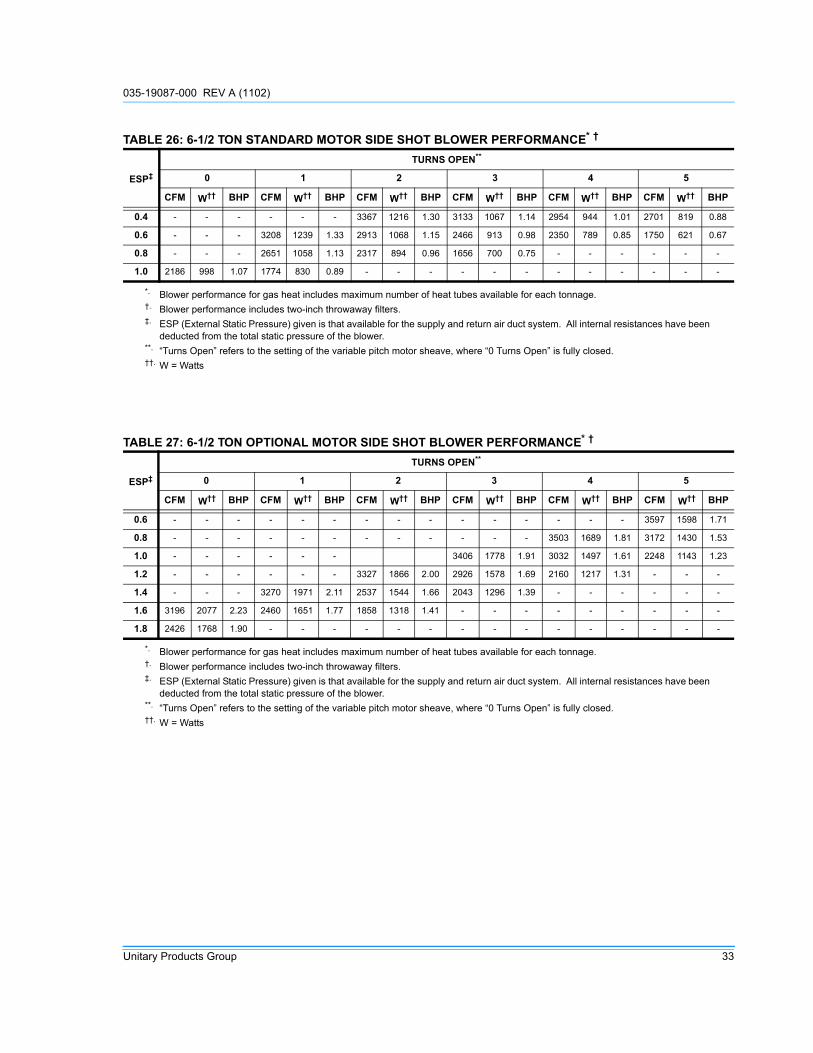
TABLE 26: 6-1/2 TON STANDARD MOTOR SIDE SHOT BLOWER PERFORMANCE* †
ESP‡
TURNS OPEN**
0 1 2 3 4 5
CFM W†† BHP CFM W†† BHP CFM W†† BHP CFM W†† BHP CFM W†† BHP CFM W†† BHP
0.4 - - - - - - 3367 1216 1.30 3133 1067 1.14 2954 944 1.01 2701 819 0.88
0.6 - - - 3208 1239 1.33 2913 1068 1.15 2466 913 0.98 2350 789 0.85 1750 621 0.67
0.8 - - - 2651 1058 1.13 2317 894 0.96 1656 700 0.75 - - - - - -
1.0 2186 998 1.07 1774 830 0.89 - - - - - - - - - - - -
*. Blower performance for gas heat includes maximum number of heat tubes available for each tonnage.†. Blower performance includes two-inch throwaway filters.‡. ESP (External Static Pressure) given is that available for the supply and return air duct system. All internal resistances have been
deducted from the total static pressure of the blower.**. “Turns Open” refers to the setting of the variable pitch motor sheave, where “0 Turns Open” is fully closed.††. W = Watts
TABLE 27: 6-1/2 TON OPTIONAL MOTOR SIDE SHOT BLOWER PERFORMANCE* †
ESP‡
TURNS OPEN**
0 1 2 3 4 5
CFM W†† BHP CFM W†† BHP CFM W†† BHP CFM W†† BHP CFM W†† BHP CFM W†† BHP
0.6 - - - - - - - - - - - - - - - 3597 1598 1.71
0.8 - - - - - - - - - - - - 3503 1689 1.81 3172 1430 1.53
1.0 - - - - - - 3406 1778 1.91 3032 1497 1.61 2248 1143 1.23
1.2 - - - - - - 3327 1866 2.00 2926 1578 1.69 2160 1217 1.31 - - -
1.4 - - - 3270 1971 2.11 2537 1544 1.66 2043 1296 1.39 - - - - - -
1.6 3196 2077 2.23 2460 1651 1.77 1858 1318 1.41 - - - - - - - - -
1.8 2426 1768 1.90 - - - - - - - - - - - - - - -
*. Blower performance for gas heat includes maximum number of heat tubes available for each tonnage.†. Blower performance includes two-inch throwaway filters.‡. ESP (External Static Pressure) given is that available for the supply and return air duct system. All internal resistances have been
deducted from the total static pressure of the blower.**. “Turns Open” refers to the setting of the variable pitch motor sheave, where “0 Turns Open” is fully closed.††. W = Watts

035-19087-000 REV A (1102)
34 Unitary Products Group
TABLE 28: 7-1/2 TON STANDARD MOTOR SIDE SHOT BLOWER PERFORMANCE* †
ESP‡
TURNS OPEN**
0 1 2 3 4 5
CFM W†† BHP CFM W†† BHP CFM W†† BHP CFM W†† BHP CFM W†† BHP CFM W†† BHP
0.4 - - - - - - 3736 1476 1.58 3487 1284 1.38 3231 1109 1.19 3001 970 1.04
0.6 - - - 3572 1514 1.62 3389 1339 1.44 3094 1151 1.23 2764 972 1.04 2446 824 0.88
0.8 3422 1558 1.67 3179 1364 1.46 2889 1164 1.25 2554 985 1.06 - - - - - -
1.0 2891 1347 1.44 2372 1088 1.17 2050 922 0.99 - - - - - - - - -
1.2 2017 1051 1.13 - - - - - - - - - - - - - - -
*. Blower performance for gas heat includes maximum number of heat tubes available for each tonnage.†. Blower performance includes two-inch throwaway filters.‡. ESP (External Static Pressure) given is that available for the supply and return air duct system. All internal resistances have
been deducted from the total static pressure of the blower.**. “Turns Open” refers to the setting of the variable pitch motor sheave, where “0 Turns Open” is fully closed.††. W = Watts
TABLE 29: 7-1/2 TON OPTIONAL MOTOR SIDE SHOT BLOWER PERFORMANCE* †
ESP‡
TURNS OPEN**
0 1 2 3 4 5
CFM W†† BHP CFM W†† BHP CFM W†† BHP CFM W†† BHP CFM W†† BHP CFM W†† BHP
0.4 - - - - - - - - - - - - - - - 3910 1726 1.85
0.6 - - - - - - - - - - - - 3857 1842 1.98 3597 1430 1.53
0.8 - - - - - - - - - 3804 1957 2.10 3503 1689 1.81 3172 1430 1.53
1.0 - - - - - - 3774 2088 2.24 3406 1778 1.91 3032 1497 1.61 2248 1143 1.23
1.2 - - - - - - 3327 1866 2.00 2926 1578 1.69 2160 1217 1.31 - - -
1.4 - - - 3270 1971 2.11 2537 1544 1.66 2043 1296 1.39 - - - - - -
1.6 3196 2077 2.23 2460 1651 1.77 - - - - - - - - - - - -
1.8 2426 1768 1.90 - - - - - - - - - - - - - - -
*. Blower performance for gas heat includes maximum number of heat tubes available for each tonnage.†. Blower performance includes two-inch throwaway filters.‡. ESP (External Static Pressure) given is that available for the supply and return air duct system. All internal resistances have been
deducted from the total static pressure of the blower.**. “Turns Open” refers to the setting of the variable pitch motor sheave, where “0 Turns Open” is fully closed.††. W = Watts

035-19087-000 REV A (1102)
Unitary Products Group 35
TABLE 30: 8-1/2 TON STANDARD MOTOR SIDE SHOT BLOWER PERFORMANCE * †
ESP‡
TURNS OPEN**
0 1 2 3 4 5
CFM W†† BHP CFM W†† BHP CFM W†† BHP CFM W†† BHP CFM W†† BHP CFM W†† BHP
0.4 - - - 4220 1873 2.01 3991 1659 1.78 3745 1468 1.57 3470 1283 1.38 3209 1120 1.20
0.6 - - - 3887 1729 1.85 3612 1514 1.62 3357 1330 1.43 3013 1146 1.23 2719 992 1.06
0.8 - - - 3516 1584 1.70 3219 1372 1.47 2903 2903 3.11 2343 966 1.04 - - -
1.0 3383 1614 1.73 3023 1391 1.49 2557 1161 1.25 - - - - - - - - -
1.2 2674 1341 1.44 - - - - - - - - - - - - - - -
*. Blower performance for gas heat includes maximum number of heat tubes available for each tonnage.†. Blower performance includes two-inch throwaway filters.‡. ESP (External Static Pressure) given is that available for the supply and return air duct system. All internal resistances have been
deducted from the total static pressure of the blower.**. “Turns Open” refers to the setting of the variable pitch motor sheave, where “0 Turns Open” is fully closed.††. W = Watts
TABLE 31: 8-1/2 TON OPTIONAL MOTOR SIDE SHOT BLOWER PERFORMANCE* †
ESP‡
TURNS OPEN**
0 1 2 3 4 5
CFM W†† BHP CFM W†† BHP CFM W†† BHP CFM W†† BHP CFM W†† BHP CFM W†† BHP
0.6 - - - - - - - - - - - - - - - 4068 1902 2.04
0.8 - - - - - - - - - 4306 2348 2.52 4036 2050 2.20 3692 1742 1.87
1.0 - - - - - - 4323 2579 2.77 3967 2172 2.33 3632 1848 1.98 3270 1552 1.66
1.2 - - - - - - 4002 2389 2.56 3613 1996 2.14 3080 1613 1.73 2564 1307 1.40
1.4 - - - 4097 2632 2.82 3691 2210 2.37 2980 1706 1.83 - - - - - -
1.6 4211 2896 3.11 3571 2313 2.48 3003 1869 2.00 - - - - - - - - -
1.8 3776 2623 2.81 2591 1849 1.98 - - - - - - - - - - - -
2.0 2674 2038 2.19 - - - - - - - - - - - - - - -
*. Blower performance for gas heat includes maximum number of heat tubes available for each tonnage.†. Blower performance includes two-inch throwaway filters.‡. ESP (External Static Pressure) given is that available for the supply and return air duct system. All internal resistances have been
deducted from the total static pressure of the blower.**. “Turns Open” refers to the setting of the variable pitch motor sheave, where “0 Turns Open” is fully closed.††. W = Watts

035-19087-000 REV A (1102)
36 Unitary Products Group
TABLE 32: 10 TON STANDARD MOTOR SIDE SHOT BLOWER PERFORMANCE* †
ESP‡
TURNS OPEN**
0 1 2 3 4 5
CFM W†† BHP CFM W†† BHP CFM W†† BHP CFM W†† BHP CFM W†† BHP CFM W†† BHP
0.2 - - - - - - - - - 4368 1843 1.98 4132 1624 1.74 3870 1423 1.53
0.4 - - - 4515 2192 2.35 4213 1885 2.02 4020 1692 1.81 3791 1491 1.60 3499 1283 1.38
0.6 - - - 4192 2027 2.17 3905 1741 1.87 3657 1537 1.65 3383 1345 1.44 3062 1149 1.23
0.8 - - - 3838 1858 1.99 3534 1591 1.71 3236 1386 1.49 2934 1202 1.29 - - -
1.0 3755 1942 2.08 3489 1695 1.82 3081 1425 1.53 - - - - - - - - -
1.2 3337 1757 1.88 2918 1475 1.58 - - - - - - - - - - - -
*. Blower performance for gas heat includes maximum number of heat tubes available for each tonnage.†. Blower performance includes two-inch throwaway filters.‡. ESP (External Static Pressure) given is that available for the supply and return air duct system. All internal resistances have been
deducted from the total static pressure of the blower.**. “Turns Open” refers to the setting of the variable pitch motor sheave, where “0 Turns Open” is fully closed.††. W = Watts
TABLE 33: 10 TON OPTIONAL MOTOR SIDE SHOT BLOWER PERFORMANCE* †
ESP‡
TURNS OPEN**
0 1 2 3 4 5
CFM W†† BHP CFM W†† BHP CFM W†† BHP CFM W†† BHP CFM W†† BHP CFM W†† BHP
0.2 - - - - - - - - - - - - 5067 2614 2.80 4809 2290 2.46
0.4 - - - - - - 5179 3112 3.34 4884 2703 2.90 4729 2401 2.57 4459 2113 2.27
0.6 - - - - - - 4925 2943 3.16 4585 2521 2.70 4429 2244 2.41 4137 1964 2.11
0.8 - - - 4974 3220 3.45 4607 2727 2.92 4267 2342 2.51 4099 2080 2.23 3783 1809 1.94
1.0 4975 3453 3.70 4657 2995 3.21 4305 2550 2.73 3941 2171 2.33 3751 1919 2.06 3371 1630 1.75
1.2 4679 3423 3.67 4366 2808 3.01 4022 2373 2.54 3545 1978 2.12 3305 1741 1.87 - - -
1.4 4429 3065 3.29 4040 2607 2.80 3669 2673 2.87 2918 1700 1.82 - - - - - -
1.6 4107 2845 3.05 3620 2357 2.53 2931 1830 1.96 - - - - - - - - -
1.8 3553 2500 2.68 2756 1899 2.04 - - - - - - - - - - - -
2.0 2439 1939 2.08 - - - - - - - - - - - - - - -
*. Blower performance for gas heat includes maximum number of heat tubes available for each tonnage.†. Blower performance includes two-inch throwaway filters.‡. ESP (External Static Pressure) given is that available for the supply and return air duct system. All internal resistances have been
deducted from the total static pressure of the blower.**. “Turns Open” refers to the setting of the variable pitch motor sheave, where “0 Turns Open” is fully closed.††. W = Watts
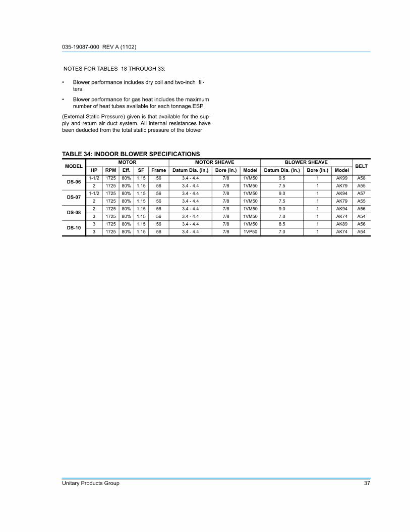
035-19087-000 REV A (1102)
Unitary Products Group 37
NOTES FOR TABLES 18 THROUGH 33:
• Blower performance includes dry coil and two-inch fil-ters.
• Blower performance for gas heat includes the maximum number of heat tubes available for each tonnage.ESP
(External Static Pressure) given is that available for the sup-ply and return air duct system. All internal resistances havebeen deducted from the total static pressure of the blower
TABLE 34: INDOOR BLOWER SPECIFICATIONS
MODELMOTOR MOTOR SHEAVE BLOWER SHEAVE
BELTHP RPM Eff. SF Frame Datum Dia. (in.) Bore (in.) Model Datum Dia. (in.) Bore (in.) Model
DS-061-1/2 1725 80% 1.15 56 3.4 - 4.4 7/8 1VM50 9.5 1 AK99 A58
2 1725 80% 1.15 56 3.4 - 4.4 7/8 1VM50 7.5 1 AK79 A55
DS-071-1/2 1725 80% 1.15 56 3.4 - 4.4 7/8 1VM50 9.0 1 AK94 A57
2 1725 80% 1.15 56 3.4 - 4.4 7/8 1VM50 7.5 1 AK79 A55
DS-082 1725 80% 1.15 56 3.4 - 4.4 7/8 1VM50 9.0 1 AK94 A563 1725 80% 1.15 56 3.4 - 4.4 7/8 1VM50 7.0 1 AK74 A54
DS-103 1725 80% 1.15 56 3.4 - 4.4 7/8 1VM50 8.5 1 AK89 A563 1725 80% 1.15 56 3.4 - 4.4 7/8 1VP50 7.0 1 AK74 A54

035-19087-000 REV A (1102)
38 Unitary Products Group
AIR BALANCE
Start the supply air blower motor. Adjust the resistances in both the supply and the return air duct systems to balance the airdistribution throughout the conditioned space. The job specifications may require that this balancing be done by someone otherthan the equipment installer.
CHECKING AIR QUANTITY
METHOD ONE
1. Remove the dot plugs from the duct panel (for location of the dot plugs see figure 10).
2. Insert eight-inches of 1/4 inch metal tubing into the air-flow on both sides of the indoor coil.
NOTE: The tubes must be inserted and held in a position per-pendicular to the air flow so that velocity pressure will notaffect the static pressure readings.
3. Use an inclined manometer to determine the pressure drop across a dry evaporator coil. Since the moisture on an evaporator coil can vary greatly, measuring the pres-sure drop across a wet coil under field conditions could be inaccurate. To assure a dry coil, the compressors should be de-activated while the test is being run.
NOTE: De-energize the compressors before taking any testmeasurements to assure a dry evaporator coil.
4. The CFM through the unit can be determined from the pressure drop indicated by the manometer by referring to Figure 25. In order to obtain an accurate measurement, be certain that the air filters are clean.
5. To Adjust measured CFM to Required CFM, see section entitled ‘SUPPLY AIR ADJUSTMENT’.
6. After readings have been obtained, remove the tubes and replace the dot plugs.
METHOD TWO
1. Drill two 5/16 inch holes: one in the return air duct as close to the inlet as possible, and another in the supply air duct as close to the outlet of the unit as possible.
2. Using the holes drilled in step one, insert eight inches of 1/4 inch metal tubing into the airflow of the supply and return air ducts.
NOTE: The tubes must be inserted and held in position per-pendicular to the airflow so that velocity pressure will noteffect the static pressure readings.
3. Use an inclined manometer or Magnehelic to determine the pressure differential across the unit. This is the External Static Pressure (ESP). In order to obtain an accurate measurement, be certain that the air filters are clean.
4. Determine the number of turns the variable motor sheave is open.
5. Select the correct blower performance table for the unit from Tables 18 through 33. Tables are presented for hor-izontal and downflow configurations.
6. Determine the measured CFM from the Blower Perfor-mance Table by utilizing the measured ESP and the number of turns open of the variable blower sheave.
7. To adjust measured CFM to Required CFM, see section entitled ‘SUPPLY AIR ADJUSTMENT’.
8. After readings have been obtained, remove the tubes and seal holes
NOTE: With the addition of field installed accessories, repeatthis procedure. Failure to properly adjust the total system air quan-
tity can result in extensive blower damage.
WARNING
Failure to properly adjust the total system air quan-tity can result in extensive blower damage.
WARNING

035-19087-000 REV A (1102)
Unitary Products Group 39
FIGURE 25 : DRY COIL PRESSURE DROP
Indoor Coil Pressure Drop vs. Airflow
0
0.05
0.1
0.15
0.2
0.25
0.3
0.35
0.4
0.45
0.5
1500 2000 2500 3000 3500 4000 4500 5000 5500
Airflow (CFM)
Dry
Co
il D
elt
a P
(IW
G)
DS-06
DS-07
DS-08
DS-10

035-19087-000 REV A (1102)
40 Unitary Products Group
SUPPLY AIR DRIVE ADJUSTMENT
At unit start-up, the measured CFM may be higher or lowerthan the required CFM. To achieve the required CFM, thespeed of the drive may have to be adjusted by changing thedatum diameter (DD) of the variable pitch motor sheave asdescribed below:
Use the following tables and the DD calculated per the aboveequation to adjust the motor variable pitch sheave.
EXAMPLE:
A 10 ton unit was selected to deliver 4,000 CFM with a 3 HPmotor, but the unit is delivering 3,750 CFM. The variablepitch motor sheave is set at 2 turns open.
Use the equation to determine the required DD for the newmotor sheave,
Use Table 36 to locate the DD nearest to 4.26 in. Close thesheave to 1/2 turn open.
New BHP-
New motor Amps-
Before making any blower speed changes review the installation for any installation errors, leaks or undesirable systems effects that can result in loss of airflow.
Even small changes in blower speed can result in substantial changes in static pressure and BHP. BHP and AMP draw of the blower motor will increase by the cube of the blower speed. Static pressure will increase by the square of the blower speed. Only qualified personnel should make blower speed changes, strictly adhering to the fan laws.
CAUTION
Specified CFMMeasured CFM-------------------------------------
Existing DD• New DD=
4,000 CFM3,750 CFM---------------------------
4.0 in.• 4.26 in.=
Speed increase( )3 BHP at 3,750 CFM•=
Speed increase( )3 Original BHP•=
New BHP=
TABLE 35: ACCESSORY STATIC RESISTANCE*
*. Deduct these resistance values from the available external static pressure shown in the respective Blower Performance Table.
DescriptionExternal Static Pressure Drop - Resistance, IWG
CFM2250 3000 4000 5000 6000
Economizer 0.03 0.03 0.04 0.07 0.09
TABLE 36: MOTOR SHEAVE DATUM DIAMETERS
1VM50x7/8(1-1/2, 2 & 3 HP Motors)
Turns Open Datum Diameter
0 4.4
1/2 4.3
1 4.2
1-1/2 4.1
2 4.0
2-1/2 3.9
3 3.8
3-1/2 3.7
4 3.6
4-1/2 3.5
5 3.4
Speed increase( )3= Amps at 3,750 CFM•
Speed increase( )= 3 Orignial Amps•
New Amps=

035-19087-000 REV A (1102)
Unitary Products Group 41
OPERATION
SEQUENCE OF OPERATIONS OVERVIEW
The thermostat makes a circuit between “R” and “Y1” for thefirst stage of cooling.
The call is passed to the Unit Control Board (UCB), whichthen determines whether the requested operation is availableand, if so, which components to energize.
For gas heating, the UCB monitors the “W1” call but does nothandle the operation of the gas furnace. An ignition controlboard controls the gas heater operation. For electric heatunits, the UCB passes the call to the electric heater. In bothcases, when the “W1” call is sensed, the indoor air blower isenergized following a specified heating delay.
If at any time a call for both heating and cooling are present,the heating operation will be performed. If operating, thecooling system is halted as with a completion of a call forcooling. A call for heating always takes priority.
COOLING SEQUENCE OF OPERATION
CONTINUOUS BLOWER
By setting the room thermostat to “ON,” the supply air blowerwill operate continuously.
INTERMITTENT BLOWER
With the room thermostat fan switch set to “AUTO” and thesystem switch set to either the “AUTO” or “HEAT” settings,the blower is energized whenever a cooling or heating opera-tion is requested. The blower is energized after any specifieddelay associated with the operation.
When energized, the indoor blower has a minimum run timeof 30 seconds. Additionally, the indoor blower has a delay of10 seconds between operations.
NO OUTDOOR AIR OPTIONS
When the thermostat calls for the first stage of cooling, thelow-voltage control circuit from “R” to “Y1” and “G” is com-pleted. The UCB energizes the economizer (if installed andfree cooling is available) or the first available compressor*
and the condenser fans. For first stage cooling, compressor#1 is energized. If compressor #1 is unavailable, compressor#2 is energized. After completing the specified fan on delayfor cooling, the UCB will energize the blower motor.
When the thermostat calls for the second stage of cooling,the low-voltage control circuit from “R” to “Y2” is completed.The control board energizes the first available compressor. Iffree cooling is being used for the first stage of cooling, com-pressor #1 is energized. If compressor #1 is active for first
stage cooling or the first compressor is locked-out, compres-sor #2 is energized. In free-cooling mode, if the call for thesecond stage of cooling continues for 20 minutes, compres-sor #2 is energized, provided it has not been locked-out.
If there is an initial call for both stages of cooling, the UCB willdelay energizing compressor #2 by 30 seconds in order toavoid a power rush.
Once the thermostat has been satisfied, it will de-energize Y1and Y2. If the compressors have satisfied their minimum runtimes, the compressors and condenser fans are de-ener-gized. Otherwise, the unit operates each cooling system untilthe minimum run times for the compressors have been com-pleted. Upon the final compressor de-energizing, the bloweris stopped following the elapse of the fan off delay for cooling.
* To be available, a compressor must not be locked-out dueto a high or low-pressure switch or freezestat trip and theAnti-Short Cycle Delay (ASCD) must have elapsed.
ECONOMIZER WITH SINGLE ENTHALPY SENSOR
When the room thermostat calls for ‘first-stage” cooling, thelow voltage control circuit from “R” to “G” and “Y1” is com-pleted. The UCB energizes the blower motor (if the fanswitch on the room thermostat is set in the “AUTO” position)and drives the economizer dampers from fully closed to theirminimum position. If the enthalpy of the outdoor air is belowthe set point of the enthalpy controller (previously deter-mined), “Y1” energizes the economizer and the dampers willbegin to modulate to maintain a constant supply air tempera-ture as monitored by the discharge air sensor. If the outdoorenthalpy is above the set point, “Y1” energizes compressor#1.
When the thermostat calls for “second-stage” cooling, the lowvoltage control circuit from “R” to “Y2” is completed. TheUCB energizes the first available compressor. If the enthalpyof the outdoor air is below the set point of the enthalpy con-troller (i.e. first stage has energized the economizer), “Y2” willenergize compressor #1. If the outdoor air is above the setpoint, “Y2” will energize compressor #2.
Once the thermostat has been satisfied, it will de-energize“Y1” and “Y2”. If the compressors have satisfied their mini-mum run times, the compressors and condenser fans are de-energized. Otherwise, the unit operates each cooling systemuntil the minimum run times for the compressors have beencompleted. Upon the final compressor de-energizing, theblower is stopped following the elapse of the fan off delay forcooling and the economizer damper goes to the closed posi-tion. If the unit is in continuous fan operation, the economizerdamper goes to the minimum position.

035-19087-000 REV A (1102)
42 Unitary Products Group
ECONOMIZER WITH DUAL ENTHALPY SENSORS
The operation with dual enthalpy sensors is identical to thesingle sensor operation with the exception that a secondenthalpy sensor is mounted in the return air. This return airsensor allows the economizer to choose between outdoor airand return air (whichever has the lowest enthalpy value) toprovide maximum operating efficiency.
ECONOMIZER WITH POWER EXHAUST
A unit equipped with an economizer (single or dual enthalpy)and a power exhaust operates as specified above with oneaddition. The power exhaust motor is energized 45 secondsafter the actuator position exceeds the exhaust fan set pointon the economizer control. When the power exhaust is oper-ating, the second stage of mechanical cooling will not oper-ate. As always, the “R” to “G” connection provides minimumposition but does not provide power exhaust operation.
MOTORIZED OUTDOOR DAMPERS
This system operation is the same as the unit with no outdoorair options with one exception. When the “R” to “G” circuit iscomplete, the motorized damper drives open to a position setby the thumb wheel on the damper motor. When the “R” to“G” circuit is opened, the damper spring returns the dampersto the fully closed position.
COOLING OPERATION ERRORS
Each cooling system is monitored for operation outside of theintended parameters. Errors are handled as describedbelow. All system errors override minimum run times forcompressors.
HIGH-PRESSURE LIMIT SWITCH
During cooling operation, if a high-pressure limit switchopens, the UCB will de-energize the associated compressor,initiate the ASCD, and, if the other compressor is idle, it willstop the condenser fans. If the call for cooling is still presentat the conclusion of the ASCD, the UCB will re-energize thehalted compressor.
Should a high-pressure switch open three times within twohours of operation, the UCB will lock-out the associated com-pressor and flash a code (see Table 44). If the other com-pressor is inactive, the condenser fans will be de-energized.
LOW-PRESSURE LIMIT SWITCH
The low-pressure limit switch is not monitored during the ini-tial 30 seconds of a cooling system’s operation. For the fol-lowing 30 seconds, the UCB will monitor the low-pressureswitch to ensure it closes. If the low-pressure switch fails toclose after the 30-second monitoring phase, the UCB will de-energize the associated compressor, initiate the ASCD, and,if the other compressor is idle, stop the condenser fans.
Once the low-pressure switch has been proven (closed dur-ing the 30-second monitor period described above), the UCBwill monitor the low-pressure limit switch for any openings. Ifthe low-pressure switch opens for greater than 5 seconds,the UCB will de-energize the associated compressor, initiatethe ASCD, and, if the other compressor is idle, stop the con-denser fans.
If the call for cooling is still present at the conclusion of theASCD, the UCB will re-energize the halted compressor.
Should a low-pressure switch open three times within onehour of operation, the UCB will lock-out the associated com-pressor and flash a code (Table 44). If the other compressoris inactive, the condenser fans will be de-energized.
FREEZESTAT
During cooling operation, if a freezestat opens, the UCB willde-energize the associated compressor, initiate the ASCD,and, if the other compressor is idle, stop the condenser fans.If the call for cooling is still present at the conclusion of theASCD, the UCB will re-energize the halted compressor.
Should a freezestat open three times within two hours ofoperation, the UCB will lock-out the associated compressorand flash a code (Table 44). If the other compressor is inac-tive, the condenser fans will be de-energized.
LOW AMBIENT COOLING
To determine when to operate in low ambient mode, the UCBhas a pair of terminals connected to a temperature-activatedswitch set at 45°F. When the low ambient switch is closedand the thermostat is calling for cooling, the UCB will operatein the low ambient mode.
Low ambient mode operates the compressors in this manner:10 minutes on, 5 minutes off. The indoor blower is operatedthroughout the cycle. The 5-minute off period is necessary todefrost the indoor coil.
Low ambient mode always begins with compressor opera-tion. Compressor minimum run time may extend the minutesof compressor operation. The defrost cycle will begin immedi-ately following the elapse of the minimum run time.
When operating in low ambient mode, the UCB will not lock-out the compressors due to a freezestat trip. However, afreezestat trip will de-energize the associated compressor. Ifthe call for cooling is still present at the end of the ASCD andthe freezestat has closed, the unit will resume operation.

035-19087-000 REV A (1102)
Unitary Products Group 43
SAFETY CONTROLS
The unit control board monitors the following inputs for eachcooling system:
1. A suction line freezestat to protect against low evapora-tor temperatures due to low airflow or a low return air temperature (opens at 26 ± 5 °F and resets at 38 ± 5 °F).
2. A high-pressure switch to protect against excessive dis-charge pressures due to a blocked condenser coil or a condenser motor failure, (opens at 405 ± 10 psig or 440 ± 10 psig depending on unit model).
3. A low-pressure switch to protect against loss of refriger-ant charge, (opens at 7 ± 3 psig and resets at 22 ± 5 psig).
The above pressure switches are hard-soldered to the unit.The refrigeration systems are independently monitored andcontrolled. On any fault, only the associated system will beeffected by any safety/preventive action. The other refriger-ant system will continue in operation unless it is effected bythe fault as well.
The unit control board monitors the temperature limit switchof electric heat units and the temperature limit switch and thegas valve of gas furnace units.
The ignition control board monitors the temperature limitswitch, the rollout switch, the draft motor proving switch, theflame sensor, and the gas valve.
COMPRESSOR PROTECTION
In addition to the external pressure switches, the compres-sors have inherent (internal) protection. If there is an abnor-mal temperature rise in a compressor, the protector will opento shut down the compressor. The UCB incorporates fea-tures to minimize compressor wear and damage. An Anti-Short Cycle Delay (ASCD) is utilized to prevent operation ofa compressor too soon after its previous run. Additionally, aminimum run time is imposed any time a compressor is ener-gized.
The ASCD is initiated on unit start-up and on any compressorreset or lock-out.
FLASH CODES
The UCB will initiate a flash code associated with errorswithin the system. Refer to UNIT CONTROL BOARD FLASHCODES Table 44.
RESET
Remove the call for cooling, by raising thermostat settinghigher than the space temperature. This resets any pressureor freezestat flash codes.
GAS HEATING SEQUENCE OF OPERATIONS
When the thermostat calls for the first stage of heating, thelow-voltage control circuit from “R” to “W1” is completed. Acall for heat passes through the UCB to the Ignition ControlBoard (ICB). The UCB monitors the “W1” call and acts uponany call for heat by monitoring the Gas Valve (GV). Oncevoltage has been sensed at the GV, the UCB will initiate thefan on delay for heating, energizing the indoor blower afterthe specified delay has elapsed.
When the thermostat has been satisfied, heating calls areceased. The GV is immediately closed. The blower is de-energized after the fan off delay for heating has elapsed. Thedraft motor performs a 30-second post purge.
IGNITION CONTROL BOARD
FIRST STAGE OF HEATING
When the ICB receives a call for first stage of heating, thedraft motor is energized. Once the draft motor has beenproven, a 30-second purge is initiated. At the end of thepurge, the GV is opened, and the spark ignitor is energizedfor 10 seconds. The ICB then checks for the presence offlame. If flame is detected, the ICB enters a flame stabiliza-tion period. If flame was not detected, the GV closes, and aretry operation begins.
During the flame stabilization period, a loss of the flame for 2seconds will cause the GV to close and the retry operation tobegin. After the flame stabilization period, a loss of flame for3/4 second will cause the GV to close and the retry operationto begin.
At the conclusion of the flame stabilization period, the ICB willoperate the gas heat in high fire for an additional 60 seconds(for a total for 120 seconds of high fire operation). After this60 seconds, the ICB will then use the call for the secondstage of heat to control second stage operation of the GV.
When “W1” is satisfied, the GV is closed.
SECOND STAGE OF HEATING
When the ICB receives a call for the second stage of heating,“W2,” the ICB conducts a complete first stage ignitionsequence. If this sequence is satisfied, the second stage ofthe GV is opened.
When “W2” is satisfied, the GV returns to first stage opera-tion.
RETRY OPERATION
When a flame is lost or is not detected during an attempt toachieve ignition, a retry operation occurs. A 30-second purgeis performed between ignition attempts.

035-19087-000 REV A (1102)
44 Unitary Products Group
If the unit fails after three ignition attempts, the furnace islocked-out for one hour. The furnace is monitored during thisone-hour period for unsafe conditions.
RECYCLE OPERATION
When a flame is lost after the flame stabilization period, arecycle operation occurs. If the unit fails after five recycleattempts, the furnace is locked-out for one hour.
GAS HEATING OPERATION ERRORS
LOCK-OUT
A one-hour lockout occurs following three retries or five recy-cles. During the one-hour lockout, flame detection, limit con-ditions, and GV are monitored. Any improper results willcause the appropriate action to occur. Recycling the low volt-age power cancels the lock-out.
TEMPERATURE LIMIT
If the UCB senses zero volts from the high temperature limit,the indoor blower motor is immediately energized. When theUCB again senses 24 volts from the temperature limit, thedraft motor will perform a 15-second post-purge and theindoor blower will be de-energized following the elapse of thefan off delay for heating.
This limit is monitored regardless of unit operation status, i.e.this limit is monitored at all times.
If the temperature limit opens three times within one hour, itwill lock-on the indoor blower motor and flash code is initiated(See Table 44).
FLAME SENSE
Flame sensing occurs at all times. If “W1” is not present anda flame is sensed for 2 seconds, the draft motor is energizedand the GV is kept off. The ICB halts any operation until aflame is not detected. Once the flame detection is lost, theICB performs a post-purge. Normal operation is allowed con-currently with the purge (i.e. this purge can be considered thepurge associated with a call for “W1”).
If “W1” is present, a flame is sensed, but the GV is not ener-gized, the draft motor is energized until the flame detection islost. Normal operation is now allowed.
The flame detection circuitry continually tests itself. If the ICBfinds the flame detection circuitry to be faulty, the ICB will notpermit an ignition sequence and the draft motor remainsenergized. If this failure should occur during an ignition cyclethe failure is counted as a recycle.
GAS VALVE
The UCB and ICB continuously monitor the GV.
If the ICB senses voltage at the GV when not requested, theICB will energize the draft motor. The ICB will not operate thefurnace until voltage is no longer sensed at the GV. The draftmotor is stopped when voltage is not sensed at the GV.
Any time the UCB senses voltage at the GV without a call forheat for a continuous five-minute period, the UCB will lock-onthe indoor blower and a flash code is initiated (Table 44).When voltage is no longer sensed at the GV, the UCB will de-energize the indoor blower following the elapse of the fan offdelay for heating.
If voltage has been sensed at the GV for at least 15 secondsduring the fan on delay for heating and GV voltage or “W1” islost, the indoor blower is forced on for the length of the fan offdelay for heating.
During a call for heat, if the UCB does not sense voltage atthe GV for a continuous five-minute period the UCB will ini-tiate a flash code (Table 44). The indoor blower motor will notbe locked-on while there is no GV voltage.
PRESSURE SWITCH
Once the draft motor has been proven during a normal igni-tion sequence, if proving is lost for 2 seconds, the GV will bede-energized, the ignition cycle is aborted, and the ICBflashes the appropriate code. The draft motor is energizeduntil again proven or “W1” is lost.
ROLLOUT SWITCH
The rollout switch is wired in series with the draft motor prov-ing switch. As such, the ICB cannot distinguish the rolloutswitch operation from that of the draft motor proving switch.Consequently, the control will only respond as in the samemanner as outlined above (under “Pressure Switch”). Anopen rollout will prevent the GV from actuating.
INTERNAL MICROPROCESSOR FAILURE
If the ICB detects an internal failure, it will in turn cease alloutputs, ignore inputs, and display the proper flash code forcontrol replacement. The ICB remains in this condition untilreplaced.
FLASH CODES
The UCB will initiate a flash code associated with errorswithin the system. Refer to UNIT CONTROL BOARD FLASHCODES Table 44.
RESET
Remove the call for heating by lowering the thermostat set-ting lower that the conditioned space temperature. Thisresets any flash codes

035-19087-000 REV A (1102)
Unitary Products Group 45
START-UP (COOLNG)
PRESTART CHECKLIST
After installation has been completed:
1. Check the electrical supply voltage and be sure that it is the same as the listed voltage on the unit nameplate.
2. Set the room thermostat to the OFF position.
3. Turn unit electrical power on.
4. Set the room thermostat fan switch to ON.
5. Check indoor blower rotation.
• If blower rotation is in the wrong direction, refer to “Phasing” on page 27.
• Check blower drive belt tension.
6. Check the unit supply air (CFM).
7. Measure evaporator fan motor’s amp draw.
8. Set the room thermostat fan switch to OFF.
9. Turn unit power off.
OPERATING INSTRUCTIONS
1. Turn unit electrical power on.
NOTE: Prior to each cooling season, the crankcase heatersmust be energized at least 10 hours before the system is putinto operation.
2. Set the room thermostat setting to lower than the room temperature.
3. First stage compressors will energize after the built-in time delay (five minutes).
4. The second stage of the thermostat will energize second stage compressor if needed.
POST START CHECK LIST
1. Verify proper system pressures for both circuits.
2. Measure the temperature drop across the evaporator coil.
START-UP (HEAT)
PRESTART CHECKLIST
Complete the following checks before starting the unit.
1. Check the type of gas being supplied. Be sure that it is the same as listed on the unit nameplate.
2. Make sure that the vent outlet and combustion air inlet are free of any debris or obstruction.
OPERATING INSTRUCTIONS
LIGHTING THE MAIN BURNERS
1. Turn “OFF” electric power to unit.
2. Turn room thermostat to lowest setting.
3. Turn gas valve control knob counter-clockwise to “ON” position (See Figure 19).
4. Turn “ON” electric power to unit.
5. If thermostat set temperature is above room tempera-ture, the main burners will ignite.
TABLE 37: GAS APPLICATIONUnit
Input (MBH) Output (MBH)
Temp Rise (°F)Size Opt.
-0610 120 96 20-50
15 180 144 35-65
-0710 120 96 15-45
15 180 144 30-60
-0810 120 96 10-40
15 180 144 25-55
-1015 180 144 20-50
20 240 192 30-60
FIGURE 26 : TYPICAL FLAME
� � � � � � � � � � � � � � � � �
� � � � � �� � � � � � � �
� � � � � � � � � � �
� � � � �
� � � � � � � � � �� � � � � � � � � � �
This furnace is equipped with an automatic ignition system. Do not attempt to manually light the burn-ers.
CAUTION

035-19087-000 REV A (1102)
46 Unitary Products Group
POST START CHECKLIST
After the entire control circuit has been energized and theheating section is operating, make the following checks:
1. Check for gas leaks in the unit piping as well as the sup-ply piping.
2. Check for correct manifold gas pressures. (See ‘CHECKING GAS INPUT’)
3. Check the supply gas pressure. It must be within the limits shown on the rating nameplate. Supply pressure should be checked with all gas appliances in the building at full fire. At no time should the standby gas pressure exceed 13 in. or the operating pressure drop below 5.3 in for natural gas units. If gas pressure is outside these limits, contact the local gas utility or propane supplier for corrective action.
SHUT DOWN
1. Set the thermostat to the lowest temperature setting.
2. Turn “OFF” all electric power to unit.
3. Open gas heat access panel.
4. Turn gas valve clockwise to “OFF” position (See Figure 27).
MANIFOLD GAS PRESSURE ADJUSTMENT
This gas furnace has two heat stages. Therefore, the gasvalve has two adjustment screws located under a plastic pro-tective cover. The second stage (100% input) adjustmentscrew is adjacent to the “HI” marking on the valve and thefirst stage (60% input) adjustment screw is located adjacentto the “LO” marking on the valve (See Figure 27).
Manifold pressure adjustment procedure.
Adjust second stage (100% input) pressure first, then adjustfirst stage (60% input) pressure.
1. Turn off all power to the unit.
2. Using the outlet pressure port on the gas valve, connect a manometer to monitor the manifold pressure.
3. Remove plastic cap covering HI and LO pressure adjust-ment screws.
4. Turn on power to the unit.
5. Set thermostat to call for second stage heat and start fur-nace.
6. If necessary, using an allen head driver, turn the second stage adjustment screw (adjacent to the “HI” marking on the valve) clockwise to increase manifold pressure or counterclockwise to decrease manifold pressure. Be sure not to over-fire the unit on second stage.
7. After the high manifold pressure has been checked, adjust the thermostat to call for first stage heat.
8. If necessary, using an allen head driver, turn the first stage adjustment screw (adjacent to the “LO” marking on the valve) clockwise to increase manifold pressure or counterclockwise to decrease manifold pressure. Be sure not to under-fire the unit on first stage.
9. Once pressure has been checked, replace the plastic cap covering the HI and LO pressure adjustment screws.
NOTE: When using natural gas, the manifold pressure forsecond stage (100% input) should be 3.5 IWG ± 0.3. Themanifold pressure for first stage (60% input) when using natu-ral gas should be 1.5 IWG ± 0.3.
CHECKING GAS INPUT
NATURAL GAS
This unit has two stages of gas heat. The first stage is 60% ofthe full fire input and is considered the minimum input for thefurnace. The intended input for each furnace is shown in thetable below. The following Table applies to units operating on60 Hz power only.
FIRE OR EXPLOSION HAZARD
Failure to follow the safety warning exactly could result in serious injury, death or property damage.
Never test for gas leaks with an open flame. Use a commercially available soap solution made spe-cifically for the detection of leaks to check all con-nections. A fire or explosion may result causing property damage, personal injury or loss of life.
WARNING
TABLE 38: GAS HEAT STAGES
# of Burner Tubes2nd Stage
Input (100%Btuh)
1st StageInput (60%)
Btuh4 120,000 72,000
6 180,000 108,000
8 240,000 144,000

035-19087-000 REV A (1102)
Unitary Products Group 47
1. To determine the rate of gas flow (second Stage).
2. Turn of all other gas appliances connected to the gas meter.
3. Turn on the furnace and make sure the thermostat is calling for Second stage (100% input) heat.
4. Measure the time needed for one revolution of the hand on the smallest dial on the meter. A typical gas meter has a 1/2 or a 1 cubic foot test dial.
5. Using the number of seconds it takes for one revolution of the dial, calculate the cubic feet of gas consumed per hour. (See example below).
6. If necessary, adjust the high pressure regulator as dis-cussed in the section “Manifold Gas Pressure Adjust-ment”. Be sure not to over-fire the furnace on second stage. If in doubt, it is better to leave the second stage of the furnace slightly under-fired. Repeat Steps 1-5.
To determine the rate of gas flow (First Stage)
1. Turn of all other gas appliances connected to the gas meter.
2. Turn on the furnace and make sure the thermostat is calling for first stage (60% input) heat.
3. Even when the thermostat is calling for first stage heat, the unit will light on second stage and will run on second stage for 1 minute. Allow this one-minute time period to expire and be certain the unit is running on first stage.
4. Measure the time needed for one revolution of the hand on the smallest dial on the meter. A typical gas meter has a 1/2 or a 1 cubic foot test dial.
5. Using the number of seconds it takes for one revolution of the dial, calculate the cubic feet of gas consumed per hour (See example below).
6. If necessary, adjust the low pressure regulator as dis-cussed in the section “Manifold Gas Pressure Adjust-ment”. Be sure not to under-fire the furnace on first stage. If in doubt, it is better to leave the first stage of the furnace slightly over-fired (greater than 60% input). Repeat Steps 1-6.
NOTE: To find the Btu input, multiply the number of cubic feetof gas consumed per hour by the Btu content of the gas inyour particular locality (contact your gas company for thisinformation as it varies widely from area to area).
EXAMPLE
By actual measurement, it takes 19 seconds for the hand ona 1 cubic foot dial to make a revolution with a 192,000 Btuhfurnace running. To determine rotations per minute, divide 60by 19 = 3.16. To calculate rotations per hour, multiply 3.16 •60 = 189.6. Multiply 189.6 • 1 (0.5 if using a 1/2 cubic foot
dial) = 189.6. Multiply 189.6 • (the Btu rating of the gas). Forthis example, assume the gas has a Btu rating of 1050Btu/ft.3. The result of 199,000 Btuh is within 5% of the192,000 Btuh rating of the furnace.
ADJUSTMENT OF TEMPERATURE RISE
The temperature rise (the difference of temperature betweenthe return air and the heated air from the furnace) must liewithin the range shown on the CSA rating plate and the datain Table 37.
After the temperature rise has been determined, the CFM canbe calculated as follows:
TABLE 39: GAS RATE CUBIC FEET PER HOURSecondsfor One
Rev.
Size of Test Dial
1/2 cu. ft. 1 cu. ft.
10 180 360
12 150 300
14 129 257
16 113 225
18 100 200
20 90 180
22 82 164
24 75 150
26 69 138
28 64 129
30 60 120
32 56 113
34 53 106
36 50 100
38 47 95
40 45 90
42 43 86
44 41 82
46 39 78
48 37 75
50 36 72
52 35 69
54 34 67
56 32 64
58 31 62
60 30 60
CFM Btu Input 0.81.08 ∆°F⋅( )
-----------------------------•=

035-19087-000 REV A (1102)
48 Unitary Products Group
After about 20 minutes of operation, determine the furnacetemperature rise. Take readings of both the return air and theheated air in the ducts (about 6 feet from the furnace) wherethey will not be affected by radiant heat. Increase the blowerCFM to decrease the temperature rise; decrease the blowerCFM to increase the rise (See ‘SUPPLY AIR DRIVEADJUSTMENT’).
NOTE: Each gas heat exchanger size has a minimum allow-able CFM. Below this CFM, the main temperature limit willopen.
BURNERS/ORIFICES INSPECTION/SERVICING
Before checking or changing burners or orifices, CLOSEMAIN MANUAL SHUT-OFF VALVE AND SHUT OFF ALLPOWER TO THE UNIT.
1. Open the union fitting just upstream of the unit gas valve and downstream from the main manual shut-off valve in the gas supply line.
2. Remove the screws holding each end of the manifold to the manifold supports.
3. Disconnect wiring to the gas valves and spark igniter(s). Remove the manifold & gas valve assembly. Orifices can now be inspected and/or replaced.
To service burners, complete step 4.
4. Remove the heat shield on top of the manifold supports. Burners are now accessible for inspection and/or replacement.
NOTE: Reverse the above procedure to replace the assem-blies.
Make sure that burners are level and seat at the rear of thegas orifice.
CHARGING THE UNIT
These units should be charged using the superheat method.Superheat charging data is shown in Tables 40 through 43.When charging each system, superheat data should be takenat the compressor inlet.
FIGURE 27 : TYPICAL GAS VALVE
� � � � �� � � �
� � �
� � � � � � � � � � � � � � � � � � � � �
� � � � � �� � � �
� � �� � � � � � � � � � �� � � � � � � �
� �� �
� �
� � �
� �
�
� �

035-19087-000 REV A (1102)
Unitary Products Group 49
TABLE 40: DS 6-1/2 TON SUPERHEAT CHARGING
OutdoorTemp (°F)
Superheat at Compressor Suction (°F)Airflow = 2600 CFM
Indoor WB Temp (°F)55 57 59 61 63 65 67 69 71 73 75
65 25.6 26.3 27.0 27.7 28.5 29.2 29.9 30.2 30.5 30.7 31.0
70 21.9 22.9 23.8 24.8 25.8 26.7 27.7 28.2 28.8 29.4 29.9
75 18.3 19.5 20.7 21.9 23.1 24.3 25.5 26.3 27.1 28.0 28.8
80 14.6 16.0 17.5 18.9 20.3 21.8 23.2 24.3 25.5 26.6 27.7
10.9 10.9 12.6 14.3 16.0 17.6 19.3 21.0 22.4 23.8 25.2 26.6
8.8 6.6 8.8 11.1 13.3 15.5 17.8 20.0 21.0 22.0 23.0 23.9
95 - 5.1 7.8 10.7 13.5 16.3 19.1 19.6 20.2 20.7 21.3
100 - - 6.2 8.6 11.0 13.5 15.9 17.0 18.1 19.2 20.3
105 - - - 6.6 8.6 10.7 12.7 14.4 16.0 17.7 19.3
110 - - - - 6.2 7.9 9.5 11.7 13.9 16.2 18.4
115 - - - - - 5.1 6.4 9.1 11.9 14.6 17.4
TABLE 41: DS 7-1/2 TON SUPERHEAT CHARGING
OutdoorTemp (°F)
Superheat at Compressor Suction (°F)Airflow = 3000 CFM
Indoor WB Temp (°F)55 57 59 61 63 65 67 69 71 73 75
65 27.5 28.3 29.0 29.7 30.4 31.1 31.8 31.9 32.0 32.1 32.2
70 23.5 24.4 25.3 26.2 27.1 28.0 28.9 29.4 30.0 30.5 31.0
75 19.4 20.5 21.6 22.7 23.8 24.9 26.0 27.0 27.9 28.9 29.9
80 15.3 16.6 17.9 19.2 20.5 21.8 23.1 24.5 25.9 27.3 28.7
85 11.2 12.7 14.2 15.7 17.2 18.7 20.2 22.0 23.9 25.7 27.6
90 10.8 11.9 12.9 13.9 15.0 16.0 17.0 19.4 21.9 24.3 26.7
95 10.4 11.0 11.6 12.1 12.7 13.3 13.9 16.8 19.8 22.8 25.8
100 9.4 10.0 10.5 11.0 11.5 12.0 12.5 15.0 17.4 19.9 22.4
105 8.5 8.9 9.4 9.8 10.3 10.8 11.2 13.1 15.1 17.0 18.9
110 7.5 7.9 8.3 8.7 9.1 9.5 9.9 11.3 12.7 14.0 15.4
115 6.5 6.9 7.2 7.6 7.9 8.3 8.6 9.4 10.3 11.1 12.0

035-19087-000 REV A (1102)
50 Unitary Products Group
TABLE 42: DS 8-1/2 TON SUPERHEAT CHARGING
OutdoorTemp (°F)
Superheat at Compressor Suction (°F)Airflow = 3400 CFM
Indoor WB Temp (°F)55 57 59 61 63 65 67 69 71 73 75
65 37.7 38.1 38.4 38.7 39.0 39.4 39.7 39.8 39.8 39.9 39.9
70 31.0 32.0 33.0 34 34.9 35.9 36.9 37.2 37.6 38.0 38.3
75 24.4 26.0 27.6 29.2 30.8 32.4 34.1 34.7 35.4 36.0 36.7
80 17.7 19.9 22.2 24.5 26.7 29.0 31.2 32.2 33.1 34.1 35.1
85 11.0 13.9 16.8 19.7 22.6 25.5 28.4 29.7 30.9 32.2 33.4
90 7.5 10.3 13.1 15.9 18.7 21.5 24.3 26.3 28.4 30.4 32.5
95 - 6.6 9.3 12.0 14.7 17.4 20.1 22.9 25.8 28.6 31.5
100 - - 7.0 9.1 11.2 13.3 15.3 18.8 22.3 25.8 29.3
105 - - - 6.2 7.7 9.1 10.6 14.7 18.9 23.0 27.2
110 - - - - - - 5.8 10.6 15.4 20.2 25.1
115 - - - - - - - 6.5 12.0 17.4 22.9
TABLE 43: DS 10 TON SUPERHEAT CHARGING
OutdoorTemp (°F)
Superheat at Compressor Suction (°F)Airflow = 4000 CFM
Indoor WB Temp (°F)55 57 59 61 63 65 67 69 71 73 75
65 42.0 42.3 42.6 42.9 43.1 43.4 43.7 43.8 43.9 44.1 44.2
70 39.2 39.5 39.8 40.1 40.4 40.7 41.0 41.3 41.5 41.8 42.0
75 36.4 36.7 37.0 37.3 37.6 38.0 38.3 38.7 39.1 39.5 39.9
80 33.5 33.9 34.2 34.5 34.9 35.2 35.6 36.1 36.7 37.2 37.8
85 30.7 31.1 31.4 31.8 32.1 32.5 32.9 33.6 34.3 35.0 35.7
90 28.1 28.5 28.9 29.3 29.7 30.1 30.5 31.2 32.0 32.8 33.6
95 25.5 26.0 26.4 26.8 27.2 27.6 28.1 28.9 29.8 30.7 31.6
100 19.8 20.4 20.9 21.4 22.0 22.5 23.1 24.9 26.7 28.6 30.4
105 14.1 14.8 15.4 16.1 16.8 17.4 18.1 20.9 23.7 26.5 29.3
110 8.4 9.2 10.0 10.7 11.5 12.3 13.1 16.8 20.6 24.4 28.1
115 - - - 5.4 6.3 7.2 8.1 12.8 17.5 22.3 27.0

035-19087-000 REV A (1102)
Unitary Products Group 51
TROUBLESHOOTING
FLASH CODES
Various flash codes are utilized by the unit control board(UCB) to aid troubleshooting. Flash codes are distinguishedby the short on and off cycle used (approximately 200ms onand 200ms off). To show normal operation, the control boardflashes a 1 second on, 1 second off “heartbeat” during normaloperation. This is to verify that the UCB is functioning cor-rectly. Do not confuse this with an error flash code. To preventconfusion, a 1-flash, flash code is not used.
Current alarms are flashed on the UCB LED. The alarm his-tory can be checked by pressing and releasing the ALARMSbutton on the UCB. The UCB will cycle through the last five(5) alarms, most recent to oldest, separating each alarm flashcode by approximately 2 seconds.
In some cases, it may be necessary to “zero” the ASCD forthe compressors in order to perform troubleshooting. Toreset all ASCDs for one cycle, press and release the UCBTEST button once.
Troubleshooting of components may require open-ing the electrical control box with the power con-nected to the unit. Use extreme care when working with live circuits! Check the unit name-plate for the correct line voltage and set the volt-meter to the correct range before making any connections with line terminals.
When not necessary, shut off all electric power to the unit prior to any of the following maintenance procedures so as to prevent personal injury.
Label all wires prior to disconnection when servic-ing controls. Wiring errors can cause improper and dangerous operation which could cause injury to person and/or damage unit components. Verify proper operation after servicing.
WARNING
CAUTION
TABLE 44: UNIT CONTROL BOARD FLASH CODESFlash Code DescriptionOn Steady Control Failure - Replace Control
Heart Beat Normal Operation
1 Flash Not Applicable
2 Flashes Control waiting ASCD*
3 Flashes HPS1 - Compressor Lock out
4 Flashes HPS2 - Compressor Lock out
5 Flashes LPS1 - Compressor Lock out
6 Flashes LPS2 - Compressor Lock out
7 Flashes FS1 - Compressor Lock out
8 Flashes FS2 - Compressor Lock out
9 FlashesIgnition Control Locked Out/Ignition Control Failure / Limit Switch Trip / No Jumper Plug in Heat Section
10 FlashesCompressors Locked Out On Low Outdoor Air Temperature*
11 FlashesCompressors Locked Out Because The Economizer Is Using Free Cooling*
12 Flashes Fan Overload Switch Trip - Not Applicable On This Unit
13 Flashes Compressor Held Off Due To Low Voltage*
14 Flashes EEPROM Storage Failure (Control Failure)
OFF No Power or Control Failure
*. These flash codes do not represent alarms.
TABLE 45: IGNITION CONTROL FLASH CODESFLASHES FAULT CONDITIONS CHECK
STEADY ON Control Failure Control
HEARTBEAT Normal Operation
1 Not Applicable
2 Pressure Switch Stuck Closed Pressure Switch
3 Pressure Switch FailedTo Close
Venter Pressure Switch Vent Blocked
4 Limit Switch Open Main LimitAUX Limit
5
Flame Present With GasOff First Stage Gas ValveEnergized With W1 OffSecond Stage Gas ValveEnergized With First StageGas Valve Off
Gas Valve
6 Ignition Lockout
Gas FlowGas PressureGas ValveFlame Sensor
STEADY OFF No Power Or Control Failure 24VAC or Control

035-19087-000 REV A (1102)
52 Unitary Products Group
FIGURE 28 : BASIC TROUBLESHOOTING FLOWCHART
FIGURE 29 : POWER ON FLOW CHART
Monitor
MonitoredSystemsProblem?
Call forCooling?
Call forHeating?
Call forHeat
Yes
No No No
Call for 1stStage
Cooling
FirstStage?
Call for 2ndStage
Cooling
Yes
Yes
Loss ofCall for
Heating?
Loss of Callfor Cooling?
Heat Off
Cool Off
Yes
Yes
No
Call forID Blower?
Fan off>10 secs?
Energize IDBlower Motor
Yes
Yes
No
Programming?
ProgramUnit
ControlBoard
Trip/Failure
No
NoLossof Callfor ID Blower?
Turn off IDBlower Motor
Fan on>30 secs?
Yes
No
Yes
No
No
Yes
Yes
No
Monitor
MonitoredSystemsProblem?
Call forCooling?
Call forHeating?
Call forHeat
Yes
No No No
Call for 1stStage
Cooling
FirstStage?
Call for 2ndStage
Cooling
Yes
Yes
Loss ofCall forHeating?
Loss of Callfor Cooling?
Heat Off
Cool Off
Yes
Yes
No
Call forID Blower?
Fan off>10 secs?
Energize IDBlower Motor
Yes
Yes
No
Programming?
ProgramUnit
ControlBoard
Trip/Failure
No
NoLossof Callfor ID Blower?
Turn off IDBlower Motor
Fan on>30 secs?
Yes
No
Yes
No
No
Yes
Yes
No

035-19087-000 REV A (1102)
Unitary Products Group 53
FIGURE 30 : TRIP FAILURE FLOW CHART
� � � ! � " � # $ � %� & ' ' � & (� � � ) $ *
� ) % � + � , % � - # & . % � /� ) 0 � % " ' % � � ) 0 � 1 % ) *
2 " # $ % � - 3 � 4
� � � ) $ *� % + " � ) % 1 5
� ) 0 � 1 % ) *2 " # $ % � 6 7 � 8 5
� & 0 9 � & ) � - # & . % � :( # " + � " # " � ;
� & " 1 � � & ( ( �
� � . � * 0 <� % ) 4
� $ � ) � & ( (0 & ; � % ' ' & � :� ) � * � " * % � � � � :
� ) 0 � % " ' % � � ) 0 � 1 % ) *2 " # 2 % � - 3 � 4
� ) 0 � 1 % ) *� 2 " # $ % � 6 7 � 8
� & 0 9 � & $ *0 & ; � % ' ' & � = � ( # " +
" # " � ;
� � . � * 0 < � � % )6 > � % 0 ' ?
� $ � ) � & ( (� & ; � % ' ' & � =� ) � * � " * % � � � � :
� ) 0 � % " ' % � � ) 0 � 1 % ) *2 " # $ % � - 3 � 4
� ) 0 � 1 % ) *� 2 " # $ % � 6 7 � 8
� & 0 9 � & $ *0 & ; � % ' ' & � = � ( # " +
" # " � ;
� � % % , % ' * " *� % ) 5 4
� $ � ) � & ( (0 & ; � % ' ' & � =� ) � * � " * % � � � � :
� ) 0 � % " ' % � � ) 0 � 1 % ) *2 " # $ % � - 3 � 4
� ) 0 � 1 % ) *� 2 " # $ % � 6 7 � 8
� & 0 9 � & $ *0 & ; � % ' ' & � = � * $ � )& ( ( � � � � - # & . % � = � * $ � )& ( ( � 0 & ) 1 % ) ' % �( " ) ' = � ( # " + � " # " � ;
� & ) � * & �
� & ' ' � & (� � � � � ) $ *6 > � % 0 ' 5
� $ � ) � & ( ( � ( " )0 & ; � % ' ' & � � �0 & ) 1 % ) ' % � � ( " ) ' :� ) � * � " * % � � � �
� ) 0 � 1 % ) *2 " # $ % � 6 7 � 8
� & 0 9 � & $ *0 & ; � % ' ' & � ' = � * $ � )& ( ( � � � � - # & . % � = � * $ � )& ( ( � 0 & ) 1 % ) ' % �( " ) ' = � ( # " + � " # " � ;
� " # # � ( & �� � % " * � . ! & $ * � �
2 & # * " + % 5
� &2 & # * " + % � 6 >
; � ) 5
� # " + � � # " � ;
� � � � ) $ *� % + " � ) % 1 5
� ) 0 � % " ' % � � ) 0 � 1 % ) *2 " # $ % � - 3 � 4
� &� � � � ) $ * � 6 4 >
; � ) $ * % ' 5
� # " + � " # " � ; = � * $ � ) � & )� � # � ) %
�� 2 & # * " + %
� . ! & $ * � 0 " # # � ( & �< % " * 5
� � 2 & # * " + %6 > � ; � ) 5
� # " + � " # " � ; = � # & 0 9& ) � � � � - # & . % �
� & ' ' � & ( � �� & # * " + % 5
� ) % � + � , % � � �- # & . % � = � # & " 1 � @ � " )� ( ( � � % # " 3 @ � ( & �
< % " * � ) +
� & ) � * & �
� & � & � & � &
� &
� &
� & � & � &
� & � & � &
� &
� &
� &
� % ' � % ' � % ' � % '
� % ' � % ' � % ' � % ' � % '
� % ' � % '
� % '
� % ' � % ' � % '
� % '
� % '
� &
� &
4 � � < % � 0 & ) * � & # � - & " � 1 � & ) # 3 � ; & ) � * & � ' � * < % � � ) $ * � . < % ) � * < % � 0 & ; � % ' ' & � � � % " # # 3 � � ' � % ) % � + � , % 1 A? � � < % � # & . � � % ' ' $ � % � ' . � * 0 < � � ' � ) & * � ; & ) � * & � % 1 � ( & � � * < % � ( � � ' * � 8 B � ' % 0 & ) 1 ' � & ( � 0 & ; � % ' ' & � � " 0 * � 2 � * 3 A � � < % � 0 & ) * � & # � - & " � 1 � * < % ) � ; & ) � * & � ' � * < % � ' . � * 0 < � * & � % ) ' $ � % � � * � 0 # & ' % ' A � � ( � * < % � ' . � * 0 < � � % ; " � ) ' � & % )
� � � " ) 1 � " 1 1 � * � & ) " # � 8 B � ' % 0 & ) 1 ' = � * < % � 0 & ) * � & # � - & " � 1 � * $ � ) ' � & ( ( � * < % � " ' ' & 0 � " * % 1 � 0 & ; � % ' ' & � � " ) 1 � � ) � * � " * % ' � * < % � � � � A � � � ) 0 % � � * � < " ' � 0 # & ' % 1 � 1 $ � � ) + � * < % � ' * " � * � $ � % � � & 1 = � * < % � 0 & ) * � & # � - & " � 1 � ) &� � � # & ) + % � � < " ) 1 # % ' � * < % � # & . � � % ' ' $ � % � ' . � * 0 < � 1 � ( ( % � % ) * # 3 � * < " ) � & * < % � � � ) $ * ' A

035-19087-000 REV A (1102)
54 Unitary Products Group
COOLING TROUBLE SHOOTING GUIDE
On calls for cooling, if the compressors are operating but thesupply air blower motor does not energize after a short delay(the room thermostat fan switch is in the “AUTO” position):
1. Turn the thermostat fan switch to the ON position. If the supply air blower motor does not energize, go to Step 3.
2. If the blower motor runs with the fan switch in the ON posi-tion but will not run after the first compressor has ener-gized when the fan switch is in the AUTO position, check the room thermostat for contact between R and G in the AUTO position during calls for cooling.
3. If the supply air blower motor does not energize when the fan switch is set to ON, check that line voltage is being supplied to the contacts of the M3, contactor, and that the contactor is pulled in. Check for loose wiring between the contactor and the supply air blower motor.
4. If M3 is pulled in and voltage is supplied to M3, lightly touch the supply air blower motor housing. If it is hot, the motor may be off on internal protection. Cancel any ther-mostat calls and set the fan switch to AUTO. Wait for the internal overload to reset. Test again when cool.
5. If M3 is not pulled in, check for 24 volts at the M3 coil. If 24 volts are present at M3 but M3 is not pulled in, replace the contactor.
6. Failing the above, if there is line voltage supplied at M3, M3 is pulled in, and the supply air blower motor still does not operate, replace the motor.
7. If 24 volts is not present at M3, check that 24 volts is present at the UCB supply air blower motor terminal, “FAN”. If 24 volts is present at the FAN, check for loose wiring between the UCB and M3.
8. If 24 volts is not present at the “FAN” terminal, check for 24 volts from the room thermostat. If 24 volts are not present from the room thermostat, check for the following:
a. Proper operation of the room thermostat (contactbetween R and G with the fan switch in the ON posi-tion and in the AUTO position during operation calls)
b. Proper wiring between the room thermostat and theUCB
c. Loose wiring from the room thermostat to the UCB.
9. If 24 volts is present at the room thermostat but not at the UCB, check for proper wiring between the thermostat and the UCB, i.e. that the thermostat G terminal is connected to the G terminal of the UCB, and for loose wiring.
10. If the thermostat and UCB are properly wired, replace the UCB.
On calls for cooling, the supply air blower motor is operatingbut compressor #1 is not (the room thermostat fan switch is inthe “AUTO” position):
1. If installed, check the position of the economizer blades. If the blades are open, the economizer is providing free cooling and the compressors will not immediately operate. If both stages of cooling are requested simultaneously and the economizer provides free cooling, following a short delay compressor #1 will be energized unless it is locked out. If compressor #1 is locked out, compressor #2 is energized. Compressor #2 is always energized in place of compressor #1 when compressor #1 is requested but locked out.
2. If no economizer is installed or the economizer is not opening to provide free cooling and compressor #1 does not energize on a call for cooling, check for line voltage at the compressor contactor, M1, and that the contactor is pulled in. Check for loose wiring between the contactor and the compressor.
3. If M1 is pulled in and voltage is supplied at M1, lightly touch the compressor housing. If it is hot, the compressor may be off on inherent protection. Cancel any calls for cooling and wait for the internal overload to reset. Test again when cool.
4. If M1 is not pulled in, check for 24 volts at the M1 coil. If 24 volts are present and M1 is not pulled in, replace the contactor.
5. Failing the above, if voltage is supplied at M1, M1 is pulled in, and the compressor still does not operate, replace the compressor.
6. If 24 volts is not present at M1, check for 24 volts at the UCB terminal, C1. If 24 volts is present, check for loose wiring between C1 and the compressor contactor.
7. If 24 volts is not present at the C1 terminal, check for 24 volts from the room thermostat at the UCB Y1 terminal. If 24 volts is not present from the room thermostat, check for the following:
a. 24 volts at the thermostat Y1 terminal,
b. Proper wiring between the room thermostat and theUCB, i.e. Y1 to Y1, Y2 to Y2
c. Loose wiring from the room thermostat to the UCB.
8. If 24 volts is present at the UCB Y1 terminal, the compres-sor may be out due to an open high-pressure switch, low-pressure switch, or freezestat. Check for 24 volts at the HPS1, LPS1, and FS1 terminals of the UCB. If a switch

035-19087-000 REV A (1102)
Unitary Products Group 55
has opened, there should be a voltage potential between the UCB terminals, e.g. if LPS1 has opened, there will be a 24-volt potential between the LPS1 terminals.
9. If 24 volts is present at the UCB Y1 terminal and none of the protection switches have opened, the UCB may have locked out the compressor for repeat trips. The UCB should be flashing an alarm code. If not, press and release the ALARMS button on the UCB. The UCB will flash the last five alarms on the LED. If the compressor is locked out, cancel any call for cooling. This will reset any compressor lock outs.
NOTE: While the above step will reset any lockouts, com-pressor #1 may be held off for the ASCD. See the next step.
10. If 24 volts is present at the UCB Y1 terminal and none of the switches are open and the compressor is not locked out, the UCB may have the compressor in an ASCD. Check the LED for an indication of an ASCD cycle. The ASCD should time out within 5 minutes. Press and release the TEST button to reset all ASCDs.
11. If 24 volts is present at the UCB Y1 terminal and the com-pressor is not out due to a protective switch trip, repeat trip lock out, or ASCD, the economizer terminals of the UCB may be improperly wired. Check for 24 volts at the Y1 “OUT” terminal of the UCB. If 24 volts is present, trace the wiring from Y1 “OUT” for incorrect wiring. If 24 volts is not present at the Y1 “OUT” terminal, the UCB must be replaced.
12. For units without economizers: If 24 volts is present at the Y1 OUT terminal, check for 24 volts at the Y1 “ECON” ter-minal. If 24 volts is not present, check for loose wiring from the Y1 “OUT” terminal to the Mate-N-Lock plug, the jumper in the Mate-N-Lock plug, and in the wiring from the Mate-N-Lock plug to the Y1 “ECON” terminal.
13. For units with economizers: If 24 volts is present at the Y1 “OUT” terminal, check for 24 volts at the Y1 “ECON” termi-nal. If 24 volts is not present, check for loose wiring from the Y1 “OUT” terminal to the Mate-N-Lock plug, a poor connection between the UCB and economizer Mate-N-Lock plugs, loose wiring from the Mate-N-Lock plug to the economizer, back to the Mate-N-Lock plug, and from the Mate-N-Lock plug to the Y1 “ECON” terminal. If nothing is found, the economizer control may have faulted and is fail-ing to return the 24-volt “call” to the Y1 “ECON” terminal even though the economizer is not providing free cooling. To test, disconnect the Mate-N-Locks and jumper between the WHITE and YELLOW wires of the UCB’s Mate-N-Lock plug. If compressor #1 energizes, there is a fault in the economizer wiring or the economizer control.
14. The UCB can be programmed to lock out compressor operation during free cooling and in low ambient condi-tions. These options are not enabled by default. Local Uni-
tary Products distributors can test the UCB for this programming.
15. If none of the above corrected the error, test the integrity of the UGB. Disconnect the C1 terminal wire and jumper it to the Y1 terminal. DO NOT jump the Y1 to C1 terminals. If the compressor engages, the UCB has faulted.
16. If none of the above correct the error, replace the UCB.
On calls for the second stage of cooling, the supply air blowermotor and compressor #1 are operating but compressor #2 isnot (the room thermostat fan switch is in the “AUTO” posi-tion):
1. If installed, check the position of the economizer blades. If the blades are open, the economizer is providing free cooling. If the second stage of cooling is requested, fol-lowing a short delay, compressor #1 will be energized unless it is locked out. Typically, compressor #2 is ener-gized only during free cooling if the call for the second stage of cooling persists for 20 minutes.
2. Compressor #2 will not energize simultaneously with com-pressor #1 if a call for both stages of cooling is received. The UCB delays compressor #2 by 30 seconds to prevent a power surge. If after the delay compressor #2 does not energize on a second stage call for cooling, check for line voltage at the compressor contactor, M2, and that the con-tactor is pulled in. Check for loose wiring between the contactor and the compressor.
3. If M2 is pulled in and voltage is supplied at M2, lightly touch the compressor housing. If it is hot, the compressor may be off on inherent protection. Cancel any calls for cooling and wait for the internal overload to reset. Test again when cool.
4. If M2 is not pulled in, check for 24 volts at the M2 coil. If 24 volts is present and M2 is not pulled in, replace the con-tactor.
5. Failing the above, if voltage is supplied at M2, M2 is pulled in, and the compressor still does not operate, replace the compressor.
6. If 24 volts is not present at M2, check for 24 volts at the UCB terminal, C2. If 24 volts are present, check for loose wiring between C2 and the compressor contactor.
7. If 24 volts is not present at the C2 terminal, check for 24 volts from the room thermostat at the UCB Y2 terminal. If 24 volts is not present from the room thermostat, check for the following:
a. 24 volts at the thermostat Y2 terminal
b. Proper wiring between the room thermostat and theUCB, i.e. Y1 to Y1, Y2 to Y2

035-19087-000 REV A (1102)
56 Unitary Products Group
c. Loose wiring from the room thermostat to the UCB.
8. If 24 volts is present at the UCB Y2 terminal, the compres-sor may be out due to an open high-pressure switch, low-pressure switch, or freezestat. Check for 24 volts at the HPS2, LPS2, and FS2 terminals of the UCB. If a switch has opened, there should be a voltage potential between the UCB terminals, e.g. if LPS2 has opened, there will be 24 volts of potential between the LPS2 terminals.
9. If 24 volts is present at the UCB Y2 terminal and none of the protection switches have opened, the UCB may have locked out the compressor for repeat trips. The UCB should be flashing a code. If not, press and release the ALARMS button on the UCB. The UCB will flash the last five alarms on the LED. If the compressor is locked out, remove any call for cooling at the thermostat or by discon-necting the thermostat wiring at the Y2 UCB terminal. This will reset any compressor lock outs.
NOTE: While the above step will reset any lock outs, com-pressor #1 will be held off for the ASCD, and compressor #2may be held off for a portion of the ASCD. See the next step.
10. If 24 volts is present at the UCB Y2 terminal and none of the switches are open and the compressor is not locked out, the UCB may have the compressor in an ASCD. Check the LED for an indication of an ASCD cycle. The ASCD should time out within 5 minutes. Press and release the TEST button to reset all ASCDs.
11. The UCB can be programmed to lock out compressor operation during free cooling and in low ambient condi-tions. These options are not enabled by default. Local Uni-tary Products distributors can test the UCB for this programming.
12. If none of the above corrected the error, test the integrity of the UCB. Disconnect the C2 terminal wire and jumper it to the Y2 terminal. DO NOT jump the Y2 to C2 terminals. If the compressor engages, the UCB has faulted.
13. If none of the above correct the error, replace the UCB.
On a call for cooling, the supply air blower motor and com-pressor #2 are operating but compressor #1 is not (the roomthermostat fan switch is in the “AUTO” position):
1. Compressor #2 is energized in place of compressor #1 when compressor #1 is unavailable for cooling calls. Check the UCB for alarms indicating that compressor #1 is locked out. Press and release the ALARMS button if the LED is not flashing an alarm.
2. Check for line voltage at the compressor contactor, M1, and that the contactor is pulled in. Check for loose wiring between the contactor and the compressor.
3. If M1 is pulled in and voltage is supplied at M1, lightly touch the compressor housing. If it is hot, the compressor may be off on inherent protection. Cancel any calls for cooling and wait for the internal overload to reset. Test again when cool.
4. If M1 is not pulled in, check for 24 volts at the M1 coil. If 24 volts is present and M1 is not pulled in, replace the con-tactor.
5. Failing the above, if voltage is supplied at M1, M1 is pulled in, and the compressor still does not operate, replace the compressor.
6. If 24 volts is not present at M1, check for 24 volts at the UCB terminal, C1. If 24 volts is present, check for loose wiring between C1 and the compressor contactor.
7. If 24 volts is not present at the C1 terminal, check for 24 volts from the room thermostat at the UCB Y1 terminal. If 24 volts are not present at the UCB Y1 terminal, the UCB may have faulted. Check for 24 volts at the Y1 ECON ter-minal. If 24 volts is not present at Y1 “ECON”, the UCB has faulted. The UCB should de-energize all compressors on a loss of call for the first stage of cooling, i.e. a loss if 24 volts at the Y1 terminal.
8. If 24 volts are present at the UCB Y1 terminal, the com-pressor may be out due to an open high-pressure switch, low-pressure switch, or freezestat. Check for 24 volts at the HPS1, LPS1, and FS1 terminals of the UCB. If a switch has opened, there should be a voltage potential between the UCB terminals, e.g. if LPS1 has opened, there will be a 24-volt potential between the LPS1 termi-nals.
9. If 24 volts is present at the UCB Y1 terminal and none of the protection switches have opened, the UCB may have locked out the compressor for repeat trips. The UCB should be flashing a code. If not, press and release the ALARMS button on the UCB. The UCB will flash the last five alarms on the LED. If the compressor is locked out, remove any call for cooling. This will reset any compres-sor lock outs.
NOTE: While the above step will reset any lock outs, com-pressor #2 will be held off for the ASCD, and compressor #1may be held off for a portion of the ASCD. See the next step.
10. If 24 volts is present at the UCB Y1 terminal and none of the switches are open and the compressor is not locked out, the UCB may have the compressor in an ASCD. Check the LED for an indication of an ASCD cycle. The ASCD should time out within 5 minutes. Press and release the TEST button to reset all ASCDs.
11. If 24 volts is present at the UCB Y1 terminal and the com-pressor is not out due to a protective switch trip, repeat trip lock out, or ASCD, the economizer terminals of the UCB

035-19087-000 REV A (1102)
Unitary Products Group 57
may be improperly wired. Check for 24 volts at the Y1 “OUT” terminal of the UCB. If 24 volts is present, trace the wiring from Y1 “OUT” for incorrect wiring. If 24 volts is not present at the Y1 “OUT” terminal, the UCB must be replaced.
12. For units without economizers: If 24 volts is present at the Y1 “OUT” terminal, check for 24 volts at the Y1 “ECON” terminal. If 24 volts is not present, check for loose wiring from the Y1 “OUT” terminal to the Mate-N-Lock plug, the jumper in the Mate-N-Lock plug, and in the wiring from the Mate-N-Lock plug to the Y1 “ECON” terminal.
For units with economizers: If 24 volts is present at the Y1 “OUT” terminal, check for 24 volts at the Y1 “ECON” termi-nal. If 24 volts is not present, check for loose wiring from the Y1 “OUT” terminal to the Mate-N-Lock plug, a poor connection between the UCB and economizer Mate-N-Lock plugs, loose wiring from the Mate-N-Lock plug to the economizer, back to the Mate-N-Lock plug, and from the Mate-N-Lock plug to the Y1 “ECON” terminal. The econo-mizer board may have faulted and is not returning the 24 volts to the Y1 “ECON” terminal even though the econo-mizer is not providing free cooling. To test the economizer board, disconnect the Mate-N-Locks and jumper between the WHITE and YELLOW wires of the UCB’s Mate-N-Lock plug.
13. The UCB can be programmed to lock out compressor operation during free cooling and in low ambient condi-tions. These options are not enabled by default. They can be checked by local Unitary Products distributors.
14. If none of the above corrected the error, test the integrity of the UGB. Disconnect the C1 terminal wire and jumper it to the Y1 terminal. DO NOT jump the Y1 to C1 terminals. If the compressor engages, the UCB has faulted.
15. If none of the above correct the error, replace the UCB.
GAS HEAT TROUBLE SHOOTING GUIDE
On calls for heating, the draft motor operates and the furnacelights but the supply air blower motor does not energize aftera short delay (the room thermostat fan switch is in “AUTO”position):
1. Place the thermostat fan switch in the “ON” position. If the supply air blower motor energizes, go to Step 9.
2. If the supply air blower motor does not energize when the fan switch is set to “ON,” check that line voltage is being supplied to the contacts of the M3 contactor, and that the contactor is pulled in. Check for loose wiring between the contactor and the supply air blower motor.
3. If M3 is pulled in and voltage is supplied at M3, lightly touch the supply air blower motor housing. If it is hot, the motor may be off on inherent protection. Cancel any ther-mostat calls and set the fan switch to “AUTO”, wait for the internal overload to reset. Test again when cool.
4. If M3 is not pulled in, check for 24 volts at the M3 coil. If 24 volts is present at M3 but M3 is not pulled in, replace the contactor.
5. Failing the above, if there is line voltage supplied at M3, M3 is pulled in, and the supply air blower motor still does not operate, replace the motor.
6. If 24 volts is not present at M3, check that 24 volts is present at the supply air blower motor terminal on the UCB. If 24 volts is present at the UCB terminal, check for loose wiring between the UCB and M3.
a. If 24 volts is not present at the UCB supply air blowermotor terminal, check for 24 volts from the room ther-mostat. If 24 volts is not present from the room ther-mostat, check for the following:
i: Proper operation of the room thermostat (con-tact between R and G with the fan switch in the“ON” position and in the “AUTO” position duringoperation calls).
ii: Proper wiring between the room thermostat andthe UCB.
iii: Loose wiring from the room thermostat to theUCB.
7. If 24 volts is present at the room thermostat but not at the UCB, check for proper wiring between the thermostat and the UCB, i.e. that the thermostat G terminal is connected to the G terminal of the UCB, and for loose wiring.
8. If the thermostat and UCB are properly wired, replace the UCB.
9. If the blower motor runs with the fan switch in the “ON” position but does not run shortly after the furnace has ignited when the fan switch is in the “AUTO” position, check the room thermostat for contact between R and G during “W1” calls.
The furnace may shut down on a high temperature condition during the procedure. If this occurs, the UCB energize the supply air blower motor until the high temperature limit has reset. Caution should be used at all times as the supply air blower may energize regardless of the room thermostat fan switch position.
WARNING

035-19087-000 REV A (1102)
58 Unitary Products Group
On calls for heating, the supply air blower operates but thedraft motor does not (the room thermostat fan switch is in the“AUTO” position):
1. The draft motor has inherent protection. If the motor shell is hot to the touch, wait for the internal overload to reset.
2. If the motor shell is cold with the room thermostat calling for heat, check for line voltage at the motor leads. If line voltage is present, replace the draft motor.
3. If line voltage is not present, check for line voltage on the ignition control at the “inducer” terminal draft motor relay (DMR or DMC) contacts in the main control box and check to see if the (DMR or DMC) is pulled in.
The draft motor runs but the furnace does not light and thespark ignitor does not spark:
1. Check for 24 volts at the spark ignitor from the ignition control board (ICB). Check the 24-volt wiring from the ICB to the spark ignitor. Check for 24 volts at the ICB spark ignitor terminal.
2. Check the ground wiring for the ICB and the gas valve is intact and making good electrical connection. Check the ceramic insulator on the spark ignitor for breaks or cracks. Replace the spark ignitor if damaged.
3. With the draft motor running, check for 24 volts at the pres-sure switch terminal on the ICB. If not present, check for 24 volts on the terminal from the pressure switch. If present, go to step 4. If 24 volts is not present, the either pressure or rollout switch is not closed. Or the draft motor is not sufficiently evacuating the heat exchanger tubes or the pressure switch has failed. Check the operation of the pressure switch. Check the line voltage to the unit; if line voltage is low, call the local power company. If the prob-lem persists, the draft motor may need replacement.
4. If the furnace is hot, it may be out on a high temperature limit open; wait for limit reset.
5. If all are intact replace the ICB.
The draft motor runs and the spark ignitor sparks at theburner, but the burner does not ignite and a gas odor is notdetected at the draft motor outlet:
1. Check to ensure gas is being supplied to the unit. Confirm that the gas pressure to the unit is within the proper limits as described in the “POST START CHECKLIST”.
2. Check the voltage at the gas valve and at the gas valve terminals on the ICB. Check all wiring between the ICB and the gas valve. Check to make sure the ground con-nections are intact.
3. If 24 volts is present, remove the pilot burner and the ori-fice. The removal procedure is described in “BURN-ERS/ORIFICES INSPECTION/SERVICING.” Inspect the orifice for obstruction. If it is clear, replace the gas valve.
Main burners light but exhibit erratic flame characteristics:
1. Check the main burner orifices for obstruction and align-ment. The removal procedure is described in “BURN-ERS/ORIFICES INSPECTION/SERVICING.” Clean or replace burner orifices and burners as needed.
035-19087-000 REV A (1102)
Unitary Products Group 59
NOTES

Subject to change without notice. Printed in U.S.A. Supersedes: NothingCopyright © by Unitary Products Group 2002. All rights reserved. 035-19087-000 REV A (1102)
Unitary 5005 NormanProducts York OKGroup Drive 73069