Embed Size (px)
Citation preview

Intelligent, well-designed, complete
Drive-based automation
with Lenze Global Drive

No matter which drive solution you imagine, we make your dreams come true.
True to our slogan (one stop shopping)
we offer you a complete program of
electronic and mechanical drive systems
which is distinguished by reliability and
efficiency.
The scope of our program includes
frequency inverters, servo controllers,
variable-speed drives, speed reduction
gearboxes, motors, brakes, clutches,
decentralised I/O and operator and display
units.
Many well-known companies use Lenze products
in various applications.

Lenze An introduction
Lenze is the competent partner for your
application. Lenze is not only a supplier for
single components but also offers solutions
for complete drive systems including
planning, execution and commissioning.
Furthermore, a worldwide service and
distribution network lets you engage a
qualified customer advisory service and an
after sales service that is fast and extensive.
Our quality assurance system for design,
production, sales and service is certified
according to DIN ISO 9001 : 2000. Our
environmental management system is
also certified to DIN EN ISO 14001.
Our customers set the standards for
measuring the quality of our products.
Our task is to meet your requirements, since
customer orientation is a Lenze principle
demanding the best quality.
See for yourself.
A worldwide service –
Our team of experts provides reliable and
professional assistance.

Products which are setting the pace in
terms of technology and complete drive
solutions for machine and system
production - just what Lenze is all about.
We provide our customers with frequency
and servo inverters with powers up to
400 kW. We support both central control
cabinet solutions and decentralised drive
concepts, e.g. with motor inverters with
IP65 type of protection.
Both standard three-phase AC motors
and synchronous and asynchronous servo
motors are available to complement the
various controllers, all of which can be
combined with various types of gearboxes.
Human Machine Interfaces, decentralised
I/O systems and modules for fieldbus
interfacing are also available for
exchanging information.
Lenze boasts extensive application
know-how in all manner of industries.
This knowledge has been applied in the
design of the controller and PC software,
providing an efficient means of
implementing numerous standard
applications using simple parameter
settings.
An all-round service comprising
component selection advice, training,
commissioning support and even a
helpline which can be accessed all over
the world and independent system
engineering complete the offer.
A true system Drive and automation technology
Human Machine Interface Drive controlDrive PLC
smdfrequency inverter
Keypad XT Card modules
Geared motors
IP20 I/O system

9300 servo inverter
9300 vectorfrequency inverter
8200 vectorfrequency inverter
8200 motec motor inverter
starttecmotor starter
ECS servo system formulti-axis application
Communication modules
PC software
Software packages
Servo motors Small drives Brakes and clutches

Would you like to...
˘ Rationalise the electrical part of your machines?
˘ Have more transparent PLC programs?
˘ Ease the load on your bus system?
˘ Not have to keep learning new programming
languages?
˘ Be able to implement drive-based control
functions in the drive?
˘ Be able to use tried and tested systems for more
complex drive solutions??
... then you should take a closer look at the 9300
Servo PLC or Drive PLC.
Servo PLC and Drive PLC features include:
˘ PLC in the servo inverter
˘ Ease of integration for frequency inverters
˘ Programming in IEC 61131-3 programming
languages
˘ Preconfigured solutions for:
– Master/slave applications
– Point-to-point positioning drives
– Cam drives with individual motion profiles
– Winding drives with dancer control or tensile
force control
... So what's in it for you?
˘ Optimum support for modular machine concepts
˘ Increased availability due to fewer individual
components
˘ Improved price/performance ratio
˘ Quicker commissioning due to preconfigured
system solutions
˘ Reduced training requirement due to program-
ming in IEC 61131-3
Drive-based automation Our intelligent drive - All you'll ever need
Film / plastics extruderBottling plant
Logistics centreWood processingPrinting press reel changer

Drive PLC Developer Studio programming languages
H200 horizontal cartoning machine Welding machine
2 Ladder Diagram 3 Function Block Diagram 4 Structured Text
5 Sequential Function Chart
1 Instruction List
CFC (Continuous Function Chart) Editor


PLC products 1-1
Software 2-1
Industrial communication 3-1
1
2
3
4
5
6
7
Human machine interface 4-1
IP20 I/O system 5-1
Accessories 6-1
Services 7-1
Contents Automation

1

1
1-1Automation en 4/2004
PLC products Automation
9300 Servo PLC
Description 1-2Drive features 1-3System overview 1-4Technical data 1-5Standards and operating conditions 1-6Rated data 1-7Mechanical installation 1-10Installation with fixing rail 1-10Installation with thermal separation (push-through technique) 1-11
Drive PLC
Description 1-12System overview 1-13Rated data 1-14Standards and operating conditions 1-15Extension boards 1-16Mechanical installation 1-17

PLC products9300 Servo PLC
1-2 Automation en 4/2004
Description
9300 Servo PLCThe 9300 Servo PLC is bound to impress with its high levelsof flexibility, making it suitable for use in a wide variety ofindustry sectors and applications.
Standard applications, which can be adapted very easilyto your application requirements, are available for commondrive tasks (e.g. for master/slave couplings with speed orangle equation). Individual function extensions can then beprogrammed using the various IEC 61131-3 programminglanguages.
9300 Servo PLC TechnologyThe 9300 Servo PLC Technology has been developed specifi-cally for the general use of technology functions. It is requi-red whenever you want to use library functions or preconfi-gured solutions from the technology packages.
Technology packages are available for:˘ Point-to-point positioning drives˘ Cam drives with individual motion profiles˘ Winding drives with dancer control or tensile force
control See "Software technology packages" for more information.
Drive variants on request9321 to 9328 drives are also available in a version known as"cold plate" for mounting on a separate heatsink. Instead ofa built-in heatsink, these devices are supplied with a flatcooling surface on the rear.
Special versions are also available for the integrated"Safe standstill“ controller function and for operation on anIT supply system. Combinations of add-on functions arealso available.
1

PLC products9300 Servo PLC
1-3Automation en 4/2004
1
Drive features
A true system˘ Servo inverters with system-optimised servo motors
(asynchronous, synchronous)˘ Drive variants for specific requirements˘ Regenerative power supply modules˘ Accessories for braking operation
Communication modulesConnections to the most popular types of fieldbus can bemade via communication modules which are plugged intothe front panel:˘ LECOM-A/B
Networking via RS232/485 interface˘ LECOM-LI
Networking via optical fibres˘ INTERBUS
Connection to the remote bus with DRIVECOM profile 21˘ INTERBUS Loop
The bus and power supply are provided on the samecable
˘ PROFIBUS-DPCommunication via PROFIBUS-DP
˘ DeviceNetCommunication between open-loop control systems andsimple industrial devices
˘ CANopenConnection to a CANopen master
˘ LONFieldbus connection common in building servicessystems
˘ FP-InterfaceCan be used to control I/O devices via a freely pro-grammable RS232 interface.
Integrated system bus (CAN)The integrated system bus provides a means of establishinglinks to other system components (IP20 I/O system, humanmachine interface) and setting up controller networks. TheLenze system bus uses parts of CANopen.
Integrated mains inputOn a single drive, two separate elements are not required.
Regenerative power supply modulesFor energy-saving interconnected and multi-axis applicati-ons.
Adaptable motorsThe modular structure of the motors and the concept-based variants will help you to choose the right solution forany application.A variety of encoders can be integrated for adaptation tothe required accuracy:˘ Resolver as standard solution˘ The resolver accuracy can be improved via adjustment˘ Incremental encoders or SinCos absolute value enco-
ders can be used for special applications
CE conformance9300 range servo inverters meet the requirements of theEC Low Voltage Directive.
UL approvalUL approval to UL508C indicates that these controllers are suitable for use anywhere in the world.
MountingThe servo inverters are particularly compact as they can bemounted directly side by side, without the need for anyclearance in between. Thanks to an extensive range offixing accessories, they can be used in a variety of moun-ting positions. Thermal separation is also possible.

Software
PLC products 9300 Servo PLC
1-4 Automation en 4/2004
System overview
1
IP20 I/O system
9300 Servo PLC/9300 Servo PLC Technology
Servo motor
<
Communication modules
˘ Programming softwareDrive PLC Developer Studio
˘ Software package– Positioner– Cam– Winder
˘ CamDesigner˘ HMI Designer˘ Software for operation and
diagnostics– Global Drive Control– Global Drive Oscilloscope
˘ Communication software– OPC Drive Server
Human machine interface
˘ Keypad XT˘ LECOM-A/B (RS232/485)˘ LECOM-LI˘ INTERBUS˘ INTERBUS Loop˘ PROFIBUS-DP˘ DeviceNet/CANopen˘ LON˘ FP-Interface˘ Card module
System bus adapter
CAN (Lenze system bus)

PLC products9300 Servo PLC
1-5Automation en 4/2004
1
Technical data
Device 9300 Servo PLC 9300 Servo PLC Technology
Type EVS93òò-EI EVS93òò-ET
Program memory (ROM) 655 kB
Application data memory (ROM) 1) 15 x 64-byte sectors
Application data memory (RAM) 1) 2 x 64-byte sectors
PLC data memory (RAM) 11.2 kB (10 kB symb. variables, 1.2 kB absolute flags)
EEPROM-buffered memory 7 kB
NVRAM-buffered memory 160 bytes (retain) + 32 bytes (persistent)
Task types 1 cyclic task8 tasks (time or event-controlled)
Processing time 0.7 µs1 bit operation
Digital inputs 6 = controller enable + 5 freely assignable inputs (3 inputs with interrupt capability)Can be extended by adding IP20 I/O system or terminal extension
Digital outputs 4 (50 mA each)Can be extended by adding IP20 I/O system or terminal extension
Analog inputs 1 (11 bits + sign) -10 … +10 V or -20 … +20 mA1 (11 bits + sign) -10 … +10 V
Can be extended by adding IP20 I/O system
Analog outputs 2 (9 bits + sign) -10 … +10 V max. 20 mACan be extended by adding IP20 I/O system
Master frequency input 0 … 500 kHz
Master frequency output 0 … 500 kHz
Feedback inputs 1. Resolver, 2. Incremental or SinCos absolute value encoder
Communication interfaces Integrated system bus (CAN programming interface)
Pluggable keypad
Pluggable card module (for data back-up)
LECOM (RS232/485/optical fibre) 2)
or PROFIBUS-DP 2)
or INTERBUS 2)
or INTERBUS Loop 2)
or DeviceNet 2)/CANopen 2)
or LON 2)
Pluggable FP-Interface (freely programmable RS232 interface)
Operational reserve To IEC 61131-3
Programming software Drive PLC Developer Studio with IL, LD, FBD, ST, SFC programming languages and CFC Editor
Monitoring, visualisation, simulation and debugging
Technology functions Software package – PositionerCannot be used Software package – Cam
Software package – Winder
1) For data fields containing e.g. cam data2) Pluggable fieldbus modules

1
PLC products 9300 Servo PLC
1-6 Automation en 4/2004
Area Values
Vibration resistance Germanischer Lloyd, general conditions
Humidity Humidity class F, no moisture condensation(average relative humidity 85%)
Permissible temperature ranges Transport: -25 … +70°C Storage: -25 … +55°COperation: 0 … +50°C/+55°C
+40 … +55°C with power reduction (2%/K)(9321-9326 devices)
+40 … +50°C with power reduction (2%/K) (9327-9332 devices)
Permissible installation height Up to 4000 m amsl1000 … 4000 m amsl with power reduction (5%/1000 m)
Pollution degree VDE 0110 Part 2, pollution degree 2
Noise emission Requirements to EN 50081-1, EN 50081-2, EN 61800-3Limit class A to EN 55011 (industrial premises) with mains filter ALimit class B to EN 55022 (residential premises) with mains filter Band installation in control cabinet
Noise immunity Complies with limit values with mains filter. Requirements to EN 50082-2, EN 61800-3Requirements Standard SeverityESD EN61000-4-2 3, i.e. 8 kV for air discharge
and 6 kV for contact dischargeRF interference(housing) EN61000-4-3 3, i.e. 10 V/m; 27 … 1000 MHzBurst EN61000-4-4 3/4, i.e. 2 kV/5 kHzSurge (voltage surgeon mains cable) IEC 1000-4-5 3, i.e. 1.2/50 µs
1 kV phase-phase, 2 kV phase-PE
Insulation resistance Overvoltage category III to VDE 0110
Packaging To DIN 4180˘ 9321 to 9326: Dustproof packaging˘ 9327 to 9332: Shipping container
Enclosure IP20IP41 on heatsink side with push-through technique thermal separationNEMA 1: Protection against contact
Labelling CE: Meets the requirements of the EC's Low Voltage DirectiveApprovals UL: Approval to UL 508C: Power Conversion Equipment, file no. E132659
General notes˘ Only use the drives as built-in units:
Use either the fixing rails supplied (see page 1-10) orthermal separation (see page 1-11) for mounting.
˘ If the cooling air contains pollutants (dust, fluff, grease,aggressive gases) then appropriate countermeasuresmust be in place (e.g. installation of filters, regular clea-ning, etc.)
˘ Ensure there is enough free space:– Several units can be mounted directly adjacent to one
another– Ensure that there is free access for cooling air to be
taken in and exhaust air to escape– Ensure free space of 100 mm above and below
˘ In the event of continuous vibrations or oscillations,check the use of vibration dampers
Standards and operating conditions

PLC products9300 Servo PLC
1-7Automation en 4/2004
1
Type 9321 9322 9323 9324 9325
Order no. 9300 Servo PLC EVS9321-EI EVS9322-EI EVS9323-EI EVS9324-EI EVS9325-EI
Order no. 9300 Servo PLC Technology EVS9321-ET EVS9322-ET EVS9323-ET EVS9324-ET EVS9325-ET
Mains voltage Ur [V] 3 AC 320 … 528 V ± 0% ; 45 … 65 Hz ± 0%
Alternative DC supply UDC [V] DC 460 … 740 V ± 0%
Data for mains operation: 3 AC 400 V, 50 Hz/ 60 Hz
Motor power (4-pole ASM) Pr [kW] 0.37 0.75 1.5 3.0 5.5
Output current Ir8 (8 kHz) 1) Ir8 [A] 1.5 / 1.05 3) 2.5 / 1.7 3) 3.9 / 2.6 3) 7.0 / 4.7 3) 13.0
Output current Ir16 (16 kHz) 1) Ir16 [A] 1.1 / 0.77 3) 1.8 / 1.26 3) 2.9 / 2.03 2) 5.2 / 3.64 3) 9.7
Output power Sr8 [kVA] 1.0 1.7 2.7 4.8 9.0
Data for mains operation: 3 AC 480 V, 50 Hz/ 60 Hz
Motor power (4-pole ASM) Pr [kW] 0.37 0.75 1.5 3.0 5.5
Output current Ir8 (8 kHz) 1) Ir8 [A] 1.5 / 1.05 3) 2.5 / 1.7 3) 3.9 / 2.6 3) 7.0 / 4.7 3) 13.0
Output current Ir16 (16 kHz) 1) Ir16 [A] 1.1 / 0.77 3) 1.8 / 1.26 3) 2.9 / 2.03 3) 5.2 / 3.64 3) 9.7
Output power Sr8 [kVA] 1.2 2.1 3.2 5.8 10.8
Max. output current (8 kHz) 1) 2) Imax 2.3 / 3.0 3) 3.8 / 5.0 3) 5.9 / 7.8 3) 10.5 / 14 3) 19.5
Max. output current (16 kHz) 1) 2) Imax 1.65 / 2.2 3) 2.7 / 3.6 3) 4.4 / 5.8 3) 7.8 / 10.4 3) 14.6
Mains current at Umains = 400 V Ir [A] 1.5 2.5 3.9 7.0 12.0
Motor voltage UM [V] 3 ~ 0 ... Umains
Power loss at Umains = 400 V Pv [W] 100 110 140 200 260
Power reduction [%/K] 40 ... 55°C: 2%/K (not UL-approved)[%/m] 1000 ... 4000 m amsl: 5%/1000 m
Dimensions [mm]a 78 x 78 x 97 x 97 x 135 xb 350 x 350 x 350 x 350 x 350 xe 250 250 250 250 250
Weight m [kg] 3.5 3.5 5.0 5.0 7.5
1) Inverter switching frequency2) Currents valid for periodic load change cycle with max. 1 minute
overcurrent duration and 2 minutes base load duration at max. 75% Irx3) Operating mode acceleration drive: The maximum overcurrent duration is
10 s at 50 s base load duration at max 44% Irx
ae
b
Rated data

1
PLC products 9300 Servo PLC
1-8 Automation en 4/2004
Type 9326 9327 9328 9329
Order no. 9300 Servo PLC EVS9326-EI EVS9327-EI EVS9328-EI EVS9329-EI
Order no. 9300 Servo PLC Technology EVS9326-ET EVS9327-ET EVS9328-ET EVS9329-ET
Mains voltage Ur [V] 3 AC 320 … 528 V ± 0% ; 45 … 65 Hz ± 0%
Alternative DC supply UDC [V] DC 460 … 740 V ± 0%
Data for mains operation: 3 AC 400 V, 50 Hz/ 60 Hz
Motor power (4-pole ASM) Pr [kW] 11.0 15.0 22.0 30.0
Output current Ir8 (8 kHz) 1) Ir8 [A] 23.5 32.0 47.0 59.0
Output current Ir16 (16 kHz) 1) Ir16 [A] 15.3 20.8 30.6 38.0
Output power Sr [kVA] 16.3 22.2 32.6 40.9
Data for mains operation: 3 AC 480 V, 50 Hz/ 60 Hz
Motor power (4-pole ASM) Pr [kW] 11.0 18.5 30.0 37.0
Output current Ir8 (8 kHz) 1) Ir8 [A] 22.3 30.4 44.7 56.0
Output current Ir16 (16 kHz) 1) Ir16 [A] 14.5 19.2 28.2 35.0
Output power Sr [kVA] 18.5 25.0 37.0 46.6
Max. output current (8 kHz) 1) 2) Imax 35.3 48.0 70.5 88.5
Max. output current (16 kHz) 1) 2) Imax 22.9 31.2 45.9 57
Mains current at Umains = 400 V Ir [A] 20.5 27.0 44.0 53.0
Motor voltage UM [V] 3 ~ 0 ... Umains
Power loss at Umains = 400 V Pv [W] 360 430 640 810
Power reduction [%/K] 40 ... 55°C: 2%/K (not UL-approved)[%/m] 1000 … 4000 m amsl: 5%/1000 m
Dimensions [mm]a 135 x 250 x 250 x 250 xb 350 x 350 x 350 x 350 xe 250 250 250 250
Weight m [kg] 7.5 12.5 12.5 12.5
1) Inverter switching frequency2) Currents valid for periodic load change cycle with max. 1 minute
overcurrent duration and 2 minutes base load duration at max. 75% Irx
a e
b
Rated data

PLC products9300 Servo PLC
1-9Automation en 4/2004
1
Type 9330 9331 9332
Order no. 9300 Servo PLC EVS9330-EI EVS9331-EI EVS9332-EI
Order no. 9300 Servo PLC Technology EVS9330-ET EVS9331-ET EVS9332-ET
Mains voltage Ur [V] 3 AC 320 … 528 V ± 0% ; 45 … 65 Hz ± 0%
Alternative DC supply UDC [V] DC 460 … 740 V +/-0%
Data for mains operation: 3 AC 400 V, 50 Hz/60 Hz
Motor power (4-pole ASM) Pr [kW] 45.0 55.0 75.0
Output current Ir8 (8 kHz) 1) Ir8 [A] 89.0 110.0 145.0
Output current Ir16 (16 kHz) 1) Ir16 [A] 58.0 70.0 90.0
Output power Sr [kVA] 51.5 76.2 100.9
Data for mains operation: 3 AC 480 V, 50 Hz/60 Hz
Motor power (4-pole ASM) Pr [kW] 45.0 55.0 90.0
Output current Ir8 (8 kHz) 1) Ir8 [A] 84.0 105.0 125.0
Output current Ir16 (16 kHz) 1) Ir16 [A] 55.0 65.0 80.0
Output power Sr [kVA] 69.8 87.8 104.0
Max. output current (8 kHz) 1) 2) Imax 133.5 165.0 225.0
Max. output current (16 kHz) 1) 2) Imax 87 105 135
Mains current at Umains = 400 V Ir [A] 78.0 96.4 129.1
Motor voltage UM [V] 3 ~ 0 ... Umains
Power loss at Umains = 400 V Pv [W] 1100 1470 1960
Power reduction [%/K] 40 ... 50°C: 2%/K (not UL-approved)[%/m] 1000 … 4000 m amsl: 5%/1000 m
Dimensions [mm]a 340 x 440 x 440 xb 591 x 680 x 680 xe 285 285 285
Weight m [kg] 36.5 59.0 59.0
1) Inverter switching frequency2) Currents valid for periodic load change cycle with max. 1 minute
overcurrent duration and 2 minutes base load duration at max. 75% Irx
a
e
b
Rated data

PLC products 9300 Servo PLC
1-10 Automation en 4/2004
Mechanical installation
Installation with fixing railThe 9300 Servo PLC is supplied with fixing rails which slotinto a guideway at the back of the drive, so providingaccess for fixing bolts above and below the drive.
It can be used to fix the 9300 Servo PLC to the rear of thecontrol cabinet or to the mounting plate.
1
ee
1
Device Dimensions [mm]
a b b1 c c1 d d1 e e1 g k m
9321 78 384 350 39 – 365 – 250 230 6.5 30 –
9322 78 384 350 39 – 365 – 250 230 6.5 30 –
9323 97 384 350 48.5 – 365 – 250 230 6.5 30 –
9324 97 384 350 48.5 – 365 – 250 230 6.5 30 –
9325 135 384 350 21.5 92 365 – 250 230 6.5 30 –
9326 135 384 350 21.5 92 365 – 250 230 6.5 30 –
9327 250 402 350 22 206 370 23.5 250 230 6.5 24 11.0
9328 250 402 350 22 206 370 23.5 250 230 6.5 24 11.0
9329 250 402 350 22 206 370 23.5 250 230 6.5 24 11.0
9330 340 672 591 28.5 283 624 38 285 265 11.0 28 18.0
9331 450 748.5 680 30.5 389 702 38 285 265 11.0 28 18.0
9332 450 748.5 680 30.5 389 702 38 285 265 11.0 28 18.0

Device Mounting set for Mounting cutout Dimensions [mm]thermal separation
Order no. Height Width a b e f
9321, 9322 EJ0036 350 ± 3 82 ± 3 112.5 385.5 250 92
9323, 9324 EJ0037 350 ± 3 101 ± 3 131.5 385.5 250 92
9325, 9326 EJ0038 350 ± 3 139 ± 3 169.5 385.5 250 92
9327-9329 EJ0011 336 + 1 236 + 1 279.5 379.5 250 90.5
9330 EJ0010 492 ± 1 320 ± 1 373 543 285 121.5
9331, 9332 EJ0009 698 + 1 428.5 + 1 488 718 285 121.5
PLC products9300 Servo PLC
1-11Automation en 4/2004
1
Installation with thermal separation (push-through technique)Thermal separation is recommended for some applications.It significantly reduces heat generation inside the controlcabinet.
Drives with the heatsink outside the control cabinet canbe designed for such applications. They require an assemblyframe and a seal.
˘ The power loss is distributed as follows:– Approx. 65% via separate cooler
(heatsink and fan)– Approx. 35% internally in the drive
˘ The protection class of the separate cooler is IP41˘ The drive rated data continues to be valid

PLC products Drive PLC
1-12 Automation en 4/2004
Description
The Drive PLC adds a freely programmable drive PLC to the8200 vector frequency inverter.This combination will not only control movement in yourmachine, but can also manage higher-level control func-tions. The system is programmed using the PLC languagesof the international standard IEC 61131-3.
Alternatively, three different extension boards and twofunction modules are available to create additional deviceinterfaces.
A true system˘ Straightforward engineering using a special software
library for simple integration of the 8200 vector intothe PLC program
˘ The integrated system bus interface to the 8200 vectorfrequency inverter saves on control cables
˘ Can be mounted next to the 8200 vector˘ Slots for extension boards
Extension boardsThe extension board required for additional interfacesplugs into the side of the Drive PLC.˘ Extension board 1
For connecting 3-wire sensors and controlling 24 V brakes˘ Extension board 2
For the cost-effective connection of digital sensors andactuators
˘ Extension board 3For high-speed counting, length measurements and closed-loop control applications
Function modulesThe function modules are mounted on the front panel.˘ Standard I/O PT
– 5/1 digital I/O– 1/1 analog I/O
˘ CAN-PTNetworking via 2nd system bus
Communication modulesConnections to the most popular types of fieldbus can bemade via communication modules which are plugged intothe front panel:˘ LECOM-A/B
Networking via RS232/485 interface˘ LECOM-LI
Networking via optical fibres˘ INTERBUS
Connection to the remote bus with DRIVECOM profile 21˘ INTERBUS Loop
The bus and power supply are provided on the samecable
˘ PROFIBUS-DPCommunication via PROFIBUS-DP
˘ DeviceNetCommunication between open-loop control systems andsimple industrial devices
˘ CANopenConnection to a CANopen master
˘ LONFieldbus connection common in building servicessystems
˘ FP-InterfaceCan be used to control I/O devices via a freely pro-grammable RS232 interface.
Integrated system bus (CAN)The integrated system bus provides a means of establishinglinks to other system components (IP20 I/O system, humanmachine interface) and setting up controller networks. TheLenze system bus uses parts of CANopen.
Gateway functionNo additional costs for gateway function on higher-levelbus systems such as INTERBUS, PROFIBUS or DeviceNet todevices connected to the Drive PLC via the system bus(CAN).
CE conformanceThe 9300 Servo PLC meets the requirements of the EC's LowVoltage Directive.
UL approvalApproval to UL 508C means that the device can be usedanywhere in the world.
1

PLC productsDrive PLC
1-13Automation en 4/2004
1
System overview
˘ Keypad XT˘ LECOM-A/B (RS232/485)˘ LECOM-LI˘ INTERBUS˘ INTERBUS Loop˘ PROFIBUS-DP˘ DeviceNet/CANopen˘ LON˘ FP-Interface˘ Card module
Communication modules
Function modules
˘ Standard I/O-PT˘ CAN-PT (system bus)
Drive PLC
8200 vectorStandard functions˘ PTC input for
motor protection˘ Freely programmable
I/O˘ Integrated
brake transistor˘ PID controller
G-motion geared motors with˘ Helical gearbox˘ Shaft-mounted helical gearbox˘ Helical (bevel) gearbox˘ Helical-worm gearbox
<
<
<
AIF(AutomationInterface)
can be integrated
<can be integrated
can be integrated
Software
˘ Programming softwareDrive PLC Developer Studio
˘ Software for operation and dia-gnostics– Global Drive Control– Global Drive Oscilloscope
˘ Communication software– OPC Drive Server
Extension board
IP20 I/O system
Human machine interface
System bus adapter
CAN (Lenze system bus)

Program memory (ROM) 191 kB
PLC data memory (RAM) 11.3 kB (10 kB symb. variables, 1.3 kB absolute flags)
Application data memory (RAM) 2 x 64-byte sectors
EEPROM-buffered memory 800 bytes + 200 bytes (retain)
Task types 1 cyclic task8 tasks (time or event-controlled)
Processing time for onebit operation 1.0 µs
Number of counters/timers Freely selectable to IEC 61131
Digital inputs 8 (3 of which have interrupt capability)
Extension options Extension board and decentralised terminals
Digital outputs 4 (max. 1 A, at TU > 40°C derate by 2.5%/K)
Extension options Extension board and decentralised terminals
Analog inputs 3 (± 10 V, 11 bits)
Analog outputs 1 (± 10 V or ± 20 mA, 11 bits)
Communication interfaces Integrated system bus (CAN programming interface)
Pluggable keypad
Pluggable card module (for data back-up)
LECOM (RS232/485/optical fibre) 1)
or PROFIBUS-DP 1)
or INTERBUS/INTERBUS Loop 1)
or DeviceNet 1)/CANopen 1)
or LON 1)
Pluggable FP-Interface (freely programmable RS232 interface)
Dimensions (H x W x D) / [mm] 120 x 60 x 140
Operational reserve To IEC 61131-3
Programming software Drive PLC Developer Studio with IL, LD, FBD, ST, SFC programming languages and CFC Editor
Monitoring, visualisation, simulation and debugging
Voltage supply + 18 … 30 V DC
Current (at 24 V DC) 200 mA (without output loads)
1
PLC products Drive PLC
1-14 Automation en 4/2004
Technical data
1) Pluggable fieldbus modules
Type Order no.
Drive PLC EPL-10200

Vibration resistance Germanischer Lloyd, general conditions
Climatic conditions Class 3K3 to EN 50178 (no moisture condensation, average relative humidity 85%)
Degree of pollution VDE 0110 Part 2, Degree of pollution 2
Packaging Dustproof packaging to DIN 4180
Permissible temperature ranges Transport -25 … +70°CStorage -25 … +60°COperation 0 … +55°C
+40 … +55°C reduced ampacity of digital outputs
Permissible installation height Up to 4000 m amsl
Mounting position Vertically suspended
Enclosure IP20
Labelling CE: Meets the requirements of the EC's Low Voltage DirectiveApprovals UL: Approval to UL 508C: Power Conversion Equipment, file no. E132659
PLC productsDrive PLC
1-15Automation en 4/2004
1
Standards and operating conditions
See the 8200 vector, motec product catalog for information about 8200vector, motec frequency inverters

1
PLC products Drive PLC
1-16 Automation en 4/2004
Extension boards
Alternatively, the extension boards can be plugged into theside of the Drive PLC. This is a quick and easy way to extendthe type and number of I/O terminals.
Extension Board 1 Connections
For the connection of three-wire sensors 6 digital inputs,and the control of 24 V brakes 24 V DC floating
LOW level: 0 … + 4 V DCHIGH level: + 13 … + 30 V DC
4 digital outputs,+ 13 … + 30 V DC 1) floating,
max. 1 A (at TU > 40°C derate by 2.5%/K)
2 digital outputs,+ 13 … 30 V DC 1) floating,max. 2 A (at TU > 40°C derate by 2.5%/K)5 terminals each for + 24 V DC and GND (for three-wire sensors)
Extension board 2 Connections
For the cost-effective connection of 14 digital inputs,digital sensors and actuators 24 V DC floating
LOW level: 0 … + 4 V DCHIGH level: + 13 … + 30 V DC
8 digital outputs,+ 13 … + 30 V DC 1) floating,max. 1 A (at TU > 40°C derate by 2.5%/K)
Extension board 3 Connections
For high-speed counting, length measurements 1 encoder input, TTL, HTL, 500 kHz, two-track withand closed-loop control applications inverse signals and zero track
8 digital inputs, 24 V floatingLOW level: 0 … + 4 V DCHIGH level: + 13 … + 30 V DC
4 digital outputs, + 13 ... 30 V DC 1) floating,max. 1 A (at TU > 40°C derate by 2.5%/K)
2 analog inputs ± 10 V (10 bits + sign)
1) = Determined by the supply voltage (18 … 30 V DC)
Type Order no.
Extension board 1 EPZ-10201
Extension board 2 EPZ-10202
Extension board 3 EPZ-10203

PLC productsDrive PLC
1-17Automation en 4/2004
1
Mechanical installation
General notes˘ Only use the devices as built-in units˘ If the exhaust air contains pollutants (dust, fluff, grease,
aggressive gases) then appropriate countermeasuresmust be in place (e.g. installation of filters, regular cleaning, etc.)
˘ Ensure there is enough free space– Several units can be mounted directly adjacent to one
another– Ensure that there is free access for cooling air to be
taken in and exhaust air to escape– Ensure free space of 100 mm above and below
˘ In the event of continuous vibrations or oscillations:Check the use of vibration dampers
The Drive PLC can be integrated into a control cabinet asfollows:˘ With the standard fastening supplied
(scope of supply)˘ With a DIN rail mounting˘ With a mounting stud
Mounting with standardfastening supplied
Type Dimensions [mm]
a a1 b b1 b2 c d e f
Drive PLC 60 30 167 147-167 120 140 6.5 27.5 146

PLC productsDrive PLC
1-18 Automation en 4/2004
Mechanical installation
Mounting on swivel railIn housings where mounting depth is limited, the Drive PLCcan be installed with a swivel mounting rail.
The Drive PLC can be swung out laterally by 90° for the purposes of installation, setting and diagnostics.
1Mounting on swivel rail
Accessories Dimensions [mm]
Order no. a b b1 b2 c d e
E82ZJ001 60 223 193-212 120 175 6.5 11.5
Mounting on DIN rail
Accessories Dimensions [mm]
Order no. a b c c1
E82ZJ002 60 120 158 151 18 11
DIN rail 35 x 15 or DIN rail 35 x 7.5 DIN rail mounting

1-19Automation en 4/2004
1

2

2-1Automation en 4/2004
Software Automation
General
Description 2-2New versions 2-3Licences 2-3
PC software
Communication paths 2-4OPC DriveServer 2-8Drive PLC Developer Studio 2-12Global Drive Oscilloscope 2-14Global Drive Control 2-15CamDesigner 2-20HMI Designer 2-22Global Drive Loader 2-23
Technology packages
Software package – Positioner 2-24Software package – Cam 2-25Software package – Winder 2-26
2

SoftwareGeneral
2-2 Automation en 4/2004
Description
Lenze can offer you a range of PC software designed tomeet the requirements of various tasks, along with supple-mentary technology packages. Whether you are configu-ring, commissioning or diagnosing Lenze drives, you arebound to find the right software product for any task.
Drive PLC Developer Studio, page 2-12This high-performance integrated development environ-ment can be used to program both the 9300 Servo PLC andthe Drive PLC. Five different IEC 61131-3 editors are availa-ble to programmers. The graphics-only CFC (ContinuousFunction Chart) Editor can also be used.
Global Drive Oscilloscope, page 2-14This high-performance 8-channel oscilloscope was develo-ped specifically for the 9300 Servo PLC, Drive PLC and ECSservo system. It can be used for problem-free extensive dia-gnostics during commissioning without the need to integra-te an additional oscilloscope or other expensive measuringinstruments into the system.
Software package – Positioner, page 2-24This technology package adds a function for the simpleconfiguration of point-to-point positioning drives to yourDrive PLC Developer Studio. In addition to a library of appli-cation-specific subfunctions, it also provides standard solu-tions in the form of templates or application examples.
Software package – Cam, page 2-25This technology package adds a function for the simpleconfiguration of drives with camming function to yourDrive PLC Developer Studio. In addition to a library of appli-cation-specific subfunctions, it also provides standard solu-tions in the form of templates or application examples. Usethe CamDesigner to create and optimise motion profiles.
Software package – Winder, page 2-26This technology package adds a function for the simpleconfiguration of winder drives to your Drive PLC DeveloperStudio. In addition to a library of application-specific sub-functions, it also provides standard solutions and applicati-on examples for both tension-controlled and dancer-con-trolled centre winding machines.
OPC DriveServer communication software, page 2-8The OPC-compliant DriveServer is a high-performance com-munication software program. Using any OPC-compatiblevisualisation software, you can access all Lenze device para-meters. You can also use the OPC DriveServer for remotemaintenance via LAN networks with a Windows PC or forremote maintenance of an existing system with SimaticS7/ teleservice and lower-level Lenze drives.
Global Drive Control operating software, page 2-15Global Drive Control features easy-to-understand andtransparent interfaces for operation, parameter setting,commissioning and diagnostics on Lenze drives, providingthe user with full access to all parameters for configuringand diagnosing Lenze drives. The oscilloscope function also provides a high-performance function for diagnosingthe 9300 servo controller (not the 9300 Servo PLC). Simpleprogramming is even possible with the Function BlockEditor.
Global Drive Loader standard system setup program,page 2-23The Global Drive Loader was developed specifically for stan-dard system setup. As it has no complex programming orparameter setting interfaces, it is extremely easy to use.Once parameter sets and programs have been created, theycan be downloaded to Lenze controllers – preventingunauthorised changes and associated errors.
CamDesigner cam editor, page 2-20CamDesigner provides a quick means of creating and opti-mising motion provides and cam groups for electroniccams. Even complex motion profiles can be created veryeasily by combining axes.
HMI Designer, page 2-22HMI Designer makes programming operator/display termi-nals easy. It is as easy to optimise the operator/display ter-minals for the Lenze controllers as it is to operate themsubsequently.
2

SoftwareGeneral
2-3Automation en 4/2004
2
New versions
New versions of PC software can be obtained in a variety offormats as soon as they become available. A distinction isdrawn between updates and upgrades. Only software forwhich a valid licence is held can be updated or upgraded.Purchasing an update or upgrade does not equate topurchasing a new licence.
UpdatesMain version software releases for troubleshooting withsome simple function extensions. The digit after the deci-mal point (version sub-revision number) changes for anupdate (e.g. Version 1.0 to Version 1.1). Updates can bedownloaded free of charge from the Downloads area atwww.lenze.de. Updates can also be provided on CD for asmall fee.
UpgradesSoftware with essential function extensions for upgradingto a new version. The digit before the decimal point (mainversion number) changes for an upgrade (e.g. Version 1.0 to2.0). Upgrades are subject to payment and are supplied onCD.
Licences
Lenze offers various types of licence for software. Each soft-ware product includes a description of the type of licencewith which it is supplied.
Single user licenceSingle user licences are always supplied with a softwareproduct on CD. The purchaser is entitled to install the soft-ware product on his/her PC. Multiple installations onvarious PCs are not permitted.
Multiple user licenceSome software products can be supplied with multiple userlicences. When you purchase a multiple user licence, youacquire the right to install a specific software product (CDwith single-user licence) on the number of machines forwhich licences have been purchased.
A legally valid single-user licence must be held beforemultiple user licences can be purchased.
Corporate licenceSoftware products with corporate licences need only bepurchased once. These products may be installed on multi-ple machines within one company. In such cases, additionalmultiple user licences are not required.
Licensing and contractual conditionsIt is forbidden to make unauthorised copies of software – a sufficient number of licences must always be purchased.Should you discover that you do not possess a sufficientnumber of licences, please contact your sales represen-tative.
The information above has been provided to help you toimprove your understanding of our licensing conditions. Weshould like to point out that the information provided isnot legally binding and has simply been provided by way ofexplanation. Legally binding licensing information can befound in the current licensing and contractual conditionssupplied with every software product.

Communication paths
Lenze devices can communicate with one another in a widevariety of ways – this is also true of course of communica-tion between a PC on which appropriate PC software hasbeen installed and one or more Lenze devices.
The possible communication paths between PC softwareand Lenze devices are outlined below, along with informati-on about the adapters and connecting cables required.
SoftwarePC software
2-4 Automation en 4/2004
2
Target system PC
Device Interface Connection PC adapter Interface Program
9300 vector Integrated System bus cable, System bus adapter Parallel GDC 1)
9300 servo controller system bus bus connection EMF2173IB (printer GD Loader9300 Servo PLC
CANopento several (incl. variants) interface) DriveServer
Drive PLCCommunication
target systems (system busECS
module EMF2175IB(supplied with the bus server)
8200 vectorsystem bus
System bus adapter USB8200 motec System bus
adapters)EMF2177IB
starttec function moduleDrive PLC E82ZAFCCòòò
Decentral. I/O system Integratedsystem bus
Parameter set transfer on system bus (CAN)
Example for reading the tables
You have, for example, one 9300 servo inverter and one8200 vector. You want to use GD Loader to transfer parame-ter sets to both drives via the system bus. Your PC does not have any parallel interfaces free – one USB interface isavailable.
Move from left to right across the table, as shown in theexample below:
Result:You can use the integrated system bus on the 9300 servoinverter. You need the E82ZAFCCòòò system bus functionmodule for the 8200 vector. The connection for both drivesis made via the system bus cable.
You can use GD Loader to communicate via the USBinterface if you use the EMF2177IB system bus adapter.
Target system PC
Device Interface Connection PC adapter Interface Program
9300 vector Integrated System bus cable, System bus adapter Parallel GDC 1)
9300 servo controller system bus bus connection EMF2173IB (printer GD Loader9300 Servo PLC
CANopento several (incl. variants) interface) DriveServer
Drive PLCcommunication
target systems (system busECS
module EMF2175IB(supplied with the bus server)
8200 vectorsystem bus
System bus adapter USB8200 motec System bus
adapters)EMF2177IB
starttec function moduleDrive PLC E82ZAFCCòòò
Decentral. I/O system Integratedsystem bus
Example
>
>
>
>
>
>
>
1) Communication possible via the DriveServer product (with appropriate busserver

SoftwarePC software
2-5Automation en 4/2004
2
Target system PC
Device Interface Connection PC adapter Interface Program
8200 vector Communication Serial cable to No PC adapter 4) Serial GDC 6)
9300 vector module one target system (RS232) DriveServer9300 servo controller LECOM-A/B EWL0020 (LECOM9300 Servo PLC EMF2102IBCV001 EWL0021 bus server)Drive PLCECS Communication Optical fibre to one Optical fibre
module target system adapterLECOM-LI EWZ0006 EMF2125IBEMF2102IBCV003 EWZ0007 EMF2126IB
8200 motec 2) Diagnosis terminal Serial cable to No PC adapter 4)
starttec 2) with PC interface one target system 2)
LECOM-A EWL0020E82ZBL-C EWL0021
Target system PC
Device Interface Connection PC adapter Interface Program
8200 vector Communication PROFIBUS via S7 S7 PC adapter 5) Serial (RS232) GDC (only via9300 vector module
S7 PC adapter USB 5) USBS7 bus server)
9300 servo controller EMF2133IB S7 DriveServer9300 Servo PLC MPI/PROFIBUS- PCI/PCMCIA (S7 bus server)Drive PLC Fieldbus card 5)ECS function module
E822AFPCòòò 3) Network card 5) Ethernet
Target system PC
Device Interface Connection PC adapter Interface Program
9300 Servo PLC Integrated System bus cable, System bus adapter Parallel DDS 1)
Drive PLC system bus bus connection EMF2173IB (printerGD LoaderECS to several target (incl. variants) interface) DriveServer
systems (supplied (system buswith the system System bus adapter USB bus server)bus adapters) EMF2177IB
Target system PC
Device Interface Connection PC adapter Interface Program
HMI Internal Spec. download No adapter Serial HMI Designerinterface ASP8 cable, serial (RS232)
EPZ-H110EPZ-H111
Program data transfer on system bus (CAN)
Project data transfer for HMIs
Parameter set transfer on LECOM-A/B/LI
Parameter set transfer via Simatic S7 on PROFIBUS
1) Cannot be used for ECS2) An E82ZBL-C diagnosis terminal and E82ZWL025 connecting cable are also
required for the 8200 motec and starttec3) For 8200 vector only4) A standard RS232/RS485 converter and an RS485 connecting cable are
required for LECOM-B
5) Standard cards and adapter compatible with Simatic S7 required6) Communication possible via the DriveServer product (with appropriate bus
server)

2
SoftwarePC software
2-6 Automation en 4/2004
Cam data transfer on system bus (CAN)
Target system PC
Device Interface Connection PC adapter Interface Program
9300 servo cam Integrated System bus cable, System bus adapter Parallel GDC 2)
system bus bus connection EMF2173IB (printer (poss. withCAN to several (incl. variants) interface) CamDesigner
target systems as cam editor)Communication (supplied with the DriveServermodules system bus adapters)
System bus adapter USB(system bus
EMF2175IBEMF2177IB
bus server)
Oscilloscope data transfer on system bus (CAN)
Target system PC
Device Interface Connection PC adapter Interface Program
9300 Servo PLC Integrated System bus cable, System bus adapter Parallel GD Oscilloscope 2)
Drive PLC system bus bus connection to EMF2173IB (printerECS axis module several target systems (incl. variants) interface)
(supplied with the System bus adapter USBsystem bus adapters)EMF2177IB
Target system PC
Device Interface Connection PC adapter Interface Program
9300 servo controller Integrated System bus cable, System bus adapter Parallel GDCsystem bus bus connection to EMF2173IB (printer
several target systems (incl. variants) interface)(supplied with the
System bus adapter USBsystem bus adapters)EMF2177IB
Target system PC
Device Interface Connection PC adapter Interface Program
9300 servo controller Communication Serial cable to No PC adapter 1) Serial GDCmodule one target system (RS232)LECOM-A/B EWL0020EMF2102IBCV001 EWL0021
Communication Optical fibre to one Optical fibremodule target system adapterLECOM-LI EWZ0006 EMF2125IBEMF2102IBCV003 EWZ0007 EMF2126IB
Oscilloscope data transfer on LECOM-A/B/LI
Communication paths
1) A standard RS232/RS485 converter and an RS485 connecting cable arerequired for LECOM-B
2) Communication possible via the DriveServer product (with appropriate busserver

SoftwarePC software
2-7Automation en 4/2004
2
Target system PC
Device Interface Connection PC adapter Interface Program
9300 servo cam Communication PROFIBUS via S7 S7 PC adapter 5) Serial GDC (only viamodule
S7 PC adapter USB 5) USBS7 bus server)
EMF2133IB DriveServer S7
MPI/PROFIBUS- PCI/PCMCIA (S7 bus server)
card 5)
Network card 5) Ethernet
Target system PC
Device Interface Connection PC adapter Interface Program
9300 Servo PLC 2) Integrated System bus cable, System bus adapter Parallel DDS 1)
ECS axis module 3) system bus bus connection EMF2173IB (printer GD Loaderto several (incl. variants) interface) CamDesignertarget systems DriveServer(supplied with the (system bussystem bus adapters)
System bus adapter USBbus server)
EMF2177IB
Target system PC
Device Interface Connection PC adapter Interface Program
9300 Servo PLC 2) Communication Serial cable to No PC adapter 4) Serial CamDesigner 6)
ECS axis module 3) module one target system (RS232) DriveServerLECOM-A / B EWL0020 (LECOMEMF2102IBCV001 EWL0021 bus server)
Communication Optical fibre to one Optical fibremodule target system adapterLECOM-LI EWZ0006 EMF2125IBEMF2102IBCV003 EWZ0007 EMF2126IB
1) Cannot be used for ECS2) Operating system V6.0 and higher3) Operating system V3.0 and higher4) A standard RS232/RS485 converter and an RS485 connecting cable are
required for LECOM-B
5) Standard cards and adapter compatible with Simatic S7 required
6) Communication possible via the DriveServer product (with appropriate busserver)
Target system PC
Device Interface Connection PC adapter Interface Program
9300 servo cam Communication Serial cable to No PC adapter 4) Serial GDC 6)
module one target system (RS232) (poss. withLECOM-A / B EWL0020 CamDesignerEMF2102IBC EWL0021 as cam editor)
Communication Optical fibre to one Optical fibreDriveServer
module target system adapter(LECOM bus server)
LECOM-LI EWZ0006 EMF2125IBEMF2102IBC EWZ0007 EMF2126IB
Cam data transfer on LECOM-A/B/LI
Cam data transfer via Simatic S7 on PROFIBUS
Cam data transfer on system bus (CAN)

SoftwarePC software
2-8 Automation en 4/2004
OPC DriveServerVersion 1.1
"Software bus" communication interfaceThe OPC DriveServer provides the connection to your appli-cation software. It is the basis for communication betweenthe individual tools. Every application which supports theOPC interface can therefore access the complete functiona-lity of the drives. The OPC DriveServer acts as a layer bet-ween the application program and communication chan-nel. The bus servers house the fieldbus specifications andthe OPC DriveServer possesses the required device know-ledge. This makes the OPC DriveServer both an OPC serverand an OPC client.
Advantages˘ Access to all parameters with any OPC-compatible visua-
lisation software, even in plain text˘ Remote maintenance via LANs (switched connections
are even possible with a local Windows PC)˘ Remote maintenance via an existing system with
Simatic S7 and teleservice
The open architecture means that bus servers supplied byOEMs can also be used.
Bus servers currently available from Lenze˘ Lenze LECOM-A/B/LI˘ Lenze system bus ˘ Lenze S7 MPI/S7 Ethernet/S7 PROFIBUS-DP
2
Server
OPC
DriveServer
OPC
Client
OPC
Bus server
LECOM
OPC
Bus server
System bus
OPC
Bus server
S7-MPI
OPC
Bus server
S7-TCP/IP
OPC
Bus server
OEM
œNew version

SoftwarePC software
2-9Automation en 4/2004
2
Network solutions and remote maintenanceThe OPC DriveServer supports a range of different networktopologies. Some typical topologies are described brieflybelow.
˘ Topology 1: Single workstationIn the simplest case, the fieldbus interface and opera-ting programs are located on the same PC, thereby enabling access to Lenze 8200 vector, 9300 Servo and8200 motec controllers alike.
Server
OPCDriveServer
OPC
Client
OPC
Bus server
Systembus
Server
OPCDriveServer
OPC
Client
OPC
Bus server
Systembus
˘ Topology 2: Local networkOn a local network, access to the OPC DriveServer andtherefore to the drives connected to it can be madefrom any PC.

2
SoftwarePC software
2-10 Automation en 4/2004
Server
OPCDriveServer
OPC
Client
OPC
Bus server
Systembusbus
Modem Modem
OPC
Bus server
S7(Ethernet, MPI,PROFIBUS-DP)
Tele-service
Modem Modem
Server
OPCDriveServer
OPC
Client
PROFIBUS-DP
˘ Topology 3: Local networks, connected via switchedconnectionNetwork communication is also possible if the local net-work has a modem or ISDN link (remote access service).
˘ Topology 5: Using the teleserviceExisting remote maintenance concepts, such as the S7teleservice, can be upgraded with the DriveServer at anaffordable price. This means that remote maintenancecan be provided for Lenze controllers (as shown in the"Local network" example – Topology 2).
˘ Topology 4: Access using S7Set your Lenze drive parameters via PROFIBUS-DP, usingthe Simatic S7 PLC throughout (as shown in the "singleworkstation" example – Topology 1). With the new OPCDriveServer S7, you do not need to purchase theSiemens "Prodave" software.
OPC DriveServer
OPC
Bus server
S7(Ethernet, MPI,PROFIBUS-DP)
Server
OPCDriveServer
OPC
ClientPROFIBUS-DP

SoftwarePC software
2-11Automation en 4/2004
2
The OPC DriveServer is available in two versions:
Additional ESPMDRS... licences (multiple user licences) canonly be purchased in conjunction with a valid ESP-DRS...single user licence.
OPC DriveServer system requirementsIn order to be able to use the OPC DriveServer, the follo-wing minimum hardware and software requirements mustbe met:˘ Microsoft® Windows® 98/Me, Windows NT® 4.0 SP5 or
higher or Windows 2000 SP2 or higher/XP˘ IBM-compatible PC with Intel® Pentium®-90 processor˘ 64 MB RAM
(128 MB in Windows 2000/XP)˘ 80 MB free hard disk space˘ CD-ROM drive
Free slots/interfaces in accordance with the require-ments of the fieldbus interface module to be used
We also recommend the use of a mouse.
OPC DriveServer V1.1 OPC DriveServer S7 V1.1
Used with Lenze controllers Used with Lenze controllers via a Simatic® S7
Communication via
LECOM-A (RS232) viaserial interface ö ö
LECOM-B (RS485) viaserial interface with interface converter 1) with interface converter 1)
System bus (CAN) via USB with PC system bus adapter (USB) 2) with PC system bus adapter (USB) 2)
System bus (CAN) viaparallel interface with PC system bus adapter with PC system bus adapter
When using a Simatic® S7
MPI – with MPI bus adapter 3)
Ethernet – with interface module 4)
PROFIBUS-DP – with interface module 4)
Functions
Parameter set transfer ö ö
Program download ö –
Cam download ö ö
Order no.
for single user licence ESP-DRS1 ESP-DRS1-S7
for multiple user licence ESPMDRS1 ESPMDRS1-S7
Languages German/English German/English
1) Possible using one of the intelligent interface converters freely availableon the market.
2) Not valid for Microsoft Windows NT. This operating system does not sup-port USB.
3) With an appropriate adapter for the MPI bus on Simatic® S7 4) Standard Simatic® S7 interface modules can be used

SoftwarePC software
2-12 Automation en 4/2004
Drive PLC Developer StudioVersion 2.1
The 9300 Servo PLC and Drive PLC are programmed using apowerful software development environment in whichexperienced PLC programmers will want for nothing. Fivedifferent editors are provided for the programming langua-ges standardised in IEC 61131-3.
The latest version also includes a high-performance CFC(Continuous Function Chart) editor.
This means that programmers can select the most sui-table language on the basis of application or knowledge.Languages can even be mixed.
All variable values are displayed in debugging and moni-toring mode. Break points can be set as a means of optimi-sing the program quickly and easily.
CFC EditorThe new high-performance CFC Editor is a graphics-basedfunction block diagram editor in which program elementscan be freely positioned in the workspace. The built-inzoom function can be used to size the screen so that allnecessary details are displayed or a general overview is pro-vided. The elements and blocks in the CFC Editor can alsobe combined to create macros in order to improve thetransparency of complex logic.
2
2 Ladder Diagram
5 Sequential Function Chart
1 Instruction List
6 CFC Editor
3 Function Block Language 4 Structured Text
œNew version
Program creation and commissioning are easy with theDrive PLC Developer Studio˘ Five editors for the IEC 61131-3 programming languages
can be mixed˘ New high-performance CFC Editor for simple graphics-
based programming with macro function˘ Display zoom function for all graphic editors˘ Incremental compilation means that only program parts
which have changed are compiled˘ Compilation support for multilingual projects˘ Debugger with break points and step mode as well as
monitoring of all variables˘ Log book function for monitoring and error tracking˘ Parameter manager for generating user-defined parame-
ters˘ Projects are archived in a ZIP file which can be sent via e-
mail simply at the touch of a button˘ Integrated visualisation function can be used to create
simple multilingual visualisations˘ Extensive libraries for drive technology

Basic V2.1 Professional V2.1
Communication via
System bus (CAN) via USB PC system bus PC system busadapter (USB) 1) adapter (USB) 1)
System bus (CAN) PC system bus PC system busvia parallel interface adapter adapter
OPC DriveServer(system bus bus server) ö ö
Programming languages
CFC Editor – ö
Instruction List ö ö
Ladder Diagram ö ö
Function Block Diagram ö ö
Structured Text – ö
Sequential Function Chart – ö
Monitoring ö ö
Debugging ö ö
Graphics-based visualisation – ö
Additional programsincluded
GDC easy V4.5 ö ö
GD Oscilloscope V1.2 – ö
GD Loader V1.2 ö ö
Order no.
for single user licence ESP-DDS2-B ESP-DDS2-P
for multiple user licence – ESPMDDS2-P
Languages German/English German/English
SoftwarePC software
2-13Automation en 4/2004
2
Drive PLC Developer Studio system requirements˘ Microsoft® Windows® 98/Me/NT 4.0 SP5 or higher/2000
SP2 or higher/XP˘ IBM-AT or compatible PC (Pentium® 90 processor or
higher)˘ 32 MB RAM˘ 80 MB free hard disk space˘ CD-ROM drive˘ Parallel interface or USB port for connecting the PC
system bus adapterWe also recommend the use of a mouse.
Two versions of the Drive PLC Developer Studio are available for programmers:˘ The Professional version contains all the features of a
modern software development environment.˘ The less expensive Basic version is recommended for
simple applications.
1) Not valid for Microsoft® Windows® NT. This operating system does notsupport USB
The integrated visualisation provides a simple means of displaying processes,ensuring that all vital information is available at a glance during commissio-ning.

SoftwarePC software
2-14 Automation en 4/2004
2
1) Not valid for Microsoft Windows NT. This operating system does notsupport USB.
Global Drive OscilloscopeVersion 2.1
The Global Drive Oscilloscope (GD Oscilloscope) has beendeveloped specifically for the 9300 Servo PLC, the Drive PLCand the ECS servo system to provide these target systemswith a powerful oscilloscope function.
On large systems in particular, it can be difficult to deter-mine speeds or torques on individual drives. However, it isknowledge of precisely these values which can make set-ting up these machines much easier.
The GD Oscilloscope means that it is no longer necessaryto connect and install complex measuring instruments - thetarget systems themselves are the comprehensive measu-ring instrument for all measured variables affecting thedrive.
The advantages for you˘ Precise detection of drive-specific process factors with
8 channels˘ No need to install provisional measuring sensors in the
system˘ User-friendly documentation when fine-tuning control
loops˘ Easy maintenance and troubleshooting
The GD Oscilloscope is characterised by the following features:˘ Recording and storage of measured values in the
controller˘ The size of the measured value memory can be
configured˘ Measurement of up to eight independent channels at
the same time˘ Configurable time per scan for measuring fast and slow
signals˘ Trigger on channel, variable˘ Trigger on error message˘ Pre-triggering and post-triggering (detection of
pre-trigger and post-trigger history)˘ Graphic display and evaluation of measured values
on a PC ˘ Cursor and zoom function for analysing measurements˘ Loading and saving of cams˘ Messages can be annotated and printed˘ Overlap function makes it easy to compare
measurements˘ Cam data can be transferred to the clipboard for
subsequent processing
The GD Oscilloscope is supplied with the following softwareproducts:˘ Drive PLC Developer Studio Professional V2.0 and higher˘ Global Drive Control V4.5 and higherSelect the GD Oscilloscope when installing the software.
Global Drive Oscilloscope system requirementsIn order to be able to use the Global Drive Oscilloscope, thefollowing minimum hardware and software requirementsmust be met:˘ Microsoft® Windows® 98/Me, Windows NT® 4.0 or
Windows 2000/XP˘ IBM compatible PC with Intel® Pentium®-166 processor˘ 64 MB RAM˘ 40 MB free hard disk space˘ CD-ROM drive˘ Mouse˘ The 9300 Servo PLC operating system software must be
V 6.0 or higher
Global Drive Oscilloscope V1.2
Communication via
System bus (CAN) with PC system bus adapter via USB (USB) 1)
System bus (CAN) via with PC system bus adapterparallel interface
OPC DriveServer ö
Languages German/English
Order no. Single user licence, included in the scope of supply of Drive PLCDeveloper StudioProfessional V2.0 and higher and Global Drive ControlV4.5 and higher

SoftwarePC software
2-15Automation en 4/2004
2
Global Drive ControlVersion 4.6
In modern production facilities, the number of intelligentdrive systems which, in addition to their actual drive tasks,also perform technology functions within the productionprocess, is on the increase.
Global Drive Control (GDC) is an easy-to-use and trans-parent tool for operating, parameter setting and diagno-sing drive tasks.
GDC features include:˘ Quick and easy commissioning of the drive by means of
the short setup function ˘ Easy operation even for inexperienced users thanks to
extensive help functions˘ User-friendly diagnostics options via various monitor
windows and oscilloscope functions˘ Easy drive connection via RS232/485, optical fibres or
via the system bus
Short setupShort setup enables the entire drive to be set up quicklyand easily, supported by self-explanatory dialogs. For thispurpose, a menu associated with the inverter appearsautomatically which contains all the necessary operatingparameters for the drive train. Inverter-related help functions, which describe the individual parameters inmore detail, are always available.
Setup wizardThe setup wizard provides extensive assistance for settingup the 8200 vector and 8200 motec. Once the setup wizardhas been called, you will be guided through the inverterparameter setting process step-by-step. All necessary datacan be entered in easy-to-use dialogs. The integrated helpis visible permanently and describes all necessary steps. Itcouldn't be easier to start up the inverter.
œNew version

SoftwarePC software
2-16 Automation en 4/2004
2
Global Drive Control
Function block interconnectionGDC also features transparent dialogs for programming the9300 Global Drive servo inverter 9300 (not the 9300 ServoPLC).
The functionality of the inverter is represented in a func-tion block structure which is generated automatically inconnection with short setup.
The individual function blocks are made available aslogical functional units with inputs and outputs.Programming, for which the function block editor suppliedwith GDC is used, does not require any programming kno-wledge.
Example function blocks˘ Logic operations
– AND, OR, NOT˘ Interface function:
– Digital I/O– System bus – Fieldbus modules
˘ Mathematical functions– Arithmetic operations
˘ Drive functions: – Brake logic– Position control– Motor control– Electronic gearbox
Advantages˘ Ease of operation˘ No programming knowledge required˘ Extensive function block library with online help
. . . and this is how programming works
"Scissors" for separating logicoperations
"Soldering iron" forconnecting inputsand outputs
DIGIN - Digital input I1 - I5 OR1 - Logic OR
AND1 - Logic AND

SoftwarePC software
2-17Automation en 4/2004
2
Oscilloscope functionOn large systems in particular, it can be difficult to deter-mine speeds or torques on individual drives for example.However, it is knowledge of precisely these values whichcan make setting up these machines much easier.
The built-in oscilloscope functions in GDC for the servoinverter (not the 9300 Servo PLC) mean that it is no longernecessary to connect and install complex measuring instru-ments - the controller itself is the comprehensive measu-ring instrument for all measured variables affecting thedrive.
Advantages˘ Precise detection of device-specific process factors with
no need for additional measuring devices˘ No need to install temporary measuring sensors in the
system˘ User-friendly documentation when fine-tuning control
loops˘ Easy maintenance and troubleshooting
Features˘ Measurement of any analog signal˘ Measurement of up to four independent channels at the
same time˘ Triggering on any digital or analog signal˘ Pre-triggering and post-triggering ˘ Cursor and zoom function for analysing measurements˘ Variable time per scan˘ Overlap function makes it easy to compare measure-
ments˘ Messages can be loaded, stored, annotated and printed

SoftwarePC software
2-18 Automation en 4/2004
2
Global Drive Control
DiagnosticsAs well as extensive oscilloscope options, the software alsofeatures a range of quick and easy-to-use built-in diagno-stic options. Up to 8 values from the inverter can be dis-played in the monitor window simultaneously. The valuesdisplayed can be freely selected and it is possible to switchbetween pointer instrument, bar graph, etc.
Dialog monitors can also be called for the 8200 vectorand 8200 motec. These indicate the states of the inputand output terminals and various bus modules. All drivedata can therefore be displayed in transparent formatduring commissioning. This makes troubleshooting signifi-cantly easier and reduces commissioning times.
Scope of functionsGDC incorporates all of the functions described here and issuitable for both 8200 range frequency inverters and 9300range servo inverters.
GDC easy has been developed specifically for 8200 rangefrequency inverters. The table below provides an overviewof its functions.
Global Drive Control system requirementsIn order to be able to use Global Drive Control, the follo-wing minimum hardware and software requirements mustbe met:˘ Microsoft® Windows® 95/98/Me, Windows NT® 4.0 SP5
or higher or Windows 2000 SP2 or higher/XP˘ IBM compatible PC with Intel® Pentium®-90 processor˘ 128 MB RAM˘ 180 MB free hard disk space˘ CD-ROM drive˘ Internet Explorer Version 5 or higher˘ Free slots/interfaces in accordance with the require-
ments of the fieldbus interface module to be usedWe also recommend the use of a mouse.
1) Possible using one of the intelligent interface converters freely available onthe market
2) Not valid for Microsoft® Windows® NT. This operating system does notsupport USB
GDC easy V4.5 GDC V4.6
Free software for operating, A full version is available for operating,parameter setting, commissioning parameter setting, commissioning
and diagnosing and diagnosing8200... frequency inverters 9300... servo drives
Communication
LECOM-A (RS232) via serial interface ö ö
LECOM-B (RS485) viaserial interface
with interface converter 1) with interface converter 1)
LECOM-LI (optical fibre) viaserial interface
with optical fibre/RS232 converter with optical fibre/RS232 converter
System bus (CAN) via USB with PC system bus adapter (USB) 2) with PC system bus adapter (USB) 2)
System bus (CAN) viaparallel interface
with PC system bus adapter with PC system bus adapter
OPC DriveServer (bus server) ö ö

Scope of functions
GDC easy V4.5 GDC V4.6
Free software for operating, A full version is available for operating,parameter setting, commissioning parameter setting, commissioning
and diagnosing and diagnosing8200... frequency inverters 9300... servo drives
Code lists, access to all parameters
starttec ö ö
8200 ö ö
8200 vector/8200 motec ö ö
9300 vector ö ö
9300 servo controller ö ö
Drive PLC/9300 Servo PLC ö 1) ö 1)
Terminal extension ö ö
Decentralised IP20 I/O system ö ö
Function block editor
8200 vector/8200 motec – ö
9300 vector – ö
9300 servo controller – ö
Short setup dialogs
starttec ö ö
8200 ö ö
8200 vector/8200 motec ö ö
9300 vector – ö
9300 servo controller – ö 2)
Assisted setupfor the 8200 vector/8200 motec
ö ö
Motor dialogs ö ö
Monitor window ö ö
Input/output diagnostics on the8200 vector/8200 motec
ö ö
Oscilloscope functions
9300 vector – ö
9300 servo controller – ö
Languages German/English German/English
Additional programsincluded on the CD:
GD Oscilloscope V1.2 – ö
GD Loader V1.2 ö ö
Order no.
for single user licence Corporate licence can be downloaded free ESP-GDC2
for multiple user licence of charge from www.Lenze.com ESPMGDC2
SoftwarePC software
2-19Automation en 4/2004
2
1) PLC program variables can be declared as parameters and then parameterised via GDC
2) Not valid for the 9300 servo register controller

SoftwarePC software
2-20 Automation en 4/2004
2
CamDesignerVersion 2.2
With CamDesigner, you can quickly create and optimisemotion profiles and cam groups for electronic cams.
CamDesigner operation is intuitive and has been designed so that machine operators can use the tool.Whether you are importing data from a CAD or inputtingprofiles directly, CamDesigner can support users through-out the motion profile creation process.
Motion profiles can be entered very easily in graphic format using the mouse as a tool in CamDesigner. Simplyenter the parts of the motion profile which are actuallyrelevant. If required, CamDesigner will then automaticallycreate the motion profiles in accordance with the motionrules of VDI 2143 and optimise them in terms of acceler-ation and speed.
The motion profiles of other tools (individually or ingroups) can be faded into the background in order to optimise and facilitate the input of movements. This meansthat the user can see all motion profiles and very easilymatch one to another.
Complex motion profiles can be created very easily usingthe "combinatorial axes" function, e.g. for controlling a cutter which is synchronised with a moving wooden panelbefore cutting an outline into it. This means that the usercan divide a complex motion task into as many simple indexing movements as required and input the task in thissimplified format. CamDesigner expands these indexingmovements and can if required combine them to create amotion profile.
This method can be used to create up to 48 motion profilesand data for a maximum of 48 cam groups for each drivecontroller. The CamManager tool has been integrated tofacilitate data management. CamManager guides the userthrough all necessary inputs and all data can be accessedsimply by clicking with the mouse. All necessary data isthen automatically transferred to CamDesigner and youcan start processing motion profiles and cams immediately.
A window can be faded into CamDesigner for inputtingelectronic cam groups. In this window, cams can be enteredwith a direct reference to the motion profiles (graphic for-mat). Cams can be referenced to both the guiding angle (Xaxis) and the tool position (Y axis).
œNew version
SoftwarePC software
2-21Automation en 4/2004
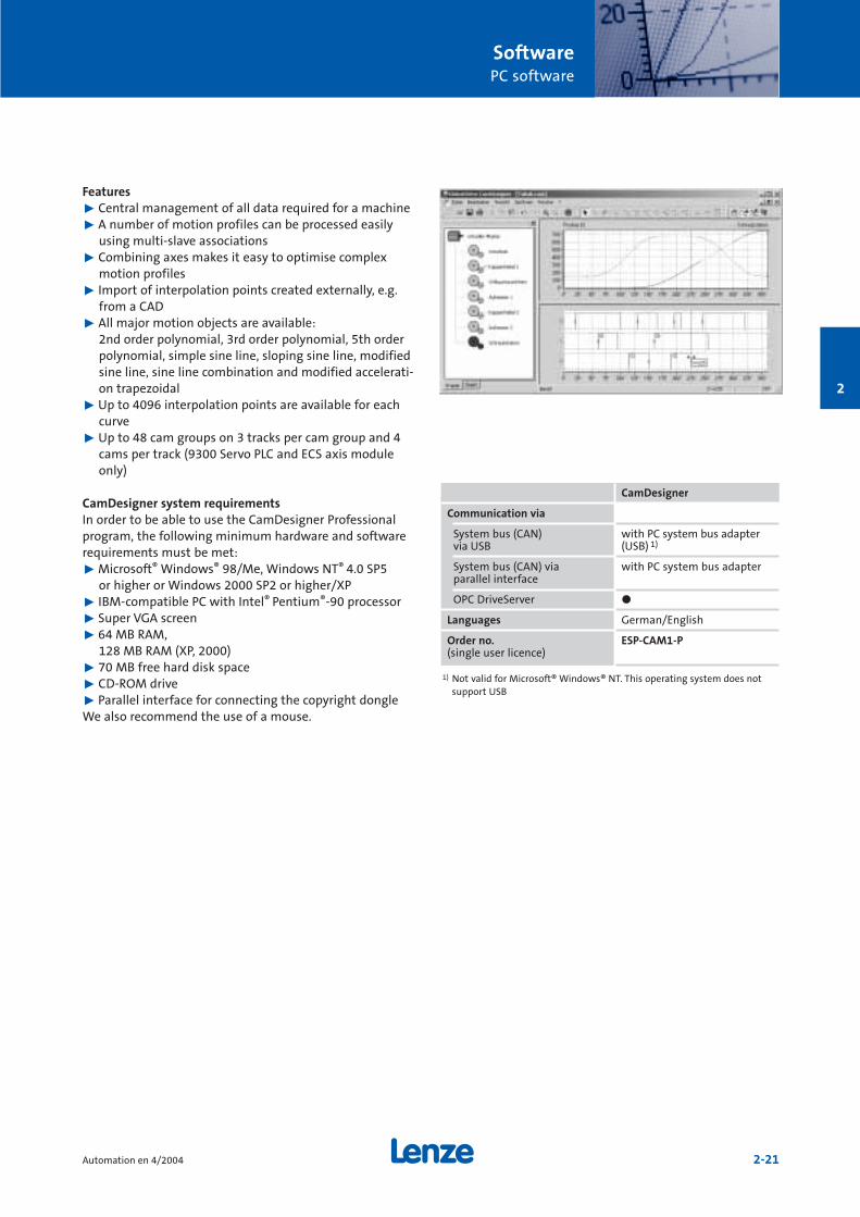
2
Features˘ Central management of all data required for a machine˘ A number of motion profiles can be processed easily
using multi-slave associations˘ Combining axes makes it easy to optimise complex
motion profiles˘ Import of interpolation points created externally, e.g.
from a CAD˘ All major motion objects are available:
2nd order polynomial, 3rd order polynomial, 5th orderpolynomial, simple sine line, sloping sine line, modifiedsine line, sine line combination and modified accelerati-on trapezoidal
˘ Up to 4096 interpolation points are available for eachcurve
˘ Up to 48 cam groups on 3 tracks per cam group and 4cams per track (9300 Servo PLC and ECS axis moduleonly)
CamDesigner system requirementsIn order to be able to use the CamDesigner Professionalprogram, the following minimum hardware and softwarerequirements must be met:˘ Microsoft® Windows® 98/Me, Windows NT® 4.0 SP5
or higher or Windows 2000 SP2 or higher/XP˘ IBM-compatible PC with Intel® Pentium®-90 processor˘ Super VGA screen˘ 64 MB RAM,
128 MB RAM (XP, 2000)˘ 70 MB free hard disk space˘ CD-ROM drive˘ Parallel interface for connecting the copyright dongleWe also recommend the use of a mouse.
CamDesigner
Communication via
System bus (CAN) with PC system bus adapter via USB (USB) 1)
System bus (CAN) via with PC system bus adapterparallel interface
OPC DriveServer ö
Languages German/English
Order no. ESP-CAM1-P(single user licence)
1) Not valid for Microsoft® Windows® NT. This operating system does notsupport USB

SoftwarePC software
2-22 Automation en 4/2004
2
HMI DesignerVersion 1.6
The transparent programming environment and optimumadaptation to Lenze controller makes creating a project onthe operator terminal as easy as using it later..
This tool can be used to export and import any text forsimple translation into other languages. Once created,variables and recipes can be transferred to other devices inthe HMI range.
HMI Designer system requirementsHardware:˘ Microsoft® Windows® 95/98/NT 4.0 SP5 or
higher/2000/XP˘ IBM-compatible PC (Pentium® 166 processor or higher)˘ 32 MB RAM˘ 100 MB free hard disk space˘ CD-ROM drive˘ Free serial interface We also recommend the use of a mouse.
HMI Designer
Communication via
serial interface ö
(download cable suppliedwith the software)
Languages German/English
Order no. ESP-HMI1-P(corporate licence)
œNew version

Version 2.1
The Global Drive Loader (GD Loader) makes standard setupsignificantly easier. It is very easy to use, as there is noneed for a development environment or parameter set-tings. Compiled PLC programs (files from the Drive PLCDeveloper Studio) and parameter set files (files from GlobalDrive Control) can simply be transferred from the PC to thetarget system. As these files cannot be modified with GDLoader, this prevents data being tampered with by unaut-horised users.
The advantages for you˘ Dedicated program for setting up inverters in standard
machines˘ Data cannot be tampered with˘ Simplest possible operation without development
environment˘ Automatic batch mode provides a quick and easy way of
transferring a variety of files to a number of targetsystems
˘ Software is free of charge
You can continue to use the following software products tomodify and create files:˘ Drive PLC Developer Studio V1.0 or higher˘ Global Drive Control V4.31 or higher
The latest version of GD Loader can be downloaded free ofcharge from the Downloads area at www.Lenze.com. AGD Loader is also supplied on the CDs for the followingsoftware products. Depending on the version, CDs may notcontain the latest version of GD Loader.˘ Drive PLC Developer Studio V2.0 or higher˘ Global Drive Control V4.5 and higher˘ Global Drive Control easy V4.5 or higher
Target systemsGD Loader V2.1 can be used for the following targetsystems:˘ 8200 vector/8200 motec˘ 9300 Servo PLC˘ Drive PLC˘ Terminal extension˘ ECS servo system
Global Drive Loader system requirementsIn order to be able to use the Global Drive Loader, the follo-wing minimum hardware and software requirements mustbe met:˘ Microsoft® Windows® 98/Me, Windows NT® 4.0 SP5 or
higher or Windows 2000 SP2 or higher/XP˘ IBM-compatible PC with Intel® Pentium®-90 processor˘ 32 MB RAM˘ 15 MB free hard disk space˘ CD-ROM drive for CD version˘ Free slots/interfaces in accordance with the require-
ments of the fieldbus interface module to be used˘ Mouse
SoftwarePC software
2-23Automation en 4/2004
2
1) Not valid for Microsoft® Windows® NT. This operating system does notsupport USB
GD Loader V2.1
Communication via
System bus (CAN) with PC system bus adapter via USB (USB) 1)
System bus (CAN) via with PC system bus adapter parallel interface
Languages German/English/French
Order no. Corporate licence can be downloadedfree of charge from www.Lenze.com
Global Drive Loader œNew version

2
SoftwareTechnology packages
2-24 Automation en 4/2004
Software Package – PositionerVersion 3.1
In modern production processes, positioning tasks areincreasingly being solved with intelligent servo drives.Motion sequences are stored in the controller.
The advantages˘ Increased flexibility due to programming freedom˘ Reduced energy consumption due to optimum motion
sequences˘ Reduced wear due to jerk-free acceleration
Applications/Application examples˘ Transporting materials˘ Stacking and storage˘ Surface machining˘ Rotary tables˘ Robots˘ Machine tools
Features˘ Freely selectable number of travel profiles (max. 128)˘ Travel profiles can be activated in any order˘ Sequence control via IEC 61131-3˘ Positioning with:
– Jerk limitation– Speed/acceleration override– Final speed (velocity changeover)– Distance-to-go (touch probe)
˘ 16 reference modes including set reference˘ Manual control or handwheel e.g. for reading in
positions (teach-in)˘ Software stop monitoring
NotePlease note that the Positioner software package is an add-on for the Drive PLC Developer Studios and requires thetechnology variant of the 9300 Servo PLC (EVS93òòETòòò)
Order no.
Software Package – Positioner ESP-SPAC-POS1(corporate licence)
Palletizer Surface grinding machine

SoftwareTechnology packages
2-25Automation en 4/2004
2
Software package – CamVersion 1.2
In mechanical engineering, mechanical solutions for dyna-mic motion control are increasingly being replaced by intel-ligent servo drives with electronic cam functions.
The advantages˘ High dynamics due to optimum drive management˘ Low-jerk acceleration reduces wear˘ Significant reduction in setup and operating time and
costs
Lenze CamDesignerThe Lenze CamDesigner is an additional engineering toolfor the graphic creation of motion profiles. It can be used todisplay and edit all motion profiles in accordance with themotion plan for all drives on the machine, thereby ensuringhigh levels of transparency.
See page 2-20 for more detailed information aboutCamDesigner.
Applications/Application examples˘ Contouring˘ Filling˘ Packaging˘ Paper handling˘ Cross cutters
Features˘ Up to 48 cams with a maximum of 4096 interpolation
points˘ Pilot control of speed and torque for high dynamics˘ Cam group with 3 tracks each with 4 cams, maximum 48
data records˘ Motion profiles can be activated in any order, sequence
control via scheduler˘ The current profile can be stretched, compressed and
even moved online˘ 14 reference modes including set reference˘ Virtual master with:
– Inching mode/manual operation– Handwheel– Switching mode– Automatic mode
˘ Virtual clutch with position override function
Note˘ Please note that the Cam software package is an add-on
for the Drive PLC Developer Studios and requires thetechnology variant of the 9300 Servo PLC(EVS93òòETòòò)
˘ The Cam software package is supplied with a basic versi-on of the CamDesigner for the simple graphics-basedcreation of motion profiles.
Order no.
Software package – Cam ESP-SPAC-CAM1
CamDesigner Professional ESP-CAM1-P(corporate licence)
Nappy packaging machine
œNew version

SoftwareTechnology packages
2-26 Automation en 4/2004
Winder drives are used in numerous production processesto take up the material produced or forward it for proces-sing further along the production line. Where the open andclosed-loop technology required for such applications waspreviously implemented primarily in the higher-level PLC,intelligent controllers are now able to take over these func-tions.
The advantages ˘ Relieves the load on higher-level PLCs and bus systems˘ Setup is quick and easy thanks to standard solutions ˘ Drive-based functions are integrated directly in the drive
Areas of applicationThe "Winder" software package provides solutions for centrewinding machines with open-loop or closed-loop tensioncontrol or dancer control.
Features – Open-loop/Closed-loop tension control˘ Internal diameter calculation˘ Tensile force configured via ramp generator˘ Tensile force controlled via characteristic curve function˘ Automatic identification of the current moment of
inertia and prevailing friction˘ Acceleration torque and friction compensation˘ Calculation of material density with stop controller
Features - Dancer position control˘ Diameter calculated internally with dancing roller
motion compensation˘ Teaching of dancing roller stops˘ Tensile force controlled via characteristic curve function
using dancing roller˘ Automatic identification of the current moment of
inertia˘ Compensation of acceleration torque˘ Calculation of material density with stop controller
NotePlease note that the Winder software package is an add-onfor the Drive PLC Developer Studios and requires the tech-nology variant of the 9300 Servo PLC (EVS93òòETòòò)
2
Software Package – WinderVersion 2.0
Areas of application Open-loop and closed-loop concept
Cable, wire, textiles, paper Dancer position control
Sheet steel, textiles, film, paper Tension control
Thin film, paper Tension control
Order no.
Software Package – Winder ESP-SPAC-WND1(corporate licence)
Cable winder Paper winder

2-27Automation en 4/2004
2

3

3-1Automation en 4/2004
Industrial communication Automation
Components forindustrial communication
3-2
Overview of bus systems
3-4
Communication modules
CANopen/Lenze system bus 3-6DeviceNet 3-8PROFIBUS-DP 3-10INTERBUS 3-12INTERBUS Loop 3-14LON 3-15AS-i 3-16FP-Interface 3-17LECOM-A (RS232)/LECOM-B (RS485) 3-18LECOM-LI 3-20
System bus components
PC system bus adapter 3-22CAN repeater 3-23CAN addressing module 3-23
3

Components for industrial communication
Industrial communication is being used in an increasingnumber of industry sectors and therefore in an increasingnumber of applications. Lenze can provide easy-to-installfieldbus modules for the various bus systems.
Lenze supports communication via the following bussystems:˘ INTERBUS (slave)˘ DeviceNet (slave)˘ INTERBUS Loop (slave)˘ LECOM-A/B/LI (slave)˘ PROFIBUS-DP (slave)˘ CAN˘ AS-i (slave)˘ CANopen (slave)˘ LON
Pages 3-4 and 3-5 contain detailed information about thebus systems and list suitable fieldbus modules for eachcontroller.
Communication and function modulesLenze makes a distinction between communication modu-les and function modules. One of the things shown by thetable below is that both types of module can be used onthe 8200 vector frequency inverter.
Communication modules (AIF = Application Interface)are used in any application in which communication with acontroller must take place via the fieldbus and digital andanalog signals need to be read in in parallel via I/O functionmodules.
Configuration examples
8200 vector frequency inverter with˘ INTERBUS communication module˘ Standard I/O function module
The communication module connects thefrequency inverter with a master control. Digital and analog signals can be read in
Fieldbus function modules (FIF = Function Interface) can beused for communication with other communicationpartners via the fieldbus and a keypad for parameter set-ting and diagnostics can be plugged into the higher-levelinterface.
The table below shows the types of module supported byeach controller.
These modules can be used on the various controllers, mea-ning that once you have learnt how to use these moduleson one Lenze controller, you will be able to use them onothers, saving an enormous amount of money as there isno need for separate training sessions.
Conclusion:This modular concept enables the controller to meet ever-changing requirements.
8200 vector frequency inverter with˘ Keypad XT˘ PROFIBUS function module
Whilst the controller is being diagnosed viathe keypad, the fieldbus function module iscommunicating with the master control.
Industrial communicationComponents for industrial communication
3-2 Automation en 4/2004
3
Communication Fieldbusmodules function modules
(AIF) (FIF)
9300 Servo ö
9300 Servo PLC ö
Drive PLC ö CAN only (E82ZAFCC,E82ZAFCC001, E82ZAFCC010)
9300 vector ö
8200 vector ö ö
8200 motec ö
starttec ö
PLC with PROFIBUSmaster

Industrial communicationComponents for industrial communication
3-3Automation en 4/2004
3
Communication modules (AIF) Fieldbus function modules (FIF)˘ PROFIBUS-DP˘ INTERBUS ˘ Lenze system bus (CAN)˘ CANopen (in preparation)˘ DeviceNet (in preparation)˘ AS-i˘ LECOM-B (RS485)
Lenze can provide the following modules for the controller:
<
<
˘ PROFIBUS-DP˘ INTERBUS ˘ INTERBUS Loop˘ Lenze system
bus˘ CANopen /
DeviceNet
˘ LON˘ LECOM-A/B
(RS232/RS485) ˘ LECOM-B
(RS485) ˘ LECOM-LI ˘ LECOM-A
(RS232)

Industrial communicationOverview of bus systems
3-4 Automation en 4/2004
3
Features of the bus systems
Topology Bus administration Max. Max. Max. Possible Auxiliary power Transfer
no. of distance betw. distance betw. transfer supply rate
nodes nodes nodes medium via bus
(master and without with cable
slaves) repeater repeater
CAN/CANopen Line with Multi-master 64 Depends on the General Shielded Possible via 10 kBaud
terminating baud rate reduction in twisted separately to 1 MBaud
resistors used and length; 2-wire cable via additional
module depends on the cables in
used; repeater the bus cable
approx. 1 km at used
50 kBaud;
approx. 25 m at
1 MBaud
DeviceNet Line with Single-master 64 100 m Not specified Shielded Separate via 125, 250,
terminating (500 kBaud); twisted additional 500 kBaud
resistors 250 m 2-wire cable cables
(250 kBaud); in the bus cable
500 m (125 kBaud)
PROFIBUS-DP Line with Single-master 124 (4 segm., 1.2 km 10 km Shielded Separate via 9.6 kBaud to
terminating 3 repeaters), (93.75 kBaud); (93.75 kBaud) twisted additional to 12 MBaud
resistors max. 32 per 100 m (12 MBaud) 2-wire cable cables
segm. in the bus cable
AS-i Line, tree Single-master 124 sensors/ 100 m 300 m Unshielded Power supply 167 kBaud
(ring possible) actuators, (2 repeaters) untwisted via data line
1 master 2-wire (2 to 8 A)
flat cable
INTERBUS Ring Single-master 512 slaves, 1.5 m (local bus); 13 km (remote bus); Shielded Separate, group 500 kBaud
1 master 400 m (remote bus); 100 km optical fibre twisted via bus terminal or 2 MBaud
2.5 km optical fibre 5-wire cable (remote bus)
optical fibre, infrared
INTERBUS Loop Ring Only in 32 slaves 10 m (max. 100 m No repeaters Unshielded Power supply 500 kBaud
conjunction cable length required twisted via data line
with INTERBUS-S; without repeaters) 2-wire cable (approx. 1.5 A)
single-master
(bus terminal)
LON Line (2-wire) Multi-master 32385 stations 2 km at 78 kBaud Almost any; Unshielded Possible separately 78 kBaud
or any distributed on (twisted pair); can be expanded untwisted via additional to 1.25 MBaud
255 sub-networks 6.1 km at using sub-networks 2-wire cable cables
each with 127 5.48 kBaud no repeaters) (radio); optical fibre, in the
nodes (optical fibre plastic) network (Powerline) bus cable

Industrial communicationOverview of bus systems
3-5Automation en 4/2004
3
Lenze communication modules
Typical Message Message Bus access 9300 Servo 8200 vector 8200 motec starttec Drive PLC
update time (e.g. length length method inverter/ frequency
8 nodes (user data) (total) 9300 Servo PLC inverter
4 bytes of user
data
Approx. 1.32 ms at 0 to 8 bytes 106 bits for 8 bytes of CSMA/CA On-board (only parts Supports Supports Supports Supports
1 MBaud user data message- of CANopen); function module function module function module function module
(high priority) based CANopen system bus system bus system bus system bus
EMF2175IB (only parts of E82ZAFCC001, E82ZAFCC001, E82ZAFCC010
(pluggable) CANopen): (only parts of (only parts of (only parts of
E82ZAFCC010 CANopen), CANopen), CANopen),
or E82ZAFUC001* E82ZAFUC001* or pluggable
E82ZAFCC100, (CANopen) (CANopen) EMF2175IB
E82ZAFCC210,
E82ZAFUC010*,
or pluggable
EMF2175IB
(CANopen),
EMF2171IB,
EMF2172IB (parts
of CANopen)
Approx. 2.64 ms at 0 to 8 bytes 106 bits with 8 bytes CSMA/CA EMF2175IB Supports Supports Supports EMF2175IB
500 kBaud of user data message- (pluggable) function module function module function module (pluggable)
(high priority) based E82ZAFVC010*, E82ZAFVC001* E82ZAFVC001*
pluggable
EMF2175IB
Approx. 2.5 ms at 0 to 246 bytes User data + Cyclic polling EMF2133IB Supports Supports Supports EMF2133IB
500 kBaud 6 to 11 bytes (pluggable) function module function module function module (pluggable)
E82ZAFPC010 or E82ZAFPC001 E82ZAFPC001
EMF2133IB
Typ. 5 ms 4 bits 21 bits Cyclic polling Not available Supports Supports Built into Not available
(4 bits each) (14 master bits, function module function module device
7 slave bits) E82ZAFFC010 E82ZAFFC001 as variant
Min. 2 ms 1 to 64 bytes User data + Frame/ EMF2113IB Supports Supports Supports EMF2113IB
(process data) of data, up to 246 bytes 6 bytes distributed (pluggable) function module function module function module (pluggable)
of parameters shift register E82ZAFIC010, E82ZAFIC001 E82ZAFIC001
or pluggable
EMF2111IB or
EMF2113IB
Min. 2 ms 1 to 64 bytes User data + Frame/ EMF2112IB EMF2112IB Not Not EMF2112IB
(process data) of data, up to 246 bytes 6 bytes distributed (pluggable) (pluggable) available available (pluggable)
or parameters shift register
Approx. 70 ms 1 to 228 bytes, Max. 255 bytes, Modified EMF2141IB EMF2141IB Not Not EMF2141IB
typically appr. User data + CSMA/CD (pluggable) (pluggable) available available (pluggable)
11 bytes 27 Byte
* In preparation

Industrial communicationCommunication modules
3-6 Automation en 4/2004
3
CANopen/Lenze system bus
The system bus (CAN) is used for communication betweenLenze devices and provides a quick and easy means notonly of connecting a number of inverters but also of esta-blishing connections to other external add-on componentssuch as operator/display terminals.
The following are examples of functions the system buscan add to the controller:˘ Parameter setting˘ Data transfer between inverters˘ Connection to external controllers and host systems˘ Option to connect to:
– Decentralised I/O systems– Operator/display terminals
EMF2171IB:Supports part of the CANopen com-munication profile.
EMF2172IB:Additional function not offered bythe EMF2171IB: DIP switch for setting the node address and baudrate.
EMF2175IB:The EMF2175IB module supports theCANopen communication profile toDS301 V4.01. The node address andbaud rate are set via a DIP switch. (TheDIP switch can also be used to changethe communication profile over toDeviceNet.)
E82ZAFCC:System bus function module; com-munication module used based onCANopen (also available in coatedversion, variant V001).
E82ZAFCC010:System bus function module, asE82ZAFCC but with the addition of apluggable terminal strip.
E82ZAFCC100:System bus function module with 2 freely programmable digital inputterminals, pluggable terminal strip,external supply for module and con-trol card on the controller for para-meter setting, even if the controlleris isolated from the mains.
E82ZAFCC200:System bus function module with2 freely programmable digital inputterminals (also available in coatedversion, variant V001).
E82ZAFCC210:System bus function module with 2 freely programmable digital inputterminals and pluggable terminalstrip.
E82ZAFUC001:CANopen function module supportsCANopen DS301 V4.02, coated versi-on.Electrically isolated from the busand voltage supply. In preparation.
E82ZAFUC010:CANopen function module supportsCANopen DS301 V4.02, with plugga-ble terminal strip. Electrically isola-ted from the bus and voltage supply.In preparation.

Industrial communicationCommunication modules
3-7Automation en 4/2004
3
General data and operating conditions
Communication profile ˘ CANopen compatible to DS301 V4.01: EMF2175IB˘ CANopen compatible to DS301 V4.02: E82ZAFUC001 2), 3)
E82ZAFUC010 3)
˘ Based on CANopen – parts of CANopen were used:EMF2171IB, EMF2172IB, E82ZAFCC, E82ZAFCC010, E82ZAFCC100,E82ZAFCC200, E82ZAFCC210
Communication medium DIN ISO 11898
Network topology Line (terminated at both ends with 120 Ω)
Number of logic process data channels AIF: 2171 / 2172:1; 2175:3 FIF: 2, except E82ZAFUòòò:4
Number of logic parameter data channels 2 (1 or 2 can be selected on the E82ZAFUCòòò)
Nodes Slave (CANopen), multi-master (Lenze system bus)
Max. number of nodes 63 (on the E82ZAFUCòòò: 106 physically)
Max. distance between two nodes Unlimited, determined by max. bus length
Baud rate [kBps] 10 20 50 125 250 500 1000
2171 / 2172: Max. bus length [m] 1) – – 1550 630 290 120 25
2175: Max. bus length [m] 1) 7450 3950 1550 630 290 120 25
E82ZAFCCòòò: Max. bus length [m] 1) – 3910 1510 590 250 80 –
E82ZAFCC100 : Max. bus length [m] 1) – 3930 1530 610 270 100 9
E82ZAFUCòòò: Max. bus length [m] 1) 3) 7434 3984 1534 614 274 104 9
DC voltage supply Internal and external possible(if the controller fails, the bus system will continue to operate)
Ambient temperature FIF: AIF:Transport: -25 ... +70°C -25 ... +70°CStorage: -25 ... +60°C -25 ... +60°COperation: -20 ... +60°C -20 ... +55°C
Climatic conditions Class 3K3 to EN 50178(without moisture condensation, average relative humidity 85%)
Can be used on EVò93òò-òò: EMF2175IBE82EVòòò: EMF2171IB, EMF2172IB, EMF2175IB, E82ZAFCCòòò
E82ZAFUCòòò 3)
E82MVòòò: E82ZAFCC001 2), E82ZAFCC201 2), E82ZAFUC001 3)
Drive PLC: EMF2175IB, E82ZAFCC010starttec: E82ZAFCC001, E82ZAFUC001 3)
ECS axis module: EMF2175IB
Order no. for AIF EMF2171IB, EMF2172IB, EMF2175IB
Order no. for FIF E82ZAFCC, E82ZAFCC001 2), E82ZAFCC010, E82ZAFCC100,E82ZAFCC200, E82ZAFCC201 2), E82ZAFCC210, E82ZAFUC001 2) 3), E82ZAFUC010 3)
1) You should be aware of the additional effect of the number of devices andthe cable cross-section used on the maximum bus cable lengths.
2) E82ZAFCCòò1 = Coated version3) In preparation

Industrial communicationCommunication modules
3-8 Automation en 4/2004
3
DeviceNet
The DeviceNet fieldbus has been particularly successful inthe American and Asian markets. The DeviceNet modulecan function in two operating modes - DeviceNet andCANopen.
The DIP switch on the front panel of the function module can be used to make the following settings:˘ Node address˘ Baud rateThe DIP switch can be used to change over from theDeviceNet communication profile to CANopen and viceversa.
EMF2175IB:DeviceNet communication modulewith pluggable terminal strip.
E82ZAFVC001:DeviceNet function module, coatedversion, electrically isolated from thebus.
E82ZAFVC010:DeviceNet function module with pluggableterminal strip and electrical isolation fromthe bus.

Communication medium DIN ISO 11898
Communication profile DeviceNet
Baud rate [kBps] 125 250 500
Max. bus length [m]
EMF2175IB, E82ZAFVC010 1) 500 250 100
E82ZAFVC001 1) 100 100 100
DeviceNet node Slave
Network topology Line with terminating resistors (120 Ω)
Process data words (PZD) (16 bits) 12
Number of nodes Max. 63
DC voltage supply ˘ Internal˘ External
– Only necessary if bus stations which have been disconnected fromthe mains need to maintain communication with the master
– Supplied via terminal connectors with a separate DC voltage supply, +24 V ± 10%; max. 100 mA
Ambient temperature Transport: -25 ... +70°CStorage: -25 ... +60°COperation: -20 ... +55°C
Climatic conditions Class 3K3 to EN 50178(no moisture condensation, average relative humidity 85%)
Can be used on EVò93òò-òò: EMF2175IBE82EVòòò: EMF2175IB, E82ZAFVCòòò 1)
E82MVòòò: E82ZAFVC001 1)
Drive PLC: EMF2175IBstarttec: E82ZAFVC001 1)
ECS axis module: EMF2175IB
Order no. for AIF EMF2175IB
Order no. for FIF E82ZAFVCòòò 1)
Industrial communicationCommunication modules
3-9Automation en 4/2004
3
General data and operating conditions
1) In preparation

Industrial communicationCommunication modules
3-10 Automation en 4/2004
3
PROFIBUS-DP
The PROFIBUS module is a slave connection module withthe PROFIBUS-DP communication profile. It is used for networking between the controller and inverter at highprocessing speeds. It provides a user-friendly way of integrating the inverter into the overall system network.
All modules are electrically isolated from the bus.
EMF2133IB:The address is set via a DIP switch.In addition, the function - and the-refore the code - of the EMF2131IB(predecessor of the 2133IB module)can also be activated.
E82ZAFPC:The bus terminating resistor can beactivated via a DIP switch. Alsoavailable in a coated version for usein industrial environments (variantV001).
E82ZAFPC010:Functions as the E82ZAFPC but isalso fitted with a pluggable termi-nal strip.

Communication medium RS485
Communication profile PROFIBUS-DP (DIN 19245 Part 1 and Part 3)
Selectable drive profile ˘ DRIVECOM profile "Drive technology 20"˘ PROFIDRIVE (EMF2133IB only)˘ Lenze device control
Baud rate [kBps] 9.6 ... 12000 (automatic detection)
PROFIBUS-DP node Slave
Network topology No repeaters: LineWith repeaters: Line or tree
Process data words (PZD) (16 bits) FIF: 1 ... 10/AIF: 2133: 1 ... 12
DP user data length Parameter channel (4 words) + process data words
Number of nodes Standard: 32 (= 1 bus segment)With repeaters: 125 (slaves)
Max. cable length per bus segment 1200 m (depending on the baud rate and the type of cable used)
DC voltage supply ˘ Internal˘ External
– only necessary if nodes which have been disconnected from the mains need to maintain communication with the master
– Bus devices with activated bus terminating resistor are disconnectedfrom the mains but the bus system is to remain active
– Power is being provided via a separate power supply– +24 V DC ± 10%, max. 120 mA
Ambient temperature FIF: AIF:Transport: -25 ... +70°C -25 ... +70°CStorage: -25 ... +60°C -25 ... +60°COperation: -20 ... +60°C -20 ... +55°C
Climatic conditions Class 3K3 to EN 50178(no moisture condensation, average relative humidity 85%)
Can be used on EVò93òò-òò: EMF2133IBE82EVòòò: EMF2133IB, E82ZAFPCòòò
E82MVòòò: E82ZAFPC001 1)
Drive PLC: EMF2133IBstarttec: E82ZAFPC001 1)
ECS axis module: EMF2133IB
Order no. for AIF EMF2133IB
Order no. for FIF E82ZAFPC, E82ZAFPC001 1), E82ZAFPC010
Industrial communicationCommunication modules
3-11Automation en 4/2004
3
General data and operating conditions
1) Coated version

Industrial communicationCommunication modules
3-12 Automation en 4/2004
3
INTERBUS
INTERBUS is connected directly to the remote bus. The DRI-VECOM profile 20 or 21 is supported for this connection. Anexternal DC voltage (24 V) can be connected to the modu-les. This means that the fieldbus will continue to operateeven if the controller is disconnected from the mains.
EMF2111IB:INTERBUS connection to the remotebus.
EMF2113IB:DIP switches for setting process dataand PCP data are located on themodule. In addition to the functionsof the EMF2111IB, the EMF2113IBmodule offers other options such astransferring a maximum of 10 pro-cess data words. The module is elec-trically isolated from the incomingbus.
E82ZAFIC:INTERBUS function module forconnection to the remote bus (alsoavailable in a coated version in vari-ant V001). The module is electricallyisolated from the incoming and out-going bus.
E82ZAFIC010:Functions as the E82ZAFIC but is alsofitted with a pluggable terminalstrip. The module is electrically isola-ted from the incoming and outgoingbus.

Communication medium RS485
Selectable drive profile ˘ Lenze device control˘ DRIVECOM profile "Drive technology 21" (supports EMF2111IB,
EMF2113IB)˘ DRIVECOM profile "Drive technology 20" (supports E82ZAFIC)
Baud rate [kBps] 500 kBaud (EMF2113IB also supports 2 MBaud)
INTERBUS node Slave
Network topology Ring (go and return lines in the same bus cable)
Process data words (PZD) (16 bits) FIF: 1 ... 6 AIF: EMF2111IB: 2 ... 3; EMF2113IB: max. 10
Parameter data words (PCP) (16 bits) FIF: 0 / 1 AIF: 1 (2 or 4 words = EMF2113IB)
Maximum PDU length 64 bytes
PCP services supported Initiate, Abort, Status, Identify, Get-OV-Long, Read, Write
Number of nodes Depends on host system (I/O area), max. 63
Max. distance between 2 nodes 400 m
DC voltage supply ˘ Internal˘ External
– only necessary if the communication ring must not be interruptedif a node is switched off or fails
– Power is being provided via a separate power supply– +24 V DC ± 10%, max. 150 mA
E82ZAFICòòò: Terminal 59 (supply voltage) can be loaded with amaximum of 3 A when the supply voltage is looped through toother nodes
Ambient temperature FIF: AIF:Transport: -25 ... +70°C -25 ... +70°CStorage: -25 ... +60°C -25 ... +60°COperation: -20 ... +60°C 0 ... +55°C
Climatic conditions Class 3K3 to EN 50178(no moisture condensation, average relative humidity 85%)
Can be used on EVx93òò-òò: EMF2113IBE82EVòòò: EMF2111IB, EMF2113IB, E82ZAFICòòò
E82MVòòò: E82ZAFIC001Drive PLC: EMF2113IBstarttec: E82ZAFIC001ECS axis module: EMF2113IB
Order no. for AIF EMF2111IB, EMF2113IB
Order no. for FIF E82ZAFIC, E82ZAFIC001, E82ZAFIC010
Industrial communicationCommunication modules
3-13Automation en 4/2004
3
General data and operating conditions

Industrial communicationCommunication modules
3-14 Automation en 4/2004
3
INTERBUS Loop
The INTERBUS Loop is used in conjunction with INTERBUS.The protocol used is identical to INTERBUS, although poweris supplied directly via the bus.
Communication medium RS485
Selectable drive profile Lenze device controlDRIVECOM profile "Drive technology 20"
Baud rate [kBps] 500
Network topology Ring
Process data words (PZD) (16 bits) 2 words
Parameter data words (PCP) (16 bits) Not supported
INTERBUS code (ID code) Decimal: 179; hex: B3
Maximum PDU length 4 bytes
PCP services supported None
Number of nodes Depends on the current consumption (max. 36 Lenze drives)
Max. distance between 2 nodes 20 m
DC voltage supply Via the bus
Ambient temperature Transport: -25 ... +70°CStorage: -25 ... +60°COperation: -20 ... +55°C
Climatic conditions Class 3K3 to EN 50178(no moisture condensation, average relative humidity 85%)
Can be used on EVx93òò-òò, E82EVòòò, Drive PLC, ECS axis module
Order no. for AIF EMF2112IB
General data and operating conditions
EMF2112IB

Communication medium FTT (Free Topology Transceiver) - 10 A
Communication profile LONMARK® "Variable Speed Motor Drive" functional profile
Network topology Free topology (line, tree/line, star, ring)
Possible number of nodes 64
Max. cable length 2700 m for bus topology (line)500 m for mixed topology
Baud rate [kBps] 78
Electrical connection Pluggable screw terminal
DC voltage supply ˘ Internal˘ External
– Only necessary if a node is switched off or fails but communicationwith this node needs to be maintained
– Power is being provided via a separate power supply– +24 V DC ± 10%, max. 120 mA per module
Ambient temperature Transport: -25 ... +70°CStorage: -25 ... +60°COperation: 0 ... +55°C
Climatic conditions Class 3K3 to EN 50178(no moisture condensation, average relative humidity 85%)
Can be used on EVS93òò-òò, E82EVòòò, Drive PLC, ECS axis module
Order no. EMF2141IB
Industrial communicationCommunication modules
3-15Automation en 4/2004
3
LON
The communication module enables the inverter to supportthe LONMARK "Variable Speed Motor Drive" functionaldevice profile.˘ In order that the new LON station can be integrated
quickly, a service button is located on the LON module.Press this button to register the new LON station on thenetwork so that it will be detected by all other stations.
Note:˘ A configuration diskette for LON containing the descrip-
tion file for the devices and the pluggable for theLonMaker software is included in the scope of supply.
General data and operating conditions
EMF2141IB

Industrial communicationCommunication modules
3-16 Automation en 4/2004
3
AS-i
The AS-i bus system has established itself for use at thelowest field level, particularly for digital signal transfer.
It is designed for applications that do not necessarilyrequire powerful fieldbus systems, but nonetheless need toexploit the advantages of serial communication.
The advantages of this system are:˘ Easy to use and to set up˘ Less wiring required˘ AS-i station power supply provided via data line˘ Easy to integrate into existing systems˘ Reduces costs
Note:Two LEDs are located on the function module to indicatethe communication status.
The following are available:˘ 4 data bits to the controller (actuation)
The bits can be freely assigned in the controller.Example:– Bit 1 is assigned the function “Fixed setpoint 1”– Bit 2 is assigned the function “Fixed setpoint 2”“– Bit 3 is assigned the function "DC injection brake"– Bit 4 is assigned the function "Reversal of direction ofrotation"
˘ 1 data bit from the controller (feedback).This bit can be freely assigned in the controller, e.g. witha trip error message.
Protocol/communication medium AS-i specification V2.1 single slave
Network topology Tree
Node Slave
Max. number of nodes 31
Baud rate [kBps] 167
Cycle time [ms] 5 ms (31 nodes)
Max. bus length [m] 100
Electrical connection (AS-i terminal strip) Screw terminals, 1.5 mm2 (AWG 16)
Tightening torques 0.5 ... 0.6 Nm (4.4 ... 5.3 Ib-in)
Function moduleDC voltage supply via the bus
Ambient temperature Transport: -25 ... +70°CStorage: -25 ... +60°COperation: -20 ... +60°C
Climatic conditions Class 3K3 to EN 50178(no moisture condensation, average relative humidity 85%)
Can be used on E82EVòòò: E82ZAFFCòòò
E82MVòòò: E82ZAFFC001
Order no. E82ZAFFC, E82ZAFFC001, E82ZAFCC010
General data and operating conditions
E82ZAFFCE82ZAFFC010:With pluggable terminal strip.

Industrial communicationCommunication modules
3-17Automation en 4/2004
3
FP-Interface
The EMF2103IB pluggable module can be used to controlI/O devices on a freely programmable RS232 interface, i.e.any data can be sent and received in series via this interface.
This means for example that printers, modems, measu-ring devices and any other systems with a serial RS232interface can be controlled.
This communication module is compatible with the DrivePLC and the Servo PLC. This RS232 interface can be freelyprogrammed with an appropriate application program onthe basis of the PLC programming standard IEC61131-3. A corresponding function library is available.
EMF2103IB
Communication medium RS232
Communication protocol Freely programmable using the IEC61131-3 program on the Drive PLCand Servo PLC
Transfer character format Configurable: 7/8 data bits
Response to transmission errors Parity/frame/overrun error
Baud rate [kBps] 600, 1200, 2400, 4800, 9600, 19200, 38400
Max. number of nodes 1
Max. cable length 15 m
DC voltage supply Uses the basic device internal voltage supply
Ambient temperature Transport: -25 ... +70°CStorage: -25 ... +60°COperation: 0 ... +55°C
Climatic conditions Class 3K3 to EN 50178 (no moisture condensation, average relativehumidity 85%)
Can be used on 9300 PLC and Drive PLC
Order no. EMF2103IB
General data and operating conditions

Industrial communicationCommunication modules
3-18 Automation en 4/2004
3
LECOM-A (RS232)/LECOM-B (RS485)
The Lenze LECOM protocol is used for communication viaLECOM-A (RS232)/LECOM-B (RS485) bus modules. This pro-tocol is open to the user. It is supplied as an integral com-ponent of a number of systems (e.g. Simatic S5).
These modules are electrically isolated not only from thebus but also from the external voltage supply:
These modules are electrically isolated from the bus:
EMF2102IBCV001:Supports LECOM-A (RS232) andLECOM-B (RS485).
EMF2102IBCV002:Supports LECOM-B (RS485).
EMF2102IBCV004:Supports LECOM-A (RS232) and usesonly the basic device internal volta-ge supply.
E82ZAFLC:Supports LECOM-B (RS485)(also available in a coated versionfor use in industrial environments(variant V001)).
E82ZAFLC010:Functions as the E82ZAFLC modulebut with the addition of a pluggableterminal strip.

Communication medium RS232 (LECOM-A), RS485 (LECOM-B)
Communication protocol LECOM-A/B V2.0
Transfer character format 7E1: 7 bits ASCII, 1 stop bit, 1 start bit, 1 parity bit (even)
Baud rate [kBps] 1200, 2400, 4800, 9600, 19200(plus 38400, 57600 on the E82ZAFLCòòò)
LECOM node Slave
Network topology No repeaters: LineWith repeaters: Line or tree
Process data words (PZD) (16 bits) 2 words (FIF only), otherwise parameter data transfer only
Max. number of nodes 31 (= 1 bus segment) + 1 masterWith repeaters: 90
Max. cable length per bus segment 1200 m (depending on the baud rate and the type of cable used)
DC voltage supply ˘ Internal˘ External
– Necessary if nodes which have been disconnected from the mainsneed to maintain communication with the master
– Nodes with activated bus terminating resistor are disconnectedfrom the mains but the bus system is to remain active
– Power is being provided via a separate power supply– +24 V DC ± 10%, max. 80 mA
Ambient temperature FIF: AIF:Transport: -25 ... +70°C -25 ... +70°CStorage: -25 ... +60°C -25 ... +60°COperation: -20 ... +60°C -20 ... +55°C
Climatic conditions Class 3K3 to EN 50178(no moisture condensation, average relative humidity 85%)
Can be used on EVx93òò-òò: EMF2102IBCV00ò
E82EVòòò: EMF2102IBCV00ò, E82ZAFLCòòò
E82MVòòò: E82ZAFLC001Drive PLC: EMF2102IBCV00ò
ECS axis andsupply modules: EMF2102IBCV00ò
Order no. for AIF EMF2102IBCV001EMF2102IBCV002EMF2102IBCV004
Order no. for FIF E82ZAFLC, E82ZAFLC001, E82ZAFLC010
Industrial communicationCommunication modules
3-19Automation en 4/2004
3
LECOM-A accessoriesSystem cables of various lengths are available for connec-ting a LECOM-A module to the RS232 interface of a PC.
General data and operating conditions
Order no. for PC system cable (RS232, 5 m) EWL0020
Order no. for PC system cable (RS232, 10 m) EWL0021

Industrial communicationCommunication modules
3-20 Automation en 4/2004
3
LECOM-LI
The Lenze LECOM protocol is used for communication viathe LECOM-LI bus module. Data is transmitted via opticalfibres, which means that transmission is particularly stablewhen subject to external interference.
The LECOM protocol is open for the user. It is an integral component of a number of systems (e.g.Simatic S5).
The module is electrically isolated from the external vol-tage supply.
Communication medium Optical fibre
Communication protocol LECOM-A/B V2.0
Transfer character format 7E1: 7 bits ASCII, 1 stop bit, 1 start bit, 1 parity bit (even)
Baud rate [kBps] 1200, 2400, 4800, 9600, 19200
LECOM node Slave
Network topology Ring
Max. number of nodes 52
Max. cable length per bus segment 0 ... 40 m (standard output power)/10 ... 66 m (increased output power)
Electrical connection Screw-type crimp connection
DC voltage supply ˘ Internal˘ External
– only necessary if the communication ring must not be interruptedif a node is switched off or fails
– Nodes with activated bus terminating resistor are disconnectedfrom the mains but the bus system is to remain active
– Power is being provided via a separate power supply– +24 V DC ± 10%, max. 70 mA
Ambient temperature Transport: -25 ... +70°CStorage: -25 ... +60°COperation: 0 ... +55°C
Climatic conditions Class 3K3 to EN 50178(no moisture condensation, average relative humidity 85%)
Can be used on EVx93òò-òò: EMF2102IBCV003E82EVòòò: EMF2102IBCV003Drive PLC: EMF2102IBCV003ECS axis andsupply modules: EMF2102IBCV003
Order no. for AIF EMF2102IBCV003
General data and operating conditions
EMF2102IBCV003

Industrial communicationCommunication modules
3-21Automation en 4/2004
3
LECOM-LI accessoriesAs only a very small number of hosts have an optical fibreconnection, Lenze can supply an optical fibre adapter.
This optical fibre adapter should be connected directly tothe host's RS232 interface.
Communication medium To bus: optical fibre; to host computer: RS232
Max. cable length EMF2125IB 0 ... 40 m between 2 optical fibre stations
Max. cable length EMF2126IB 30 ... 66 m between 2 optical fibre stations
DC voltage supply Voltage supply via a power supply, order no. 362 016 forEMF2125IB and EMF2126IB; 9 V unstabilised or 9 ... 12 V stabilised; max. 70 mA
Optical fibre plug connection Crimp connection for optical fibre cable with 2.2 mm outer diameter
Ambient temperature Transport: 0 ... +45°CStorage: 0 ... +45°COperation: 0 ... +45°C
Climatic conditions 10 ... 90% rel. humidity; no condensation
Order no. EMF2125IB; EMF2126IB
Order no. for optical fibre cable with PE sleeve EWZ0007 (thermoplastic polyester)
Order no. for optical fibre cable with PUR sleeve EWZ0006 (thermoplastic polyurethane; designed for installationoutside the control cabinet)
General data and operating conditions
EMF2125IB optical fibreadapter

Industrial communicationSystem bus components
3-22 Automation en 4/2004
3
PC system bus adapter
The PC system bus adapter provides a quick and easymeans of connecting the PC for setting parameters on andprogramming the controller to the Lenze system bus (CAN).
For the printer portThis adapter simply plugs into the PC's parallel port. Therelevant drivers are installed automatically with the appropriate Lenze software. Depending on the version, thevoltage supply is provided via the DIN or PS2 connection onthe PC.
For the USB portThis adapter simply plugs into the PC's USB port. The rele-vant drivers are installed automatically with the appropria-te Lenze software. The voltage supply is USB port on whichever PC/laptop is used.
EMF2177IB
EMF2173IB V003
Order no. Brief description
EMF2177IB 1) USB system bus adapter; voltage supply also provided via the USB connection on the PC;electrically isolated from the CAN bus as standard
1) A CAN connecting cable (5 m)is included in the scope ofsupply
Order Brief description
EMF2173IB 1) System bus adapter; voltage supply viaDIN connection on PC
EMF2173IB V002 1) System bus adapter;voltage supply via PS2 connection on PC
EMF2173IB V003 1) System bus adapter; voltage supply via PS2 connection on PC; electrically isolated from the CAN bus

Communication medium DIN ISO 11898
Baud rate Up to 500 kbps
Signal runtime in repeater Approx. 150 ns from CAN1 to CAN2, thereby reducing the maximum bus length by approx. 30 m
Voltage supply 9 … 35 V DC, 150 mA typical
Ambient temperature Transport: -25 … +70°CStorage: -25 … +60°COperation: 0 … +55°C
Dimensions Approx. 110 x 75 x 22 mm
Other features ˘ CAN1 and CAN2 are electrically isolated from the voltage supply viaDC/D converters
˘ CAN1 is electrically isolated from CAN2˘ Terminating resistors are integrated in the repeater in CAN1 and in
CAN2
Order no. EMF2176IB
Industrial communicationSystem bus components
3-23Automation en 4/2004
3
CAN repeater
The CAN repeater can be used to electrically isolate twosegments on a CAN network and to access CAN communi-cation partners during operation (service interface).
This repeater can isolate a faulty CAN segmentfrom the rest of the network. The rest of the stations on thenetwork can continue to operate. Once the fault has beeneliminated, the segment concerned can be reconnected tothe CAN network.
Due to the physical features of the CAN bus, the use of aCAN repeater does not increase the maximum networkarea. However, the overall area of the network can beexpanded by selecting an appropriate topology.
Star and tree topologies can be set up using the repea-ter.
CAN addressing module
The CAN addressing module is used to set the controlleraddress and baud rate of the Lenze system bus for 8200vector and 9300 controllers (incl. all technology variants).
Additional features The controller address and baud rate are set by:˘ Encoding the 9-pin SUB-D plug
(appropriate connections must be established)˘ Setting the miniature switch in the addressing module
Order no. EMF2174IB
EMF2174IB
EMF2176IB

4

4-1Automation en 4/2004
Human machine interface Automation
Visualisation made easy
Text display 4-2Graphics display 4-2Touch screen 4-3HMI Designer 4-3
Technical data
H310 text display 4-4H315 text display 4-5H410 graphics display 4-6H502 touch screen 4-7H505 touch screen 4-8H510 touch screen 4-9H520 touch screen 4-10
Accessories
Protective foils 4-12Memory cards 4-12System cable for HMI Designer 4-13
4

4
Human machine interfaceVisualisation made easy
4-2 Automation en 4/2004
Visualisation made easy
Requirements of today's machines and systems in terms ofefficiency and effectiveness are constantly on the increase.User-friendliness and monitoring reliability for complexmachines are characteristics which are beginning to domi-nate. Lenze can provide a wide range of human machineinterface products, from text displays to graphics displaysand beyond to touch screen units, with just one softwareprogram common to all: the HMI Designer.
Select a multiplicity of functions according to device type,e.g.:˘ Display of text, images, bar graphs, bitmaps
and animated graphics˘ Recipe management˘ Display of system and alarm messages˘ Windows fonts˘ Automatic operations˘ Communication via Lenze system bus
Text displays
Text displays are a low-cost and compact solution for sim-ple applications. Their narrow mounting depth makes themideal if space is at a premium. The displays, which have bet-ween two and four lines, are backlit and feature a systembus as standard as well as various system and functionkeys.
Graphics displays
Graphics displays combine cost-effectiveness, functionalityand maximum user-friendliness in a modern design. The compact units with built-in system bus are able tomanage recipes and display data in graphic format.Production trends are immediately apparent, enablingmachine processes to be optimised.

Touch screens
Our range of touch screens can cater for all users, whetheryou are just starting out and are looking for a budget solu-tion or need an advanced solution for more complex visua-lisation applications, in which case our 10.4" TFT will beideal. All units are fitted with a system bus and boast anincredibly flexible user interface.
HMI Designer *
One software program for all units: The HMI Designer crea-tes an integrated development environment for all humanmachine interfaces described. The transparent program-ming environment with its Project Manager, Project Editorand Fonts Editor features optimum device configurationsfor Lenze controllers, making project planning and subse-quent operation easy.
* See Software section – PC software, page 2-22
Human machine interfaceVisualisation made easy
4-3Automation en 4/2004
4

4
Human machine interfaceTechnical data – H310 text display
4-4 Automation en 4/2004
Display H310
Type Text, backlit LED LC display
Display size [mm] 73.5 x 11.5
Lines x characters 2 x 20
Text character matrix (pixels) 5 x 7
Character size [mm] 3.2 x 5.5
User memory
Application program 48 kB
Interfaces
Serial port ASP8 RS232
Clock
Real-time clock with date –
Networks
Fieldbus CAN system bus
Dimensions
External (W x H x D) [mm] 166 x 86 x 45
Mounting cutout (W x H) [mm] 157 x 77
Technical data
Voltage supply 24 V DC (18 … 32 V DC)
Power consumption 24 V DC 5 W
Enclosure IP65 front panel
Operating temperature 0 … +50°C
Storage/transportation temperature -20 … +60°C
Humidity (no moisture condensation) <85%
Weight [kg] 0.5
Conformity CE, cULus
Product features
Online languages 4
Password –
Bit password 8 bits
Pages/Help 127/127
Variables per page 12
Variable format DEC, HEX, BIN, BCD, floating point
Dynamic texts ö
Alarms –
Info messages 128
Alarm buffer –
Recipes –
System and function keys 8/5
Type Order no.
H310 EPM-H310
Mounting cutout:

Human machine interfaceTechnical data – H315 text display
4-5Automation en 4/2004
4
Display H315
Type Text, backlit LED LC display
Display size [mm] 70.4 x 20.8
Lines x characters 4 x 20
Text character matrix (pixels) 5 x 7
Character size [mm] 2.95 x 4.75
User memory
Application program 256 kB
Interfaces
Serial port ASP8 RS232
Clock
Real-time clock with date –
Networks
Fieldbus CAN system bus
Dimensions
External (W x H x D) [mm] 148 x 188 x 45.5
Mounting cutout (W x H) [mm] 123 x 175
Technical data
Voltage supply 24 V DC (18 … 32 V DC)
Power consumption 24 V DC 15 W
Enclosure IP65 front panel
Operating temperature 0 … +50°C
Storage/transportation temperature -20 … +60°C
Humidity (no moisture condensation) <85%
Weight [kg] 0.7
Conformity CE, cULus
Product features
Online languages 6
Password 10 levels
Bit password 8 bits
Pages/Help 1024/1024
Variables per page 32
Variable format DEC, HEX, BIN, BCD, floating point
Dynamic texts ö
Alarms –
Info messages 1024
Alarm buffer –
Recipes –
System and function keys 20/5
Type Order no.
H315 EPM-H315
Mounting cutout:

4
Human machine interfaceTechnical data – H410 graphics display
4-6 Automation en 4/2004
Type Order no.
H410 EPM-H410
Display H410
Type Graphics, backlit LED LC display
Display size [mm] 132 x 39
Resolution 240 x 64
Lines x characters 2 x 10/4 x 20/8 x 40
Text character matrix (pixels) 6 x 8/12 x 16/24 x 32
Character size [mm] 3.2 x 4.2/6.5 x 8.5/12.7 x 17
User memory
Application program 512 kB
Interfaces
Serial port MSP RS232
Clock
Real-time clock with date Yes (with back-up battery)
Networks
Fieldbus CAN system bus
Dimensions
External (W x H x D) [mm] 252 x 196 x 65
Mounting cutout (W x H) [mm] 232 x 178
Technical data
Voltage supply 24 V DC (18 ... 32 V DC)
Power consumption 24 V DC 11 W
Enclosure IP65 front panel
Operating temperature 0 ... +50°C
Storage/transportation temperature -20 ... +60°C
Humidity (no moisture condensation) <85%
Weight [kg] 1.5
Conformity CE, cULus
Product features
Online languages 8
Password 10 levels
Bit password 8 bits
Pages/Help 1024/1024
Variables per page 80
Variable format DEC, HEX, BIN, BCD, floating point
Bitmaps Import option during configuration
Graphics symbols Static/dynamic
Dynamic texts ö
Alarms 1024
Info messages 1024
Alarm buffer 256
Recipes 128 kB
Trend display Line or point
System and function keys 25/24
Mounting cutout:

Human machine interfaceTechnical data – H502 touch screen
4-7Automation en 4/2004
4
Type Order no.
H502 EPM-H502
Display H502
Type LCD 4 grey scale STN 4"
Display size [mm] 94.5 x 54.5 mm
Touch screen matrix 20 x 8 (12 x 16 pixels each)
Resolution (pixels) 240 x 128 pixels
Lines x characters 4 x 10/8 x 20/16 x 40
Text character matrix (pixels) 6 x 8/12 x 16/24 x 32
Character size [mm] 2.3 x 5.2/4.6 x 5.8/9.1 x 11.7
User memory
Application program 640 kB
Interfaces
Serial port MSP RS232
Clock
Real-time clock with date ö
Networks
Fieldbus CAN system bus
Dimensions
External (W x H x D) [mm] 166 x 100 x 43.6
Mounting cutout (W x H) [mm] 157 x 91
Technical data
Voltage supply 24 V DC (18 ... 32 V DC)
Power consumption 24 V DC 10 W
Enclosure IP65 front panel
Operating temperature 0 … +50°C
Storage/transportation temperature -20 … +60°C
Humidity (no moisture condensation) <85%
Weight [kg] 0.5
Conformity CE, cULus
Product features
Online languages 4
Password 10
Bit password 8 bits
Pages/Help 64/64
Variables per page 32
Variable format DEC, HEX, BIN, BCD, floating point
Bitmaps Import option during configuration
Keys per page 24
Graphics symbols Static/dynamic
Dynamic texts ö
Alarms 256
Info messages 256
Alarm buffer 256
Recipes 16 kB
Trend display –
166.0
4.0
39.6
32.0 102.0 32.0
100.0
157.0
91.0
Mounting cutout:

Human machine interfaceTechnical data – H505 touch screen
4-8 Automation en 4/2004
4
Type Order no.
H505 EPM-H505
Display H505
Type LCD 4 blue STN 5.6"
Display size [mm] 115.2 x 86.4
Touch screen matrix 20 x 16 (16 x 15 pixels each)
Resolution (pixels) 320 x 240
Lines x characters 4 x 10/8 x 20/16 x 40
Text character matrix (pixels) 8 x 15 x 16 x 60
Character size [mm] 2,8 x 5,2 x 5,6 x 20,8
Background lighting
Service life at 25°C 45,000 hours
User memory
Application program 640 kB
Interfaces
Serial port MSP RS232
Clock
Real-time clock with date –
Networks
Fieldbus CAN system bus
Dimensions
External (W x H x D) [mm] 210 x 158 x 60
Mounting cutout (W x H) [mm] 198 x 148
Technical data
Voltage supply 24 V DC (18 ... 32 V DC)
Power consumption 24 V DC
Enclosure IP65 front panel
Operating temperature 0 … +50°C
Storage/transportation temperature -20 … +60°C
Humidity (no moisture condensation) <85%
Weight [kg] 1.4
Conformity CE, cULus
Product features
Online languages 4
Password 10
Bit password 8 bits
Pages/Help 64/64
Variables per page 34
Variable format DEC, HEX, BIN, BCD, floating point
Bitmaps Import option during configuration
Keys per page 24
Graphics symbols Static/dynamic
Dynamic texts ö
Alarms –
Info messages 256
Alarm buffer –
Recipes 16 kB
Trend display –
210.0
6.0
54.0
36.0
86.0
36.0
158.0
198.0
148.0
Mounting cutout:

Human machine interfaceTechnical data – H510 touch screen
4-9Automation en 4/2004
4
Type Order no.
H510 EPM-H510
Display H510
Type LCD monochrome STN 5.5"
Display size [mm] 123 x 68
Touch screen matrix 20 x 8 (12 x 16 pixels each)
Resolution (pixels) 240 x 128
Lines x characters 4 x 10/8 x 20/16 x 40
Text character matrix (pixels) 6 x 8/12 x 16/24 x 32
Character size [mm] 3 x 4/6 x 8/12 x 16
Background lighting
Service life at 25°C 15,000 hours
User memory
Application program 512 kB
Interfaces
Serial port MSP RS232
Clock
Real-time clock with date Yes (with back-up battery)
Networks
Fieldbus CAN system bus
Dimensions
External (W x H x D) [mm] 210 x 158 x 60
Mounting cutout (W x H) [mm] 198 x 148
Technical data
Voltage supply 24 V DC (18 … 32 V DC)
Power consumption 24 V DC 15 W
Enclosure IP65 front panel
Operating temperature 0 … +50°C
Storage/transportation temperature -20 … +60°C
Humidity (no moisture condensation) <85%
Weight [kg] 1.3
Conformity CE, cULus
Product features
Online languages 8
Password 10 levels
Bit password 8 bits
Pages/Help 1024/1024
Variables per page 96
Variable format DEC, HEX, BIN, BCD, floating point
Bitmaps Import option during configuration
Keys per page 160
Graphics symbols Static/dynamic
Dynamic texts ö
Alarms 1024
Info messages 1024
Alarm buffer 256
Recipes 128 kB
Trend display Line or point
210.0
6.0
54.0
36.0
86.0
36.0
158.0
198.0
148.0
Mounting cutout:

4
Human machine interfaceTechnical data – H520 touch screen
4-10 Automation en 4/2004
Type Order no.
H520 EPM-H520
Display H520
Type LCD 256 colours TFT 10.4"
Display size [mm] 211.2 x 158.4
Touch screen matrix 40 x 30 (16 x 16 pixels each)
Resolution (pixels) 640 x 480
Lines x characters 7 x 20/15 x 40/30 x 80
Text character matrix (pixels) 8 x 16/16 x 32/32 x 64
Character size [mm] 2.7 x 5.4/5.4 x 10.7/10.7 x 21.4
Background lighting
Service life at 25°C 30,000 hours
User memory
Application program 2 MB
Interfaces
Serial port MSP RS232
Parallel port LPT Centronics
Clock
Real-time clock with date Yes (with back-up battery)
Networks
Fieldbus CAN system bus
Dimensions
External (W x H x D) [mm] 346 x 260 x 79
Mounting cutout (W x H) [mm] 314 x 240
Technical data
Voltage supply 24 V DC (18 ... 32 V DC)
Power consumption 24 V DC 15 W
Enclosure IP65 front panel
Operating temperature 0 … +50°C
Storage/transportation temperature -20 … +60°C
Humidity (no moisture condensation) <85%
Weight [kg] 4.0
Conformity CE, cULus
Product features
Online languages 8
Password 10 levels
Bit password 8 bits
Pages/Help 1024/1024
Variables per page 128
Variable format DEC, HEX, BIN, BCD, floating point
Bitmaps Import option during configuration
Keys per page 304
Graphics symbols Static/dynamic
Dynamic texts ö
Alarms 1024
Info messages 1024
Alarm buffer 256
Recipes 256 kB
Trend display Line or point
* Graphics only
Mounting cutout:

4-11Automation en 4/2004
4

Human machine interfaceAccessories
4-12 Automation en 4/2004
Protective foils
Use the protective foils listed below to increase the chemical resistance of the user interface:˘ Protective foil 4
suitable for the EPM-H502 device˘ Protective foil 6
suitable for EPM-H505/H510 devices˘ Protective foil 10
suitable for the EPM-H520 device
Memory cards
You can use memory cards to expand the graphics/projectmemories of your devices:˘ Memory card 04
4 MB project memory card for the H410 device˘ Flash module 04
4 MB graphics expansion memory card for the H520 device
˘ Flash module 088 MB project memory card for the H520 device
4
Memory card 04
Flash module 04 Flash module 08
Type Order no.
Protective foil 4 EPZ-H704
Protective foil 6 EPZ-H706
Protective foil 10 EPZ-H710
Type Order no.
Memory card 04 EPZ-H210
Flash module 04 EPZ-H220
Flash module 08 EPZ-H221

Human machine interfaceAccessories
4-13Automation en 4/2004
4
System cable for HMI Designer
So that HMI Designer can be used in multiple applications,we offer the following accessories:
Download cableAccess via PC to the MSP interface of the device
Adapter fittingAccess (together with the download cable) via PC to theASP8 interface of the device
Adapter fitting *
Download cable *
Type Order no.
Download cable EPZ-H110
Adapter fitting EPZ-H111
* A download cable and an adapter fitting are included in the scope of supp-ly of HMI Designer.

5

5-1Automation en 4/2004
IP20 I/O system Automation
The ideal solutionfor every application
The compact system 5-2The modular system 5-2Standards and operating conditions 5-3
Compact system
Digital I/O modules 5-4
Modular system
Gateway 5-5Digital I/O modules 5-6Analog I/O modules 5-7Function modules 5-8
Accessories
Backplane bus 5-9Terminal strip 5-9Terminal module 5-9Label sheet/card 5-9CAN bus connector node/termination 5-9
5

IP20 I/O systemThe ideal solution for every application
5-2 Automation en 4/2004
The ideal solution for every application
The increasing level of automation in machines andsystems and the consequent rise in the number of I/O devi-ces have in turn increased the amount of wiring required.Decentralised I/O systems bring order to this chaos. Lenzehas developed two product concepts which are suitable forboth basic digital applications and more complex automati-on tasks.
The compact systemThe product family comprises a range of compact productswith a fixed number of digital inputs and outputs. It has abuilt-in communication interface in the form of the CANsystem bus. The compact system is available in four diffe-rent versions – one of which is bound to meet your exactapplication requirements.
8, 16 and 32-channel modules can be supplied in one orthree-wire technology with up to 24 inputs and 8 outputs.
The modules have a SUB-D connector for the connectionof the system bus, pluggable tension spring terminal stripsto speed up the wiring process and a switch for the nodeaddress. The compact system offers operational reliability,can be mounted quickly and easily on 35 mm standardmounting rails and is even easy to configure. All in all, thismakes for faster commissioning.
The modular systemWe can provide a complete range of I/O systems for morecomplex automation applications. The modular systemcomprises three components: a gateway, electronic modu-les and a backplane bus.
The modular system is connected to the CAN system busvia the gateway. An internal backplane bus is used for theintra-station communication of process and parameterdata, as well as diagnostic data.
The electronics modules house the actual I/O functions.Up to 32 units can be combined as required to form anoverall station where each module is optimised for the indi-vidual application in which it is to be used.
The electronics module range comprises the following pro-ducts:˘ Digital input – 8 channels˘ Digital output – 8 channels – 1 A, 2 A˘ Digital output – 4 channels – 5 A relay˘ Digital I/O – 8 channels˘ Analog input – 4 channels˘ Analog output – 4 channels˘ Counter – 1 MHz5

IP20 I/O systemThe ideal solution for every application
5-3Automation en 4/2004
5
Area Values
Vibration resistance 1G/12G, in acc. with IEC 60068-2-6/60068-2-27
Climatic conditions RH1 to EN 61131-2(no moisture condensation, relative humidity 50 ... 95%)
Permissible temperature ranges Transport: -25 … +70°CStorage: -45 … +85°COperation: ˘ Horizontal mounting 0 … +55°C˘ Vertical mounting 0 … +45°C
Mounting positions Horizontal and vertical
Degree of pollution Degree of pollution 2 to EN 61131-2
Noise emission Compliance with limit class A to EN 55011
Noise immunity Requirements Standard SeverityESD EN 61000-4-2 3, i.e. 8 kV for air discharge
and 6 kV for contact dischargeConducted high frequency EN 61000-4-6 150 ... 80 MHz, 10 V/m 80% AM (1 kHz)
RF interference(housing) EN61000-4-3 80 ... 1000 MHz, 10 V/m 80% AM (1 kHz)
895 ... 905 MHz, 10 V/m 50% ED PM (200 Hz)
Burst EN61000-4-4 3/4, i.e. 1 kV/5 kHz
Insulation resistance In acc. with IEC 61131-2
Insulation voltage to reference earth I/O: 50 V AC/DC, test voltage 500 V AC
Electrical isolation to Modular system,Yes, via optocouplersystem bus (CAN) compact modules
Electrical isolation to process level Modular system Yes, via optocoupler
Packaging Transport packaging to DIN 4180
Enclosure IP20
Labelling CE: Meets the requirements of the EC's Low Voltage DirectiveApprovals cULus: Approved to UL 508, file no. E234291
Standards and operating conditions

Type 8 x dig. I/O compact 16 x dig. I/O compact 32 x dig. I/O compact
Electrical data
Number of 0 … 8/8 … 0 8 … 12/8 … 4 24/8inputs/outputs (total no. of channels: 8) (total no. of channels: 16) (total no. of channels: 32)
Voltage supply 24 V DC (20.4 ... 28.8 V) 24 V DC (20.4 ... 28.8 V) 24 V DC (20.4 ... 28.8 V)
Rated input voltage 24 V DC (18 … 35 V) 24 V DC (18 … 35 V) 24 V DC (18 … 35 V)
Rated load voltage 24 V DC (18 … 35 V) 24 V DC (18 … 35 V) 24 V DC (18 … 35 V)
Signal voltage "0"/"1" 0 … 5 V/15 … 30 V DC 0 … 5 V/15 … 30 V DC 0 … 5 V/15 … 30 V DC
Output current per channel 1 A 1 A 1 A
Electrical isolation Yes, via optocoupler Yes, via optocoupler Yes, via optocoupler
Programming data
Input data 1 byte 2 bytes 3 bytes
Output data 1 byte 1 byte 1 byte
Parameter data – – –
Diagnostic data 2 bits 2 bits 2 bits
Dimensions
Dimensions (W x H x D) [mm] 101 x 76 x 46 101 x 76 x 46 (1-wire) 152 x 76 x 46152 x 76 x 46 (3-wire)
Order no. EPM-T830 (3-wire) EPM-T831 (1-wire) EPM-T832 (1-wire)EPM-T833 (3-wire)
5
IP20 I/O systemCompact system
5-4 Automation en 4/2004
Digital I/O modules

Type CAN gateway
Electrical data
Voltage supply 24 V DC (20.4 ... 28.8 V)
Connections 9-pin SUB-D
Electrical isolation Yes, via optocoupler
CAN bus interface
Protocol CAN system bus/CANopen
Connection 9-pin SUB-D
Transfer rate 10 kBps to 1 MBps
Number of nodes Max. 63
Dimensions
Dimensions (W x H x D) [mm] 25.4 x 76 x 76
Order no. EPM-T110
IP20 I/O systemModular system
5-5Automation en 4/2004
5
Gateway

5
IP20 I/O systemModular system
5-6 Automation en 4/2004
Type 8 x digital input 8 x digital output 1A 8 x digital output 2A 4 x relay 8 x digital I/O
Electrical data
Number ofinputs/outputs 8 / – – / 8 – / 8 – / 4 via relay 0 ... 8/8 ... 0
(total no. of channels: 8)
Rated input voltage 24 V DC (18 ... 30 V) – – – 24 V DC (18 ... 35 V)
Rated load voltage – 24 V DC (18 ... 35 V) 24 V DC (18 ... 35 V) 230 V AC 24 V DC (18 ... 35 V)or max. 30 V DC
Signal voltage "0"/"1" 0 ... 5 V/15 ... 30 V DC – – – 0 ... 5 V/15 ... 30 V DC
Output voltage per channel – 1 A 2 A 230 V AC: 5 A 1 A max. 30 V DC: 5 Aresidual current 10 A
Electrical isolation Yes, via optocoupler Yes, via optocoupler Yes, via optocoupler Yes, via optocoupler Yes, via optocoupler
Programming data
Input data 1 byte – – – 1 byte
Output data – 1 byte 1 byte 1 byte 1 byte
Parameter data – – – – –
Diagnostic data – – – – –
Dimensions
Dimensions (W x H x D) [mm] 25.4 x 76 x 76 25.4 x 76 x 76 25.4 x 76 x 76 25.4 x 76 x 76 25.4 x 76 x 76
Order no. EPM-T210 EPM-T220 EPM-T221 EPM-T222 EPM-T230
Digital I/O modules

Type 4 x analog input 4 x analog output
Electrical data
Number of inputs/outputs 4 or 2 (4-wire) / – – / 4
Input area/output area:
Voltage DC ± 10 V, ± 4 V, ± 400 mV, 0 … 50 mV DC ± 10 V, 0 … 10 V, 1 … 5 V
Current 0/4 … 20 mA, +-20 mA 0/4 … 20 mA, ± 20 mA
Temperature PT100, PT1000, NI100, NI1000 –
Thermocouple J, K, N, R, S, T –
Resolution 16 bits 12 bits
Electrical isolation Yes, via optocoupler Yes, via optocoupler
Programming data
Input data 8 bytes –
Output data – 8 bytes
Parameter data 10 bytes 6 bytes
Diagnostic data 4 bytes 4 bytes
Dimensions
Dimensions (W x H x D) [mm] 25.4 x 76 x 76 25.4 x 76 x 76
Order no. EPM-T310 EPM-T320
IP20 I/O systemModular system
5-7Automation en 4/2004
5
Analog I/O modules

IP20 I/O systemModular system
5-8 Automation en 4/2004
5
Type 2/4xcounter
Electrical data
Number of counters 2/4 (32/16-bit counter width)
Operating modes Up/downcounterCompare/Auto Reload functionEncoder pulsesContinuous period measurementFrequency measurement
Counter frequency 1 MHz
Signal voltage "0"/"1" -5 … 7 V/13 … 36 V DC
Electrical isolation Yes, via optocoupler
Programming data
Input data 10 bytes
Output data 9 bytes
Parameter data 2 bytes
Diagnostic data –
Dimensions
Dimensions (W x H x D) [mm] 25.4 x 76 x 76
Order no. EPM-T410
Function modules

IP20 I/O systemAccessories
5-9Automation en 4/2004
Backplane bus
The backplane bus is used to connect the individual compo-nents of the modular system to an overall station. To maxi-mise system flexibility, we offer four different versions ofthe bus.
The single-slot backplane bus is used to connect twomodules, the 4-slot backplane bus to connect five modules,etc. Combinations maximise flexibility.
Terminal strip 1)
The terminal strip is used to connect the field wiring to theappropriate I/O modules. The terminals are fitted with ten-sion spring technology.
Terminal module
Take advantage of the possibility of using terminal modulesto support the requirements of 2/3-wire connections evenin a modular system.
5
CAN bus connector node/termination
The connectors are used to connect the CAN to the com-pact system/gateway. They are screw type connectors. Two versions are available, one with and one without CANterminating resistor (for CAN bus node/termination).
Type Order no.
Backplane bus, 1 slot EPM-T9102 slots EPM-T9114 slots EPM-T9128 slots EPM-T913
Terminal strip EPM-T920Label card EPM-T930Label sheet EPM-T931Terminal module EPM-T940CAN bus connector node EPM-T950CAN bus connector termination EPM-T951System Manual (de/en/fr) EDSPM-TXXX 2)
2) Please specify the required language when ordering documentation
Label sheet/card 1)
There are two ways of labelling the system modules. Thelabel sheet is DIN A4 format and can therefore be printedusing standard printers. The label card is used for locallabelling.
1) Included in the scope of supply of the modules
Label sheet
Label card

6

6-1Automation en 4/2004
Accessories Automation
9300 Servo PLC
Mains cable protection 6-2Mains filter A 6-4Mains filter B 6-8System cables 6-12
DC-bus operation
DC fuses 6-14Brake module/Brake chopper 6-18Regenerative power supply module 9340 6-229360 DC power supply units 6-26
Keypad XT operating module6-34
Card module6-35
6

Device Circuit breaker
Rated current Order no. Required number
9321 B 6 A EFA3B06A 1
9322 B 6 A EFA3B06A 1
9323 B 10 A EFA3B10A 1
9324 B 10 A EFA3B10A 1
9325 B 20 A EFA3B20A 1
9326 B 32 A EFA3B32A 1
Device Rated current Fuse Circuit breaker Cable cross-sectionProtection device
VDE UL VDE mm2 AWG
9321 6 A M 6 A 5 A B 6 A 1 17
9322 6 A M 6 A 5 A B 6 A 1 17
9323 10 A M 10 A 10 A B 10 A 1.5 15
9324 10 A M 10 A 10 A B 10 A 1.5 15
9325 20 A M 20 A 20 A B 20 A 4 11
9326 32 A M 32 A 25 A B 32 A 6 9
9327 63 A M 35 A 35 A – 10 7
9328 63 A M 50 A 50 A – 16 5
9329 80 A M 80 A 80 A – 25 3
9330 100 A M 100 A 100 A – 50 0
9331 125 A M 125 A 125 A – 70 2/0
9332 160 A M 160 A 175 A – 95 3/0
Accessories9300 Servo PLC
6-2 Automation en 4/2004
Mains cable protection
Circuit breakers or fuses can be used for cable protection.
Depending on the mains current supply of each controller(operation with mains filter), the following protection devices are required.
6
Automatic circuit breakersServo-inverter-specific circuit breakers and cable protectionfuses with fuse holders are available up to a mains currentof 32 A.
e
a b
Type a [mm] b [mm] e [mm]
EFA3BòòòA 53 90 63
DimensionsCircuit breakers
e
a b
Assignment

Accessories 9300 Servo PLC
6-3Automation en 4/2004
6
Cable protection fuses
Fuse Fuse holder
Device Rated current Size Order no. Required Order no. Requirednumber number
9321 M 6 A 10 x 38 EFSM-0060AWE 3 EFH10001 3
9322 M 6 A 10 x 38 EFSM-0060AWE 3 EFH10001 3
9323 M 10 A 10 x 38 EFSM-0100AWE 3 EFH10001 3
9324 M 10 A 10 x 38 EFSM-0100AWE 3 EFH10001 3
9325 M 20 A 10 x 38 EFSM-0200AWE 3 EFH10001 3
9326 M 32 A 14 x 51 EFSM-0320AWH 3 EFH10002 3
DimensionsFuse holder
We recommend standard fuses for 9327 to 9332 devices.
a b
e
Type a [mm] b [mm] e [mm] Fuse dimensions
EFH10001 17.5 81 68 10 x 38
EFH10002 26 81 68 14 x 51
e
a b

Accessories9300 Servo PLC
6-4 Automation en 4/2004
Mains filter A
Depending on the application, various measures can betaken on the supply side for mains current reduction andinterference suppression on servo inverters.
Although these measures are usually not absolutelynecessary, they do ensure that your servo inverter is suita-ble for universal use.
Mains filters reduce electromagnetic interference andthe mains currents of the controller. There are two limitclasses for electromagnetic interference.
Limit class A is often required for industrial mains suppliesoperating separately from mains supplies in residentialareas.
Limit class B is valid for residential areas. The noise emit-ted by the connected consumers must not exceed the defi-ned characteristic.
In order to meet the requirements of limit class A, youcan connect a mains filter A upstream of the servo inverter.
6
The RFI filters meet UL/cUL requirements.
Assignment and technical data
Device Mains filter A
Order no. Ir [A] Umains [V] Inductance [mH] Weight [kg]
9321 EZN3A2400H002 1.5 480 24.0 0.80
9322 EZN3A1500H003 2.5 480 15.0 1.15
9323 EZN3A0900H004 4.0 480 9.00 1.55
9324 EZN3A0500H007 7.0 480 5.00 2.55
9325 EZN3A0300H013 13.0 480 3.00 5.20
9326 EZN3A0150H024 24.0 480 1.50 8.20
9327 E82ZN22334B230 42.0 500 0.70 13.0
9328 E82ZN22334B230 42.0 500 0.70 13.0
9329 E82ZN30334B230 55.0 500 0.55 19.0
9330 E82ZN55334B230 100.0 500 0.30 29.0
9331 E82ZN75334B230 135.0 500 0.15 53.0
9332 E82ZN75334B230 135.0 500 0.15 53.0

Order no. Dimensions [mm]
Figure a a1 b b1 e e1 e2 m
E82ZN22334B230B 235.5 231
410350 110 90 11.5 5
E82ZN30334B230 430
E82ZN55334B230B
318 313.5 685 590114 90 14.5 8
E82ZN75334B230 428 423.5 760 670
Accessories 9300 Servo PLC
6-5Automation en 4/2004
6
mca
db
n
e
Dimensions of mains filter A, for connection to the servo inverter (9321 to 9326)
Figure A
Figure B
Order no. Dimensions [mm]
Figure a b c d e m n
EZN3A2400H002 A 77 52 50 38 92 5 9
EZN3A1500H003 A 95 82 56 35 115 5 9
EZN3A0900H004 A 95 90 56 43 116 5 9
EZN3A0500H007 A 119 95 90 49 138 5 9
EZN3A0300H013 A 150 106 113 64 162 6 11
EZN3A0150H024 A 180 120 136 67 192 7 12
Dimensions of mains filter A, for mounting under the servo inverter (9327 to 9332)

6
Accessories9300 Servo PLC
6-6 Automation en 4/2004
Mains filter A
Mains filter A, alternative for mounting above the servo inverter
Assignment and technical data
Dimensions of mains filter A, for mounting above the servo inverter (9327 to 9330)
The filter has an adapted connecting cable and must there-fore be connected directly to the servo inverter.
Figure C
Device Mains filter A
Order no. Ir [A] Umains [V] Inductance [mH] Weight [kg]
9327 EZN3A0110H030 30.0 480 1.1 16.0
9328 EZN3A0080H042 42.0 480 0.80 17.0
9329 EZN3A0055H060 60.0 480 0.55 30.0
9330 EZN3A0037H090 90.0 480 0.37 40.0
9331 EZN3A0022H150 150.0 480 0.22 60.0
9332 EZN3A0022H150 150.0 480 0.22 60.0
Order no. Dimensions [mm]
Figure a b b1 c d d1 d2 d3 d4 e m n
EZN3A0110H030
EZN3A0080H042 C 278 710 365 258 670 22 300 38 300 250 11 6.5
EZN3A0055H060 285
EZN3A0037H090 C 368 1015 516 345 964 38 543 38 335 285 18 11

Accessories 9300 Servo PLC
6-7Automation en 4/2004
6The mains filter has an adapted connecting cable.
Figure D
Order no. Dimensions [mm]
Figure a b b1 c c1 c2 d d1 e e1 f g k m
EZN3A0022H150 D 1000 750 680 16 970 180 702 38 285 207.5 1000 18 28 11
Dimensions of mains filter A, suitable for mounting next to or below the servo inverter (9331, 9332)

6
Accessories9300 Servo PLC
6-8 Automation en 4/2004
Mains filter B
Depending on the application, various measures can betaken on the supply side for mains current reduction andinterference suppression on servo inverters.
Although these measures are usually not absolutelynecessary, they do ensure that your servo inverter is suita-ble for universal use.
Mains filters reduce electromagnetic interference andthe mains currents of the controller. There are two limitclasses for electromagnetic interference.
If the servo inverter is not being operated on an industrialmains supply but in a residential area, the drive may causeinterference on other devices such as radio and televisionreceivers. In this case you must provide a means of radiointerference suppression to EN 55011, limit class B.
Limit class B is considerably more stringent than limitclass A. Limit class A is valid for industrial mains supplies. Inorder to ensure adherence to limit class B, you can connecta mains filter B upstream of the servo inverter.
Assignment and technical data
1) A low-capacitance motor cable (max. length 10 m) must be used in orderto ensure adherence to limit class B
Device Mains filter B
Order no. Ir [A] Umains [V] Inductance [mH] Weight [kg]
9321 EZN3B2400H002 1.5 480 24.0 0.8
9322 EZN3B1500H003 2.5 480 15.0 1.15
9323 EZN3B0900H004 4.0 480 9.0 1.55
9324 EZN3B0500H007 7.0 480 5.0 2.55
9325 EZN3B0300H013 13.0 480 3.0 5.2
9326 EZN3B0150H024 24.0 480 1.5 8.2
9327 E82ZN22334B230 1) 42.0 500 0.7 13.0
9328 E82ZN22334B230 1) 42.0 500 0.7 13.0
9329 E82ZN30334B230 1) 55.0 500 0.55 19.0
9330 E82ZN55334B230 1) 100.0 500 0.3 29.0
9331 E82ZN75334B230 1) 135.0 500 0.15 53.0
9332 E82ZN75334B230 1) 135.0 500 0.15 53.0
The RFI filters meet UL/cUL requirements.

Order no. Dimensions [mm]
Figure a b d e m
EZN3B2400H002 A 78 150 135 230 7
EZN3B1500H003 A 78 150 135 230 7
EZN3B0900H004 A 97 180 165 230 7
EZN3B0500H007 A 97 180 165 230 7
EZN3B0300H013 A 135 260 245 230 7
EZN3B0150H024 A 135 260 245 230 7
Order no. Dimensions [mm]
Figure a a1 b b1 e e1 e2 m
E82ZN22334B230B 235.5 231
410350 110 90 11.5 5
E82ZN30334B230 430
E82ZN55334B230B
318 313.5 685 590114 90 14.5 8
E82ZN75334B230 428 423.5 760 670
Accessories 9300 Servo PLC
6-9Automation en 4/2004
6
Dimensions of mains filter B, for connection to the servo inverter (9321 to 9326)
e
m
bd
aFigure A
Figure B
Dimensions of mains filter B, for mounting under the servo inverter (9327 to 9332)

6
Accessories9300 Servo PLC
6-10 Automation en 4/2004
Dimensions of mains filter B, alternative for mounting above the servo inverter (9327 to 9330)
The filter has an adapted connecting cable and must there-fore be connected directly to the servo inverter.
Figure C
Order no. Dimensions [mm]
Figure a b b1 c d d1 d2 d3 d4 e m n
EZN3B0110H030278 710 365 258 670 22 300 38 300 250 11 6.5
EZN3B0080H042 C
EZN3B0055H060 285
EZN3B0037H090 C 368 1015 516 345 964 38 543 38 335 285 18 11
Mains filter B
Mains filter B, alternative for mounting above the servo inverter
Assignment and technical data
Device Mains filter A
Order no. Ir [A] Umains [V] Inductance [mH] Weight [kg]
9327 EZN3B0110H030 30.0 480 1.1 16.0
9328 EZN3B0080H042 42.0 480 0.80 17.0
9329 EZN3B0055H060 60.0 480 0.55 30.0
9330 EZN3B0037H090 90.0 480 0.37 40.0
9331 EZN3B0022H150 150.0 480 0.22 60.0
9332 EZN3B0022H150 150.0 480 0.22 60.0

Accessories 9300 Servo PLC
6-11Automation en 4/2004
6The mains filter has an adapted connecting cable.
Figure D
Order no. Dimensions [mm]
Figure a b b1 c c1 c2 d d1 e e1 f g k m
EZN3B0022H150 D 1000 750 680 16 970 180 702 38 285 207.5 1000 18 28 11
Dimensions of mains filter B, suitable for mounting next to or below the servo inverter (9331, 9332)

Type Order no. Length [m] Diameter [mm] Bend radius [mm] Weight[kg]
System cable for master EWLD002GGBS93 2.5 9.3 ≥70 0.4frequency networking
Accessories9300 Servo PLC
6-12 Automation en 4/2004
6
System cables
Master frequency networkingFor speed or angular synchronism on a number of drives,you can network the controllers via the master frequency.The outputs and inputs required for this purpose, which areavailable as standard, are simply connected via the systemcables supplied.
A passive master frequency distributor is available for theparallel distribution of the master frequency.
Motor connectionStandard system cables provide an easy and reliable meansof connecting Lenze servo motors to controllers.
˘ Motor cables˘ Cables for feedback systems and˘ Fan cables are available in a variety of cross-sections and lengths up to100 m. Versions suitable for trailing are also available (seethe overview on the next page).
The servo motor catalogs contain detailed descriptionsalong with order numbers.
Interference filter for SinCos encoderIf the connection between the motor cable shield and PE isnot large enough, this may cause interference on the enco-der lines. We recommend the use of an interference filteron SinCos encoders in particular if you are using long motorcables and the earthing conditions are not ideal.The filter is then simply mounted on the encoder input ofthe controller (design: Gender Changer 9-pin Sub-Dsocket/plug).
Type Order no.
Master frequency EWZ0011distributor
Type Order no.
Interference filter for EZZ0014SinCos encoder

MotorleitungStandardleitung 1.5 mm2 EWLMòòòGM-015
2.5 mm2 EWLMòòòGM-025 4.0 mm2 EWLMòòòGM-040I 10.0 mm2 EWLMòòòGM-100I
Schleppkettentaugliche 2.5 mm2 EWLMòòòGMS025Leitung
Zwischenleitung 1.5 mm2 EWLMòòòGZ-015 EWLMòòòZM-015
Resolver- und EncoderleitungStandardleitung EWLRòòòGM-T or
EWLEòòòGM-T
Zwischenleitung EWLRòòòGM-T EWLRòòòZM-T
or EWLRòòòGM
Schleppkettentaugliche EWLRòòòGM-T EWLRòòòZMSTZwischenleitung
Standardleitung Klemmkastenanschluss Stecker geräteseitig EWLRòòòGX or
EWLEòòòGX
93òò
X7
Feed-back
Feed-back
93òò
X7Feed-back
X8
X8
Feed-back
or EWLRòòòGM
Accessories9300 Servo PLC
6-13Automation en 4/2004
6
Fan cable
Standard cable EWLLòòòGM
Cable suitable EWLLòòòGMSfor trailing
Intermediate cable EWLLòòòGM orEWLLòòòGMS EWLLòòòZM
ò Cable length [m]
Resolver and encoder cableStandard cable
Intermediate cable
Cable suitablefor trailing
Cable suitablefor trailing
Intermediate cable
Motor cableStandard cable
Standard cable - terminal box connection -plug on the device side
Overview of motor connecting cables

AccessoriesDC-bus operation
6-14 Automation en 4/2004
DC fuses
You can use the DC fuses assigned to each drive for the con-trollers' DC-bus connection and for operation with the brakemodule/brake chopper and/or power supply units. Theassigned fuse holders are suitable for DIN rail mounting.
They are usually mounted above the controller. The pre-assembled busbar systems and the single-pin power supplyterminals make assembly easy.
6
Device FuseOrder no.
Rated current Required 14 x 51 14 x 51 with 22 x 58 22 x 58 withnumber signalling device signalling device
9321 10 A/12 A 2 EFSGR0100AYHN EFSGR0100AYHK EFSGR0120AYIN EFSGR0120AYIK
9322 10 A/12 A 2 EFSGR0100AYHN EFSGR0100AYHK EFSGR0120AYIN EFSGR0120AYIK
9323 10 A/12 A 2 EFSGR0100AYHN EFSGR0100AYHK EFSGR0120AYIN EFSGR0120AYIK
9324 20 A 2 EFSGR0200AYHN EFSGR0200AYHK EFSGR0200AYIN EFSGR0200AYIK
9325 32 A 2 EFSGR0320AYHN EFSGR0320AYHK EFSGR0320AYIN EFSGR0320AYIK
9326 40 A 2 EFSGR0400AYHN EFSGR0400AYHK EFSGR0400AYIN EFSGR0400AYIK
9327 63 A 2 EFSGR0630AYIN EFSGR0630AYIK
9328 100 A 2 EFSGR1000AYIN EFSGR1000AYIK
9329 63 A 4 EFSGR0630AYIN EFSGR0630AYIK
9330 100 A 4 EFSGR1000AYIN EFSGR1000AYIK
9331 80 A 6 EFSGR0630AYIN EFSGR0630AYIK
9332 100 A 6 EFSGR1000AYIN EFSGR1000AYIK
Device FuseOrder no.
Rated current Required 14 x 51 14 x 51 with 22 x 58 22 x 58 withnumber signalling device signalling device
9351 20 A 2 EFSGR0200AYHN EFSGR0200AYHK EFSGR0200AYIN EFSGR0200AYIK
9352 50 A 2 EFSGR0500AYIN EFSGR0500AYIK
Regenerative power supply module
Brake module, brake chopper
Device FuseOrder no.
Rated current Required 14 x 51 14 x 51 with 22 x 58 22 x 58 withnumber signalling device signalling device
9341 20 A/32 A 2 EFSGR0320AYHN EFSGR0320AYHK EFSGR0320AYIN EFSGR0320AYIK
9342 50 A 2 EFSGR0500AYIN EFSGR0500AYIK
9343 100 A 2 EFSGR1000AYIN EFSGR1000AYIK
Assignment

Fuse holder 22 x 58 mmDesignation Order no.
2-pin fuse holder without signalling device 1) EFH20007
1-pin fuse holder with signalling device 2) 3) EFH10004
AccessoriesDC-bus operation
6-15Automation en 4/2004
6
Fuse holder 14 x 51 mmDesignation Order no.
2-pin fuse holder without signalling device 1) EFH20005
1-pin fuse holder with signalling device 2) 3) EFH10005
Other accessories 2)
Designation Order no.
DC busbar for 14 x 51 mm, 1 m EWZ0036
DC busbar for 22 x 58 mm, 1 m EWZ0037
Fuse-link contacts for DC busbar (unit packs of 10) EWZ0038
1-pin terminal for internal supply of busbars for 14 x 51and 22 x 58 mm 4) EWZ0039
1) UL approval only granted for AC operation.2) 14 x 51 and 22 x 58 mm fuse-links with signalling device,
fuse holders with signalling device and accessories do not have UL appro-val.
3) Two fuse holders required for each.4) The terminal provides a simple means of connecting a central supply to
the busbar system and for the connection of busbar systems (two termi-nals are required in each case).
f fb ba a
cd e
cd e
Fuse holder 14 x 51Dimensions
Fuse holder with signalling device Fuse holder without signalling device
Fuse holder Dimensions [mm]
a b c d e f
14 x 51 94.2 76 4.5 80.5 102.5 26.5
Fuse-link Dimensions [mm]
a b
14 x 51 14 51

6
AccessoriesDC-bus operation
6-16 Automation en 4/2004
ffgb b
a a
c c
d
d
e
e
DC fuses
Fuse holder 22 x 58Dimensions
Fuse holder with signalling device Fuse holder without signalling device
Fuse holder Dimensions [mm]
a b c d e f g
22 x 58 112 86 4.5 110 142 37 27
Fuse-link Dimensions [mm]
a b
22 x 58 22 58

AccessoriesDC-bus operation
6-17Automation en 4/2004
6
h
i
d
c
e
f
g
b
a
DC busbar system
DC busbar Dimensions [mm]
a b c d e f g h i
14 x 51 6 26.5 980.5 1020 1.5 45 27 18.3 23
22 x 58 6 37 999 1020 1.5 52 27 18.3 23

6
AccessoriesDC-bus operation
6-18 Automation en 4/2004
9352 brake chopperThe 9352 brake chopper can be optimised for the requiredbraking power. For this purpose, this brake chopper is ope-rated with an external brake resistor. The minimum brakeresistance is 18 ohms.
The brake chopper can be installed directly adjacent tothe servo inverter.
If a lower braking power is required, the 9351 brakemodule can be used with an appropriate brake resistor.
Technical data for the 9352 brake chopper
Supply voltage 270 ... 780 V DC
Switching threshold at 400 V AC 725 V DC
Switching threshold at 460 V AC 725 V DC
Switching threshold at 480 V AC 765 V DC
Max. current 42 A DC
Continuous braking power 19 kW
Peak braking power 32 kW(max. operating time 60 s)
Max. braking energy acc. to brake resistance
Min. brake resistance 18 ohms
Weight 2.2 kg
Brake module/Brake chopper
If a motor is braked by the servo inverter, the motor willoperate in generator mode and feed back energy to theservo inverter.
By using a braking unit comprising a brake module withbuilt-in resistor or brake chopper with external resistor, thefeedback energy can be dissipated via the brake resistorand converted into heat. The drive can be braked undercontrolled conditions.
Special versions on requestLike the servo inverters, the brake controllers are also avai-lable in a cold plate version. Thermal separation is also pos-sible.
Technical data for the 9351 brake module
Supply voltage 270 ... 780 V DC
Switching threshold at 400 V AC 725 V DC
Switching threshold at 460 V AC 725 V DC
Switching threshold at 480 V AC 765 V DC
Max. current 16 A DC
Continuous braking power 100 W
Peak braking power 12 kW
Max. braking energy 50 kWs
Min. brake resistance 47 ohms, internal
Weight 2.6 kg
9351 brake moduleThe 9351 brake module is supplied with a built-in brakeresistor. This brake resistor has a resistance of 47 ohms.The maximum peak braking power is 12 kW. The maximumoperating time is limited once to 4 seconds or cyclically to1% of the cycle time.
Depending on the braking power required, the brakemodule can be used with all 9300 servo inverters.
If a higher braking power is required, the 9352 brakechopper can be used with an appropriate brake resistor.

AccessoriesDC-bus operation
6-19Automation en 4/2004
6
Dimensions
a
bd
eg
Lenze
b1
k
Device Dimensions [mm]
a b b1 c d e g k
9351, 9352 52 384 350 26 365 186 6.5 30
Device Order no.
9351 EMB9351-E
9352 EMB9352-E
Mounting set forthermal EJ0040separation
Area Values
Vibration resistance Germanischer Lloyd, general conditions
Humidity Humidity class F, no moisture condensation (average relative humidity 85%)
Permissible temperature ranges Transport: -25 … +70°CStorage: -25 … +70°COperation: 0 … +55°C
+40 … +55°C with power reduction (2%/K)
Permissible installation height Up to 4000 m amsl1000 ... 400 m amsl with power reduction (5%/1000 m)
Pollution degree VDE 0110 Part 2, pollution degree 2
Insulation resistance Overvoltage category III to VDE 0110
Packaging Dustproof packaging to DIN 4180
Enclosure IP20 with terminal covers fittedIP41 on heatsink side with push-through technique thermal separationNEMA 1: Protection against contact
Labelling CE: Meets the requirements of the EC's Low Voltage DirectiveApprovals UL: Approval to UL 508C: Power Conversion Equipment, file no. E132659
Standards and operating conditions

6
AccessoriesDC-bus operation
6-20 Automation en 4/2004
Brake module/Brake chopper
Assignment of the brake resistor/brake chopper to the 9300 servo inverter
Please note:˘ The assignments listed in the table permit:
– maximum braking time of up to 15 seconds– A relative operating time of 10%
˘ You can increase the braking time by:– Using other resistors (R ≥ 18 ohms)– Connecting a number of resistors in parallel
(Rres ≥ 18 ohms)– Connecting a number of braking units in parallel
Device Required Brake Brake resistornumber chopper
Brake chopper Order Order no. Resistance Peak Cont. Thermal Weightwith brake no. power power capacity
resistor [Ohm] [kW] [W] [kWs] [kg]
9321 1 EMB9352-E ERBD180R300W 180 3.0 300 45.0 2.0
9322 1 EMB9352-E ERBD180R300W 180 3.0 300 45.0 2.0
9323 1 EMB9352-E ERBD082R600W 82 6.0 600 90.0 3.1
9324 1 EMB9352-E ERBD068R800W 68 8.0 800 120.0 4.3
9325 1 EMB9352-E ERBD047R01k2 47 12.0 1200 180.0 4.9
9326 1 EMB9352-E ERBD047R01k2 47 12.0 1200 180.0 4.9
9327 1 EMB9352-E ERBD033R02k0 33 17.0 2000 300 7.1
9328 1 EMB9352-E ERBD022R03k0 22 26.0 3000 450 10.6
9329 1 EMB9352-E ERBD018R03k0 18 32.5 3000 450 10.6
9330 2 EMB9352-E ERBD022R03k0 22 26.0 3000 450 10.6
9331 2 EMB9352-E ERBD022R03k0 22 26.0 3000 450 10.6
9332 2 EMB9352-E ERBD022R03k0 22 26.0 3000 450 10.6

AccessoriesDC-bus operation
6-21Automation en 4/2004
6
Dimensions: Wire brake resistors
Brake resistor Dimensions [mm]
Order no. a b c d e f g h
ERBD180R300W 440 89 354 64 115 326 6.5 13
ERBD082R600W 640 89 554 64 115 526 6.5 13
ERBD068R800W 540 177 454 150 115 526 6.5 13
ERBD047R01k2 640 177 554 150 115 526 6.5 13
ERBD033R02k0 640 265 654 240 115 526 6.5 13
ERBD022R03k0 740 177 654 150 229 626 6.5 13
ERBD018R03k0 740 177 654 150 229 626 6.5 13

Type 9341 9342 9343
Order no. EMB9341-E EMB9342-E EMB9343-E
Mains voltage 320 ... 528 V AC ± 0%
Mains frequency 48 ... 62 Hz ± 0%
Output power [kVA] 7.8 15.6 29.6
Rated mains current [A] 12.0 24.0 45.0
Max. mains current [A] 18.0 36.0 72.0
Power loss [W] 100 200 400
Power reduction 2%/K, 5%/1000 m
AccessoriesDC-bus operation
6-22 Automation en 4/2004
9340 regenerative power supply modules can be particular-ly useful for multi-axis and interconnected drives. These arecompact devices with IP20 enclosure. The universality ofthe 9300 range system means that these add-on compo-nents can be mounted directly adjacent to the 9300 servoinverters. Any brake energy is fed back into the mains viathe regenerative power supply modules..
Remember that the assigned mains filter must be usedfor the mains connection!
Special versions on requestLike the servo inverters, the regenerative power supplymodules are also available in a cold plate version. Thermalseparation is also possible.
If braking energy does not need to be fed back, 9360 DCpower supply units can also be used for the central supplyof multi-axis and interconnected drives.
In such cases, the 9351 brake module or 9352 brakechopper can be used as alternatives for temporary brakingoperation. These modules convert the braking energy intoheat.
6
9340 regenerative power supply modules
General data and operating conditions
Area Values
Vibration resistance Germanischer Lloyd, general conditions
Humidity Class 3K3 to EN50178 (no moisture condensation, average relative humidity 85%)
Permissible temperature ranges Transport: -25°C ... +70°CStorage: -25°C ... +55°COperation: 0°C ... +55°C
+40°C ... +55°C with power reduction (2%/K)
Installation height Up to 4000 m amsl1000 ... 4000 m amsl with power reduction (5%/1000 m)
Pollution degree VDE 0110 Part 2, pollution degree 2
Noise immunity IEC801-2 to 5 severity 4
Insulation resistance Overvoltage category III to VDE 0110
Packaging To DIN 4180˘ 9341 and 9342: Dustproof packaging˘ 9343: Shipping container
Enclosure IP20IP41 IP41 on heatsink side with push-through technique thermal separationNEMA1 Protection against contact
Labelling CE: Meets the requirements of the EC's Low Voltage DirectiveApprovals UL: Approval to UL 508C: Power Conversion Equipment, file no. E132659
Rated data

AccessoriesDC-bus operation
6-23Automation en 4/2004
6
Device Dimensions [mm] Weight
a b b1 c c1 d d1 e e1 g k [kg]
9341 135 384 350 21.5 92 365 – 230 250 6.5 30 7.5
9342 135 384 350 21.5 92 365 – 230 250 6.5 30 7.5
9343 250 404 350 14 205 396 24 230 250 6.5 25 12.5
c1a
bd
e1g
b1
Lenze
c1a
bd
m
b1
Lenze
d1k
g
e
c
k
c
Dimensions
Installation with push-through techniquethermal separation
Device Mounting set for thermal separation
9341, 9342 EJ0038
9343 EJ0011

Order no. Dimensions [mm]
Figure a b d e m
EZN3A0120H012 A 135 260 245 230 7.0
EZN3A0088H024 A 135 380 365 230 7.0
AccessoriesDC-bus operation
6-24 Automation en 4/2004
9340 regenerative power supply modules
Mains filtersThe mains filters for the regenerative power supply modu-les have been designed to meet the requirements of limitclass A..
Limit class A is often required for industrial mains suppliesoperating separately from mains supplies in residentialareas. Additional interference suppression measures arerequired for use in residential areas.
6
Assignment and technical data
Device Mains filter A
Order no. Ir [A] Umains [V] Inductance [mH] Weight [kg]
9341 EZN3A0120H012 1) 12.0 480 1.20 4.7
9342 EZN3A0088H024 1) 24.0 480 0.88 12.2
9343 EZN3A0055H045 45.0 480 0.55 15.0
9343 EZN3A0055H045U 1) 45.0 480 0.55 15.0
1) The RFI filters meet UL/cUL requirements.
e
m
bd
a
Figure A
Dimensions of mains filter A (9341, 9342)

AccessoriesDC-bus operation
6-25Automation en 4/2004
6
Figure B
Order no. Dimensions [mm]
Figure a b b1 c d d1 d2 d3 d4 e m n
EZN3A0055H045 B 278 710 365 258 670 22 300 38 300 250 11 6.5
EZN3A0055H045U B 278 710 365 258 670 22 300 38 300 305 11 6.5
Dimensions of mains filter A (9343)

AccessoriesDC-bus operation
6-26 Automation en 4/2004
9360 DC power supply units
9360 DC power supply units can be used to supply multi-axis systems with DC voltage centrally. Particularly if thecontrollers operating on the DC network can exchangepowers or are not operating at the same time, the expendi-ture for the mains connection can be reduced significantly.
Remember that DC power supply units must only beoperated with an assigned mains filter/assigned mainschoke!
In the event of temporary excess braking energy, brakemodules or brake choppers can be added to the DC-bus.These modules convert the excess braking energy into heat.
6
General data for DC power supply units
Area Values
Vibration resistance Germanischer Lloyd, general conditions
Humidity Humidity class F, no moisture condensation (average relative humidity 85%)
Permissible temperature ranges Transport: -25°C ... +70°CStorage: -25°C ... +55°COperation: -10°C ... +55°C
+40°C ... +55°C wit power reduction (1.5%/K)
Permissible installation height Up to 4000 m amsl1000 ... 4000 m amsl with power reduction (5%/1000 m)
Pollution degree VDE 0110 Part 2, pollution degree 2
Noise emission Requirements to EN 50081-2, EN 50082-1, IEC 22G-WG4 (Cv) 21Limit class A to EN 55011 (industrial premises) can be achieved with mains filter B1)
Noise immunity Limit values achieved with mains filter.Requirements to EN 50082-2, IEC 22G-WG4 (Cv) 21.Requirements Standard SeverityESD EN61000-4-2 3, i.e. 8 kV for air discharge and 6 kV for
contact dischargeRF interference(housing) EN61000-4-3 3, i.e. 10 V/m; 27 to 1000 MHzBurst EN61000-4-4 3/4, i.e. 2 kV/5 kHzSurge (surge voltageon mains cable) IEC 1000-4-5 3, i.e. 1.2/50 µs, 1 kV phase-phase, 2 kV phase-PE
Insulation resistance Overvoltage category III to VDE 0110
Packaging Dustproof packaging to DIN 4180
Enclosure IP00Safe to touch acc. to VBG 4
Labelling CE: Meets the requirements of the EC's Low Voltage Directive Approvals
1) Measured with 8 x 93òò controllers each with 10 m of shielded motorcable

AccessoriesDC-bus operation
6-27Automation en 4/2004
6
Rated data
Type 9364 9365
Order no. EME9364-E EME9365-E
Mains voltage Ur [V] 3 AC 100 V ± 0% ≤ Ur ≤ 550 V ± 0%; 48 Hz … 62 Hz ± 0%
Mains voltage separate fan UF [V] – 1 AC 230 V, 50 Hz/60 Hz
Mains current with mains filter/mains choke 1) Ir [A] 74.0 148.0
Maximum mains current 2) Irmax [A] 111.0 222.0
Apparent power on the mains side Sr [kVA] 51.0 103.0
DC-bus voltage UDC [V] 150 V ± 0% ≤ UDC ≤ 780 V ± 0%
DC-bus current IDC [A] 90.0 180.0
Maximum DC-bus current 2) IDCmax [A] 135.0 270.0
Active output power3) PDCN [kW] 50.0 100.0
Maximum active output power 3) PDCmax [kW] 75.0 150.0
Power loss in operation at rated values Pv [W] 173.0 389.0
Power reduction [%/K] +40 ... +55°C: 1.5%/K[%/m] 1000 ... 4000 m amsl: 5%/1000 m
Dimensions L x W x H[mm] 280 x 175 x 208
Weight m [kg] 4.8 5.8
1) Dimensions are calculated using the following formula: Ir ≥∑Imains (Imains isthe mains current of the controller with mains filter/choke). If interconnec-ted drives are operating in generator mode or if not all drives are operatingat the same time, the resulting mains current will be reduced accordingly.
2) Currents valid for periodic load change cycle with 1 minute overcurrentduration at the current indicated here and 2 minutes base load duration at75% Ir
3) Valid for mains voltage Ur = 400 V

6
AccessoriesDC-bus operation
6-28 Automation en 4/2004
9360 DC power supply units
Mains filtersThe mains chokes and mains filters designed for the 9360DC power supply units must be selected on the basis of theresulting mains current. Using mains chokes only reducesthe low-frequency current harmonics of the mains current.
Multi-axis operation means that a type B filter must be usedto ensure adherence to limit class A.
Assignment and technical data
Mains chokes
Mains filters
Device Assigned mains chokes
Type Ir [A] Ur [V] L [mH] Weight [kg] Recommendedmains fuse
9364 ELN3-0088H035 35.0 0.88 9.8 M 50 A
ELN3-0075H045 45.0 0.75 8.5 M 63 A
ELN3-0055H055 55.0 0.55 13.0 M 80 A
ELN3-0038H085 85.0 500 0.38 18.0 M 100 A
9365 ELN3-0038H085 85.0 0.38 18.0 M 125 A
ELN3-0027H105 105.0 0.27 18.0 M 160 A
ELN3-0022H130 130.0 0.22 20.6 M 160 A
ELN3-0017H170 170.0 0.17 20.6 M 200 A
Device Assigned mains filters
Type Ir [A] Ur [V] L [mH] Weight [kg] Recommendedmains fuse
9364 EZN3B0110H030U1) 30.0 1.10 22.5 M 50 A
EZN3B0080H042 42.0 0.80 22.5 M 50 A
EZN3B0055H060 60.0 0.55 30.0 M 80 A
EZN3B0037H090 90.0 380 … 480 0.37 42.0 M 100 A
9365 EZN3B0037H090 90.0 0.37 42.0 M 125 A
EZN3B0030H110 110.0 0.30 50.0 M 160 A
EZN3B0022H150 1) 150.0 0.22 65.0 M 200 A
1) Footprint filter

AccessoriesDC-bus operation
6-29Automation en 4/2004
6
Dimensions: Mains choke
nmc
f
a
d
e
k
b
Mains choke Dimensions [mm]
a b c d e f k m n
ELN3-0088H035 180 91 161 74 225 165 120 6.3 11
ELN3-0075H045 180 91 161 74 225 165 120 6.3 11
ELN3-0055H055 228 88 206 69 263 205 120 6.3 11
ELN3-0038H085 228 111 206 94 263 205 140 6.3 11
ELN3-0027H105 228 111 206 94 273 205 150 6.3 11
ELN3-0022H130 264 102 240 81 265 237 135 6.3 11
ELN3-0017H170 264 128 240 107 257 237 166 8.3 16

6
AccessoriesDC-bus operation
6-30 Automation en 4/2004
Netz / LinePE L1 L2 L3
30 A
pp
e1 e2
ac
b1d4
d
b2
b
d3
d1
o
n
PE L1 ’ L 2’ L3 ’ 1)
2)
3)
m
6.4 mm
9364
Order no. Dimensions [mm]
a b b1 b2 c d d1 d3 d4 e1 e2 m n o p
EZN3B0110H030U 278 375 361 280 258 336 22 38 268 132 208 11 6.5 30 41
1) Output-side cables on the filter are prefabricated. The electrical connectionfastenings are supplied in the assembly kit. Cable lengths: PE, L1’, L2’, L3’330 mm each
2) The threads for fastening the DC power supply unit are located in the filterhousing
3) Only one fixing strap is required for mounting the filter.
Figure A
9360 DC power supply units
Mounting with footprint mains filter (9364)

AccessoriesDC-bus operation
6-31Automation en 4/2004
6
Netz / LinePE L1 L2 L3
PE L1’ L2’ L3’Gerät /Load
n
m
6.4 mm
p
b
e
e1
ac
b1
b2
d4
d3
d1
a1
c1
o
d2
d5
42 A60 A90 A110 A
9364 / 9365
1)
Mounting with connected mains filter (9364, 9365)
Order no. Dimensions [mm]
a a1 b b1 b2 c c1 d1 d2 d3 d4 d5 e e1 m n o p
EZN3B0080H042278 175
620370 280 258 153 22 142 38 300 70
230208 11 6.5
25 78
EZN3B0055H060 635 285 15 83
EZN3B0037H090368 175 835 516 280 345 153 38 142 48 335 70 285 208 18 11 75 130
EZN3B0030H110
1) Output-side cables on the filter are prefabricated. The electrical connectionfastenings are supplied in the assembly kit.
Figure B

6
AccessoriesDC-bus operation
6-32 Automation en 4/2004
L1 ’ L 2’ L3 ’Gerät / Load
L1 L2 L3 PENetz / Line
n e
c
a
m
k
d2
d3
d b1
b
o
f
d1
p
150 A
p
6.4 mm
9365
2)
1)
3)
Mains filter Dimensions [mm]
a b b1 c d d1 d2 d3 e f k m n o p
EZN3B0022H150 478 800 680 455 750 38 372 328 400 1000 28 18 11 190 135
1) Output-side cables on the filter are prefabricated. The electrical connectionfastenings are supplied in the assembly kit. Cable lengths: L1’, L2’, L3’700 mm each
2) The threads for fastening the DC power supply unit are located in the filterhousing
3) Only one fixing strap is required for mounting the filter.
Figure C
9360 DC power supply units
Mounting with footprint mains filter (9365)

6-33Automation en 4/2004
6

E82ZBBXC with connecting cable
AccessoriesKeypad XT operating module
6-34 Automation en 4/2004
Keypad XT operating module
You can use the keypad XT on all Lenze drives for quickaccess to device parameters (in order to make correctionswhere necessary). It plugs into the automation interface(AIF) and is also used for status display and error diagno-stics.
For improved user-friendliness, the keypad XT is alsoavailable as a handheld device. You will also need a connec-ting cable for the connection to the controller.
6
Features˘ Reading/writing codes˘ Displaying short text for codes˘ Menu structure with configurable user menu˘ Password protection˘ Non-volatile memory for parameter transfer
(not for the 9300 Servo PLC, Drive PLC)˘ Drive disable/enable˘ IP20 enclosure
A Function keysB Parameter transferC Active levelD Short text for codeE Code numberF Subcode numberG Parameter with unitH Function keys
Selection Order no.
Keypad XT EMZ9371BC
Diagnosis terminal E82ZBBXC
2.5 m connecting cable 1) E82ZWL025
5 m connecting cable 1) E82ZWL050
10 m connecting cable 1) E82ZWL100
1) The connecting cable is required to connect the diagnosis terminal to thecontroller.
EMZ9371BC

AccessoriesCard module
6-35Automation en 4/2004
6
Card module
The card module is a data backup device for all Lenze PLCs.It is plugged into the automation interface (AIF) for datatransfer and controlled using the keys on the front panel. Itprovides a means of reading out compiled IEC 61131 pro-grams and parameters and transferring them to other tar-get systems. A replaceable 32 MB Smart Media card (inclu-ded in the scope of supply) is used for storage. You can savedata for up to 16 target systems on one memory card.
You can use the card file handler and a standardwrite/read device for Smart Media memory cards to compi-le data records via your PC. The software can be downloa-ded free of charge from the Lenze home page on theInternet (www.Lenze.de =>Downloads).
General data and operating conditions
DC voltage supply Internal
Insulation voltage to reference earth/PE 50 V AC
Ambient temperature Transport: -20 ... +65°CStorage: -20 ... +65°COperation: 0 ... +50°C
Climatic conditions Humidity class F, no moisture condensation (average relative humidity 85%)
Can be used for 9300 Servo PLC, Drive PLC, ECS axis module
Order no. EMZ2221IB
EMZ2221IB
Card file handler

7

7-1Automation en 4/2004
Services Automation
Services7-2
Relateddocumentation
7-3
Fax order form7-5
Lenze worldwide7-6
7

ServicesServices
7-2 Automation en 4/2004
7
For us, service is more than just supporting the use of ourdrives. The Lenze system approach begins with your enquiry. Next you get technical information and advicefrom a network of sales outlets staffed by knowledgeableengineers. If you want, we follow up with training, commissioning, maintenance and repair. Our service isalways at your disposal.
With passionThe Lenze team does not just offer the necessary manpower and technical know-how – we are passionateand meticulous about what we do. We will only be happyonce you are entirely satisfied with our work. Our team ofprofessionals provides assistance over the telephone or onsite, ensures the express delivery of spare parts and carriesout repairs with incredible urgency. We’re fast and reliable.
Someone to talk to Expert advice is available for all your technical queries viaour helpline. In cases of urgent need, call 008000 24 hours(008000 24 46877), Lenze’s worldwide expert helpline – 24 hours a day, 365 days a year. For more direct assistance,you can of course contact your local Lenze service supportcentre. We can tell you where it is – or you can find out foryourself by visiting us on the Internet at www.Lenze.com.
Around the worldOur products are available for speedy delivery worldwide.Lenze companies, Lenze factories and sales agencies arebased in major industrial countries around the world.Contact them through our website www.Lenze.com, whichalso gives you 24-hour access to technical instructions andproduct manuals. Local support, on site if you need it, isavailable.

ServicesRelated documentation
7-3Automation en 4/2004
7
Technical documentation
The technical documentation provides more detailed information about our products:˘ Mounting Instructions in three languages are supplied
with our products.˘ Our System Manuals for controllers, our Communication
Manuals for bus systems and our Operating Instructionsfor electromechanical products and accessories providethe information required for planning, designing anddeveloping machines and systems. System Manuals andCommunication Manuals are supplied in loose-leaf format. Operating Instructions are bound.
˘ Our User's Manuals for our controllers are designed forthe operators and users of machines and systems. Theinformation in User's Manuals has been put together sothat it can be integrated directly into the machine orsystem documentation.
All our technical documentation is available free of chargein PDF format˘ Via Internet download from "www.lenze.de",
"Downloads" area˘ On the "Lenze Library" CD
System Manuals and Communication Manuals can also besupplied in ring binder format for a nominal fee.
Documentation Contents Target group Available languages
Mounting Instructions Safety instructions, Installation personnel In three languages: German,handling and installation English, French
System manual Extensive and Planning engineers, Single-language version:Communication manual comprehensive information design engineers German, EnglishOperating instructions for design, construction, and developers of or French
development and machines and systemsprogramming
User’s manual Safety instructions, Operators and users Single-language versionhandling, of machines and systems German, English ortroubleshooting and French. Otherfault elimination languages will shortly
be available on request
Technical documentation at a glance

Fax order formAutomation
7-4 Automation en 4/2004
7
From Customer no.
Company
Street/PO box Order no.
Town/Postcode Name
Department
Date Signature Tel. no.
Delivery address (if different)
Street:
Town/Postcode
Invoice to (if different)
Street/PO box
Town/Postcode
Requested delivery date
Despatch information
Fax no.
To the Lenze sales office Page __ of __
ò Order
ò Quotation

Fax order formAutomation
7-5Automation en 4/2004
7
Customer no. Page __ of __
Order No.
Description Order Number Quantity Price
Servo inverter EVS93__E_
Circuit breaker EFA3B__A
Cable protection fuse EFSM-0___AW_
Fuse holder EFH1000_
Mains filter A
Mains filter B
Assembly kit for thermal separation EJ00__
Brake module EMB9351-E
Brake chopper EMB9352-E
Assembly kit for thermal separation EJ00__
Brake resistor ERBD___R____
DC fuses EFSGR____AY__
Fuse holder EFH_000_
DC busbar EWZ00__
End caps for the DC busbar EWZ0038
Operating module keypad XT EMZ9371BC
Global Drive Control(for single user licence) ESP-GDC2
PC system bus adapter(for printer interface) EMF2173IB V003
PC system bus adapter(for USB interface) EMF2177IB

Lenze worldwide
7-6 Automation en 4/2004
7
Lenze AGPostfach 101352D-31763 HamelnTelefon +49 (0)51 54/82-0Telefax +49 (0)51 54/82-28 00E-Mail: [email protected]: www.Lenze.com
Lenze Drive Systems GmbH
Postfach 10 13 52, D-31763 HamelnTelefon +49 (0)51 54 / 82-0Telefax +49 (0)51 54 / 82-28 00
Lenze GmbH & Co KG Anlagenbau
Buchenweg 1D-31855 AerzenTelefon +49 (0)51 54 / 82-0Telefax +49 (0)51 54 / 82-21 00
Lenze Bremsen GmbH
Wülmser Weg 5D-31855 AerzenTelefon +49 (0)51 54 / 82-14 53Telefax +49 (0)51 54 / 82-11 04
Lenze GmbH & Co KG Kleinantriebe
Hans-Lenze-Straße 1D-32699 ExtertalTelefon +49 (0)51 54 / 82-0Telefax +49 (0)51 54 / 82-14 85
Lenze Service GmbH
Breslauer Straße 3D-32699 Extertal
Mechanical DrivesTelefon +49 (0)51 54 / 82-16 26Telefax +49 (0)51 54 / 82-13 96
Electronic DrivesTelefon +49 (0)51 54 / 82-11 11Telefax +49 (0)51 54 / 82-11 12
Service Helpline +49 (0)180 5 20 24 26
Lenze Verbindungstechnik GmbH & Co KGI
Ipf-Landesstraße 1A-4481 ASTENPhone +43 (0)72 24 / 21 1-0Telefax +43 (0)72 24 / 21 19 98
Lenze Deto Drive Systems GmbH & Co KG
Gewerbepark Süd 11A-6330 KufsteinTelefon +43 (0)53 72 / 6 53 15-200Telefax +43 (0)53 72 / 6 53 15-299
LS Automation GmbH & Co KG
Jakob-Stadler-Platz 11D-78467 KonstanzTelefon +49 (0)75 31 /9 42 19-0Telefax +49 (0)75 31 /9 42 19 20
encoway GmbH & Co KG
Universitätsallee 21-23D-28359 BremenTelefon +49 (0)4 21 /2 46 77-0Telefax +49 (0)4 21 /2 46 77-10
DEUTSCHLAND/GERMANY
Lenze Vertrieb GmbH
Ludwig-Erhard-Straße 52-56D-72760 ReutlingenTelefon +49 (0)71 21 / 9 39 39-0Telefax +49 (0)71 21 / 9 39 39-29
Region NordDornenpark 131840 Hessisch OldendorfTelefon (0 51 52) 90 36-0Telefax (0 51 52) 90 36-33/44/55
Region WestPostfach 10 12 2047497 Neukirchen-VluynKelvinstraße 747506 Neukirchen-VluynTelefon (0 28 45) 95 93-0Telefax (0 28 45) 95 93 93
Region Mitte/OstPostfach 146335724 HerbornAustraße 8135745 HerbornTelefon (0 27 72) 95 94-0Telefax (0 27 72) 5 30 79
Region SüdwestPostfach 14 3371304 WaiblingenSchänzle 871332 WaiblingenTelefon (0 71 51) 9 59 81 - 0Telefax (0 71 51) 9 59 81 50
Region SüdFraunhoferstraße 1682152 MartinsriedTelefon (0 89) 89 56 14-0Telefax (0 89) 89 56 14 14
WELTWEIT/WORLDWIDE
ALGERIA
see FRANCE
ARGENTINA *
E.R.H.S.A.Girardot 1368, 1427 BUENOS AIRESPhone +54 (0)11 / 45 54 32 32Telefax +54 (0)11 / 45 52 36 11
AUSTRALIA *
FCR Motion Technology Pty. Ltd.Unit 6, Automation Place38-40 Little Boundary Rd.LAVERTON NORTH, Vic. 3026 Phone +61 (3) 9362 6800 Telefax +61 (3) 9314 3744
AUSTRIA *
Lenze Antriebstechnik GmbHIpf-Landesstraße 14481 ASTENPhone +43 (0)7224 / 21 0-0Telefax +43 (0)7224 / 21 09 99
Office Dornbirn:Lustenauer Straße 646850 DORNBIRN Phone +43 (0)5572 / 26 789-0Telefax +43 (0)5572 / 26 789-66
Office Wr. Neudorf:Triester Straße 14/1092351 WR. NEUDORFPhone +43 (0)2236 / 2 53 33-0Telefax +43 (0)2236 / 2 53 33-66
Office Graz:Seering 88141 UNTERPREMSTÄTTENPhone +43 (0)3135 / 56 900-0Telefax +43 (0)3135 / 56 900 999
Lenze Verbindungstechnik GmbH & Co KGIpf-Landesstraße 14481 ASTENPhone +43 (0)7224 / 21 1-0Telefax +43 (0)7224 / 21 19 98
Lenze Anlagentechnik GmbH & Co KGMühlenstraße 34470 ENNSPhone +43 (0)7223 / 886-0Telefax +43 (0)7223 / 886-997
BELGIUM *
Lenze b.v.b.aNoorderlaan 133bus 152030 ANTWERPENPhone +32 (0)3 / 54 26 20 0Telefax +32 (0)3 / 54 13 75 4
BOSNIA-HERZEGOVINA
see AUSTRIA
BRAZIL *
AC Control LtdaRua Gustavo da Silveira 1199 Vila Sta. CatarinaSÃO PAULO – S.P.04376-000Phone (+55) 11 55 64 65 79 ramal: 214Telefax (+55) 11 56 79 75 10
BULGARIA
see MACEDONIA
CANADA *
see USA
CHILE
Sargent S.A.Tecnica Thomas C. SargentS.A.C.é.l.Casilla 166-DSANTIAGO DE CHILEPhone +56 (0)2 / 51 03 000Telefax +56 (0)2 / 69 83 989
Aupi Ltda.Automation y Proceso IndustrialCamino a Melipilla No. 262Casilla 80SANTIAGO DE CHILEPhone +56 (0)2 / 811 45 20Telefax +56 (0)2 / 811 11 02 / 811 18 04
CHINA *
Lenze Mechatronic Drives (Shanghai) Co. Ltd., Section B, 50# building,No.199 North Ri Ying Road,Waigaoqiao Free Trade ZoneSHANGHAI, 200131Phone +86-21-5046 0848Telefax +86-21-5046 0850
Beijing OfficeRm. 401, Huaxin MansionNo. 33 An Ding RoadChaoyang DistrictBEIJING 100029Phone +86-10-6441 1470Telefax +86-10-6441 1467
CROATIA
Lenze Antriebstechnik GmbHPredstavnista ZagrebUlica Grada Gospica 3HR-1000 ZAGREBPhone +385-1-2 49 80 56Telefax +385-1-2 49 80 57
CZECH REPUBLIC
Lenze, s.r.o.Central Trade Park D1396 01 HUMPOLECPhone +420 565 507-111Telefax +420 565 507-399
Büro âerven˘ Kostelec:17. listopadu 510 549 41 âERVEN¯ KOSTELECPhone +420 491 467-111Telefax +420 491 467-166
DENMARK *
Lenze A/SVallensbækvej 18A2605 BRØNDBYPhone +45 / 46 96 66 66Telefax +45 / 46 96 66 6024 stunde service +45 / 40 93 04 11
Buero Jylland:Lenze A/SEnebærvej 118653 THEMPhone +45 / 46 96 66 66Telefax +45 / 46 96 66 80
EGYPT
WADI Co. for technologies and developmentP.O.Box 209, new center Ramses11794 CAIRO, Egypt11 Syria St., MohandessinGIZA, EgyptPhone +20 (2) 347 6842Telefax +20 (2) 347 6843
ESTONIA
see FINLAND
FINLAND *
Lenze DrivesRykmentintie 2 b20810 TURKUPhone +358 2 2748 180Telefax +358 2 2748 189
FRANCE *
Lenze S.A.SiegeZ.A. de ChanteloupRue Albert Einstein93603 AULNAY-SOUS-BOIS
Services CommerciauxTel. 0 825 086 036Fax 0 825 086 346
Centre de formationE-Mail:[email protected]
Question générales / DocumentationE-Mail:[email protected]
Service Après-vente / asssistance en ligneHelpline 24/24 : 0 825 826 117 E-Mail:[email protected]
Agences en FranceRégion France Nord :Z.A. de ChanteloupRue Albert Einstein93603 AULNAY-SOUS-BOIS
Lille59420 MOUVAUX
Strasbourg67960 ENTZHEIM
Rouen76500 ELBEUF
Région France Sud :Rond point du sans souci69578 LIMONEST Cedex
Toulouse31400 TOULOUSE
Agen47270 SAINT-PIERRE DE CLAIRAC
GREECE
George P. Alexandris S.A.12K. Mavromichali Str.185 45 PIRAEUSPhone +30 (0)210 / 41 11 84 15Telefax +30 (0)210 / 4 11 81 71
4 12 70 58183 Monastiriou Str. 546 27 THESSALONIKIPhone +30 (0)310 / 5 56 65 04Telefax +30 (0)310 / 51 18 15
HUNGARY *
Lenze AntriebstechnikHandelsgesellschaft mbH2040 BUDAÖRSGyár utca 2., P.O.Box 322.Phone +36 (0)23 / 501-320Telefax +36 (0)23 / 501-339
ICELAND
see DENMARK

Lenze worldwide
7-7Automation en 4/2004
7
INDIA
Electronic Service:National Power Systems10, Saibaba Shopping CentreKeshav Rao Kadam MargOff Lamington RoadMUMBAI 400 008Phone +91-22-2300 5667, 2301 3712 Telefax +91-22-2300 5668
Mechanical Service:Emco Lenze Pvt. Ltd.1st Floor, Sita MauliMadanlal Dhingra RoadPanch Pakhadi, Thane (West)MAHARASHATRA 400 602Phone +91-22-25405488
+91-22-25452244Telefax +91-22-25452233
V3 Controls Pvt. Ltd.1, “Devyani”, Next to SBI, Baner ITI Road,Sanewadi, Aundh,PUNE 411 007, MSPhone +91-20-25 88 68 62Telefax +91-20-25 88 03 50
INDONESIA
P.T. Futurindo GlobalsatyaJl.: Prof. Dr. Latumenten No. 18Kompleks PerkantoranKota Grogol Permai Blok A 35JAKARTA 11460Buero 1:Phone +62 (0)21 / 766 42 34
765 86 23Telefax +62 (0)21 / 766 44 20Buero 2:Phone +62 (0)21 / 567 96 31
567 96 32Telefax +62 (0)21 / 566 87 50
IRAN
Tavan Ressan Co. Ltd.P.O.Box. 19395-5177No. 44, Habibi St.,South Dastour St.,Sadr EXP’Way,TEHRAN 19396Phone +98 21 / 260 26 55
260 67 66260 92 99
Telefax +98 21 / 200 28 83
ISRAEL *
Greenshpon Engineering Works LTDBar-Lev Industrial ParkMISGAV 20179Phone +972 4 99 13 18 1Telefax +972 4 99 13 47 7
ITALY *
Gerit Trasmissioni S.p.A.Viale Monza 33820128 MILANOPhone +39 02 / 270 98.1Telefax +39 02 / 270 98 290
JAPAN *
Miki Pulley Co., Ltd.1-39-7 Komatsubara, Zama-cityKANAGAWA 228-8577Phone +81 (0)462 / 58 16 61Telefax +81 (0)462 / 58 17 04
LATVIA
see LITHUANIA
LITHUANIA
Lenze UABBreslaujos g.344403 KAUNASPhone +370 37 407174Fax./Tel.+370 37 407175
LUXEMBOURG *
see BELGIUM
MACEDONIA
Lenze Antriebstechnik GmbHPretstavnistvo Skopjeul. Nikola Rusinski 3/A/2, 1000 SKOPJEPhone +389 2 30 90 090Telefax +389 2 30 90 091
MALAYSIA
D.S.C. Engineering SDN BHD3A & 3B, Jalan SS21/56BDamansara Utama47400, PETALING JAYA, SELANGOR Phone +60 (0)3 / 77 25 62 43
77 25 62 4677 28 65 30
Telefax +60 (0)3 / 77 29 50 31
MAURITIUS
Automation & Controls Engineering Ltd3, Royal Road, Le Hochet, Terre RougeMAURITIUSPhone +230 248 8211Telefax +230 248 8968
MEXICO
Automatización y Control de Energía S.A. de C.V.Av. 2 No. 89 Esq Calle 13Col. San Pedro de los PinosC.P. 03800 MEXICO D.F.Phone +52 (55)5277/5998Telefax +52 (55)5277/5937
MOROCCO
GUORFET G.T.D.R Automatisation IndustrielleBd Chefchaouni Route 110 km, 11.500No. 353-Aîn-SabaâCASABLANCAPhone +212/22-35 70 78Telefax +212/22-35 71 04
NETHERLANDS *
Lenze B.V., Postbus 31 015203 DC`S-HERTOGENBOSCHPloegweg 155232 BR`S-HERTOGENBOSCHPhone +31 (0)73 / 64 56 50 0Telefax +31 (0)73 / 64 56 51 0
NEW ZEALAND *
Tranz Corporation343 Church StreetP.O. Box 12-320, PenroseAUCKLANDPhone +64 (0)9 / 63 45 51 1Telefax +64 (0)9 / 63 45 51 8
NORWAY *
Dtc- Lenze asStallbakken 5, 2005 RAELINGENPhone +47 / 64 80 25 10Telefax +47 / 64 80 25 11
PHILIPPINES
Jupp & Company Inc.Unit 224 Cityland Pioneer Bldg.,Pioneer Sreet, MANDALUYONG CITYPhone +63 2 / 687 7423
683 0042683 0047
Telefax +63 2 / 687 7421
POLAND
Lenze-Rotiw Sp. z o.o.ul. Ro˝dzieƒskiego 188b40-203 KATOWICEPhone +48 (0)32 / 2 03 97 73Telefax +48 (0)32 / 7 81 01 80
Lenze Systemy Automatyki Sp. z o.o.Ul. Rydygiera 4787-100 TORU¡Phone +48 (0)56 / 6 58 28 00
6 45 34 606 45 35 70
Telefax +48 (0)56 / 6 45 33 56
PORTUGAL *
Costa Leal el VictorElectronica-Pneumatica, Lda.Rua Prof. Augusto Lessa, 269,Apart. 520534202-801 PORTOPhone +351-22 / 5 50 85 20Telefax +351-22 / 5 02 40 05
ROMANIA
see AUSTRIA
RUSSIA
Inteldrive1 Buhvostova Street 12/11Korpus 18 Office 322MOSCOW 107258Phone +7 (0)095 / 963 96 86Telefax +7 (0)095 / 962 67 94
SERBIA-MONTENEGRO
see MACEDONIA
SINGAPORE *
see MALAYSIA
SLOVAC REPUBLIC
ECS Sluzby spol. s.r.o.Staromlynska 2982106 BRATISLAVAPhone +421 2 45 25 96 06
+421 2 45 64 31 47+421 2 45 64 31 48
Telefax +421 2 45 25 96 06
SLOVENIA
Lenze pogonska tehnika GmbHZbiljska Cesta 41215 MEDVODEPhone +386 (0)1 361 61 41Telefax +386 (0)1 361 22 88
SOUTH AFRICA *
S.A. Power Services (Pty.) Ltd.P.O. Box 11 37RANDBURG 2125Phone +27 (0)11 / 78 71 80 1Telefax +27 (0)11 / 78 75 04 0
SOUTH KOREA *
Hankuk Mechatro Ltd.Room# 1409 Samhwan officetel 830-295Beomil-dong, Dong-GuPUSANPhone +82 (0)51-635-6663Telefax +82 (0)51-635-6632
SPAIN *
Lenze Transmisiones, S.A.Mila i Fontanals, 135-13908205 SABADELL (Barcelona)Phone +34 93 / 72 07 68 0Telefax +34 93 / 71 22 54 1
SWEDEN *
Lenze Transmissioner ABP.O.Box 10 74, Attorpsgatan, Tornby Ind.58110 LINKÖPINGPhone +46 (0)13 / 35 58 00Telefax +46 (0)13 / 10 36 23
SWITZERLAND *
Lenze Bachofen AGAckerstrasse 458610 USTERPhone +41 (0) 43 399 14 14Telefax +41 (0) 43 399 14 24
Vente Suisse Romande:Route de Prilly 251023 CRISSIERPhone +41 (0)21 / 63 72 19 0Telefax +41 (0)21 / 63 72 19 9
SYRIA
Zahabi Co.8/5 Shouhadaa StreetP.O.Box 8262ALEPPO-SYRIAPhone +963 21 21 22 23 5Telefax +963 21 21 22 23 7
TAIWAN *
ACE Pillar Co. Ltd.No.12, Lane 61, Sec. 1, Kuanfu RoadSan-Chung CityTAIPEI HSIENPhone +886 (0)2 / 299 58 40 0Telefax +886 (0)2 / 299 53 46 6
THAILAND
PackSys Global (Thailand) Ltd.429 Moo 7, Theparak Road, Tambol TheparakAmphur MuangSAMUTPRAKARN 10270Phone +66 2 383 5633Telefax +66 2 383 5637
TUNESIA
AMF Industrielle SarlRoute de Gremda - Km 0,2Immeuble El Madina,Centre Bloc B - 5 ème - appt 523002 SFAXPhone +216 74 403 514Telefax +216 74 402 516
TURKEY
LSE Elektrik Elektronik MakinaOtomasyon Mühendislik San. Ve Tic. Ltd. Ωti.Atatürk mah. Cumhuriyet cad.Yurt sok. No:7ÜMRANIYE/∑STANBULPhone +90 (0)216 / 316 5138 pbxTelefax +90 (0)216 / 443 4277
Bursa Address:Demirtaspasa Mh.Ata Sk. Petek Bozkaya Is MerkeziD Blok No :5 / A OSMANGAZI / BURSAPhone +90 (0)224-2733232 pbx
+90 (0)224-2734151+90 (0)224-2733238
Telefax +90 (0)224-2734150
UKRAINE
SV AlteraPobedy Av. 44, KIYVPhone +380-44-2416777Telefax +380-44-2419084
UNITED KINGDOM/EIRE *
Lenze Ltd.Caxton RoadBEDFORD MK 41 OHTPhone +44 (0)1234 / 32 13 21Telefax +44 (0)1234 / 26 18 15
USA *
AC Technology Corp.660 Douglas StreetUXBRIDGE, MA 01569Phone +1 508 / 278-9100Telefax +1 508 / 278-7873
AC Technology Corp.1730 East Logan AvenueEMPORIA, KS 66 801 Phone +1 620 / 343-8401
+1 888 / 269-2381Telefax +1 620 / 342-2595
+1 800 / 469-0931
AC Technology Corp.1 W. Illinois Street, Suite 240ST. CHARLES, IL 60174Phone +1 630 / 377-7534Telefax +1 630 / 377-9623
œ* Countries connected to the free expert helpline 008000 24 hours (008000 24 46877)

Len
ze D
rive
Sys
tem
s G
mb
H ·
Post
fach
10
1352
· D-3
1763
Ham
eln
· Su
bje
ctto
tec
hn
ical
mod
ific
atio
ns
· Pri
nte
d in
Ger
man
y 7.
2004
en
· 5 4
3 2
1
Service you can trust
For us, service is more than just supporting
the use of our drives. The Lenze system
approach begins with your enquiry. Next
you get technical information and advice
from a network of sales outlets staffed by
knowledgeable engineers. If you want,
we follow up with training, commissio-
ning, maintenance and repair. Our service
is always at your disposal.
With passion
The Lenze team does not just offer the
necessary manpower and technical know-
how – we are passionate and meticulous
about what we do. We will only be happy
once you are entirely satisfied with our
work. Our team of professionals provides
assistance over the telephone or on site,
ensures the express delivery of spare parts
and carries out repairs with incredible
urgency. We’re fast and reliable.
Someone to talk to
Expert advice is available for all your
technical queries via our helpline. In cases
of urgent need, call 008000 24 hours
(008000 24 46877), Lenze’s worldwide
expert helpline – 24 hours a day, 365 days
a year. For more direct assistance, you can
of course contact your local Lenze service
support centre. We can tell you where it
is – or you can find out for yourself by
visiting us on the Internet at
www.Lenze.com.
Around the world
Our products are available for speedy
delivery worldwide. Lenze companies, Lenze
factories and sales agencies are based in
major industrial countries around the
world. Contact them through our website
www.Lenze.com, which also gives you
24-hour access to technical instructions
and product manuals. Local support, on
site if you need it, is available.
www.Lenze.com
494 445
WorldwideAlgeriaArgentinaAustraliaAustriaBelgiumBosnia-HerzegovinaBrazilBulgariaCanadaChile ChinaCroatiaCzech RepublicDenmarkEgyptEstoniaFinlandFrance
GermanyGreeceHungaryIcelandIndiaIndonesiaIranIsraelItalyJapanLatviaLithuaniaLuxembourgMacedoniaMalaysiaMauritiusMexicoMoroccoNetherlands
New ZealandNorwayPhilippinesPolandPortugalRomaniaRussiaSerbia-MontenegroSingaporeSlovak RepublicSloveniaSouth Africa
South KoreaSpainSwedenSwitzerlandSyriaTaiwanThailandTunesiaTurkeyUkraineUnited Kingdom/EireUSA


