Embed Size (px)
Citation preview

IBM Storwize V5000 Gen2
Quick Installation Guide
GC27-8581-00
IBM

NoteBefore using this information and the product it supports, read the following information:
v The general information in “Notices” on page 51
v The information in the “Safety and environmental notices” on page ix
v The information in the IBM Environmental Notices and User Guide (provided on a DVD)
This edition applies to IBM Storwize V5000 and is valid until replaced by new editions.
© Copyright IBM Corporation 2016.US Government Users Restricted Rights – Use, duplication or disclosure restricted by GSA ADP Schedule Contractwith IBM Corp.

Contents
Figures . . . . . . . . . . . . . . . v
Tables . . . . . . . . . . . . . . . vii
Safety and environmental notices . . . ixSafety notices and labels . . . . . . . . . . ix
Caution notices for the Storwize V5000 Gen2 . . xDanger notices for Storwize V5000 Gen2 . . . xii
Special caution and safety notices. . . . . . . xivGeneral safety . . . . . . . . . . . . xivHandling static-sensitive devices . . . . . . xv
Environmental notices . . . . . . . . . . xvi
About this guide . . . . . . . . . . xviiWho should use this guide. . . . . . . . . xviiStorwize V5000 Gen2 library and relatedpublications . . . . . . . . . . . . . . xviiHow to order IBM publications . . . . . . . xixRelated websites . . . . . . . . . . . . xixSending your comments . . . . . . . . . . xixHow to get information, help, and technicalassistance . . . . . . . . . . . . . . . xix
Chapter 1. Before you begin theinstallation . . . . . . . . . . . . . 1Reviewing your packing slip . . . . . . . . . 5Identify the hardware components . . . . . . . 7
Direct current power supply units . . . . . . 10Verify environmental requirements . . . . . . 16Review enclosure location guidelines . . . . . . 16
Chapter 2. Installing the StorwizeV5000 Gen2 hardware . . . . . . . . 19Installing support rails for Storwize V5000 Gen2systems. . . . . . . . . . . . . . . . 19Installing enclosures for Storwize V5000 Gen2systems. . . . . . . . . . . . . . . . 23Connecting SAS cables to Storwize V5000 Gen2expansion enclosures . . . . . . . . . . . 24
SAS cabling guidelines . . . . . . . . . 29Connecting Ethernet cables to node canisters . . . 30Connecting Ethernet cables to 1 Gbps iSCSI 4-porthost interface adapters. . . . . . . . . . . 32Connecting Fibre Channel cables to a 10 GbpsiSCSI-FCoE 4-port host interface adapter . . . . 33
Connecting Fibre Channel cables to a Fibre Channelhost interface adapter . . . . . . . . . . . 35Connecting a control enclosure to a host withonboard SAS connectors . . . . . . . . . . 36Powering on the system . . . . . . . . . . 39
Chapter 3. Configuring the system. . . 41Checking your web browser settings for themanagement GUI . . . . . . . . . . . . 41User name and password for system initialization 43Initializing the system by using the technician port 43Adding an expansion enclosure to an existingsystem . . . . . . . . . . . . . . . . 45Adding a control enclosure to an existing StorwizeV5030 system. . . . . . . . . . . . . . 46
Appendix A. Accessibility features forIBM Storwize V5000 . . . . . . . . . 47
Appendix B. Where to find theStatement of Limited Warranty . . . . 49
Notices . . . . . . . . . . . . . . 51Trademarks . . . . . . . . . . . . . . 53Homologation statement . . . . . . . . . . 53Electronic emission notices . . . . . . . . . 53
Federal Communications Commission (FCC)statement . . . . . . . . . . . . . . 53Industry Canada compliance statement . . . . 54Australia and New Zealand Class A Statement 54European Union Electromagnetic CompatibilityDirective . . . . . . . . . . . . . . 54Germany Electromagnetic Compatibility Directive 54People's Republic of China Class A Statement . . 55Taiwan Class A compliance statement . . . . 56Taiwan Contact Information . . . . . . . . 56Japan VCCI Council Class A statement . . . . 56Japan Electronics and Information TechnologyIndustries Association Statement . . . . . . 56Korean Communications Commission Class AStatement . . . . . . . . . . . . . . 57Russia Electromagnetic Interference Class AStatement . . . . . . . . . . . . . . 57
Index . . . . . . . . . . . . . . . 59
© Copyright IBM Corp. 2016 iii

iv Storwize V5000 Gen2: Quick Installation Guide

Figures
1. Storwize V5010 control enclosure. . . . . . 72. Storwize V5020 control enclosure. . . . . . 73. Storwize V5030 control enclosure. . . . . . 74. Data ports on the rear of the Storwize V5010
control enclosure . . . . . . . . . . . 85. Data ports on the rear of the Storwize V5020
control enclosure . . . . . . . . . . . 86. Data ports on the rear of the Storwize V5030
control enclosure . . . . . . . . . . . 87. Rear view of a Storwize V5000 Gen2 expansion
enclosure. . . . . . . . . . . . . . 98. SAS ports and LEDs in rear view of a Storwize
V5000 Gen2 expansion canister . . . . . . 99. Enclosure support rails on Storwize V5000
Gen2 . . . . . . . . . . . . . . . 1010. DC power supply unit connectors and
indicators . . . . . . . . . . . . . 1311. Control enclosure support rails . . . . . . 1912. Installing the rail spring . . . . . . . . 2013. Hole locations in the front of the rack . . . . 2114. Opening the hinge brackets . . . . . . . 2215. Closing the hinge brackets . . . . . . . 2216. Removing enclosure end caps . . . . . . 2317. Inserting the enclosure . . . . . . . . . 2418. Connecting the SAS cables to a Storwize V5010
system . . . . . . . . . . . . . . 2619. Connecting the SAS cables to a Storwize V5020
system . . . . . . . . . . . . . . 2720. Connecting the SAS cables to a Storwize V5030
system . . . . . . . . . . . . . . 28
21. SAS cable connectors . . . . . . . . . 2922. Connecting the Ethernet cables to a Storwize
V5010 system . . . . . . . . . . . . 3123. Connecting the Ethernet cables to a Storwize
V5020 system . . . . . . . . . . . . 3124. Connecting the Ethernet cables to a Storwize
V5030 system . . . . . . . . . . . . 3225. Example of a Storwize V5010 system with a
4-port Ethernet host interface adapter . . . . 3326. Example Storwize V5010 configuration with 10
Gbps iSCSI-FCoE 4-port host interface adapters 3427. Example Storwize V5020 configuration with 10
Gbps iSCSI-FCoE 4-port host interface adapters 3428. Example Storwize V5030 configuration with 10
Gbps iSCSI-FCoE 4-port host interface adapters 3429. Example Storwize V5000 Gen2 configuration
with two Fibre Channel cables per canister . . 3530. Example Storwize V5020 configuration with
four Fibre Channel cables per canister. . . . 3631. Mini SAS HD to Mini SAS HD cable . . . . 3732. Mini SAS HD to Mini SAS cable . . . . . 3733. Location of available SAS ports on a Storwize
V5020 system . . . . . . . . . . . . 3834. Expansion canister LEDs . . . . . . . . 3935. Node canister LEDs . . . . . . . . . . 4036. Storwize V5010 technician port . . . . . . 4437. Storwize V5020 technician port . . . . . . 4438. Storwize V5030 technician port . . . . . . 45
© Copyright IBM Corp. 2016 v

vi Storwize V5000 Gen2: Quick Installation Guide

Tables
1. IBM websites for help, services, andinformation . . . . . . . . . . . . xvii
2. Storwize V5000 Gen2 library . . . . . . xviii3. IBM documentation and related websites xviii4. IBM websites for help, services, and
information . . . . . . . . . . . . xx5. Steps for different installation scenarios for
Storwize V5000 Gen2 systems . . . . . . . 16. Storwize V5000 Gen2 control enclosures . . . 5
7. Storwize V5000 Gen2 expansion enclosures 68. DC power supply LED indicators . . . . . 139. DC cable wire color coding . . . . . . . 14
10. DC power supply input requirements . . . . 1411. Direct current power replaceable units . . . 1512. Selecting bracket pins for your rack . . . . 2113. Summary of SAS chains and enclosures 2514. Default user name and password for the
management GUI . . . . . . . . . . 43
© Copyright IBM Corp. 2016 vii

viii Storwize V5000 Gen2: Quick Installation Guide

Safety and environmental notices
Review the safety notices, environmental notices, and electronic emission noticesfor IBM® Storwize® V5000 Gen2 before you install and use the product.
Suitability for telecommunication environment: This product is not intended toconnect directly or indirectly by any means whatsoever to interfaces of publictelecommunications networks.
Here are examples of a caution and a danger notice:
CAUTION:A caution notice indicates the presence of a hazard that has the potential ofcausing moderate or minor personal injury. (C001)
DANGER
A danger notice indicates the presence of a hazard that has the potential ofcausing death or serious personal injury. (D002)
To find the translated text for a caution or danger notice:1. Look for the identification number at the end of each caution notice or each
danger notice. In the preceding examples, the numbers (C001) and (D002) arethe identification numbers.
2. Locate the IBM Systems Safety Notices with the user publications that wereprovided with the Storwize V5000 Gen2 hardware.
3. Find the matching identification number in the IBM System Storage StorwizeV5000 Gen2 Safety Notices . Then, review the topics concerning the safety noticesto ensure that you are in compliance.
4. Optionally, read the multilingual safety instructions on the Storwize V5000Gen2 website. Go to www.ibm.com/storage/support/storwize/v5000, searchfor Storwize V5000 Gen2, and click the documentation link.
Safety notices and labelsReview the safety notices and safety information labels before using this product.
To view a PDF file, you need Adobe Acrobat Reader. You can download it at nocharge from the Adobe website:
www.adobe.com/support/downloads/main.html
IBM Systems Safety Notices
This publication contains the safety notices for the IBM Systems products inEnglish and other languages. Anyone who plans, installs, operates, or services thesystem must be familiar with and understand the safety notices. Read the relatedsafety notices before you begin work.
Note: The IBM System Safety Notices document is organized into two sections. Thedanger and caution notices without labels are organized alphabetically by language
© Copyright IBM Corp. 2016 ix

in the “Danger and caution notices by language” section. The danger and cautionnotices that are accompanied with a label are organized by label reference numberin the “Labels” section.
Note: You can find and download the current IBM System Safety Notices bysearching for Publication number G229-9054 in the IBM Publications Center.
The following notices and statements are used in IBM documents. They are listedin order of decreasing severity of potential hazards.
Danger notice definitionA special note that emphasizes a situation that is potentially lethal orextremely hazardous to people.
Caution notice definitionA special note that emphasizes a situation that is potentially hazardous topeople because of some existing condition, or to a potentially dangeroussituation that might develop because of some unsafe practice.
Note: In addition to these notices, labels might be attached to the product to warnof potential hazards.
Finding translated notices
Each safety notice contains an identification number. You can use this identificationnumber to check the safety notice in each language.
To find the translated text for a caution or danger notice:1. In the product documentation, look for the identification number at the end of
each caution notice or each danger notice. In the following examples, thenumbers (D002) and (C001) are the identification numbers.DANGER
A danger notice indicates the presence of a hazard that has the potentialof causing death or serious personal injury. (D002)
CAUTION:A caution notice indicates the presence of a hazard that has the potential ofcausing moderate or minor personal injury. (C001)
2. After you download the IBM System Safety Notices document, open it.3. Under the language, find the matching identification number. Review the topics
about the safety notices to ensure that you are in compliance.
Note: This product was designed, tested, and manufactured to comply with IEC60950-1, and where required, to relevant national standards that are based on IEC60950-1.
Caution notices for the Storwize V5000 Gen2Ensure that you understand the caution notices for Storwize V5000 Gen2 .
Use the reference numbers in parentheses at the end of each notice, such as (C003)for example, to find the matching translated notice in IBM Systems Safety Notices.
x Storwize V5000 Gen2: Quick Installation Guide

CAUTION:The battery contains lithium. To avoid possible explosion, do not burn or chargethe battery.
Do not: Throw or immerse into water, heat to more than 100°C (212°F), repair ordisassemble. (C003)
CAUTION:Removing components from the upper positions in the rack cabinet improvesrack stability during a relocation. Follow these general guidelines whenever yourelocate a populated rack cabinet within a room or building.
v Reduce the weight of the rack cabinet by removing equipment starting at thetop of the rack cabinet. When possible, restore the rack cabinet to theconfiguration of the rack cabinet as you received it. If this configuration is notknown, you must observe the following precautions.
– Remove all devices in the 32U position and above.
– Ensure that the heaviest devices are installed in the bottom of the rackcabinet.
– Ensure that there are no empty U-levels between devices installed in therack cabinet below the 32U level.
v If the rack cabinet you are relocating is part of a suite of rack cabinets, detachthe rack cabinet from the suite.
v If the rack cabinet you are relocating was supplied with removable outriggersthey must be reinstalled before the cabinet is relocated.
v Inspect the route that you plan to take to eliminate potential hazards.
v Verify that the route that you choose can support the weight of the loadedrack cabinet. Refer to the documentation that comes with your rack cabinet forthe weight of a loaded rack cabinet.
v Verify that all door openings are at least 760 x 230 mm (30 x 80 in.).
v Ensure that all devices, shelves, drawers, doors, and cables are secure.
v Ensure that the four leveling pads are raised to their highest position.
v Ensure that there is no stabilizer bracket installed on the rack cabinet duringmovement.
v Do not use a ramp inclined at more than 10 degrees.
v When the rack cabinet is in the new location, complete the following steps:
– Lower the four leveling pads.
– Install stabilizer brackets on the rack cabinet.
– If you removed any devices from the rack cabinet, repopulate the rackcabinet from the lowest position to the highest position.
v If a long-distance relocation is required, restore the rack cabinet to theconfiguration of the rack cabinet as you received it. Pack the rack cabinet inthe original packaging material, or equivalent. Also lower the leveling pads toraise the casters off the pallet and bolt the rack cabinet to the pallet.
(R002)
CAUTION:
v Rack is not intended to serve as an enclosure and does not provide anydegrees of protection required of enclosures.
v It is intended that equipment installed within this rack will have its ownenclosure. (R005).
Safety and environmental notices xi

CAUTION:Tighten the stabilizer brackets until they are flush against the rack. (R006)
CAUTION:Use safe practices when lifting. (R007)
CAUTION:Do not place any object on top of a rack-mounted device unless thatrack-mounted device is intended for use as a shelf. (R008)
CAUTION:If the rack is designed to be coupled to another rack only the same model rackshould be coupled together with another same model rack. (R009)
Danger notices for Storwize V5000 Gen2Ensure that you are familiar with the danger notices for Storwize V5000 Gen2 .
Use the reference numbers in parentheses at the end of each notice, such as (C003)for example, to find the matching translated notice in IBM Systems Safety Notices.
xii Storwize V5000 Gen2: Quick Installation Guide

DANGER
When working on or around the system, observe the following precautions:
Electrical voltage and current from power, telephone, and communicationcables are hazardous. To avoid a shock hazard:
v If IBM supplied a power cord(s), connect power to this unit only with theIBM provided power cord. Do not use the IBM provided power cord forany other product.
v Do not open or service any power supply assembly.
v Do not connect or disconnect any cables or perform installation,maintenance, or reconfiguration of this product during an electrical storm.
v The product might be equipped with multiple power cords. To remove allhazardous voltages, disconnect all power cords.
v Connect all power cords to a properly wired and grounded electrical outlet.Ensure that the outlet supplies proper voltage and phase rotation accordingto the system rating plate.
v Connect any equipment that will be attached to this product to properlywired outlets.
v When possible, use one hand only to connect or disconnect signal cables.
v Never turn on any equipment when there is evidence of fire, water, orstructural damage.
v Disconnect the attached power cords, telecommunications systems,networks, and modems before you open the device covers, unlessinstructed otherwise in the installation and configuration procedures.
v Connect and disconnect cables as described in the following procedureswhen installing, moving, or opening covers on this product or attacheddevices.
To disconnect:
1. Turn off everything (unless instructed otherwise).
2. Remove the power cords from the outlets.
3. Remove the signal cables from the connectors.
4. Remove all cables from the devices.
To connect:
1. Turn off everything (unless instructed otherwise).
2. Attach all cables to the devices.
3. Attach the signal cables to the connectors.
4. Attach the power cords to the outlets.
5. Turn on the devices.
v Sharp edges, corners and joints might be present in and around the system.Use care when handling equipment to avoid cuts, scrapes and pinching.(D005)
DANGER
Heavy equipment–personal injury or equipment damage might result ifmishandled. (D006)
DANGER
Safety and environmental notices xiii

Racks with a total weight of > 227 kg (500 lb.), Use Only Professional Movers!(R003)
DANGER
Do not transport the rack via fork truck unless it is properly packaged,secured on top of the supplied pallet. (R004)
DANGER
Main Protective Earth (Ground):
This symbol is marked on the frame of the rack.
The PROTECTIVE EARTHING CONDUCTORS should be terminated at thatpoint. A recognized or certified closed loop connector (ring terminal) shouldbe used and secured to the frame with a lock washer using a bolt or stud.The connector should be properly sized to be suitable for the bolt or stud, thelocking washer, the rating for the conducting wire used, and the consideredrating of the breaker. The intent is to ensure the frame is electrically bondedto the PROTECTIVE EARTHING CONDUCTORS. The hole that the bolt orstud goes into where the terminal conductor and the lock washer contactshould be free of any non-conductive material to allow for metal to metalcontact. All PROTECTIVE EARTHING CONDUCTORS should terminate at
this main protective earthing terminal or at points marked with . (R010)
Special caution and safety noticesThis information describes special safety notices that apply to the Storwize V5000.These notices are in addition to the standard safety notices supplied and addressspecific issues relevant to the equipment provided.
General safetyWhen you service the Storwize V5000, follow general safety guidelines.
Use the following general rules to ensure safety to yourself and others.v Observe good housekeeping in the area where the devices are kept during and
after maintenance.v Follow the guidelines when lifting any heavy object:
1. Ensure that you can stand safely without slipping.2. Distribute the weight of the object equally between your feet.3. Use a slow lifting force. Never move suddenly or twist when you attempt to
lift.4. Lift by standing or by pushing up with your leg muscles; this action removes
the strain from the muscles in your back. Do not attempt to lift any objects thatweigh more than 18 kg (40 lb) or objects that you think are too heavy for you.
v Do not perform any action that causes a hazard or makes the equipment unsafe.
xiv Storwize V5000 Gen2: Quick Installation Guide
v Before you start the device, ensure that other personnel are not in a hazardousposition.
v Place removed covers and other parts in a safe place, away from all personnel,while you are servicing the unit.
v Keep your tool case away from walk areas so that other people cannot trip overit.
v Do not wear loose clothing that can be trapped in the moving parts of a device.Ensure that your sleeves are fastened or rolled up above your elbows. If yourhair is long, fasten it.
v Insert the ends of your necktie or scarf inside clothing or fasten it with anonconducting clip, approximately 8 cm (3 in.) from the end.
v Do not wear jewelry, chains, metal-frame eyeglasses, or metal fasteners for yourclothing.
Remember: Metal objects are good electrical conductors.v Wear safety glasses when you are hammering, drilling, soldering, cutting wire,
attaching springs, using solvents, or working in any other conditions that mightbe hazardous to your eyes.
v After service, reinstall all safety shields, guards, labels, and ground wires.Replace any safety device that is worn or defective.
v Reinstall all covers correctly after you have finished servicing the unit.
Handling static-sensitive devicesEnsure that you understand how to handle devices that are sensitive to staticelectricity.
Attention: Static electricity can damage electronic devices and your system. Toavoid damage, keep static-sensitive devices in their static-protective bags until youare ready to install them.
To reduce the possibility of electrostatic discharge, observe the followingprecautions:v Limit your movement. Movement can cause static electricity to build up around
you.v Handle the device carefully, holding it by its edges or frame.v Do not touch solder joints, pins, or exposed printed circuitry.v Do not leave the device where others can handle and possibly damage the
device.v While the device is still in its antistatic bag, touch it to an unpainted metal part
of the system unit for at least two seconds. (This action removes static electricityfrom the package and from your body.)
v Remove the device from its package and install it directly into your StorwizeV5000 Gen2, without putting it down. If it is necessary to put the device down,place it onto its static-protective bag. (If your device is an adapter, place itcomponent-side up.) Do not place the device onto the cover of the StorwizeV5000 Gen2 or onto a metal table.
v Take additional care when you handle devices during cold weather. Indoorhumidity tends to decrease in cold weather, causing an increase in staticelectricity.
Safety and environmental notices xv

Environmental noticesThis information contains all of the required environmental notices for IBMSystems products in English and other languages.
The IBM Systems Environmental Notices (http://ibm.co/1fBgWFI) informationincludes statements on limitations, product information, product recycling anddisposal, battery information, flat panel display, refrigeration and water-coolingsystems, external power supplies, and safety data sheets.
xvi Storwize V5000 Gen2: Quick Installation Guide

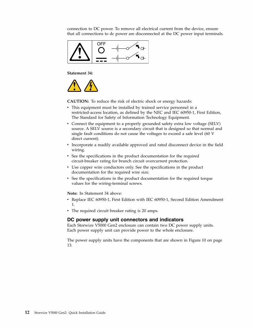
About this guide
This publication provides information that helps you install and initialize IBMStorwize V5000 Gen2 systems.
Who should use this guideThis guide is intended for installers of Storwize V5000 Gen2 systems.
Before configuring your system, ensure that you follow the procedures as listed. Besure to gather IP addresses that you will need before you begin the installation.
Storwize V5000 Gen2 library and related publicationsProduct manuals, other publications, and websites contain information that relatesto Storwize V5000 Gen2.
IBM Knowledge Center for Storwize V5000 Gen2
The information collection in the IBM Knowledge Center contains all of theinformation that is required to install, configure, and manage the system. Theinformation collection in the IBM Knowledge Center is updated between productreleases to provide the most current documentation. The information collection isavailable at the following website:
http://pic.dhe.ibm.com/infocenter/storwize/v5000_ic/index.jsp
Storwize V5000 Gen2 library
Unless otherwise noted, the publications in the library are available in Adobeportable document format (PDF) from a website.
www.ibm.com/e-business/linkweb/publications/servlet/pbi.wss
Click Search for publications to find the online publications you are interested in,and then view or download the publication by clicking the appropriate item.
Table 1 lists websites where you can find help, services, and more information.
Table 1. IBM websites for help, services, and information
Website Address
Directory of worldwide contacts http://www.ibm.com/planetwide
Support for Storwize V5000 (2077 or 2078) www.ibm.com/storage/support/storwize/v5000
Support for IBM System Storage® and IBM TotalStorage products www.ibm.com/storage/support/
Each of the PDF publications in the Table 2 on page xviii library is also available inthe IBM Knowledge Center by clicking the number in the “Order number” column:
© Copyright IBM Corp. 2016 xvii

Table 2. Storwize V5000 Gen2 library
Title Description Order number
IBM Storwize V5000 Gen2 QuickInstallation Guide
The guide provides instructions for unpacking yourorder and installing your system. The first chapterdescribes how to verify your order, identifyhardware components, and meet environmentalrequirements. The second chapter describes how toinstall the hardware and attach data cables andpower cords. The last chapter describes how toaccess the management GUI to initially configureyour system.
GC27-8581
IBM Storwize V5010 Installation Poster The installation poster provides an illustratedsequence of steps for installing the enclosures in arack and beginning the setup process for a StorwizeV5010 system.
GC27-8597
IBM Storwize V5020 Installation Poster The installation poster provides an illustratedsequence of steps for installing the enclosures in arack and beginning the setup process for a StorwizeV5020 system.
GC27-8598
IBM Storwize V5030 Installation Poster The installation poster provides an illustratedsequence of steps for installing the enclosures in arack and beginning the setup process for a StorwizeV5030 system.
GC27-8599
IBM Systems Safety Notices The guide contains translated caution and dangerstatements. Each caution and danger statement inthe Storwize V5000 Gen2 documentation has anumber that you can use to locate the correspondingstatement in your language in the IBM SystemsSafety Notices document.
G229-9054
IBM Storwize V5000 Gen2 Read FirstFlyer
This document introduces the major components ofthe Storwize V5000 Gen2 system and describes howto get started with the IBM Storwize V5000 Gen2Quick Installation Guide.
GI13-2860
IBM Statement of Limited Warranty(2078)
This multilingual document provides informationabout the IBM warranty for machine type 2078.
Part number: 00AK322
IBM License Agreement for MachineCode
This multilingual guide contains the LicenseAgreement for Machine Code for the StorwizeV5000 Gen2 product.
SC28-6872 (containsZ125-5468)
IBM documentation and related websites
Table 3 lists websites that provide publications and other information about theStorwize V5000 Gen2 or related products or technologies. The IBM Redbooks®
publications provide positioning and value guidance, installation andimplementation experiences, solution scenarios, and step-by-step procedures forvarious products.
Table 3. IBM documentation and related websites
Website Address
IBM Publications Center www.ibm.com/e-business/linkweb/publications/servlet/pbi.wss
IBM Redbooks publications www.redbooks.ibm.com/
xviii Storwize V5000 Gen2: Quick Installation Guide

Related accessibility information
To view a PDF file, you need Adobe Reader, which can be downloaded from theAdobe website:
www.adobe.com/support/downloads/main.html
How to order IBM publicationsThe IBM Publications Center is a worldwide central repository for IBM productpublications and marketing material.
The IBM Publications Center offers customized search functions to help you findthe publications that you need. Some publications are available for you to view ordownload at no charge. You can also order publications. The publications centerdisplays prices in your local currency. You can access the IBM Publications Centerthrough the following website:
www.ibm.com/e-business/linkweb/publications/servlet/pbi.wss
Related websitesThe following websites provide information about Storwize V5000 Gen2 or relatedproducts or technologies.
Type of information Website
Storwize V5000 Gen2 support www.ibm.com/storage/support/storwize/v5000
Technical support for IBM storageproducts
www.ibm.com/storage/support/
IBM Electronic Support registration www.ibm.com/support/electronicsupport
Sending your commentsYour feedback is important in helping to provide the most accurate and highestquality information.
To submit any comments about this book or any other Storwize V5000 Gen2documentation, send your comments by email to [email protected]. Includethe following information in your email:v Publication titlev Publication form numberv Page, table, or illustration numbers that you are commenting onv A detailed description of any information that should be changed
How to get information, help, and technical assistanceIf you need help, service, technical assistance, or just want more information aboutIBM products, you will find a wide variety of sources available from IBM to assistyou.
About this guide xix

Information
IBM maintains pages on the web where you can get information about IBMproducts and fee services, product implementation and usage assistance, break andfix service support, and the latest technical information. For more information,refer to Table 4.
Table 4. IBM websites for help, services, and information
Website Address
Directory of worldwide contacts http://www.ibm.com/planetwide
Support for Storwize V5000 (2077 or2078)
www.ibm.com/storage/support/storwize/v5000
Support for IBM System Storageand IBM TotalStorage products
www.ibm.com/storage/support/
Note: Available services, telephone numbers, and web links are subject to changewithout notice.
Help and service
Before calling for support, be sure to have your IBM Customer Number available.If you are in the US or Canada, you can call 1 (800) IBM SERV for help andservice. From other parts of the world, see http://www.ibm.com/planetwide forthe number that you can call.
When calling from the US or Canada, choose the storage option. The agent decideswhere to route your call, to either storage software or storage hardware, dependingon the nature of your problem.
If you call from somewhere other than the US or Canada, you must choose thehardware option when calling for assistance. When calling IBM for serviceregarding the product, follow these guidelines for the hardware :
Software optionIdentify the Storwize V5000 Gen2 product as your product and supplyyour customer number as proof of purchase. The customer number is a7-digit number (0000000 to 9999999) assigned by IBM when the product ispurchased. Your customer number should be located on the customerinformation worksheet or on the invoice from your storage purchase. Ifasked for an operating system, use Storage.
Hardware optionProvide the serial number and appropriate 4-digit machine type. ForStorwize V5000, the machine type is 2077 or 2078.
In the US and Canada, hardware service and support can be extended to 24x7 onthe same day. The base warranty is 9x5 on the next business day.
Getting help online
You can find information about products, solutions, partners, and support on theIBM website.
To find up-to-date information about products, services, and partners, visit the IBMwebsite at www.ibm.com/storage/support/storwize/v5000.
xx Storwize V5000 Gen2: Quick Installation Guide

Before you call
Make sure that you have taken steps to try to solve the problem yourself beforeyou call.
Some suggestions for resolving the problem before calling IBM Support include:v Check all cables to make sure that they are connected.v Check all power switches to make sure that the system and optional devices are
turned on.v Use the troubleshooting information in your system documentation. The
troubleshooting section of the information center contains procedures to helpyou diagnose problems.
v Go to the IBM Support website at www.ibm.com/storage/support/storwize/v5000 to check for technical information, hints, tips, and new device drivers orto submit a request for information.
Using the documentation
Information about your IBM storage system is available in the documentation thatcomes with the product.
That documentation includes printed documents, online documents, readme files,and help files in addition to the information center. See the troubleshootinginformation for diagnostic instructions. The troubleshooting procedure mightrequire you to download updated device drivers or software. IBM maintains pageson the web where you can get the latest technical information and downloaddevice drivers and updates. To access these pages, go to www.ibm.com/storage/support/storwize/v5000 and follow the instructions. Also, some documents areavailable through the IBM Publications Center.
Sign up for the Support Line Offering
If you have questions about how to use and configure the machine, sign up for theIBM Support Line offering to get a professional answer.
The maintenance supplied with the system provides support when there is aproblem with a hardware component or a fault in the system machine code. Attimes, you might need expert advice about using a function provided by thesystem or about how to configure the system. Purchasing the IBM Support Lineoffering gives you access to this professional advice while deploying your system,and in the future.
Contact your local IBM sales representative or your support group for availabilityand purchase information.
About this guide xxi

xxii Storwize V5000 Gen2: Quick Installation Guide

Chapter 1. Before you begin the installation
Before you can begin installing your system, you must unpack and verify yourorder and make other preparations.
The Quick Installation Guide contains a set of instructions to help you unpack andinstall your system. The guide is divided into three chapters.1. The steps in Chapter 1, “Before you begin the installation” (the chapter you are
now reading) involve verifying your order, becoming familiar with thehardware component terminology, and ensuring that you have met theenvironmental requirements.
2. The steps in Chapter 2, “Installing the Storwize V5000 Gen2 hardware,” onpage 19 involve installing the hardware and attaching the data cables andpower cords.
3. Chapter 3, “Configuring the system,” on page 41 helps you create yourconfiguration file and access the management GUI. The management GUIguides you through the initial configuration process.
Important information:v This guide presumes that you have read the planning information regarding
your physical environment that is available from the IBM Knowledge Center forStorwize V5000 Gen2.
v Ensure that any cables that you are supplying are available for installation.
Table 5 lists the steps for each scenario.
Table 5. Steps for different installation scenarios for Storwize V5000 Gen2 systems
New system Existing system
Control enclosure only Control enclosure and oneor more expansionenclosures
Adding expansionenclosures
Adding a control enclosureand expansion enclosures(Storwize V5030 only)
“Reviewing your packingslip” on page 5
“Reviewing your packingslip” on page 5
“Reviewing your packingslip” on page 5
“Reviewing your packingslip” on page 5
“Identify the hardwarecomponents” on page 7
“Identify the hardwarecomponents” on page 7
“Identify the hardwarecomponents” on page 7
“Identify the hardwarecomponents” on page 7
“Verify environmentalrequirements” on page 16
“Verify environmentalrequirements” on page 16
“Verify environmentalrequirements” on page 16
“Verify environmentalrequirements” on page 16
“Review enclosure locationguidelines” on page 16
“Review enclosure locationguidelines” on page 16
“Review enclosure locationguidelines” on page 16
“Review enclosure locationguidelines” on page 16
“Installing support rails forStorwize V5000 Gen2systems” on page 19
“Installing support rails forStorwize V5000 Gen2systems” on page 19
“Installing support rails forStorwize V5000 Gen2systems” on page 191
“Installing support rails forStorwize V5000 Gen2systems” on page 192
“Installing enclosures forStorwize V5000 Gen2systems” on page 23
“Installing enclosures forStorwize V5000 Gen2systems” on page 23
“Installing enclosures forStorwize V5000 Gen2systems” on page 231
“Installing enclosures forStorwize V5000 Gen2systems” on page 232
“Connecting Ethernetcables to node canisters” onpage 30
“Connecting SAS cables toStorwize V5000 Gen2expansion enclosures” onpage 24
“Connecting SAS cables toStorwize V5000 Gen2expansion enclosures” onpage 241
“Connecting SAS cables toStorwize V5000 Gen2expansion enclosures” onpage 241
© Copyright IBM Corp. 2016 1

Table 5. Steps for different installation scenarios for Storwize V5000 Gen2 systems (continued)
New system Existing system
Control enclosure only Control enclosure and oneor more expansionenclosures
Adding expansionenclosures
Adding a control enclosureand expansion enclosures(Storwize V5030 only)
“Connecting Fibre Channelcables to a Fibre Channelhost interface adapter” onpage 35
“Connecting Fibre Channelcables to a 10 GbpsiSCSI-FCoE 4-port hostinterface adapter” on page33
“Connecting Ethernetcables to node canisters” onpage 30
“Powering on the system”on page 391
“Connecting Ethernetcables to node canisters” onpage 302
“Powering on the system”on page 39
“Connecting Ethernetcables to node canisters” onpage 30
“Adding an expansionenclosure to an existingsystem” on page 45
“Connecting Fibre Channelcables to a Fibre Channelhost interface adapter” onpage 35
Chapter 3, “Configuring thesystem,” on page 41
“Powering on the system”on page 39
“Powering on the system”on page 39
Chapter 3, “Configuring thesystem,” on page 41
“Adding a controlenclosure to an existingStorwize V5030 system” onpage 46
1Complete these steps for each expansion enclosure that you add.2Complete these steps for each control enclosure and expansion enclosure that you add.
Be familiar with the following informationv See “Caution notices for the Storwize V5000 Gen2” on page x and “Danger
notices for Storwize V5000 Gen2” on page xii for a summary of the situationsthat can be potentially hazardous to you. Before installing, read and understandthe following caution and danger statements.
2 Storwize V5000 Gen2: Quick Installation Guide

v Use safe practices when lifting. The fully populated enclosure weighs about 26kg (57 lbs). At least two people are required to lift and install the enclosure intothe rack or to remove an enclosure from the rack.The fully populated enclosureweighs about 37 kg (82 lbs). At least three people are required to lift and installthe enclosure into the rack or to remove an enclosure from the rack.CAUTION:Use safe practices when lifting.
svc00146
18-32 kg (39.7-70.5 lbs) 32-55 kg (70.5-121.2 lbs) 55 kg ( 121.2 lbs)
(27)
Also keep in mind that a rack full of equipment is extremely heavy.
DANGER: Heavy equipment–personal injury or equipment damage mightresult if mishandled. (D006)
v The following general precautions should be observed, even though thepower-on steps differ slightly from the directions that you will follow for thisproduct:
Chapter 1. Before you begin the installation 3

DANGER
When working on or around the system, observe the following precautions:
Electrical voltage and current from power, telephone, and communicationcables are hazardous. To avoid a shock hazard:
– If IBM supplied a power cord(s), connect power to this unit only withthe IBM provided power cord. Do not use the IBM provided power cordfor any other product.
– Do not open or service any power supply assembly.
– Do not connect or disconnect any cables or perform installation,maintenance, or reconfiguration of this product during an electricalstorm.
– The product might be equipped with multiple power cords. To removeall hazardous voltages, disconnect all power cords.
– Connect all power cords to a properly wired and grounded electricaloutlet. Ensure that the outlet supplies proper voltage and phase rotationaccording to the system rating plate.
– Connect any equipment that will be attached to this product to properlywired outlets.
– When possible, use one hand only to connect or disconnect signal cables.
– Never turn on any equipment when there is evidence of fire, water, orstructural damage.
– Disconnect the attached power cords, telecommunications systems,networks, and modems before you open the device covers, unlessinstructed otherwise in the installation and configuration procedures.
– Connect and disconnect cables as described in the following procedureswhen installing, moving, or opening covers on this product or attacheddevices.
To disconnect:
1. Turn off everything (unless instructed otherwise).
2. Remove the power cords from the outlets.
3. Remove the signal cables from the connectors.
4. Remove all cables from the devices.
To connect:
1. Turn off everything (unless instructed otherwise).
2. Attach all cables to the devices.
3. Attach the signal cables to the connectors.
4. Attach the power cords to the outlets.
5. Turn on the devices.
– Sharp edges, corners and joints might be present in and around thesystem. Use care when handling equipment to avoid cuts, scrapes andpinching. (D005)
Tools needed
A flat-blade screwdriver with a 7 mm (1/4 inch) head is the only tool needed forinstallation.
4 Storwize V5000 Gen2: Quick Installation Guide

Reviewing your packing slipAfter you open your shipment, you must verify the contents against the packingslip.
In each box, locate the packing slip. Verify that the items listed in the packing slipmatch what is in the box, and that any optional items that you ordered areincluded in the list. Your shipment might contain extra items, depending on theorder.
Note: If you purchased your equipment through a reseller, some of the optionsmight be preinstalled. Contact your supplier for details.
Use the following checklist to check off the items in your order as you verify thatthey are included in your shipment.__ v Table 6 summarizes the machine types and models of the Storwize V5000
Gen2 control enclosures.
Table 6. Storwize V5000 Gen2 control enclosures
IBM Storwize V5000 Gen2 ModelMachine
type / modelWarranty Description
IBM Storwize V5010
2077–112 1 year 12-slot Control enclosure for 3.5-inchdrives
2077-124 1 year 24-slot Control enclosure for 3.5-inchdrives
2078–112 3 years 12-slot Control enclosure for 2.5-inchdrives
2078–124 3 years 24-slot Control enclosure for 2.5-inchdrives
IBM Storwize V5020
2077–212 1 year 12-slot Control enclosure for 3.5-inchdrives
2077–224 1 year 24-slot Control enclosure for 3.5-inchdrives
2078 –212 3 years 12-slot Control enclosure for 2.5-inchdrives
2078 –224 3 years 24-slot Control enclosure for 2.5-inchdrives
IBM Storwize V5030
2077–312 1 year 12-slot Control enclosure for 3.5-inchdrives
2077–324 1 year 24-slot Control enclosure for 3.5-inchdrives
2078–312 3 years 12-slot Control enclosure for 2.5-inchdrives
2078–324 3 years 24-slot Control enclosure for 2.5-inchdrives
__ v All Storwize V5000 Gen2 systems support the expansion enclosures that arelisted in Table 7 on page 6.
Chapter 1. Before you begin the installation 5

Table 7. Storwize V5000 Gen2 expansion enclosures
IBM Storwize V5000 Gen2 ModelMachine
type / modelWarranty Description
v Storwize V5010
v Storwize V5020
v Storwize V5030
2077-12F 1 year 12-slot Expansion enclosure for 3.5-inchdrives
2077-24F 1 year 24-slot Expansion enclosure for 3.5-inchdrives
2078-12F 3 years 12-slot Expansion enclosure for 2.5-inchdrives
2078-24F 3 years 24-slot Expansion enclosure for 2.5-inchdrives
__ v Rack-mounting hardware kit:__ – Two rails (right and left assembly)__ – Two rail springs__ – Two sets of rail-mount screws and alternative rail-mount pins (large and
small) for non-IBM racks__ v Two power cords for connection to rack-mounted power distribution units__ v Drive bay blanking plates (installed in the enclosure)
Options applicable to control enclosures__ v Cache memory upgrade (16 GB for Storwize V5020 and 32 GB for Storwize
V5030)__ v Fibre Channel cables__ v SAS cables__ v Drives__ v Power cords for connection to wall sockets__ v Four-port 16 Gbps Fibre Channel HBA__ v Four-port 10 Gbps Ethernet Adapter (iSCSI, FCoE)__ v Four-port 12 Gbps SAS HBA__ v Four-port 1 Gbps Ethernet Adapter (iSCSI)__ v DC power supply (if applicable to the feature number ordered)
Options applicable to expansion enclosures__ v Expansion enclosure attachment cables__ v Drives__ v DC power supply (if applicable to the feature number ordered)__ v Power cords for connection to wall sockets
6 Storwize V5000 Gen2: Quick Installation Guide

Identify the hardware componentsThe following graphics identify the hardware components and port locations forthe control enclosure and expansion enclosure on Storwize V5000 Gen2 systems.
Control enclosure components
The following figures show the rear view of the control enclosures on StorwizeV5000 Gen2 systems. The location of the power supply units and node canistersare also shown.
Figure 1 shows the Storwize V5010 control enclosure.
Figure 2 shows a rear view of the Storwize V5020 node.
Figure 3 shows a rear view of the Storwize V5030 node.
Data ports
The following figures show the rear view of the control enclosures on StorwizeV5000 Gen2 systems. The location of the ports are shown.v ▌T▐ Technician portv ▌1▐ Ethernet port 1v ▌2▐ Ethernet port 2
tb500023
Figure 1. Storwize V5010 control enclosure
tb500024
Figure 2. Storwize V5020 control enclosure
tb500022
Figure 3. Storwize V5030 control enclosure
Chapter 1. Before you begin the installation 7

v ▌2/T▐ Ethernet port 2/Technician portv ▌3▐ SAS ports
Figure 4 shows the Storwize V5010 control enclosure.
Figure 5 shows the data ports on the back of the Storwize V5020 node.
Figure 6 shows the data ports on the back of a Storwize V5030 node.
tb5
00
02
6
1 32/T
Figure 4. Data ports on the rear of the Storwize V5010 control enclosure
tb500027
1 32/T
Figure 5. Data ports on the rear of the Storwize V5020 control enclosure
tb500025
T 21 3
Figure 6. Data ports on the rear of the Storwize V5030 control enclosure
8 Storwize V5000 Gen2: Quick Installation Guide

Expansion enclosure components
Figure 7 shows the location of the power supply units and expansion canisters.v ▌1▐ Expansion canistersv ▌2▐ Power supply units
Figure 8 shows the LEDs and SAS port locations from the rear view of anexpansion canister.v ▌1▐ LEDsv ▌2▐ SAS ports
Each canister has two SAS ports that are numbered 1 on the left and 2 on the right.Port 1 is used to connect to a SAS expansion port on a node canister or port 2 ofanother expansion canister.
Support rails and enclosures
Storwize V5000 Gen2 systems use the same rails and enclosures for both controland expansion enclosures. All Storwize V5000 Gen2 models use the sameexpansion enclosure.v The ledge on the inside of each rail supports the entire length of an enclosure.v The enclosure support rails capture the left and right rear edges of an inserted
enclosure. This prevents the installed enclosure bouncing when the rack issubjected to quake or vibration.
v The enclosure support rails adjust to fit racks from 595 mm to 755 mm deep,measured between the front and rear rack rails.
fab10006
2
1
IN
DC
!
OK
IN
DC
!
OK
Figure 7. Rear view of a Storwize V5000 Gen2 expansion enclosure
fab10009
1 2
Figure 8. SAS ports and LEDs in rear view of a Storwize V5000 Gen2 expansion canister
Chapter 1. Before you begin the installation 9

Direct current power supply unitsWhen feature code AHPB is used, a direct current (DC) power supply can beinstalled in a Storwize V5000 Gen2 enclosure.
This section describes the additional information you need to know when usingthe DC power models.
DANGER
Hazardous voltage, current, or energy levels are present inside any componentthat has this label attached. Do not open any cover or barrier that containsthis label. (L001)
DANGER
fab10053
Figure 9. Enclosure support rails on Storwize V5000 Gen2
10 Storwize V5000 Gen2: Quick Installation Guide

When working on or around the system, observe the following precautions:
Electrical voltage and current from power, telephone, and communicationcables are hazardous. To avoid a shock hazard:
v If IBM supplied a power cord(s), connect power to this unit only with theIBM provided power cord. Do not use the IBM provided power cord forany other product.
v Do not open or service any power supply assembly.
v Do not connect or disconnect any cables or perform installation,maintenance, or reconfiguration of this product during an electrical storm.
v The product might be equipped with multiple power cords. To remove allhazardous voltages, disconnect all power cords.
v Connect all power cords to a properly wired and grounded electrical outlet.Ensure that the outlet supplies proper voltage and phase rotation accordingto the system rating plate.
v Connect any equipment that will be attached to this product to properlywired outlets.
v When possible, use one hand only to connect or disconnect signal cables.
v Never turn on any equipment when there is evidence of fire, water, orstructural damage.
v Disconnect the attached power cords, telecommunications systems,networks, and modems before you open the device covers, unlessinstructed otherwise in the installation and configuration procedures.
v Connect and disconnect cables as described in the following procedureswhen installing, moving, or opening covers on this product or attacheddevices.
To disconnect:
1. Turn off everything (unless instructed otherwise).
2. Remove the power cords from the outlets.
3. Remove the signal cables from the connectors.
4. Remove all cables from the devices.
To connect:
1. Turn off everything (unless instructed otherwise).
2. Attach all cables to the devices.
3. Attach the signal cables to the connectors.
4. Attach the power cords to the outlets.
5. Turn on the devices.
v Sharp edges, corners and joints may be present in and around the system.Use care when handling equipment to avoid cuts, scrapes and pinching.(D005)
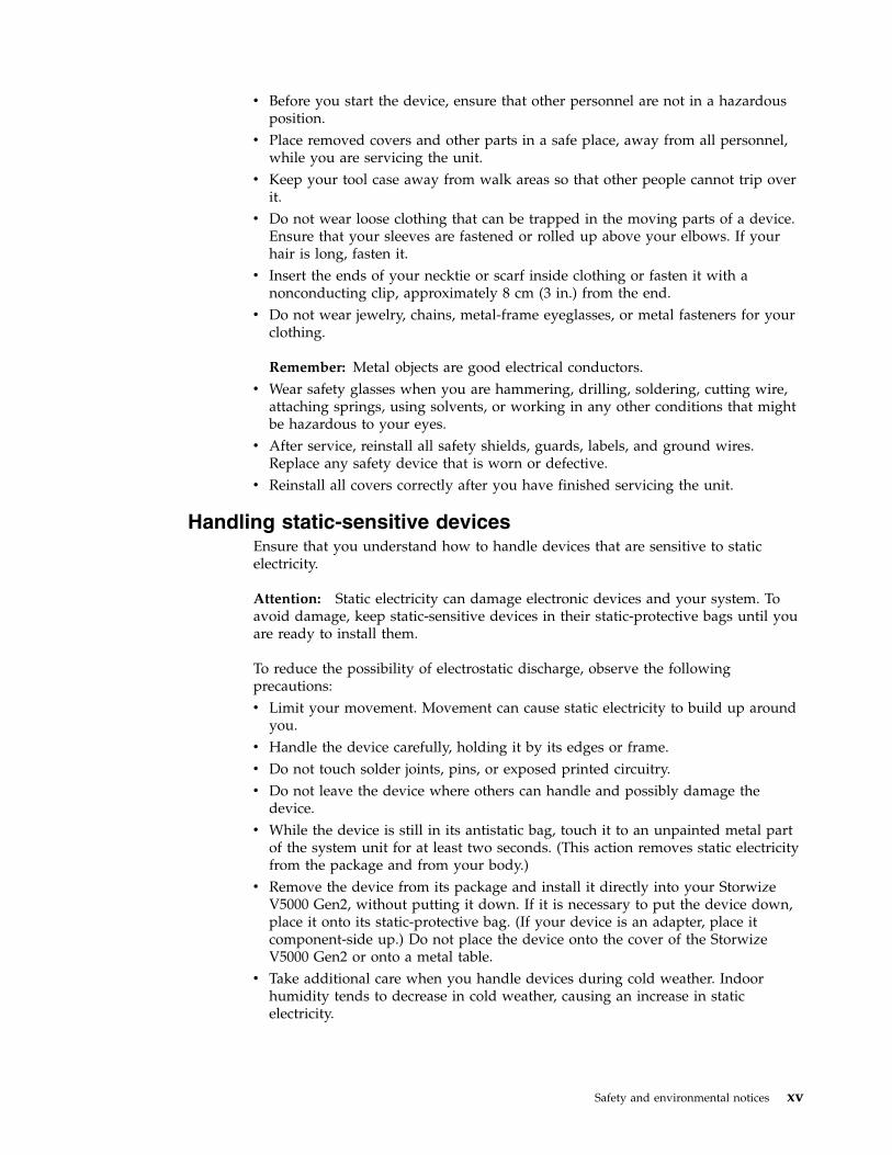
Statement 19:
CAUTION: The power-control button on the device does not turn off the electricalcurrent supplied to the device. The device also might have more than one
Chapter 1. Before you begin the installation 11
connection to DC power. To remove all electrical current from the device, ensurethat all connections to dc power are disconnected at the DC power input terminals.
OFF
Statement 34:
CAUTION: To reduce the risk of electric shock or energy hazards:v This equipment must be installed by trained service personnel in a
restricted-access location, as defined by the NEC and IEC 60950-1, First Edition,The Standard for Safety of Information Technology Equipment.
v Connect the equipment to a properly grounded safety extra low voltage (SELV)source. A SELV source is a secondary circuit that is designed so that normal andsingle fault conditions do not cause the voltages to exceed a safe level (60 Vdirect current).
v Incorporate a readily available approved and rated disconnect device in the fieldwiring.
v See the specifications in the product documentation for the requiredcircuit-breaker rating for branch circuit overcurrent protection.
v Use copper wire conductors only. See the specifications in the productdocumentation for the required wire size.
v See the specifications in the product documentation for the required torquevalues for the wiring-terminal screws.
Note: In Statement 34 above:v Replace IEC 60950-1, First Edition with IEC 60950-1, Second Edition Amendment
1.v The required circuit breaker rating is 20 amps.
DC power supply unit connectors and indicatorsEach Storwize V5000 Gen2 enclosure can contain two DC power supply units.Each power supply unit can provide power to the whole enclosure.
The power supply units have the components that are shown in Figure 10 on page13.
12 Storwize V5000 Gen2: Quick Installation Guide

v ▌1▐ Release tabv ▌2▐ Handlev ▌3▐ Power supply LED indicatorsv ▌4▐ DC power cable connector
Each power supply also contains fans that cool the enclosure. Cool air is drawn inthrough the front of the enclosure. The air passes over the drives, node canisters,and power supplies. The warmed air is ejected through the rear of each powersupply. For optimal cooling, do not obstruct the airflow and ensure that allenclosure components or fillers are installed while the system is operational.
DC power supply LED indicators
Each power supply unit has four LED indicators. Table 8 summarizes their possiblevalues and meaning.
The LEDs have a comparable meaning to the LEDs on the AC power supply.Problem diagnosis and service procedures are the same. For details, see “Poweringon the system” on page 39.
Table 8. DC power supply LED indicators
Name Label Color State Description
Input status IN Green OFF No input power detected.
ON DC input power detected.
Outputstatus
Green OFF PSU is not providing DC output power.
ON PSU is providing DC output power.
Fault Amber OFF No fault detected.
ON PSU fault was detected.
BLINK PSU is being identified. A fault might have been detected.
(None)
OK
Blue N/A Not used.
Connecting a DC power supply to a DC power sourceA Storwize V5000 Gen2 enclosure that is DC powered contains two DC powersupply units (PSUs). Each unit must be connected to a suitable -48V DC powersource. To provide redundancy in a power circuit failure, connect the two PSUs todifferent DC power sources.
v3500191
1 2 3 4
Figure 10. DC power supply unit connectors and indicators
Chapter 1. Before you begin the installation 13

Use the supplied cables to connect the DC PSUs to the power sources. Use onlythe IBM supplied DC power cable (IBM part number 00AR087) to connect the unitto a DC power source.
Each PSU cable must be protected by a 20A circuit breaker. These instructionsassume that the circuit breaker is separate from the DC power distribution unit.Refer to the DC power distribution unit documentation and the circuit breakerdocumentation for details. Follow the instructions that are given there forconnecting the circuit breaker to the power distribution unit and for connecting theDC power cable to the circuit breaker.
One end of the cable ends in a plug that fits the DC PSU. At the other end of thecable, each individual wire ends with a 6 mm diameter ring terminal that isdesigned to fit an M6 stud. Provide adequate strain relief after you attach the ringterminals to the power source. Table 9 lists the wire colors.
Table 9. DC cable wire color coding
Color Function
Blue Return
Green / Yellow Ground
Brown -48V
The DC power cable is 4 m long. Connect it to the DC power source before youconnect it to the PSU. The PSU does not have a power switch, so its outputs andthe enclosure become live as soon as power is connected.
The supplied power must meet the input requirements that are listed in Table 10.
Table 10. DC power supply input requirements
Requirement Min Max
Voltage (V DC) -48 -60
Instantaneous (V DC for < 1 second) -36 -75
Inrush current at initial turn on (-48V DC) 34 A
Out of spec time before power off is signaled 5 ms
The connection to the DC power source must be made by trained servicepersonnel. Ensure that the connection is made in accordance with all therequirements of the equipment that is being used.
The DC power cable must be totally contained in a single rack and must notextend outside the rack to another rack.
If it is necessary to replace the ring terminals with a different connector, choose asuitably sized and rated UL-listed connector that is appropriate for the wire gaugeand available current. Install the ring terminals according to the instructionsprovided by the manufacturer.
Direct current power replaceable unitsThe DC power supply model has two replaceable units.
14 Storwize V5000 Gen2: Quick Installation Guide

Table 11. Direct current power replaceable units
Description FRU part number Customer replaced
Direct current power supply 00AR231 Y
Direct current power cable 00AR087 Y
The procedure to remove and replace the DC power supply unit is the same as theAC power supply procedure.
When replacing the DC power cable, follow the instructions for disconnectingcables from the DC power distribution unit.
Chapter 1. Before you begin the installation 15

Verify environmental requirementsThe environmental and electrical requirements for the physical site must be met toensure that your system works reliably.
Before installing a Storwize V5000 Gen2 system, you must verify that adequatespace in a suitable rack is available. You must also ensure that the requirements forpower and environmental conditions are met.
This guide assumes that you have completed the physical planning for theenvironment of your system. If you have not done the environmental planning foryour system, see the “Storwize V5000 Gen2 physical installation planning” topic inthe IBM Knowledge Center for Storwize V5000 Gen2.
Review enclosure location guidelinesBefore you install the enclosures, you must be familiar with these enclosurelocation guidelines.
Installing a control enclosure only
If you are installing a control enclosure only, follow these guidelines.v Position the enclosure in the rack so that you can easily view it and access it for
servicing.v Locate the enclosure low enough for the rack to remain stable.v Ensure that you provide a way for two or more people to install and remove the
enclosure.
Installing a control enclosure and one or more expansionenclosures
If you are installing a control enclosure plus one or more expansion enclosures,follow these guidelines.v Each Storwize V5000 enclosure to be installed requires 2U of rack space.v Each assembled enclosure weighs more than 18 kg. Provide sufficient space at
the front of the rack for two persons to carry the enclosure safely.v Install all enclosures that constitute one system in contiguous positions in a rack.
Place the control enclosure in the middle of the rack.v Storwize V5010 and Storwize V5020 control enclosures systems can support up
to 10 expansion enclosures on one chain. Storwize V5030 systems can supporttwo chains and each chain can support up to 10 expansions enclosures.
v If a rack is to be only partially filled, install the enclosures low enough for therack to remain stable and enable easy access to the enclosures for servicing.
Adding an expansion enclosure chain to an existing system
If you are adding an expansion enclosure chain to an existing Storwize V5030system, follow these guidelines.v You do not need to power off the system. You can add an expansion enclosure
while the system is operational.v Add the first expansion enclosure directly below the control enclosure.v Add the second expansion enclosure directly above the control enclosure.v Add the third expansion enclosure directly below the first.
16 Storwize V5000 Gen2: Quick Installation Guide

v Add the fourth expansion directly above the second, and so on.
Chapter 1. Before you begin the installation 17

18 Storwize V5000 Gen2: Quick Installation Guide

Chapter 2. Installing the Storwize V5000 Gen2 hardware
After verifying that you have all of the hardware components that you require,you can install them.
You have completed the initial steps of verifying the shipping contents andbecoming familiar with the hardware components. You have verified that thepower and environmental requirements are met and have planned the location ofthe enclosures. You are now ready to begin installing the hardware componentsand connecting the data cables and power cords.
Installing support rails for Storwize V5000 Gen2 systemsStorwize V5000 Gen2 systems use the same rails for control and expansionenclosures. Before you install a control or expansion enclosure, you must firstinstall the support rails for it.
Procedure
To install the support rails for an enclosure, complete the following steps.1. Locate the control enclosure rails (Figure 11). The rail assembly consists of two
rails that must be installed in the rack cabinet.
2. Install a spring on each rail.a. Extend the rail to its full length.b. Push one looped end of a spring over one stud on the inside of the rail.
(See Figure 12 on page 20.)c. Stretch the spring slightly and push the other looped end of the spring
onto the other stud on the inside of the rail.
fab10051
Figure 11. Control enclosure support rails
© Copyright IBM Corp. 2016 19

3. Working at the front of the rack cabinet, identify the two standard rack units(2U) of space in the rack into which you want to install the support rails.Figure 13 on page 21 shows two rack units with the front mounting holesidentified.
fab10050
Figure 12. Installing the rail spring
20 Storwize V5000 Gen2: Quick Installation Guide

v ▌1▐ Upper rail-mounting bracket pinv ▌2▐ Lower rail-mounting bracket pinv ▌3▐ Rack mounting screw hole
4. Ensure that the appropriate bracket pins are installed in the front and rearbracket of each rail. Each rail comes with four medium pins preinstalled (twoin the front bracket and two in the rear bracket). Large and small pins areprovided separately. Use the pins that are appropriate for the mounting holesin your rack (see Table 12).
Table 12. Selecting bracket pins for your rack
Mounting holes Bracket pins
Round,unthreaded
Use the preinstalled medium pins.
Round, threaded Unscrew the medium pins and replace with the smaller pins suppliedwith the rails.
Square Unscrew the medium pins and replace with the large pins supplied withthe rails.
5. At each end of the rail, grasp the tab and pull firmly to open the hingebracket. (See Figure 14 on page 22.)
1
2
3v3500162
Figure 13. Hole locations in the front of the rack
Chapter 2. Installing the Storwize V5000 Gen2 hardware 21

6. Align the holes in the rail bracket with the holes on the front and rear rackcabinet flanges. Ensure that the rails are aligned on the inside of the rackcabinet.
7. On the rear of the rail, press the two bracket pins into the holes in the rackflanges.
8. Close the rear hinge bracket to secure the rail to the rack cabinet flange. (SeeFigure 15.)
9. On the front of the rail, press the two bracket pins into the holes in the rackflanges.
10. Close the front hinge bracket to secure the rail to the rack cabinet flange.Figure 15 shows an example.
11. Secure the rear of the rail to the rear rack flange with an M5 screw.12. Repeat the steps to secure the opposite rail to the rack cabinet.13. Repeat the procedure to install rails for each additional control enclosure.
4
tb500045
Figure 14. Opening the hinge brackets
4
33
2
11
tb500051
Figure 15. Closing the hinge brackets
22 Storwize V5000 Gen2: Quick Installation Guide

Installing enclosures for Storwize V5000 Gen2 systemsFollowing your enclosure location plan, install the control enclosure (andoptionally, one or more expansion enclosures).
About this task
CAUTION:
v To lift and install the enclosure into the rack requires at least two people.
v To lift a control enclosure with drives installed requires at least three people.
v Load the rack from the bottom up to ensure rack stability. Empty the rackfrom the top down.
Procedure
To install an enclosure, complete the following steps.1. On either side of the drive assemblies, remove the enclosure end caps by
grasping the handle and pulling the bottom of the end cap free, then clearingthe tab on the top of the enclosure. (See Figure 16.)
2. Align the enclosure with the front of the rack cabinet.3. Carefully slide the enclosure into the rack along the rails until the enclosure is
fully inserted (see Figure 17 on page 24).
Note: The rails are not designed to hold an enclosure that is partially inserted.The enclosure must always be in a fully inserted position.
fab10020
Figure 16. Removing enclosure end caps
Chapter 2. Installing the Storwize V5000 Gen2 hardware 23

4. Secure the enclosure with a screw in the rack mounting screw hole.5. Reinstall the left and right end caps. (See Figure 17.) The left end cap has
indicator windows that align with the status LEDs (light-emitting diodes) onthe edge of the enclosure.a. Ensure that the serial number of the end cap matches the serial number on
the rear of the enclosure.b. Fit the slot on the top of the end cap over the tab on the chassis flange.c. Rotate the end cap down until it snaps into place.d. Ensure that the inside surface of the end cap is flush with the chassis.
Connecting SAS cables to Storwize V5000 Gen2 expansion enclosuresIf you have installed expansion enclosures, you must connect them to a StorwizeV5000 Gen2 control enclosure.
About this task
This task applies if you are installing one or more expansion enclosures.
The number of SAS chains and enclosures varies per each type of system, asshown in Table 13 on page 25.
v3500047
Figure 17. Inserting the enclosure
24 Storwize V5000 Gen2: Quick Installation Guide

Table 13. Summary of SAS chains and enclosures
System Expansionports
Number ofSAS chainssupported
Controlenclosuresper system
Expansionenclosuresper chain
MaximumNumber ofEnclosures
StorwizeV5010 andStorwizeV5020
Port 1 only 1 1 10 11
StorwizeV5030
Port 1 andPort 2
2 1 10 21
Each set of expansion enclosures is connected together sequentially through the INand OUT SAS ports, forming a chain with a control enclosure at the end of thechain.
Note: When connecting SAS cables between enclosures, you must follow a list ofguidelines to ensure that your configuration is valid. Do not begin connecting thecables until you have read “SAS cabling guidelines” on page 29.
Procedure
To install the cables, complete the following steps.1. Using the supplied SAS cables, connect the control enclosure to the expansion
enclosure at rack position 1, as shown in the following figures.a. Connect SAS port 1 of the left node canister in the control enclosure to SAS
port 1 of the left expansion canister in the first expansion enclosure.b. Connect SAS port 1 of the right node canister in the control enclosure to
SAS port 1 of the right expansion canister in the first expansion enclosure.Figure 18 on page 26 shows how to connect SAS cables on a Storwize V5010system.
Chapter 2. Installing the Storwize V5000 Gen2 hardware 25

Figure 19 on page 27 shows how to connect SAS cables on a Storwize V5020system.
tb500007
Figure 18. Connecting the SAS cables to a Storwize V5010 system
26 Storwize V5000 Gen2: Quick Installation Guide

Figure 20 on page 28 shows how to connect SAS cables on a Storwize V5030system. In this figure, two expansion chains are connected to the StorwizeV5030 system.
tb5
00
00
8
Figure 19. Connecting the SAS cables to a Storwize V5020 system
Chapter 2. Installing the Storwize V5000 Gen2 hardware 27

2. To add a second expansion chain to the Storwize V5030 control enclosure, usethe supplied SAS cables to connect the control enclosure to the expansionenclosure at rack position 2, as shown in Figure 20.
Note: Storwize V5010 and Storwize V5020 systems support only one expansionchain.a. Connect SAS port 2 of the left node canister in the control enclosure to SAS
port 1 of the left expansion canister in the second expansion enclosure.
tb5
00
00
9
Figure 20. Connecting the SAS cables to a Storwize V5030 system
28 Storwize V5000 Gen2: Quick Installation Guide

b. Connect SAS port 2 of the right node canister in the control enclosure toSAS port 1 of the right expansion canister in the second expansionenclosure.
3. If more expansion enclosures are installed, connect each one to the previousexpansion enclosure in a chain; use two Mini SAS HD to Mini SAS HD cables,as shown in Figure 20 on page 28.
4. If two control enclosures are installed (Storwize V5030 only), repeat this cablingprocedure on the second control enclosure and its expansion enclosures.
SAS cabling guidelinesWhen connecting SAS cables between enclosures, you must follow a list ofguidelines to ensure that your configuration is valid.
Orienting the connector
When inserting SAS cables, make sure the connector (Figure 21) is orientedcorrectly.v The orientation of the connector must match the orientation of the port before
you push the connector into the port. The cable connector and socket are keyed,and it is important that you have proper alignment of the keys when the cable isinserted.
v The blue pull tab must be below the connector.v Insert the connector gently until it clicks into place. If you feel resistance, the
connector is probably oriented the wrong way. Do not force it.v When inserted correctly, the connector can only be removed by pulling the tab.v When both ends of a SAS cable are inserted correctly, the green link LEDs next
to the connected SAS ports are lit.
Connecting SAS cablesv No more than 10 expansion enclosures can be chained to SAS port 1 of a
Storwize V5010, Storwize V5020, or Storwize V5030 node canister. The expansionenclosures in this chain should be installed below the control enclosure.
v For Storwize V5030 systems only, no more than 10 expansion enclosures can bechained to SAS port 2 of a node canister. The expansion enclosures in this chainshould be installed above the control enclosure.
v3500179
Figure 21. SAS cable connectors
Chapter 2. Installing the Storwize V5000 Gen2 hardware 29

v No cable can be connected between a port on a left canister and a port on aright canister.
v A cable must not be connected between ports in the same enclosure.v A connected port on the node canister must connect to a single port on an
expansion canister. Cables that split the connector out into separate physicalconnections are not supported.
v Attach cables serially between enclosures; do not skip an enclosure.v The last enclosure in a chain must not have cables in port 2 of canister 1 and
port 2 of canister 2.v Ensure that cables are installed in an orderly way to reduce the risk of cable
damage when replaceable units are removed or inserted.
Refer to “Connecting SAS cables to Storwize V5000 Gen2 expansion enclosures” onpage 24 for examples of SAS cable connections on each Storwize V5000 Gen2system.
Connecting Ethernet cables to node canistersThe control enclosures on Storwize V5000 Gen2 systems have several Ethernetports on the rear of each node canister. The ports provide access to systemmanagement facilities and can also provide iSCSI connectivity. The number ofports and their initial function differ across each of the Storwize V5000 Gen2systems.
Procedure
To install the Ethernet cables, complete the following steps.1. If you have a Storwize V5010 or Storwize V5020 system, complete the following
steps.a. Identify the location and function of the Ethernet ports on your system;
refer to Figure 22 on page 31 and Figure 23 on page 31.v Port 1 can be used to provide Ethernet connections; in the figures, port 1
is identified by the green cable.v Port 2 serves as the technician port when the system is initially set up or
when service is needed. In the figures, port 2 is identified by the bluecable. After the system initializes, port 2 can also be used for iSCSIconnectivity or IP replication.
Note: Do not connect port 2 to a network switch until the systeminitialization or service is complete. After the system initializes, thetechnician port is automatically disabled and port 2 can be used forEthernet connectivity. However, when port 2 is used to perform systemservice, you must first enter the satask chserviceip -techport disablecommand to disable the technician port. You can then use port 2 toprovide additional Ethernet connectivity.
b. Connect Ethernet port 1 of each node canister in the system to the IPnetwork that will provide a connection to the system managementinterfaces.Figure 22 on page 31 shows the Ethernet cabling and the ports on the backof a Storwize V5010 system.
30 Storwize V5000 Gen2: Quick Installation Guide

Figure 23 shows the Ethernet cabling and the ports on the back of aStorwize V5020 system.
c. Optionally, connect Ethernet port 2 of each node canister in the system to asecond IP network, as shown by the blue cable connection in Figure 22 andFigure 23. This second port can be used to provide a redundant connectionto the system management interfaces; it can also be used for iSCSIconnectivity to the system by hosts on the network.
Note: On Storwize V5010 and Storwize V5020 systems, the second Ethernetport is also used as the technician port. Do not connect Ethernet port 2 tothe SAN until the management GUI setup wizard completes on each systemand the cluster is created. If you have to service your system, disconnectport 2 from the SAN before you enable port 2 to be the technician portagain.
2. If you have a Storwize V5030 system, complete the following steps.a. Identify the location and function of the Ethernet ports on your system;
refer to Figure 24 on page 32.v The technician port should only be used to initialize or service the
system. In Figure 24 on page 32, the technician port is identified by thegreen cable.
Note: Never use the technician port to provide an Ethernet connection tothe system. Do not connect the Ethernet technician port to a network
tb500011
Figure 22. Connecting the Ethernet cables to a Storwize V5010 system
tb500012
Figure 23. Connecting the Ethernet cables to a Storwize V5020 system
Chapter 2. Installing the Storwize V5000 Gen2 hardware 31

switch. The technician port must only be directly connected to a personalcomputer when initializing a system or servicing a node.
v Ethernet port 1 can be used to provide Ethernet connections. In thefigure, port 1 is identified by the blue cable.
v Ethernet port 2 can optionally be used to provide additional Ethernetconnections. In the figure, port 2 is identified by the red cable. Port 2 canalso be used for iSCSI connectivity or IP replication.
b. Connect Ethernet port 1 of each Storwize V5030 node canister in the systemto the IP network that will provide a connection to the system managementinterfaces. Figure 24 shows the port locations and Ethernet cabling on aStorwize V5030 node canister.
c. Optionally, connect Ethernet port 2 of each node canister in the system to asecond IP network, as shown by the red cable connection in Figure 24. Port2 can provide a redundant connection to the system management interfaces.Port 2 can also be used for iSCSI connectivity to the system by hosts on thenetwork. If more than one control enclosure is present in the system, ensurethat port 2 of every node canister is connected to the same network toprovide access if the configuration node fails.
Connecting Ethernet cables to 1 Gbps iSCSI 4-port host interfaceadapters
If you installed an optional 1 Gbps iSCSI 4-port host interface adapter, you can useEthernet cables to connect the system to your Ethernet SAN.
About this task
Each Storwize V5000 Gen2 system has two Ethernet ports, port 1 and port 2, thatare built into the canister. When a 4-port Ethernet host interface adapter isinstalled, the port number starts at 3.
Note: The Ethernet cables are connected in pairs. Both canisters must have thesame number of cables connected.
Procedure
To install the cables, complete the following steps.
tb5
00
01
0
Figure 24. Connecting the Ethernet cables to a Storwize V5030 system
32 Storwize V5000 Gen2: Quick Installation Guide

1. Identify the correct pair of Ethernet cables for the Ethernet ports labeled 3 inthe left canister and the right canister.
2. Connect the appropriate cable to each port.3. For each additional pair of Ethernet ports in the right and left canisters,
identify the correct pair of cables and connect them.
Results
Figure 25 shows the Ethernet ports on a node canister, as seen from the back of aStorwize V5010 system.
Connecting Fibre Channel cables to a 10 Gbps iSCSI-FCoE 4-port hostinterface adapter
If 10 Gbps iSCSI-FCoE 4-port host interface adapters are installed on your StorwizeV5000 Gen2 system, you can use Fibre Channel cables to connect them to your 10Gbps Ethernet or FCoE SAN.
About this task
The Fibre Channel cables are connected in pairs. Both canisters must have thesame number of cables connected.
Procedure
To install the cables, complete the following steps.
If optional 4-port 10 Gbps Ethernet host interface adapters are installed in the nodecanisters, connect each port to the network that will provide connectivity to thatport. To provide redundant connectivity, connect both node canisters in a controlenclosure to the same networks.
Results
Figure 26 on page 34 shows an example Storwize V5010 configuration that uses 10Gbps iSCSI-FCoE 4-port host interface adapters.
tb5
00
06
3Gb1
63
Figure 25. Example of a Storwize V5010 system with a 4-port Ethernet host interface adapter
Chapter 2. Installing the Storwize V5000 Gen2 hardware 33

Figure 27 shows an example of a Storwize V5020 configuration that uses 10 GbpsiSCSI-FCoE 4-port host interface adapters.
Figure 28 shows an example of a Storwize V5030 configuration that uses 10 GbpsiSCSI-FCoE 4-port host interface adapters.
tb500023
Figure 26. Example Storwize V5010 configuration with 10 Gbps iSCSI-FCoE 4-port hostinterface adapters
tb500024
Figure 27. Example Storwize V5020 configuration with 10 Gbps iSCSI-FCoE 4-port hostinterface adapters
tb500022
Figure 28. Example Storwize V5030 configuration with 10 Gbps iSCSI-FCoE 4-port hostinterface adapters
34 Storwize V5000 Gen2: Quick Installation Guide

Connecting Fibre Channel cables to a Fibre Channel host interfaceadapter
If your Storwize V5000 Gen2 system has 16 Gbps Fibre Channel 4-port hostinterface adapters installed, you can use Fibre Channel cables to connect them toyour Fibre Channel SAN.
Procedure
To install the cables, complete the following steps.1. Connect the required number of Fibre Channel cables. Refer to the “Planning”
section of the IBM Knowledge Center for instructions on determining thenumber of cables required.
Note: Both canisters must have the same number of cables connected.Figure 29 shows an example Storwize V5020 system with two Fibre Channelcables connected to each canister.
2. If you want to connect additional Fibre Channel cables, make sure to connectthe same number of cables to each canister. Figure 30 on page 36 shows anexample Storwize V5020 configuration with four Fibre Channel cablesconnected to each canister.
tb500065
Figure 29. Example Storwize V5000 Gen2 configuration with two Fibre Channel cables percanister
Chapter 2. Installing the Storwize V5000 Gen2 hardware 35

3. If a control enclosure is already installed, you can optionally add Fibre Channelconnections between all the control enclosures.v This involves both the physical installation of the cables and configuring the
correct zoning on the Fibre Channel switches.v Configure the network so that every node canister has at least two
connections to every node canister in a different control enclosure.v You must configure the network before you attempt to add a control
enclosure to an existing system.
Connecting a control enclosure to a host with onboard SASconnectors
When installing a control enclosure, you can connect it to a host with SAS cables.On Storwize V5020 systems, you can use the 12 Gbps onboard host SAS ports oran optional 4-port 12 Gbps SAS host interface adapter. Onboard SAS host ports arenot available on Storwize V5010 or Storwize V5030 systems.
About this task
Two types of SAS cables are used for host attachment, depending on therequirements of the host.v Mini SAS HD to Mini SAS HD (Figure 31 on page 37)
tb500066
Figure 30. Example Storwize V5020 configuration with four Fibre Channel cables per canister
36 Storwize V5000 Gen2: Quick Installation Guide

v Mini SAS HD to Mini SAS (Figure 32)
Note: When inserting SAS cables, make sure that the connector is orientedcorrectly.v When connecting to the SAS ports on the left side of the node canister, the blue
pull tab must be below the connector.v Insert the connector gently until it clicks into place. If you feel resistance, the
connector is probably oriented the wrong way. Do not force it.v When inserted correctly, the connector can only be removed by pulling the tab.
Procedure
To install the cables, complete the following steps.1. Connect the required number of SAS cables. Refer to the “Planning” section of
the IBM Knowledge Center for instructions on determining the number ofcables required.
Note: When connecting to the SAS ports on the left side of the node canister,each host must be connected to both canisters. Both canisters must have thesame number of cables connected.
2. Arrange the cables to provide access to the hardware.
v3500179
Figure 31. Mini SAS HD to Mini SAS HD cable
ite00052
Figure 32. Mini SAS HD to Mini SAS cable
Chapter 2. Installing the Storwize V5000 Gen2 hardware 37

v USB ports. USB port access is required when you use a USB flash drive toconfigure the system.
v The enclosures themselves. Access is required to the hardware for servicingand for safely removing and replacing components using two or morepeople.
Results
Figure 33 shows the location of the onboard 12 Gbps SAS ports on a StorwizeV5020 system. In this example, the optional 4 port 12 Gbps SAS host adapter isalso installed.
tb5
00
05
0
SAS HOST
Figure 33. Location of available SAS ports on a Storwize V5020 system
38 Storwize V5000 Gen2: Quick Installation Guide

Powering on the systemAfter you install all hardware components, you must power on the system andcheck its status.
About this task
Attention: Do not power on the system with any open bays or slots.v Every unused drive bay must be occupied by a filler panel.v Filler panels must be installed in all empty host interface adapter slots.
Open bays or slots disrupt the internal air flow, causing the drives to receiveinsufficient cooling.
Procedure
To power on the system, complete the following steps.1. Power on all expansion enclosures. Use the supplied power cords to connect
both power supply units of the enclosure to their power sources. If the powersources have circuit breakers or switches, ensure that they are turned on. Theenclosure does not have power switches. Repeat this step for each expansionenclosure in the system.
Note: Each enclosure has two power supply units. To provide power failureredundancy, connect the two power cords to separate power circuits.
2. From the rear of the expansion enclosure, check the LEDs on each expansioncanister (see Figure 34).
▌1▐ Power▌2▐ Status▌3▐ Fault
The canister is ready with no critical errors when Power is illuminated, Statusis on, and Fault is off. If a canister is not ready, refer to the “Procedure:Understanding the system status using the LEDs” topic in “Troubleshooting”.
3. Wait for all expansion canisters to finish powering on.4. Power on the control enclosure. Use the supplied power cords to connect both
power supply units of the enclosure to their power sources. If the powersources have circuit breakers or switches, ensure that they are turned on. Theenclosure does not have power switches.
Note: Each enclosure has two power supply units. To provide power failureredundancy, connect the two power cords to separate power circuits.
v3500064
2 31
Figure 34. Expansion canister LEDs
Chapter 2. Installing the Storwize V5000 Gen2 hardware 39

5. From the rear of the control enclosure, check the LEDs on each node canister(see Figure 35).
▌1▐ Power▌2▐ Status▌3▐ Fault
The canister is ready with no critical errors when Power is illuminated, Statusis flashing, and Fault is off. If a canister is not ready, refer to the “Procedure:Understanding the system status using the LEDs” topic in “Troubleshooting”.
v3500064
2 31
Figure 35. Node canister LEDs
40 Storwize V5000 Gen2: Quick Installation Guide
Chapter 3. Configuring the system
After initializing the system, you will use the Storwize management GUI tocomplete the configuration procedures.v The management GUI requires a supported web browser (see “Checking your
web browser settings for the management GUI”).v To configure a new system, you will log on to the management GUI with the
default user name and password (see “User name and password for systeminitialization”).
Checking your web browser settings for the management GUITo access the management GUI, you must ensure that your web browser issupported and has the appropriate settings enabled.
Before you begin
The management GUI supports the following web browsers:v Mozilla Firefox 41v Mozilla Firefox Extended Support Release (ESR) 38v Microsoft Internet Explorer (IE) 11 and Microsoft Edgev Google Chrome 46
IBM supports higher versions of the browsers if the vendors do not remove ordisable function that the product relies upon. For browser levels higher than theversions that are certified with the product, customer support accepts usage-relatedand defect-related service requests. If the support center cannot re-create the issue,support might request the client to re-create the problem on a certified browserversion. Defects are not accepted for cosmetic differences between browsers orbrowser versions that do not affect the functional behavior of the product. If aproblem is identified in the product, defects are accepted. If a problem is identifiedwith the browser, IBM might investigate potential solutions or work-arounds thatthe client can implement until a permanent solution becomes available.
Procedure
To configure your web browser, follow these steps:1. Enable JavaScript for your web browser.
For Mozilla Firefox, JavaScript is enabled by default and requires no additionalconfiguration.For Microsoft Internet Explorer (IE) running on Microsoft Windows 7:a. In Internet Explorer, click Tools > Internet Options.b. Click Security Settings.c. Click Internet to choose the Internet zone.d. Click Custom Level.e. Scroll down to the Scripting section, and then in Active Scripting, click
Enable.f. Click OK to close Security Settings.g. Click Yes to confirm the change for the zone.
© Copyright IBM Corp. 2016 41

h. Click OK to close Internet Options.i. Refresh your browser.For Microsoft Internet Explorer (IE) running on Microsoft Windows Server2008:a. In Internet Explorer, click Tools > Internet Options.b. Click Security.c. Click Trusted sites.d. On the Trusted sites dialog, verify that the web address for the
management GUI is correct and click Add.e. Verify that the correct web address was added to the Trusted sites dialog.f. Click Close on the Trusted sites dialog.g. Click OK.h. Refresh your browser.For Google Chrome:a. On the menu bar in the Google Chrome browser window, click Settings.b. Click Show advanced settings.c. In the Privacy section, click Content settings.d. In the JavaScript section, select Allow all sites to run JavaScript.e. Click OK.f. Refresh your browser.
2. Enable cookies in your web browser.For Mozilla Firefox:a. On the menu bar in the Firefox browser window, click Tools > Options.b. On the Options window, select Privacy.c. Set "Firefox will" to Use custom settings for history.d. Select Accept cookies from sites to enable cookies.e. Click OK.f. Refresh the browser.For Microsoft Internet Explorer:a. In Internet Explorer, click Tools > Internet Options.b. Click Privacy. Under Settings, move the slider to the bottom to allow all
cookies.c. Click OK.d. Refresh your browser.For Google Chrome:a. On the menu bar in the Google Chrome browser window, click Settings.b. Click Show advanced settings.c. In the Privacy section, click Content settings.d. In the Cookies section, select Allow local data to be set.e. Click OK.f. Refresh your browser.
3. Enable file download on IE 10 and 11 running on Windows 2012.a. In Internet Explorer, click Tools > Internet Options.b. On the Internet Options window, select the Security tab.c. On the Security tab, click the Internet zone.
42 Storwize V5000 Gen2: Quick Installation Guide

d. Click Custom level to customize the security level for this zone.e. Scroll down to Downloads and select Enable under File download.f. Click OK.g. Click Yes to confirm.h. Click OK to close the Internet Options.
4. Enable scripts to disable or replace context menus. (Mozilla Firefox only).For Mozilla Firefox:a. On the menu bar in the Firefox browser window, click Tools > Options.b. On the Options window, select Content.c. Click Advanced by the Enable JavaScript setting.d. Select Disable or replace context menus.e. Click OK to close the Advanced window.f. Click OK to close the Options window.g. Refresh your browser.
5. Enable TLS 1.1/1.2 (Microsoft Internet Explorer 9 and 10 only).For Microsoft Internet Explorer:a. Open Internet Explorer.b. Select Tools > Internet Options.c. Select the Advanced tab.d. Scroll to the Security section.e. Check the Use TLS 1.1 and Use TLS 1.2 checkboxes.
Note: IE 11 and later enable TLS 1.1/1.2 by default.
User name and password for system initializationDuring the initialization procedure, you need to log in to the management GUI forthe Storwize V5000 Gen2 system.
The default user name and password for the management GUI are listed inTable 14.
Table 14. Default user name and password for the management GUI
User name Password
superuser passw0rd
Note: The 0 character in the password is the number zero, not the letter O.
Initializing the system by using the technician portTo initialize a new system, you must connect a personal computer to the technicianport on the rear of a node canister and run the initialization tool.
Before you begin
You require the following items:v A supported browser that is installed on the personal computerv An Ethernet cable to connect the personal computer to the technician port
Chapter 3. Configuring the system 43

Attention: Do not connect the technician port to a switch. If a switch is detected,the technician port connection might shut down, causing a 746 node error.
Procedure
To initialize the system, complete the following steps.1. Ensure that the system is powered on, as described in “Powering on the
system” on page 39.2. Configure an Ethernet port on the personal computer to enable Dynamic Host
Configuration Protocol (DHCP) configuration of its IP address and DNSsettings.If you do not have DHCP, you must manually configure the personal computer.Specify the static IPv4 address 192.168.0.2, subnet mask 255.255.255.0,gateway 192.168.0.1, and DNS 192.168.0.1.
3. Locate the Ethernet port that is labeled T on the rear of the node canister.On Storwize V5010 and Storwize V5020 systems, the second port on the 1 GbpsEthernet card is also used as the technician port. Figure 36 and Figure 37 showthe location of the technician port (▌T▐) on each model.
Storwize V5030 systems have a dedicated technician port. Figure 38 on page 45shows the location of the port (▌T▐).
tb5
00
00
5
T
Figure 36. Storwize V5010 technician port
tb5
00
00
6
T
Figure 37. Storwize V5020 technician port
44 Storwize V5000 Gen2: Quick Installation Guide

4. Connect an Ethernet cable between the port of the personal computer that isconfigured in step 2 on page 44 and the technician port. After the connection ismade, the system will automatically configure the IP and DNS settings for thepersonal computer if DHCP is available. If it is not available, the system willuse the values you provided in step 2 on page 44.
5. After the Ethernet port of the personal computer is connected, open asupported browser and browse to address http://install. (If you do not haveDCHP, open a supported browser and go to the following static IP address192.168.0.1.) The browser is automatically directed to the initialization tool.
6. Follow the instructions that are presented by the initialization tool to configurethe system with a name and management IP address.
7. If you experience a problem during the process due to a change in systemstates, wait 5 - 10 seconds. Then, either reopen the SSH connection or reloadthe service assistant.
8. After you complete the initialization process, disconnect the cable between thepersonal computer and the technician port.
What to do next
The system can now be reached by opening a supported web browser andpointing it to http://management_IP_address.
Adding an expansion enclosure to an existing systemWhen you add an expansion enclosure to an existing system, you must use theStorwize management GUI to update the system configuration.
About this task
The management GUI requires a supported web browser (see “Checking your webbrowser settings for the management GUI” on page 41).
Procedure
To add an expansion enclosure to your system, complete the following steps.1. Install support rails for the new enclosure.2. Install the new enclosure in the rack.3. Connect the expansion enclosure attachment cables.4. Connect the power cables and wait for the SAS light-emitting diodes (LEDs) to
illuminate.5. Start the management GUI.
tb500004
T
Figure 38. Storwize V5030 technician port
Chapter 3. Configuring the system 45

6. Go to Monitoring > System.7. On the System page, select Actions > Add Enclosures.8. Continue to follow the on-screen instructions.
Adding a control enclosure to an existing Storwize V5030 systemA Storwize V5030 system may cluster with another Storwize V5030 system or witha Storwize V5000 system. To add a second control enclosure to an existingStorwize V5030 system, you must first install it in the rack. Then, you mustconnect it to the system through a zone in the SAN.
About this task
The management GUI requires a supported web browser (see “Checking your webbrowser settings for the management GUI” on page 41).
Note: You cannot cluster a second control enclosure with a Storwize V5010 orStorwize V5020 system.
Procedure
To add a second control enclosure to an existing Storwize V5030 system, completethe following steps.1. Install support rails for the new enclosure.2. Install the new enclosure in the rack.3. Connect the canisters to the storage area network.4. Configure the zoning on the SAN switches. The correct zoning provides a way
for the Fibre Channel or FCoE ports to connect to each other.5. Start the management GUI.6. Go to Monitoring > System.7. On the System page, select Actions > Add Enclosures.8. Continue to follow the on-screen instructions.
46 Storwize V5000 Gen2: Quick Installation Guide

Appendix A. Accessibility features for IBM Storwize V5000
Accessibility features help users who have a disability, such as restricted mobilityor limited vision, to use information technology products successfully.
Accessibility features
These are the major accessibility features for the Storwize V5000:v You can use screen-reader software and a digital speech synthesizer to hear what
is displayed on the screen. HTML documents have been tested using JAWSversion 15.0.
v This product uses standard Windows navigation keys.v Interfaces are commonly used by screen readers.v Industry-standard devices, ports, and connectors.
The Storwize V5000 online documentation and its related publications areaccessibility-enabled. The accessibility features of the online documentation aredescribed in Viewing information in the information center .
Keyboard navigation
You can use keys or key combinations to perform operations and initiate menuactions that can also be done through mouse actions. You can navigate theStorwize V5000 online documentation from the keyboard by using the shortcutkeys for your browser or screen-reader software. See your browser or screen-readersoftware Help for a list of shortcut keys that it supports.
IBM and accessibility
See the IBM Human Ability and Accessibility Center for more information aboutthe commitment that IBM has to accessibility.
© Copyright IBM Corp. 2016 47

48 Storwize V5000 Gen2: Quick Installation Guide

Appendix B. Where to find the Statement of Limited Warranty
The Statement of Limited Warranty is available in both hardcopy format and in theStorwize V5000 information center.
The Statement of Limited Warranty is shipped (in hardcopy form) with yourproduct. It can also be ordered from IBM (see Table 2 on page xviii for the partnumber).
© Copyright IBM Corp. 2016 49

50 Storwize V5000 Gen2: Quick Installation Guide

Notices
This information was developed for products and services offered in the US. Thismaterial might be available from IBM in other languages. However, you may berequired to own a copy of the product or product version in that language in orderto access it.
IBM may not offer the products, services, or features discussed in this document inother countries. Consult your local IBM representative for information on theproducts and services currently available in your area. Any reference to an IBMproduct, program, or service is not intended to state or imply that only that IBMproduct, program, or service may be used. Any functionally equivalent product,program, or service that does not infringe any IBM intellectual property right maybe used instead. However, it is the user's responsibility to evaluate and verify theoperation of any non-IBM product, program, or service.
IBM may have patents or pending patent applications covering subject matterdescribed in this document. The furnishing of this document does not grant youany license to these patents. You can send license inquiries, in writing, to:
IBM Director of LicensingIBM CorporationNorth Castle DriveArmonk, NY 10504-1785U.S.A.
For license inquiries regarding double-byte character set (DBCS) information,contact the IBM Intellectual Property Department in your country or sendinquiries, in writing, to:
Intellectual Property LicensingLegal and Intellectual Property LawIBM Japan, Ltd.19-21, Nihonbashi-Hakozakicho, Chuo-kuTokyo 103-8510, Japan
INTERNATIONAL BUSINESS MACHINES CORPORATION PROVIDES THISPUBLICATION "AS IS" WITHOUT WARRANTY OF ANY KIND, EITHEREXPRESS OR IMPLIED, INCLUDING, BUT NOT LIMITED TO, THE IMPLIEDWARRANTIES OF NON-INFRINGEMENT, MERCHANTABILITY OR FITNESSFOR A PARTICULAR PURPOSE. Some jurisdictions do not allow disclaimer ofexpress or implied warranties in certain transactions, therefore, this statement maynot apply to you.
This information could include technical inaccuracies or typographical errors.Changes are periodically made to the information herein; these changes will beincorporated in new editions of the publication. IBM may make improvementsand/or changes in the product(s) and/or the program(s) described in thispublication at any time without notice.
Any references in this information to non-IBM websites are provided forconvenience only and do not in any manner serve as an endorsement of those
© Copyright IBM Corp. 2016 51

websites. The materials at those websites are not part of the materials for this IBMproduct and use of those websites is at your own risk.
IBM may use or distribute any of the information you provide in any way itbelieves appropriate without incurring any obligation to you.
Licensees of this program who wish to have information about it for the purposeof enabling: (i) the exchange of information between independently createdprograms and other programs (including this one) and (ii) the mutual use of theinformation which has been exchanged, should contact:
IBM Director of LicensingIBM CorporationNorth Castle Drive, MD-NC119Armonk, NY 10504-1785US
Such information may be available, subject to appropriate terms and conditions,including in some cases, payment of a fee.
The licensed program described in this document and all licensed materialavailable for it are provided by IBM under terms of the IBM Customer Agreement,IBM International Program License Agreement or any equivalent agreementbetween us.
The performance data discussed herein is presented as derived under specificoperating conditions. Actual results may vary.
Information concerning non-IBM products was obtained from the suppliers ofthose products, their published announcements or other publicly available sources.IBM has not tested those products and cannot confirm the accuracy ofperformance, compatibility or any other claims related to non-IBM products.Questions on the capabilities of non-IBM products should be addressed to thesuppliers of those products.
Statements regarding IBM's future direction or intent are subject to change orwithdrawal without notice, and represent goals and objectives only.
All IBM prices shown are IBM's suggested retail prices, are current and are subjectto change without notice. Dealer prices may vary.
This information is for planning purposes only. The information herein is subject tochange before the products described become available.
This information contains examples of data and reports used in daily businessoperations. To illustrate them as completely as possible, the examples include thenames of individuals, companies, brands, and products. All of these names arefictitious and any similarity to the names and addresses used by an actual businessenterprise is entirely coincidental.
COPYRIGHT LICENSE:
This information contains sample application programs in source language, whichillustrate programming techniques on various operating platforms. You may copy,modify, and distribute these sample programs in any form without payment toIBM, for the purposes of developing, using, marketing or distributing application
52 Storwize V5000 Gen2: Quick Installation Guide

programs conforming to the application programming interface for the operatingplatform for which the sample programs are written. These examples have notbeen thoroughly tested under all conditions. IBM, therefore, cannot guarantee orimply reliability, serviceability, or function of these programs. The sampleprograms are provided "AS IS", without warranty of any kind. IBM shall not beliable for any damages arising out of your use of the sample programs.
If you are viewing this information softcopy, the photographs and colorillustrations may not appear.
TrademarksIBM, the IBM logo, and ibm.com® are trademarks or registered trademarks ofInternational Business Machines Corp., registered in many jurisdictions worldwide.Other product and service names might be trademarks of IBM or other companies.A current list of IBM trademarks is available on the web at Copyright andtrademark information at www.ibm.com/legal/copytrade.shtml.
Adobe, the Adobe logo, PostScript, and the PostScript logo are either registeredtrademarks or trademarks of Adobe Systems Incorporated in the United States,and/or other countries.
Java and all Java-based trademarks and logos are trademarks or registeredtrademarks of Oracle and/or its affiliates.
Microsoft, Windows, and the Windows logo are trademarks of MicrosoftCorporation in the United States, other countries, or both.
Homologation statementThis product may not be certified in your country for connection by any meanswhatsoever to interfaces of public telecommunications networks. Furthercertification may be required by law prior to making any such connection. Contactan IBM representative or reseller for any questions.
Electronic emission noticesThis section contains the electronic emission notices or statements for the UnitedStates and other countries.
Federal Communications Commission (FCC) statementThis explains the Federal Communications Commission's (FCC’s) statement.
This equipment has been tested and found to comply with the limits for a Class Adigital device, pursuant to Part 15 of the FCC Rules. These limits are designed toprovide reasonable protection against harmful interference when the equipment isoperated in a commercial environment. This equipment generates, uses, and canradiate radio frequency energy and, if not installed and used in accordance withthe instruction manual, might cause harmful interference to radio communications.Operation of this equipment in a residential area is likely to cause harmfulinterference, in which case the user will be required to correct the interference athis own expense.
Properly shielded and grounded cables and connectors must be used in order tomeet FCC emission limits. IBM is not responsible for any radio or television
Notices 53

interference caused by using other than recommended cables and connectors, or byunauthorized changes or modifications to this equipment. Unauthorized changesor modifications could void the user's authority to operate the equipment.
This device complies with Part 15 of the FCC Rules. Operation is subject to thefollowing two conditions: (1) this device might not cause harmful interference, and(2) this device must accept any interference received, including interference thatmight cause undesired operation.
Industry Canada compliance statement
This Class A digital apparatus complies with Canadian ICES-003.
Cet appareil numérique de la classe A est conform à la norme NMB-003 duCanada.
Australia and New Zealand Class A StatementAttention: This is a Class A product. In a domestic environment this productmight cause radio interference in which case the user might be required to takeadequate measures.
European Union Electromagnetic Compatibility DirectiveThis product is in conformity with the protection requirements of European Union(EU) Council Directive 2004/108/EC on the approximation of the laws of theMember States relating to electromagnetic compatibility. IBM cannot acceptresponsibility for any failure to satisfy the protection requirements resulting from anon-recommended modification of the product, including the fitting of non-IBMoption cards.
Attention: This is an EN 55022 Class A product. In a domestic environment thisproduct might cause radio interference in which case the user might be required totake adequate measures.
Responsible Manufacturer:
International Business Machines Corp.New Orchard RoadArmonk, New York 10504914-499-1900
European community contact:
IBM Deutschland GmbHTechnical Regulations, Department M372IBM-Allee 1, 71139 Ehningen, GermanyTele: +49 (0) 800 225 5423 or +49 (0) 180 331 3233Email: [email protected]
Germany Electromagnetic Compatibility DirectiveDeutschsprachiger EU Hinweis: Hinweis für Geräte der Klasse A EU-Richtliniezur Elektromagnetischen Verträglichkeit
54 Storwize V5000 Gen2: Quick Installation Guide

Dieses Produkt entspricht den Schutzanforderungen der EU-Richtlinie2004/108/EG zur Angleichung der Rechtsvorschriften über die elektromagnetischeVerträglichkeit in den EU-Mitgliedsstaaten und hält die Grenzwerte der EN 55022Klasse A ein.
Um dieses sicherzustellen, sind die Geräte wie in den Handbüchern beschrieben zuinstallieren und zu betreiben. Des Weiteren dürfen auch nur von der IBMempfohlene Kabel angeschlossen werden. IBM übernimmt keine Verantwortung fürdie Einhaltung der Schutzanforderungen, wenn das Produkt ohne Zustimmung derIBM verändert bzw. wenn Erweiterungskomponenten von Fremdherstellern ohneEmpfehlung der IBM gesteckt/eingebaut werden.
EN 55022 Klasse A Geräte müssen mit folgendem Warnhinweis versehen werden:
“Warnung: Dieses ist eine Einrichtung der Klasse A. Diese Einrichtung kann imWohnbereich Funk-Störungen verursachen; in diesem Fall kann vom Betreiberverlangt werden, angemessene Mabnahmen zu ergreifen und dafüraufzukommen.”
Deutschland: Einhaltung des Gesetzes über die elektromagnetischeVerträglichkeit von Geräten
Dieses Produkt entspricht dem “Gesetz über die elektromagnetische Verträglichkeitvon Geräten (EMVG).” Dies ist die Umsetzung der EU-Richtlinie 2004/108/EG inder Bundesrepublik Deutschland.
Zulassungsbescheinigung laut dem Deutschen Gesetz über dieelektromagnetische Verträglichkeit von Geräten (EMVG) (bzw. der EMC EGRichtlinie 2004/108/EG) für Geräte der Klasse A
Dieses Gerät ist berechtigt, in übereinstimmung mit dem Deutschen EMVG dasEG-Konformitätszeichen - CE - zu führen.
Verantwortlich für die Einhaltung der EMV Vorschriften ist der Hersteller:
International Business Machines Corp.New Orchard RoadArmonk,New York 10504Tel: 914-499-1900
Der verantwortliche Ansprechpartner des Herstellers in der EU ist:
IBM Deutschland GmbHTechnical Regulations, Abteilung M372IBM-Allee 1, 71139 Ehningen, GermanyTele: +49 (0) 800 225 5423 or +49 (0) 180 331 3233Email: [email protected]
Generelle Informationen:
Das Gerät erfüllt die Schutzanforderungen nach EN 55024 und EN 55022 KlasseA.
People's Republic of China Class A Statement
Notices 55

Taiwan Class A compliance statement
Taiwan Contact InformationThis topic contains the product service contact information for Taiwan.IBM Taiwan Product Service Contact Information:IBM Taiwan Corporation3F, No 7, Song Ren Rd., Taipei TaiwanTel: 0800-016-888
Japan VCCI Council Class A statementThis explains the Japan Voluntary Control Council for Interference (VCCI)statement.
Japan Electronics and Information Technology IndustriesAssociation Statement
This statement explains the Japan JIS C 61000-3-2 product wattage compliance.
See Knowledge Center
f2c0
07
90
56 Storwize V5000 Gen2: Quick Installation Guide
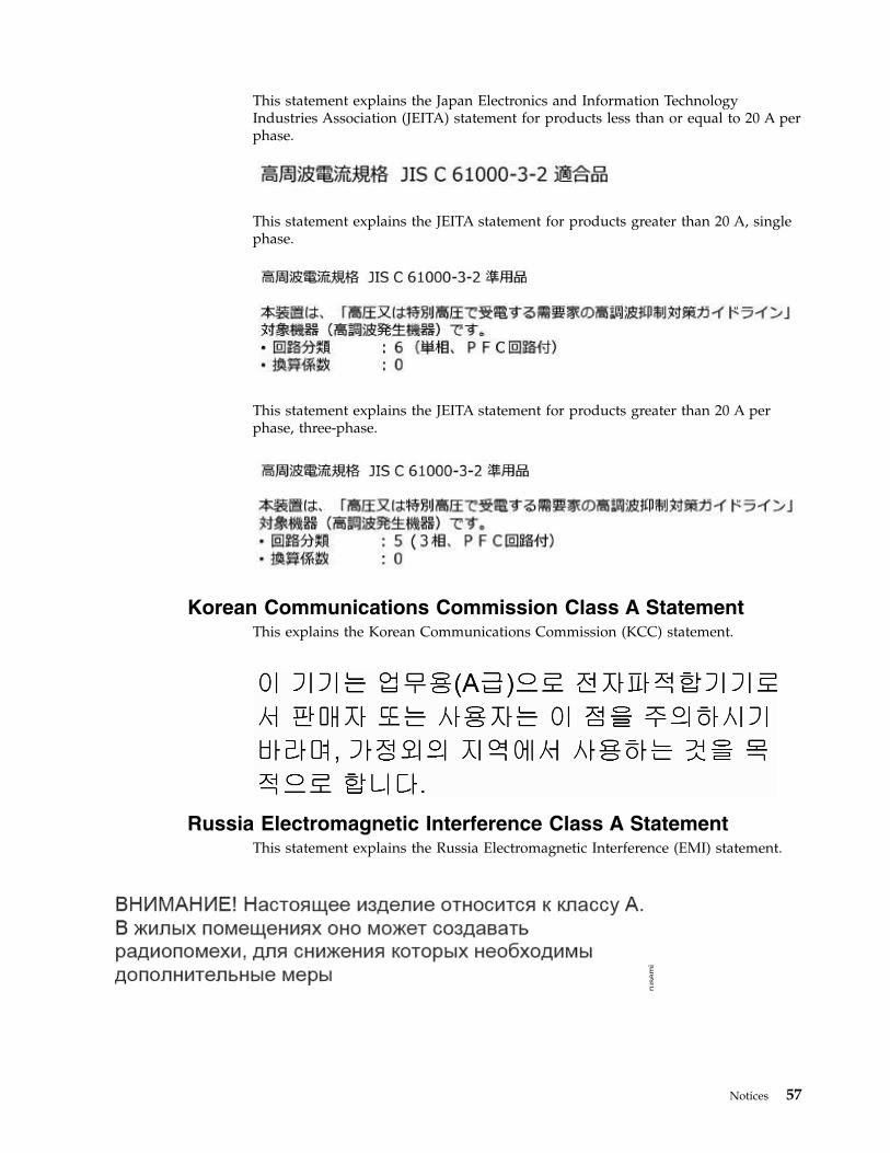
This statement explains the Japan Electronics and Information TechnologyIndustries Association (JEITA) statement for products less than or equal to 20 A perphase.
This statement explains the JEITA statement for products greater than 20 A, singlephase.
This statement explains the JEITA statement for products greater than 20 A perphase, three-phase.
Korean Communications Commission Class A StatementThis explains the Korean Communications Commission (KCC) statement.
Russia Electromagnetic Interference Class A StatementThis statement explains the Russia Electromagnetic Interference (EMI) statement.
rusem
i
Notices 57

58 Storwize V5000 Gen2: Quick Installation Guide

Index
Numerics1 Gbps iSCSI 4-port host interface card
Ethernet cables 3210 Gbps iSCSI-FCoE 4-port host interface
cardFibre Channel cables 33
Aaccessibility 47
repeat rateup and down buttons 47
accessingpublications 47
air flow 39
Bbrowsers
See web browsers
CCanadian electronic emission notice 54caution ixcaution notices xcomments xixconfiguration
web browserssettings 41
contact informationTaiwan 56
control enclosureadding to an existing system 46data ports 7installing 23location guidelines 16power cords 39rails 19
cooling 39
Ddanger ixdanger notices xiidc power supply units
connecting to power source 14replaceable units 15
DC power supply unitsconnectors 12LEDs 12
Deutschsprachiger EU Hinweis 54direct current power supply units
connecting to power source 14connectors 12LEDs 12replaceable units 15
disk driveslarge form factor 5
disk drives (continued)small form factor 5
Eelectronic emission notices
Deutschsprachiger EU Hinweis 54European Union (EU) 54Federal Communications Commission
(FCC) 53Germany 54Industry Canada 54Japanese Voluntary Control Council
for Interference (VCCI) 56Korean 57New Zealand 54People's Republic of China 55Taiwan 56
EMC statement, People's Republic ofChina 55
environmental notices ix, xvienvironmental requirements 16Ethernet
cablesfor 1 Gbps iSCSI 4-port host
interface cards 32for system management 30
ports 7switch 30, 32, 33
European Union (EU), EMC Directiveconformance statement 54
expansion canisterdata ports 9LEDs 39
expansion enclosureadding to an existing system 45attachment cables 24, 29installing 23location guidelines 16power cords 39rails 19
FFCC (Federal Communications
Commission) electronic emissionnotice 53
Federal Communications Commission(FCC) electronic emission notice 53
feedback xixFibre Channel
cables 35Fibre Channel 4-port host interface
card 35Fibre Channel cables 33
GGermany electronic emission compliance
statement 54
Hhardware components
identifying 7list 5
help xxhomologation statement 53host attachment cables 36host interface card
Fibre Channel 4-port 35
IIEC 60950-1 ixinformation help xxinitializing the system 43
JJapanese electronic emission notice 56
Kkeyboards
accessibility features 47Knowledge Center xviiKorean electronic emission statement 57
Llabels ixLEDs
expansion canister 39node canister 40
location guidelines 16
Mmanagement GUI
adding a control enclosure 46adding an expansion enclosure 45
Nnavigation
accessibility 47New Zealand electronic emission
statement 54node canister
Ethernet cables 30, 32Fibre Channel cables 33, 35LEDs 40
notices ixenvironmental ix, xvisafety ix
© Copyright IBM Corp. 2016 59

Ppacking slip 5password 43People's Republic of China, electronic
emission statement 55power cords 39powering on the system 39publications
accessing 47
Rrails 23
control enclosure 19expansion enclosure 19
reader feedback xixrelated information xvii
Ssafety ix
caution notices xdanger notices xiienvironmental notices ix
safety information labels ixsafety notices ixSAS cables 24, 29, 36send a comment xixshortcut keys
keyboard 47Statement of Limited Warranty, Where to
find the 49static-sensitive devices xvStorwize V5000
safety notices x, xiiStorwize V5000 library
related publications xviisuperuser 43
TTaiwan
contact information 56electronic emission notice 56
technical assistance xxtrademarks 53
Uuser name 43
Wweb browsers
configuring 41requirements 41
websites xix
60 Storwize V5000 Gen2: Quick Installation Guide


IBM®
Printed in USA
GC27-8581-00


![IBM Storwize V3500img.zhilankeji.com/ibm/storwize_v3500_01.pdf · 2013-12-18 · IBM Storwize V7000 2010 年 10 ... V7000 Storwize V7000 [ Unified ] DS4000, DS5000, Storwize V7000](https://img.dokumen.tips/doc/110x75/5f8da2e2ad21c4137b6552e2/ibm-storwize-2013-12-18-ibm-storwize-v7000-2010-10-v7000-storwize-v7000.jpg)