Embed Size (px)
Citation preview

Wireless TutorialWi-Fi, 3G, 4G, White Spaces and Beyond

Agenda10:30 – 12:00 noon Our G-enealogy – History and Evolution of
Mobile Radio Lunch
00 2 00 The IEEE’s Wireless Ethernet Keeps1:00 – 2:00 The IEEE’s Wireless Ethernet Keeps Going and Growing
2:00 – 2:45 4G Tutorial: Vive la Différence?Break
3:00 – 3:45 Mobile Broadband - New Applications and New Business ModelsNew Business ModelsBreak
4:00 – 4:45 Tutorial: White Spaces and Beyond
www.octoscope.com

OFDM OFDM →→OFDMAOFDMA
4G4G
MIMOMIMO
ugh
pu
t
ii iiWiMAXWiMAX
LTE3G3G
44
IEEE 802IEEE 802
city
/ t
hro
u
CDMA
WiWi--FiFi
UMTS/HSxPA2G2G
eles
s ca
pac
AMPS
GSMCDMA
Wir
e
First cell phones
www.octoscope.com
1970 1980 1990 2000 2010

Hi t f IEEE 802 11History of IEEE 802.111989: FCC authorizes ISM bands(Industrial, Scientific and Medical)
900 MHz, 2.4 GHz, 5 GHz
1990: IEEE begins work on 802.11g
1994: 2.4 GHz products begin shipping
1997: 802.11 standard approved1997: 802.11 standard approved
1998: FCC authorizes the UNII (Unlicensed National Information Infrastructure) Band - 5 GHz
20??: 802.11 ac/ad: 1 Gbps Wi-Fi
802 11 has pioneered 802 11 has pioneered Infrastructure) Band 5 GHz
1999: 802.11a, b ratified
2003: 802.11g ratified
2006 802 11n d aft 2 ce tification b
802.11 has pioneered 802.11 has pioneered commercial deployment of commercial deployment of OFDM and MIMO OFDM and MIMO –– key key wireless signaling wireless signaling
www.octoscope.com
2006: 802.11n draft 2 certification by the Wi-Fi Alliance begins
technologies todaytechnologies today

History of 802.161998: IEEE formed 802.16 WG
Started with 10–66 GHz band; later modified to work in 2–11GHz to enable NLOS (non-line of site)
2004: IEEE 802.16‐2004d Fixed operation standard ratified
2005: 802 16-2005e
From OFDM to OFDMAFrom OFDM to OFDMA
orthogonal frequency division multiplexingorthogonal frequency division multiple access
2005: 802.16-2005e Mobility and scalability in 2–6 GHz
Latest: P802.16Rev2/D8 draft
Future: 802.16m – next generationSDD (system definition document)SRD (system requirements document)
www.octoscope.com
( y q )

ITU T F kITU-T Framework
Pervasive connectivityPervasive connectivityWLAN WLAN -- WMAN WMAN -- WWANWWAN
IEEE 802.11IEEE 802.11 – WLAN (wireless local area network)
ITUITU--TT – United Nations telecommunications standards )
IEEE 802.16IEEE 802.16 – WMAN (wireless metropolitan area network)3GPP3GPP – WBA (wireless
organizationAccepts detailed standards
contributions from 3GPP, IEEE and other groups
www.octoscope.com
broadband access)and other groups

ITU International MobileITU International Mobile Telecommunications
IMT 2000IMT-2000Global standard for third generation (3G) wireless communicationsProvides a framework for worldwide wireless access by linking the diverse systems of terrestrial and satellite based networks. Data ate limit is app o imatel 30 MbpsData rate limit is approximately 30 Mbps Detailed specifications contributed by 3GPP, 3GPP2, ETSI and others
IMT-AdvancedNew generation framework for mobile communication systems beyondNew generation framework for mobile communication systems beyond IMT-2000 with deployment around 2010 to 2015 Data rates to reach around 100 Mbps for high mobility and 1 Gbps for nomadic networks (i.e. WLANs)IEEE 802 16m working to define the high mobility interfaceIEEE 802.16m working to define the high mobility interfaceIEEE 802.11ac and 802.11ad VHT (very high throughput) working to define the nomadic interface
www.octoscope.com

ITU Frequency Bands for IMT Advanced450-470 MHz450 470 MHz
698-960 MHz
1710 2025 MH
TDDTDD Time division duplex
1710-2025 MHz
2110-2200 MHzFDDFDD Frequency division duplex
(full and half duplex)
HH FDDFDD2300-2400 MHz
2500-2690 MHz FF--FDDFDD
HH--FDDFDD
500 690
3400-3600 MHz
www.octoscope.com

GSM, CDMA, UMTS…3GPP
802.15.3Bluetooth
PersonalPersonal
3GPPBluetooth60 GHzUWB
WideWide
802.22RegionalRegional
TVWS
RegionalRegional
802.16 WiMAX
802.11 Wi-Fi
LocalLocalMetroMetro
www.octoscope.com

02
IEEE 802 LAN/MAN Standards Committee (LMSC)
802.1 Higher Layer LAN Protocols
of I
EE
E 8
0
802.3 Ethernet802.11 Wireless LAN802.15 Wireless Personal Area Networkhe
wor
k of
802.15 Wireless Personal Area Network802.16 Broadband Wireless Access802.17 Resilient Packet Ring
omin
ate
th
802.18 Radio Regulatory TAG (technical advisory group)802.19 Coexistence TAG 802.21 Media Independent Handoffa
nd
ard
s d
o
802.21 Media Independent Handoff802.22 Wireless Regional Area Networks802 TV White Spaces Study Group
Wir
eles
s st
a
www.octoscope.com
W

IEEE 802 11 Active Task GroupsIEEE 802.11 Active Task Groups
TGn – High ThroughputTGp Wireless Access Vehicular Environment (WAVE/DSRC)TGp – Wireless Access Vehicular Environment (WAVE/DSRC)TGs – ESS Mesh NetworkingTGT – IEEE 802 PerformanceTGu – InterWorking with External NetworksTGv – Wireless Network ManagementTGw – Protected Management FramesgTGy – 3650-3700 MHz Operation in USATGz – Direct Link SetupTGaa – Robust streaming of AV Transport StreamsTGaa – Robust streaming of AV Transport StreamsTGac – VHTL6 (very high throughput < 6 GHz)TGad – VHT 60 GHz
www.octoscope.com
http://grouper.ieee.org/groups/802/11
Draft 802 11n vs Legacy ThroughputDraft 802.11n vs. Legacy Throughput Performance
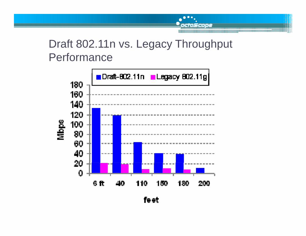
802 11n Throughput Enhancements802.11n Throughput Enhancements802.11n throughput enhancement Description
Throughput enhancement over legacyover legacy
Spatial multiplexing With 2 spatial streams throughput can be double that of a single stream. 100%
40 MHz channel Doubling the channel width over the 40 MHz channel width legacy 20 MHz channel can double the
throughput.100%
With 52 data sub-carriers vs. 48 for the legacy networks the highest data rateMore efficient OFDM legacy networks, the highest data rate per stream is 65 Mbps vs. the 802.11a/g 54 Mbps
20%
The short GI of 400 ns allowed by 802 11 d th b l ti fShorter GI 802.11n reduces the symbol time from 4 microseconds to 3.6 microseconds increasing the symbol rate by 10%.
10%
Frame aggregation 64k bytes A MPDU; 8k bytes A MSDU Up to 100%gg gand Block ACK 64k bytes A-MPDU; 8k bytes A-MSDU Up to 100%

IEEE 802 11a b g nIEEE 802.11a,b,g,n20 MHz Channel 40 MHz Channel
1 stream 2 streams 1 stream 2 streams
D t R t i MbData Rate, in Mbps802.11b 2.4 GHz 1, 2, 5.5, 11
802.11a 6, 9, 12, 18, 24, [1,] GI = Guard Interval, period within an OFDM 5 GHz 36, 48, 54
802.11g 2.4 GHz
1, 2, 6, 9, 12, 18, 24, 36, 48, 54
, psymbol allocated to letting the signal settle prior to transmitting the next symbol. Legacy 802.11a/b/g devices use 800ns GI. GI of 400ns is optional for 802.11n.
802.11nGI[1]=800ns 2.4 GHz
6.5, 13, 19.5, 26, 39, 52, 58.5, 65
13, 26, 39, 52, 78, 104, 117, 130
802.11n 6.5, 13, 19.5, 13, 26, 39, 52, 13.5, 27, 40.5, 27, 54, 81, 108, GI[1]=800ns 5 GHz
26, 39, 52, 58.5, 65
78, 104, 117, 130
54, 81, 108, 121.5, 135
162, 216, 243, 270
802.11n, GI=400ns 7.2, 14.4, 21.7, 28 9 43 3
14.4, 28.9, 43.3, 57.8, 15, 30, 45, 60,
90 120 13530, 60, 90, 120, 180 240 270
www.octoscope.com
2.4 and 5 GHz 28.9, 43.3, 57.8, 65, 72.2 86.7, 115.6,
130, 144.4
90, 120, 135, 150
180, 240, 270, 300

MIMO Radio SystemsMIMO Radio Systems2x3
Data is organized into spatial streams that are transmitted
TXTX RXRX
Data is organized into spatial streams that are transmitted simultaneously - This is known as Spatial MultiplexingSpatial Multiplexing
SISO: Single-Input/Single-Output; MIMO: Multi-Input/Multi-l / lOutput; SIMO: Single-Input/Multi-Output; MISO
There’s a propagation path between each transmit and receive antenna (a “MIMO path”)( p )
N x M MIMO ( e.g. “4x4”, “2x2”, “2x3”)N transmit antennasM i t
www.octoscope.com
M receive antennasTotal of N x M paths
15

Mobile reflector
clusters
Mobile device
MIMO transmission uses multipath to send twomultipath to send two or more streams
www.octoscope.com

I d MIMO M lti th Ch lIndoor MIMO Multipath Channel
Multipath reflections Moving reflectorReflector
come in “clusters”
Reflections in a cluster i t i ll
o g e ec o
Rx
arrive at a receiver all from the same general direction Wall
Direct ray
Statistics of clusters are key to MIMO system
tiReflector
Txoperation
802.11n developed 6 models: A through F
Tx
www.octoscope.com
models: A through F
17

Example 2x2 MIMO Channel ModelExample 2x2 MIMO Channel Model
H12
H21
Time-varying FIR filter weightsSpatially correlated: H11 correlated with H12, etc., according to antenna spacing and cluster statistics
www.octoscope.com
spacing and cluster statisticsTime correlated according to the Doppler model

MIMO Channel Emulation
U d tDSP
4 x 4 MIMO paths to support 802.11nWiMAX eq i es 2 2
Up-down converters
WiMAX requires 2 x 2802.11n and ITU M.1225 channel models Bidirectionality required to support beamforming
www.octoscope.com
Bidirectionality required to support beamforming

M i i l M lti th E i tMunicipal Multipath Environment
www.octoscope.com

Outdoor Multipath EnvironmentOutdoor Multipath Environment
Base Station(BS)
i ll di picocell radius: r < 100 mmicro: 100 m < r < 1 000 mmacro: r > 1 000 m
One or two dominant paths in outdoor environments – fewer paths and less scattering than indoors
www.octoscope.com
scattering than indoors

802 11 Ch l M d l802.11n Channel ModelsParameters A B C D E F
ModelsParameters A B C D E FAvg 1st Wall Distance (m) 5 5 5 10 20 30RMS Delay Spread (ns) 0 15 30 50 100 150Maximum Delay (ns) 0 80 200 390 730 1050Number of Taps 1 9 14 18 18 18
Delay spread is a function of the size of the modeled environment
Number of Taps 1 9 14 18 18 18Number of Clusters N/A 2 2 3 4 6
Delay spread is a function of the size of the modeled environment
Number of clusters represents number of independent propagation paths modeled
Doppler spectrum assumes reflectors moving in environment at 1.2 km/h, which corresponds to about 6 Hz in 5 GHz band, 3 Hz in 2.4 GHz band
www.octoscope.com

ITU MIMO Channel Models – For BWA
WiMAX system performance simulations are based on ITU models
Channel Model Path 1 Path 2 Path 3 Path 4 Path 5 Path 6
ITU Pedestrian B( l ti fi )
0 dB0
-0.9 dB200
-4.9 dB800
-8.0 dB1200
-7.8 dB2300
-23.9 dB3700
y p f
(relative figures) 0 ns 200 ns 800 ns 1200 ns 2300 ns 3700 nsITU Vehicular A(relative figures)
0 dB0 ns
-1.0 dB310 ns
-9.0 dB710 ns
-10.0 dB1090 ns
-15.0 dB1730 ns
-20.0 dB2510 ns
Channel Model Speed Probability
ITU Pedestrian B 3 km/hr 60%ITU V hi l A 30 k /h 30%ITU Vehicular A 30 km/hr 30%
120 km/hr 10%
www.octoscope.com
BWA = Broadband Wireless Access

Li htl R l t d B d f 802 11 802 16Lightly Regulated Band for 802.11, 802.16
March 2005 FCC offered 50 MH 3650 t 3700 300 Million licenses50 MHz 3650 to 3700 MHz for contention-based protocol
300 Million licensesone for every person or company
802.11y meets FCC requirement; 802.16h is working to comply
$300 per license for 10 years
Registered stations (base stations): 1 W/MHz ~15 km
21st century regulation geared for digital communications
stations): 1 W/MHz, ~15 km
Unregistered stations(handsets, laptops): 40
multiple services to share the band in an orderly way
mW/MHz, 1-1.5 km
www.octoscope.com

IEEE 802 11 TimelineIEEE 802.11 TimelineTGk
TGma TGn TG TGn
TGp TGr
TGs TGT
TGa TGb TGb-cor1
TGc TGd TGe
Part of 802.1
withdrawnTGu
TGv TGw TGy
TGF TGg
TGh TGi
TGj
withdrawn
1997 1998 1999 2000 2001 2002 2003 2004 2005 2006 2007 2008 2009 2010
TGj
8
802.11-1999 IEEE Standard April 1999 802.11-2007
IEEE StandardJune 2007
www.octoscope.com
802.11-1997 IEEE Standard July 1997

Making 802.11 Enterprise-grade802.11r
Fast Roaming
√ l d√ released
802.11kRadio Resource Measurement
√ released
802.11vWireless Network Management
www.octoscope.com

802 11 F t T iti (R i )802.11r Fast Transition (Roaming)Needed by voice applicationsBasic methodology involves propagating authentication information for connected stations through the ‘mobility domain’ to eliminate the need for re-authentication upon station transition from one APstation transition from one AP to anotherThe station preparing the roam
t th t t AP tcan setup the target AP to minimize the actual transition time
www.octoscope.com

802.11k Radio Resource Measurement
I t f 802 11k f th E t i th tImpetus for 802.11k came from the Enterprises that needed to manage their WLANs from a central point
802.11k makes a centralized network management802.11k makes a centralized network management system by providing layer 2 mechanisms for
Discovering network topologyMonitoring WLAN devices, their receive power levels, PHYMonitoring WLAN devices, their receive power levels, PHY configuration and network activity
Can be used to assists 802.11r Fast Transition (roaming) protocol with handoff decisions based on the loading ofprotocol with handoff decisions based on the loading of the infrastructure, but 802.11v is more focused on load balancing
www.octoscope.com

802.11v Wireless Network Management TGv’s charter is to build on the network measurement mechanisms defined by TGk andmeasurement mechanisms defined by TGk and introduce network management functions to provide Enterprises with centralized network management and load balancing capabilities.
Major goals: manageability, improved power efficiency and interference avoidanceD fi t l f ti d tiDefines a protocol for requesting and reporting location capability
Location information may be CIVIC (street address) or GEO (longitude, latitude coordinates)
For the handset, TGv may enable awareness of AP e911 capabilities while the handset is in sleep mode; this work has common ground with TGu
www.octoscope.com
with TGu

802.11v Improves Power EfficiencyTGv defines FBMS (flexible broadcast multicast service) - the mechanism to letmulticast service) the mechanism to let devices extend their sleep period Devices can specifying the wake up interval to be longer than a single DTIMinterval to be longer than a single DTIM (delivery traffic indication message). This consolidates traffic receive/transmit intervals and extends battery life ofintervals and extends battery life of handsets.
www.octoscope.com

Making Wi-Fi Carrier-grade?802.11u - InterWorking with External NetworksNetworks
Main goal is to enable Interworking with external networks, including other 802 based networks such as 802.16 and 802.3 and 3GPP based IMS networksM k di llManage network discovery, emergency call support (e911), roaming, location and availabilityThe network discovery capabilities give a station looking to connect information aboutstation looking to connect information about networks in range, service providers, subscription status with service providers
802.11u makes 802.11 networks more lik ll l t k h hlike cellular networks where such information is provided by the infrastructure
www.octoscope.com

802 11p Wireless Access Vehicular802.11p Wireless Access Vehicular Environment (WAVE)
Transportation communications systems under development byTransportation communications systems under development by Department of Transportation (DoT)
802.11p is the PHY in the Intelligent Transportation Systems (ITS)
WAVE is also called DSRC (Dedicated Short Range Communications)
WAVE/DSRC is the method for vehicle /to vehicle and vehicle to road-side unit communications to support…
Public safetyCollision avoidanceCollision avoidanceTraffic awareness and managementTraveler informationToll booth payments
www.octoscope.com

802 11p Wireless Access Vehicular Environment (WAVE)802.11p Wireless Access Vehicular Environment (WAVE)
Operates in the p5.9 GHz frequency band dedicated by the dedicated by the FCC for WAVE/DSRC
This band falls right above the 802 11a band 802.11a band, making it supportable by h i lthe commercial
802.11a chipsets

Wireless MeshWireless MeshWired connection to each AP 802.11s802.11s
802.16j (relay)802.16j (relay)802.16m (built802.16m (built--in meshing)in meshing)802.15.5802.15.5BWA backhaul meshBWA backhaul mesh
Traditional WLAN
Mesh Portal
WLAN
Wired links
Mesh Mesh links
Cli t li k
www.octoscope.com
Client links

IEEE 802 11 M hIEEE 802.11s Mesh
Wireless Distribution System withMP (Mesh P i t)Wireless Distribution System with
automatic topology learning and wireless path configurationSelf-forming self-healing
Point)
Self forming, self healing, dynamic routing~32 nodes to make routing algorithms computationallyalgorithms computationally manageableExtension of 802.11i security and 802 11e QoS protocol to operate Mesh Portal802.11e QoS protocol to operate in a distributed rather than centralized topology
Mesh Portal
www.octoscope.com

802 11s Mesh Enhanced Stations802.11s Mesh Enhanced StationsMultiple association capability reduces hops capability reduces hops between server and client stations
www.octoscope.com

Fast Handoff in Dynamic MeshesFast Handoff in Dynamic MeshesTo support VoIP, 802.11s needs to incorporate the fast handoff mechanisms defined in 802.11r.
Enable stations to roam from one mesh AP to another withinEnable stations to roam from one mesh AP to another within approximately 50 ms without noticeable degradation in the quality of a voice call In a dynamic mesh (e.g. in vehicles) MPs may be roaming with
t t th MP d th 802 11 t d d i f trespect to other MPs and the 802.11s standard requires fast roaming of MPs with respect to one another.
www.octoscope.com

802 11 S it802.11s Security802.11s has to make special provisions for security. In the traditional fixed infrastructure stations authenticate through APstraditional fixed infrastructure stations authenticate through APs with a centralized AAA server.
In a mesh network MPs have to mutually authenticate with one another. 802.11s security features extend 802.11i to peer-to-peeranother. 802.11s security features extend 802.11i to peer to peer environment.
www.octoscope.com

IEEE 802 16 d 802 15 M h St d dIEEE 802.16 and 802.15 Mesh Standards802.16j and 802.15.5
l t d di iare also standardizing mesh topologies
802 16j is not an ad-hocWireless relay802.16j is not an ad-hoc
mesh, but a relay to extend the range b d
relay
between a CPE and a base station
802 16m has meshing802.16m has meshing protocol built in
www.octoscope.com

C ll l Mi B kh l M hCellular Microwave Backhaul MeshMicrowave
hub
Fiber MSC
hub
Microwave
Fiber access
capacity
Microwave backhaul for base stations can be configured in PTP, PTMP, mesh, and ring topologies.
NGMN* (www.ngmn.org) and 3GPP are considering the mesh architecture due to its high resiliency and redundancy.
www.octoscope.com40
* NGMN is an organization of major operators that defines high level requirements for 3GPP.

IEEE 802.16 Active Task Groups
802 16h Li E t T k G802.16h, License-Exempt Task Group Working with 802.11 TGy and 802.19 Coexistence TAG
802.16j, Mobile Multihop Relay80 6j, ob e u t op e ayExtended reach between BS (base station) and CPE (customer premises equipment)
802 16m IMT Advanced Air Interface802.16m, IMT Advanced Air Interface
MaintenanceDeveloping 802.16Rev2Working with the WiMAX Forum
http://grouper.ieee.org/groups/802/16
www.octoscope.com

WiMAX ForumWiMAX ForumIEEE 802.16 contains too many options
The WiMAX Forum defines certification profiles on parts of the standard p pselected for deployment; promotes interoperability of products through testing and certification
The WiMAX Forum works closely with the IEEE 802.16 Maintenance ygroup to refine the standard as the industry learns from certification testing
Release 1.0 802.16e/TDD
Release 1.5 802.16e/TDD and FDD
Release 2 0 802 16m (IMT Advanced)
current
Under development
Future
www.octoscope.com
Release 2.0 802.16m (IMT Advanced)Future

Mobility and HandoffTwo basic requirements forTwo basic requirements for mobility
Location management: tracking where a mobile station (MS) is at any timeHandoff management:Handoff management: ensuring a seamless transition for the current session as the MS t f thMS moves out of the coverage range of one base station and into the range of another
www.octoscope.com

Location ManagementThe MS periodically informs the network of its current location: location registration
Location area usually includes one or more base stationsbase stations
Needs to be done frequently to ensure accurate information is recorded about the location of each MSlocation of each MS
When an incoming call arrives at the network, the paging process is initiated
The recipient's current location is retrieved from a database and the base stations in that area page the subscriber
www.octoscope.com
p g

Handoff WiMAX requires handoff latency be q yless than 50ms with an associated packet loss of less than 1 percent for speeds up to 120kmphspeeds up to 120kmph
The MS makes the decisions while the BS makes recommendations onthe BS makes recommendations on target BS’s for the handoff
Either the SINR (Signal to Interference plus Noise Ratio) or RSS (receive signal strength) can be used as criteria
www.octoscope.com
as criteria

V i R i tVoice RequirementsPacket loss, especially bursty packet loss, causes poor signal qualityqualityDelay and jitter (variation in delay) can also cause loss of quality200 ms events (signal loss or delay) are audible to the ear( g y)In wireless networks, bursty packet loss can be due to
Congestion in the infrastructureClient roaming from one AP to another
~20-30 millisecond gaps
~100 microsecondpackets, depending on CO C
www.octoscope.com
CODEC

Video RequirementsVideo RequirementsFormat Average throughput
required for high quality q g q yvideo480i60 1080p30
BroadcastCable TV
MPEG-2 8 Mbps 20 Mbps
Windows Media VideoDi X
MPEG-4 Part 2
5 Mbps 12 Mbps
DivXXviDQuickTime

Vid S illVideo SurveillanceRequired qthroughput is a function of video frame rate frame rate, resolution and colorApproximately
Mb d d f 2 Mbps needed for full VGA, 7 frames/sec/

802 Wireless802 11802.11
Faster (802.11n, ac/ad)More power efficient (sleep modes 802.11n, u, v)L ti (802 11 )Location aware (802.11u, v)VoIP and Video capableManageable
802.16Scalable, supports mobility 802.16m has built in meshing and femtocell support
White spaces Major new disruptive market Currently no industry standard other than FCC
www.octoscope.com
Currently no industry standard other than FCC

Agenda10:30 – 12:00 noon Our G-enealogy – History and Evolution of
Mobile Radio Lunch
00 2 00 The IEEE’s Wireless Ethernet Keeps Going1:00 – 2:00 The IEEE’s Wireless Ethernet Keeps Going and Growing
2:00 – 2:45 4G Tutorial: Vive la Différence?Break
3:00 – 3:45 Mobile Broadband - New Applications and New Business ModelsNew Business ModelsBreak
4:00 – 4:45 Tutorial: White Spaces and Beyond
www.octoscope.com

4G Starts in the Home
xDSL, CableMetro EthernetMetro Ethernet
Broadband IP access
www.octoscope.com
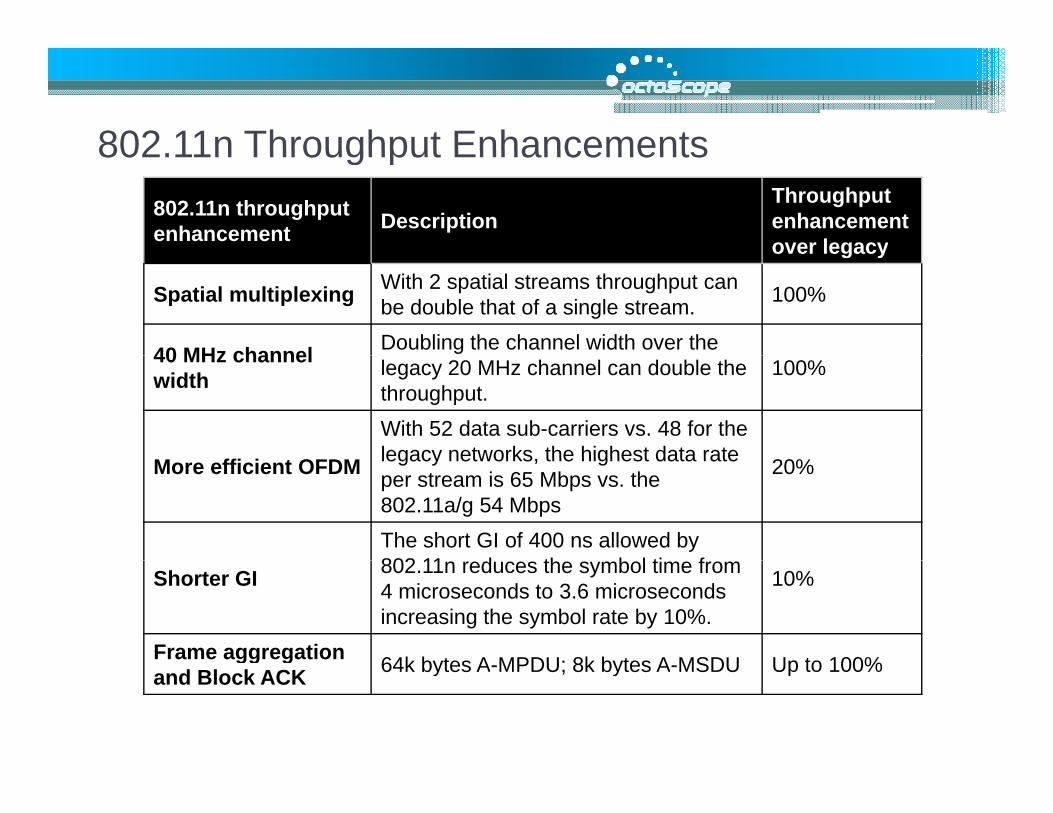
hp
ut Cell size
shrinks as throughput
hro
ug
h throughput and usage increase
Th
# subscribers, throughput
www.octoscope.com

Ethernet
Femtocell
xDSL, CableMetro Ethernet
B db d
Wi-Fi
Home AP/router
Broadband IP access
Femtocells allow the use of ordinary cell phones over b db dbroadband IP access
Wi-Fi enabled cell phones can work via Wi-Fi APs
www.octoscope.com
work via Wi Fi APs

Orange and T-Mobile have launched GAN/UMA services
Sprint has launched Femtocell
Wi Fi cell phone transitions
Sprint has launched Femtocell service, at&t and Verizon have made Femtocell announcements
Wi-Fi cell phone transitions between cellular and Wi-Fi networks (3GPP GAN, VCC or proprietary SIP)
Femtocells support traditional phones
www.octoscope.com
traditional phones
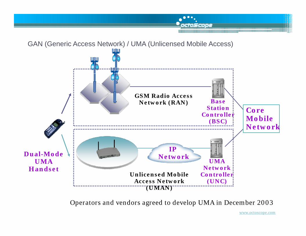
GAN (Generic Access Network) / UMA (Unlicensed Mobile Access)GAN (Generic Access Network) / UMA (Unlicensed Mobile Access)
BaseGSM Radio Access
Network (RAN) BaseStation
Controller(BSC)
Network (RAN)CoreMobileNetwork
Dual-ModeUMA
IP Network
UMAUMAHandset
UMANetwork
Controller(UNC)
Unlicensed Mobile Access Network
(UMAN)
www.octoscope.com
Operators and vendors agreed to develop UMA in December 2003

Data Networks vs. Traditional Cellular Networks
VLR
BSC
HLRPSTN
MSC 2
VLR
BSC
GMSC*
MSC 2
IP NetworkVLR
BSCMSC 1CellularNetwork
BSC
Today’s cellular infrastructure is Today s cellular infrastructure is set up for thousands of BSCs, not millions of femtocells.
www.octoscope.com
*Gateway Mobile Switching Center

Traditional “Stovepipe” IMS
V i I t t
ng/
OSS
ence
ng/
OSS
ence
Billing/OSSBilling/OSS
QoSQoS
Voice Internet Video …Voice Internet
… IMS
Bil
lin
QoS
Pre
se
Bil
lin
QoS
Pre
seIP NetworkIP Network
PresencePresence… IMS
Network
TraditionalCellularNetwork
M bilM bil FixedMobile FixedMobile
Stovepipe model – replicates functionality
IMS – common layers facilitate adding services
www.octoscope.com
g

Key Components of the IMS ArchitectureKey Components of the IMS Architecture
CSCF (call session control function)
Heart of IMS architecture ApplicationsHandles multiple real-time IP based services (voice, IMM, streaming video, etc.)Responsible for registering user devices and for ensuring QoS
Applications Applications Servers (AS)Servers (AS)
HSS (home subscriber server)
Central repository for customer dataInterfaces with operators HLRs
CSCFCSCFHSSHSSControl
Interfaces with operators HLRs (home location registers), which keep subscriber profilesEnables roaming across distinct access networks
MediaMediagatewaygatewayTransport
AS (application server)Delivers services, such as gaming, video telephony, etc.Types of AS: SIP, Parlay X, customized legacy AS
IP t k t
www.octoscope.com
IP network, gateways to legacy networks

LTE A hit t IMS B dLTE Architecture – IMS BasedLTE specifies IP multimedia subsystem (IMS), optimizing the architecture for servicesfor services .
IMS is being used in wired infrastructure to enable VoIP and other applications; LTE expands on this capability to deliver seamless services.
Hotspot-like initial deployments, primarily in urban areas will leverageHSPA for full coverage
Most LTE devices will be multi-mode, supporting HSPA and other interfaces
LTE femtocells will be integrated in the architecture from the onset to increase capacity and indoor coverage.
www.octoscope.com

3GPP (3rd Generation Partnership Project)
60
3GPP (3 d Generation Partnership Project)
Japan
USA
Partnership of 6 regional standards groups, which translate 3GPP specifications to regional standardsITU references the regional standards
www.octoscope.com
g

Operator Influence on LTE
61
Operator Influence on LTELTE was built around the features and capabilities defined by Next Generation M bil N t k (NGMN) AlliMobile Networks (NGMN) Alliance (www.ngmn.org)
Operator buy-in from ground-up formed 9/2006 by major LTE/SAE (Service Architecture Evolution)
Trial Initiative (LSTI) formed through the cooperation of vendors and operators to b i t ti LTE l i th d l t
by major operators:
Sprint NextelChina Mobile
begin testing LTE early in the development process (www.lstiforum.org)
NGMN defines the requirements
bVodafoneOrange T-Mobile KPN M bil
q
LSTI conducts testing to ensure conformance.
KPN Mobile NTT DoCoMo
www.octoscope.com

LTE Frequency Bands - FDDBand Uplink (UL) Downlink (DL)
1 1920 -1980 MHz 2110 - 2170 MHz 2 1850 1910 MHz 1930 1990 MHz
LTE Frequency Bands FDD
2 1850 -1910 MHz 1930 - 1990 MHz3 1710 -1785 MHz 1805 -1880 MHz4 1710 -1755 MHz 2110 - 2155 MHz5 824 849 MHz 869 894 MHz5 824-849 MHz 869 - 894 MHz6 830 - 840 MHz 875 - 885 MHz7 2500 - 2570 MHz 2620 - 2690 MHz8 880 915 MHz 925 960 MHz8 880 - 915 MHz 925 - 960 MHz9 1749.9 - 1784.9 MHz 1844.9 - 1879.9 MHz
10 1710 -1770 MHz 2110 - 2170 MHz11 1427 9 - 1452 9 MHz 1475 9 - 1500 9 MHz11 1427.9 1452.9 MHz 1475.9 1500.9 MHz12 698 - 716 MHz 728 - 746 MHz13 777 - 787 MHz 746 - 756 MHz14 788 - 798 MHz 758 - 768 MHz
www.octoscope.com
14 788 798 MHz 758 768 MHz17 704 - 716 MHz 734 - 746 MHz
Source: 3GPP TS 36.104 V8.4.0 (2008-12)

LTE F B d TDDLTE Frequency Bands - TDDBand Uplink (UL) /Downlink (DL)Band Uplink (UL) /Downlink (DL)
33 1900 - 1920 MHz34 2010 - 2025 MHz35 1850 - 1910 MHz 36 1930 - 1990 MHz 37 1910 - 1930 MHz 38 2570 - 2620 MHz 39 1880 - 1920 MHz 40 2300 2400 MHz40 2300 – 2400 MHz
Source: 3GPP TS 36.104 V8.4.0 (2008-12)
www.octoscope.com

LTE and WiMAXLTE and WiMAX Modulation and Access
CDMA (code division multiple access) is a coding and accessCDMA (code division multiple access) is a coding and access scheme
CDMA, W-CDMA, CDMA-2000
SDMA ( di i i lti l ) i hSDMA (space division multiple access) is an access schemeMIMO, beamforming, sectorized antennas
TDMA (time division multiple access) is an access schemeAMPS, GSM
FDMA (frequency division multiple access) is an access scheme
( h l f d l l ) d lOFDM (orthogonal frequency division multiplexing) is a modulation scheme
OFDMA (orthogonal frequency division multiple access) is a
www.octoscope.com
( g q y p )modulation and access scheme
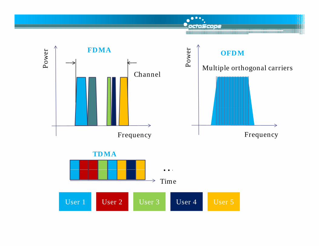
FDMA
Pow
er OFDM
Multiple orthogonal carriersPow
er
ChannelChannel
FrequencyFrequency
…TDMA
q y
…Time
U 1 U 2 U 3 U 4 U 5User 1 User 2 User 3 User 4 User 5

FDMA vs OFDMAFDMA vs. OFDMAOFDMA is more frequency efficient th FDMAthan FDMA
Each station is assigned a set of subcarriers, eliminating frequency guard bands between usersbands between users
ChannelGuard band
www.octoscope.com
FDMAFDMA OFDMAOFDMA

Pow
er Fixed OFDMA
Tim
e Dynamic OFDMA
P T
Frequency Frequency
Frequency allocation per i i i
Frequency allocation per user is d namicall user is continuous vs. time user is dynamically allocated vs. time slots
U 1 U 2 U 3 U 4 U 5User 1 User 2 User 3 User 4 User 5

Key Features of WiMAX and LTEKey Features of WiMAX and LTEOFDMA (Orthogonal Frequency Division Multiple Access)
Users are allocated a slice in time and frequencyUsers are allocated a slice in time and frequency
Flexible, dynamic per user resource allocation
Base station scheduler for uplink and downlink resource allocationResource allocation information conveyed on a frame‐by frame basisResource allocation information conveyed on a frame‐by frame basis
Support for TDD (time division duplex) and FDD (frequency division duplex)
DLUL
TDD: single frequency channel for uplink and downlink
DL
ULFDDPaired channels
www.octoscope.com
UL Paired channels

OFDMA b l b TimeOFDMA symbol number Time
chan
nel
Subc
y
TDD T i i
Fre
quen
cy
TDD Transmission

TimeTime
equ
ency
Fre
H FDD (h lf d l FDD) T i iH-FDD (half-duplex FDD) Transmission

SDMA S t A t T h l iSDMA = Smart Antenna TechnologiesBeamforming
Use multiple-antennas to spatially shapeUse multiple-antennas to spatially shape the beam to improve coverage and capacity
Spatial Multiplexing (SM) or C ll b ti MIMOCollaborative MIMO
Multiple streams are transmitted over multiple antennasMulti-antenna receivers separate the t t hi hi h th h tstreams to achieve higher throughput
In uplink single-antenna stations can transmit simultaneously
Space-Time Code (STC)2x2 Collaborative MIMO increases the
k d f ld Space Time Code (STC)Transmit diversity such as Alamouti code [1,2] reduces fading
peak data rate two-fold by transmitting two data streams.
www.octoscope.com

ScalabilityScalabilityWiMAX
Channel bandwidth (MH )
1.25 5 10 20 3.5 7 8.75(MHz)
Sample time (ns) 714.3 178.6 89.3 44.6 250 125 100
FFT size 128 512 1024 2048 512 1024 1024
Sampling factor (ch bw/sampling freq)
28/25 8/7
Subcarrier spacing 10.9375 7.8125 9.766(kHz)
Symbol time (usec) 91.4 128 102.4
LTELTE
Channel bandwidth (MHz)
1.4 3 5 10 15 20
www.octoscope.com
FFT size 128 258 512 1024 1536 2048

3G/4G Comparison3G/4G ComparisonPeak Data Rate (Mbps) Access time
(msec)D li k U li kDownlink Uplink
HSPA (today) 14 Mbps 2 Mbps 50-250 msec
HSPA (R l 7) MIMO 2 2 28 Mb 11 6 Mb 50 250 HSPA (Release 7) MIMO 2x2 28 Mbps 11.6 Mbps 50-250 msec
HSPA + (MIMO, 64QAMDownlink)
42 Mbps 11.6 Mbps 50-250 msec
WiMAX R l TDD ( Mb Mb WiMAX Release 1.0 TDD (2:1 UL/DL ratio), 10 MHz channel
40 Mbps 10 Mbps 40 msec
LTE (Release 8), 5+5 MHz channel
43.2 Mbps 21.6 Mbps 30 msecchannel
Release 8 – LTERelease 9 – enhancements to LTE, 2009
www.octoscope.com
Release 9 enhancements to LTE, 2009Release 10 - LTE Advanced (1Gbps DL and 500 Mbps UL, 100 MHz bw) 2010
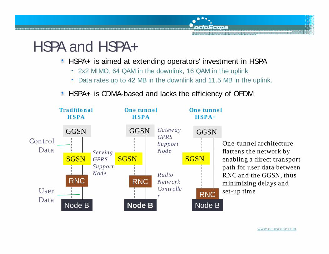
HSPA and HSPA+HSPA and HSPA+HSPA+ is aimed at extending operators’ investment in HSPA
2x2 MIMO, 64 QAM in the downlink, 16 QAM in the uplink Data rates up to 42 MB in the downlink and 11 5 MB in the uplinkData rates up to 42 MB in the downlink and 11.5 MB in the uplink.
HSPA+ is CDMA-based and lacks the efficiency of OFDM
Traditional One tunnel One tunnel
One tunnel architecture
Gateway GPRS Support Control
Traditional HSPA
One tunnel HSPA
One tunnel HSPA+
GGSN GGSN GGSN
One-tunnel architecture flattens the network by enabling a direct transport path for user data between RNC and the GGSN thus
ServingGPRS Support Node
Support Node
Radio
Control Data
SGSNSGSNSGSN
RNC and the GGSN, thus minimizing delays and set-up time
Node Radio Network Controller
User Data
Node B Node BRNC
Node B
RNCRNC
www.octoscope.com
Node B Node B Node B

LTE SAE (System Architecture Evolution)LTE SAE (System Architecture Evolution)
GPRS CoreSGSNHSS
MME PCRF
Trusted
SAE, PDN gateways IP Services
(IMS)
i i
(IMS)SGSN (Serving GPRS Support Node)
PCRF (policy and charging enforcement function) Non-
Trusted
eNode-B Trusted non-3GPP IP Access (CDMA, TD-SCDMA, WiMAX)
Wi-Fi)
HSS (Home Subscriber Server)
MME (Mobility Management Entity)
3GPP
Non-Trusted
www.octoscope.com
SAE (System Architecture Evolution)
PDN (Public Data Network)
SAE includes RAN and EPS

EPS (Evolved Packet System)EPS (Evolved Packet System)EPS is the core network for LTE and other advanced RAN technologies
Flat IP architecture minimizes round trip time (RTT) to <10N tN tSAE GWPDN GWFlat IP architecture minimizes round trip time (RTT) to <10
ms and setup time to <100 msHigher data rates, seamless interworking between 3GPP and non-3GPP networks and IMSPrimary elements are eNodeB, MME (Mobility Management
Not Not hierarchical hierarchical
as GSMas GSMEDGEEDGEHSPAHSPA
PDN GW
Entity) and the SAE gateway
MME provides connectivity between the eNodeB and the legacy GSM and UMTS networks via SGSN*. The MME also supports the following: user equipment context and identity, authorization, and
HSPAHSPA
MMEg q p y, ,
authentication.
The SAE gateway, or EPS access gateway, provides the PDN (packet data network) gateway and serving gateway functions.
eNode-BSGSN
www.octoscope.com
*GPRS Gateway Support NodeServing GPRS Support Node

BackhaulBackhaulLTE requires high-capacity links between eNodeB and the core. The options are:
Backhaul is the key to reducing TCO for operators.
options are: Existing fiber deployments Microwave in locations where fiber is unavailableEthernet
Co-location of LTE with legacy networks means the backhaul has to support
GSM/UMTS/HSPA/LTE or LTE/CDMA Time division multiplexing (TDM), asynchronous transfer mode (ATM) and Ethernet traffic
Non-TDM backhaul solutions may be unable t i t i th t i t Ethernet traffic
NGMN wants to standardize backhaul in order to reduce cost while meeting stringent synchronization requirements.
to maintain the strict timing required for cellular backhaul.
www.octoscope.com
stringent synchronization requirements.

Multi-Protocol Label Switching (MPLS) BackhaulMulti-Protocol Label Switching (MPLS) Backhaul
WiMAXWiMAX
GbEGbE
WiMAXWiMAX
b d d f b kh l
GbEGbE
HSPAHSPA
MPLS is being considered for backhaulingSupports TDM, ATM, and Ethernet simultaneouslyIncorporates RSVP-TE (Resource Reservation Protocol Traffic Engineering) for end to end QoS
eNodeeNode--BB
Protocol-Traffic Engineering) for end-to-end QoS Enables RAN sharing via the use of VPNs
BS (base stations) could act as edge MPLS
www.octoscope.com
routers, facilitating migration to pure IP.

WiMAX s LTEWiMAX vs. LTE
C li iCommonalitiesIP-basedOFDMA and MIMOSimilar data rates and channel widths
DifferencesDifferencesCarriers are able to set requirements for LTE through organizations like NGMN and LSTI, but cannot do this as easily at the IEEE based 802 16the IEEE based 802.16LTE backhaul is designed to support legacy services while WiMAX is better suited to greenfield deployments
www.octoscope.com

Commercial IssuesLTE WiMAX
Deployments likely slower than projected
WiMAX2-3 year lead, likely maintained for yearsp j
ButEventual migration
yDedicated spectrum in many countriesEventual migration
path for GSM/3GSM, i.e. for > 80% share
But Likely < 15% share by
& th Will be lowest cost & dominant in 2020
2020 & thus more costly
www.octoscope.com

Agenda10:30 – 12:00 noon Our G-enealogy – History and Evolution of
Mobile Radio Lunch
00 2 00 The IEEE’s Wireless Ethernet Keeps Going1:00 – 2:00 The IEEE’s Wireless Ethernet Keeps Going and Growing
2:00 – 2:45 4G Tutorial: Vive la Différence?Break
3:00 – 3:45 Mobile Broadband - New Applications and New Business ModelsNew Business ModelsBreak
4:00 – 4:45 Tutorial: White Spaces and Beyond
www.octoscope.com
p y

TV S t A il bilitTV Spectrum Availability6 MHz TV channels 2-69
VHF: 54 72 76 88 174 216VHF: 54-72, 76-88, 174-216 MHzUHF: 470-806 MHz
2009 t iti f l t2009 transition from analog to digital TV frees up channels 52-69 due to higher spectral efficiency of digital TVefficiency of digital TV
FCC is updating its regulations and has recently allowed the
f d f huse of cognitive radio for White Spaces, unused TV spectrum
WSD = white spaces device
www.octoscope.com
p

White Space Channel AvailabilityWhite Space Channel Availability
Approximate White Space UHF channel availability based on
Available Channels:1 or none
channel availability based on full-service post-transition broadcast station allocation
3 or fewer10 or fewer20 or more
duTreil, Lundin & Rackley, Inc. Sarasota, Florida
30 or more

h S R d h lWhite Spaces Radio TechnologyThe new regulations (FCC Dockets 04-186, g ( ,02-380) require the use of cognitive radios to determine whether a channel is available prior to transmitting.
Two types of services are targeting TV spectrum:
Fixed services: WRAN (wireless rural area networks) being standardized by IEEE802 22networks), being standardized by IEEE802.22 Mobile services: White Spaces, being advocated by the WIA (www.wirelessinnovationalliance.org) IEEE 802 LAN/MAN committee formed new study group in November, 2008 to investigate white spaces standardization
www.octoscope.com

Detecting Licensed TransmissionsDetecting Licensed TransmissionsMethods for detecting licensed transmissions:
An internal GPS could be used in conjunction with a databaseAn internal GPS could be used in conjunction with a database to determine whether the WSD is located far enough away from licensed stations. WSD could receive information from a broadcast station indicating which channels are available.
Protected devices:
WSD could incorporate sensing capabilities to detect whether licensed transmitters are in its range. If no signals are detected, the device could transmit. If signals are detected, the device would have to search for another channel.
devices: TV stations, wireless microphones
FCC sensing thresholds : -116 dBm for ATSC (Advanced Television Systems Committee, digital TV)-94 dBm for NTSC (National Television System Committee,94 dBm for NTSC (National Television System Committee, analog TV) -107 dBm for wireless microphones
www.octoscope.com

Hidden Node ScenarioHidden Node Scenario
TV i l tt t d b TV signal attenuated by an obstruction (wall) is undetectable by a WSD. WSD transmits, interfering with TV broadcast, which is received unobstructed by a rooftop antenna.
TV broadcast received by an unobstructed
rooftop TV antenna
www.octoscope.com
rooftop TV antenna
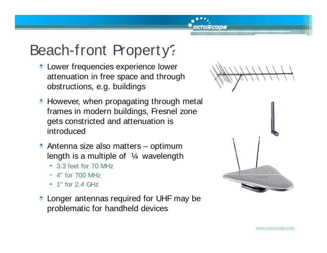
B h f t P t ?Beach-front Property?Lower frequencies experience lower attenuation in free space and throughattenuation in free space and through obstructions, e.g. buildings
However, when propagating through metal frames in modern buildings Fresnel zoneframes in modern buildings, Fresnel zone gets constricted and attenuation is introduced
lAntenna size also matters – optimum length is a multiple of ¼ wavelength
3.3 feet for 70 MHz4” for 700 MHz4 for 700 MHz1” for 2.4 GHz
Longer antennas required for UHF may be bl ti f h dh ld d i
www.octoscope.com
problematic for handheld devices

Antenna Fresnel ZoneAntenna Fresnel Zone
r
r = radius in feetD = distance in milesf f i
D
Fresnel zone is the shape of electromagnetic signal and is a function of frequency
Constricting the Fresnel zone introduces attenuation and signal distortion
f = frequency in GHz
Example: D = 0.5 mileExample: D 0.5 miler = 30 feet for 700 MHzr = 16 feet for 2.4 GHzr = 10 feet for 5.8 GHz
www.octoscope.com

Hidden Node – an Issue?
fAnalysis and field testing done by ITU-R, FCC and other organizations demonstrate that even when a WSD is deep inside a building the signalwhen a WSD is deep inside a building, the signal reaching it is likely to be at most 30 dB lower than the signal at a rooftop antenna.than the signal at a rooftop antenna.
The 802.22 draft sets the detection threshold 30 dB below a tuner’s lowest receive level anddB below a tuner s lowest receive level and states that an unlicensed device must detect a broadcast within 2 seconds and with probability
www.octoscope.com
of >=90%.

Turf Battles to Continue…Broadcasters and traditionalBroadcasters and traditional wireless operators will continue to oppose TV White Spaces developments
The battle lines are drawn and the stakes are high
www.octoscope.com

AdditionalAdditionalContentContent
www.octoscope.com

ITU T Voice Quality StandardsITU-T Voice Quality Standards• MOS (mean opinion score) uses
a wide range of human subjects to provide a subjective quality score (ITU-T P.800)
• PESQ (perceptual speech quality measure) sends a voice quality measure) sends a voice pattern across a network and then compares received pattern to the original pattern and computes the quality rating (ITU-T P.862)
• R-Factor (Rating factor) computed based on delay packet loss and other network performance and other network performance parameters; R-Factor directly translates into MOS (ITU-T G.107)
www.octoscope.com

ITU T PESQ M d lITU-T PESQ Model

ITU-T E-Model (G.107) for Computing R-Factor ( ) p g
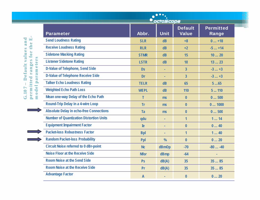
Parameter Abbr. UnitDefault Value
Permitted Range -
Send Loudness Rating SLR dB +8 0 … +18Receive Loudness Rating RLR dB +2 -5 … +14Sidetone Masking Rating STMR dB 15 10 … 20Listener Sidetone Rating LSTR dB 18 13 23 v
alu
es
an
de
s fo
r th
e E
-e
rs Listener Sidetone Rating LSTR dB 18 13 … 23D-Value of Telephone, Send Side Ds - 3 -3 … +3D-Value of Telephone Receive Side Dr - 3 -3 … +3Talker Echo Loudness Rating TELR dB 65 5 …65
7 –
De
fau
lt
mit
ted
ra
ng
ee
l p
ara
me
te
Weighted Echo Path Loss WEPL dB 110 5 ... 110Mean one-way Delay of the Echo Path T ms 0 0 … 500Round-Trip Delay in a 4-wire Loop Tr ms 0 0 … 1000Absolute Delay in echo-free Connections Ta ms 0 0 … 500
G.1
07
pe
rmm
od
e
y Ta ms 0 0 … 500Number of Quantization Distortion Units qdu - 1 1 … 14Equipment Impairment Factor Ie - 0 0 … 40Packet-loss Robustness Factor Bpl - 1 1 … 40R d P k t l P b bilitRandom Packet-loss Probability Ppl % 0 0 … 20Circuit Noise referred to 0 dBr-point Nc dBmOp -70 -80 … -40Noise Floor at the Receive Side Nfor dBmp -64 -Room Noise at the Send Side Ps dB(A) 35 35 … 85( )Room Noise at the Receive Side Pr dB(A) 35 35 … 85Advantage Factor A - 0 0 … 20
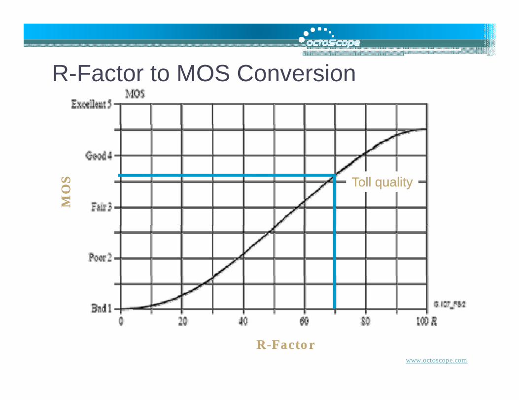
R Factor to MOS ConversionR-Factor to MOS Conversion
Toll qualityToll quality
MO
SM
OS
www.octoscope.com
RR--FactorFactor

Video MetricsVideo MetricsMedia Delivery Index (MDI) defined in RFC 4445 describes media capacity of a network composed of the Media Loss pRate (MLR) and Delay Factor (DF)
MLR is a media-weighted metric that expresses the number of expected IEEE Std 802.11 packets dropped from a
dvideo streamDF represents the amount of time required to drain the endstation buffer at the bit rate of the media stream
MLR = (Packets Expected - Packets Received) / Interval in Seconds
DF is calculated as follows:VB = |Bytes Received - Bytes Drained|DF = (max(VB) – min(VB)) / Video Bit rate in BytesWhere VB = video buffer
www.octoscope.com


![WiFivLight [Mode de compatibilité]matlesiouxx.free.fr/Cours/Fiifo5/Advanced Networks/WiFivLight.pdf · WLAN WMAN WRAN • IEEE 802.15.1-Bluetooth • IEEE 802.15.3 -UWB ... – Envoi](https://img.dokumen.tips/doc/110x75/5b9e50cd09d3f204248b884c/wifivlight-mode-de-compatibilite-networkswifivlightpdf-wlan-wman-wran-.jpg)