Embed Size (px)
Citation preview

Juan Antonio Infantes Diaz
WIRELESS SENSOR NETWORKSCONTROLLED WITH PIC
MICROCONTROLLERS ANDZIGBEE PROTOCOL
Bachelor’s Thesis Information Technology
May 2012

2
Contents
1 INTRODUCTION 6
1.1 Report organization . . . . . . . . . . . . . . . . . . . . . . . . . . . 7
2 PROBLEM DESCRIPTION 8
2.1 X-10 . . . . . . . . . . . . . . . . . . . . . . . . . . . . . . . . . . . 8
2.1.1 X-10 Problems . . . . . . . . . . . . . . . . . . . . . . . . . 9
2.2 Wire network, KNX . . . . . . . . . . . . . . . . . . . . . . . . . . 11
3 SOLUTION 12
3.1 Objectives . . . . . . . . . . . . . . . . . . . . . . . . . . . . . . . . 12
3.2 Planning . . . . . . . . . . . . . . . . . . . . . . . . . . . . . . . . . 13
4 TECHNOLOGY USED 14
4.1 Zigbee . . . . . . . . . . . . . . . . . . . . . . . . . . . . . . . . . . 14
4.1.1 Zigbee topologies . . . . . . . . . . . . . . . . . . . . . . . . 14
4.1.2 Comparing Zigbee . . . . . . . . . . . . . . . . . . . . . . . 16
4.1.3 Security . . . . . . . . . . . . . . . . . . . . . . . . . . . . . 17
4.2 Microcontrollers . . . . . . . . . . . . . . . . . . . . . . . . . . . . . 18
4.2.1 Arduino . . . . . . . . . . . . . . . . . . . . . . . . . . . . . 18
4.2.2 Pinguino . . . . . . . . . . . . . . . . . . . . . . . . . . . . . 20
4.2.3 Arduino vs Pinguino . . . . . . . . . . . . . . . . . . . . . . 22
4.2.4 Zigbee Shield for Pinguino . . . . . . . . . . . . . . . . . . . 23
4.3 Relay shield . . . . . . . . . . . . . . . . . . . . . . . . . . . . . . . 24
4.4 Interface controller board . . . . . . . . . . . . . . . . . . . . . . . . 25
4.5 Mister House . . . . . . . . . . . . . . . . . . . . . . . . . . . . . . 28
5 PROJECT DEVELOPMENT 29
5.1 Architecture . . . . . . . . . . . . . . . . . . . . . . . . . . . . . . . 29
5.2 Module diagram . . . . . . . . . . . . . . . . . . . . . . . . . . . . . 32
5.2.1 Debug . . . . . . . . . . . . . . . . . . . . . . . . . . . . . . 33
5.2.2 Hardware . . . . . . . . . . . . . . . . . . . . . . . . . . . . 33
3
5.2.3 USB . . . . . . . . . . . . . . . . . . . . . . . . . . . . . . . 34
5.2.4 Zigbee . . . . . . . . . . . . . . . . . . . . . . . . . . . . . . 35
5.2.5 Utils . . . . . . . . . . . . . . . . . . . . . . . . . . . . . . . 38
5.2.6 Protocol . . . . . . . . . . . . . . . . . . . . . . . . . . . . . 38
5.2.7 Control . . . . . . . . . . . . . . . . . . . . . . . . . . . . . 40
5.3 Protocols . . . . . . . . . . . . . . . . . . . . . . . . . . . . . . . . 41
5.3.1 Slave protocol . . . . . . . . . . . . . . . . . . . . . . . . . . 41
5.3.2 USB master protocol . . . . . . . . . . . . . . . . . . . . . . 43
5.3.3 Zigbee master protocol . . . . . . . . . . . . . . . . . . . . . 44
5.3.4 Executing action from Web Interface . . . . . . . . . . . . . 46
5.4 Network autodiscovering . . . . . . . . . . . . . . . . . . . . . . . . 47
5.5 Drivers . . . . . . . . . . . . . . . . . . . . . . . . . . . . . . . . . . 48
5.6 Mister House library . . . . . . . . . . . . . . . . . . . . . . . . . . 49
6 CONCLUSIONS 49
6.1 Licence . . . . . . . . . . . . . . . . . . . . . . . . . . . . . . . . . . 50
6.2 Future work . . . . . . . . . . . . . . . . . . . . . . . . . . . . . . . 50
7 Bibliography 52
4
List of Figures
1.1 Home automation example. Source [17] . . . . . . . . . . . . . . . . 6
2.1 PL513. Source [16]. . . . . . . . . . . . . . . . . . . . . . . . . . . . 9
2.2 X-10 filter . . . . . . . . . . . . . . . . . . . . . . . . . . . . . . . . 10
4.1 Zigbee star topology. Source [15]. . . . . . . . . . . . . . . . . . . . 15
4.2 Zigbee tree topology. Source [10]. . . . . . . . . . . . . . . . . . . . 16
4.3 Zigbee mesh topology. Source [15]. . . . . . . . . . . . . . . . . . . 17
4.4 Arduino Uno. Source [13]. . . . . . . . . . . . . . . . . . . . . . . . 19
4.5 Arduino Ethernet. Source [13]. . . . . . . . . . . . . . . . . . . . . . 19
4.6 Arduino Bluetooth. Source [13]. . . . . . . . . . . . . . . . . . . . . 20
4.7 Arduino Nano. Source [13]. . . . . . . . . . . . . . . . . . . . . . . 20
4.8 Arduino Mega. Source [13]. . . . . . . . . . . . . . . . . . . . . . . 21
4.9 Pinguino 8 bits. Source [5] . . . . . . . . . . . . . . . . . . . . . . . 21
4.10 Pinguino 32 bits. Source [5] . . . . . . . . . . . . . . . . . . . . . . 22
4.11 Zigbee Shield. Source [8] . . . . . . . . . . . . . . . . . . . . . . . . 23
4.12 Zigbee Shield connected to Pinguino. Source [5] . . . . . . . . . . . 24
4.13 Relay shield . . . . . . . . . . . . . . . . . . . . . . . . . . . . . . . 24
4.14 Interface controller shield . . . . . . . . . . . . . . . . . . . . . . . . 26
4.15 Interface and relay shield connections . . . . . . . . . . . . . . . . . 27
4.16 Mister House logo. Source [6]. . . . . . . . . . . . . . . . . . . . . 28
4.17 Mister House web interface 1 . . . . . . . . . . . . . . . . . . . . . . 29
5.1 Architecture diagram . . . . . . . . . . . . . . . . . . . . . . . . . . 29
5.2 Low level module diagram . . . . . . . . . . . . . . . . . . . . . . . 32
5.3 High level module diagram . . . . . . . . . . . . . . . . . . . . . . . 37
5.4 Protocol scenario for executing action in the device . . . . . . . . . 41
5.5 Protocol scenario for connection successful. . . . . . . . . . . . . . . 42
5.6 Protocol scenario for retransmitting a packet. . . . . . . . . . . . . 43
5.7 Protocol scenario of executing an action coming from USB. . . . . . 44
5.8 Protocol scenario for retrieving connected slaves. . . . . . . . . . . . 44
5.9 Protocol scenario of re-transmitting information to slaves. . . . . . . 45
5.10 Protocol scenario of new slave connection. . . . . . . . . . . . . . . 46
5
5.11 Protocol scenario of ACK. . . . . . . . . . . . . . . . . . . . . . . . 46
5.12 Protocol scenario of executing action in the master device. . . . . . 47
5.13 Protocol scenario of re-transmitting information. . . . . . . . . . . . 47
5.14 Executing action from Web Interface. . . . . . . . . . . . . . . . . . 48
6.1 Visits in the Blog . . . . . . . . . . . . . . . . . . . . . . . . . . . . 50

6
1. INTRODUCTION
Home automation is currently a new growing field in Computer Science: The goal
of this automation is controlling the house elements (lights, heating, air condi-
tioner, ...) in order to save energy and raise the quality of living of the house
inhabitants.
In the figure 4.10 we can see one example house using home automation:
Figure 1.1: Home automation example. Source [17]
One of the main problems applying this new technology is that it is needed to wire
some elements inside of the rooms and between rooms, and this can arise some
difficulties with old buildings. A wireless communication between elements and
rooms would settle effectively the problem.

7
Analyzing the actual market in home automation we found that X-10 [1] (which
is a Power Line Carrier protocol) is the most used option; although, X-10 devices
are expensive and there are not solid neither standards solutions for all scenes.
1.1. Report organization
• Chapter 1: Introduction to the project and report organization.
• Chapter 2: It describes the home automation implementation problem.
• Chapter 3: The solution that came up in with this final thesis.
• Chapter 4: It introduces the technology that has been used to develop and
carry out the project.
• Chapter 5: Programming specifications, protocols, UML diagrams in order
to understand how the project has been developed.
• Chapter 6: Conclusions and future work that can be done in this field.
• Chapter 7: Bibliography
8
2. PROBLEM DESCRIPTION
2.1. X-10
When we think about installing our house with home automation and we go to the
market to see what are the technologies that are being used, we found the X-10
protocol as an Home Automation standard protocol. Although this is a propri-
etary protocol, it showed up in 1975 and this made that lot of houses nowadays
use this system, actually, more than 8 millions of houses use X-10 protocol.
X-10 is a Power Line Carrier protocol, that means that it uses the power line
for the frames transmissions, it is flexible and there are a lot of devices that can
”speak” X-10. Most of the devices are plug and play, so the installation is not
really complicated.
There are 4 kind of X-10 devices:
• Transmitters: they only send orders trough the power line. One transmitters
can transmit up to 256 devices at ones and multiples transmitters can send
instruction to the same device.
• Receivers: they can only received information and for example if they are
computers, they can report the status of the home network through a we-
b/desktop interface.
• Transceivers: They can send and receive information from other devices.
• Wireless devices: They use a normal transceiver attached to the power line
and then this transceiver sends the information wireless to other wireless
device. These devices use 433 Mhz in Europe and 310 Mhz in US and they
are not working with medium/long distances, its normal range is 5-10m.
X-10 works at 120 Khz and sends the information just after the zero crossing point
of the electric wave.
9
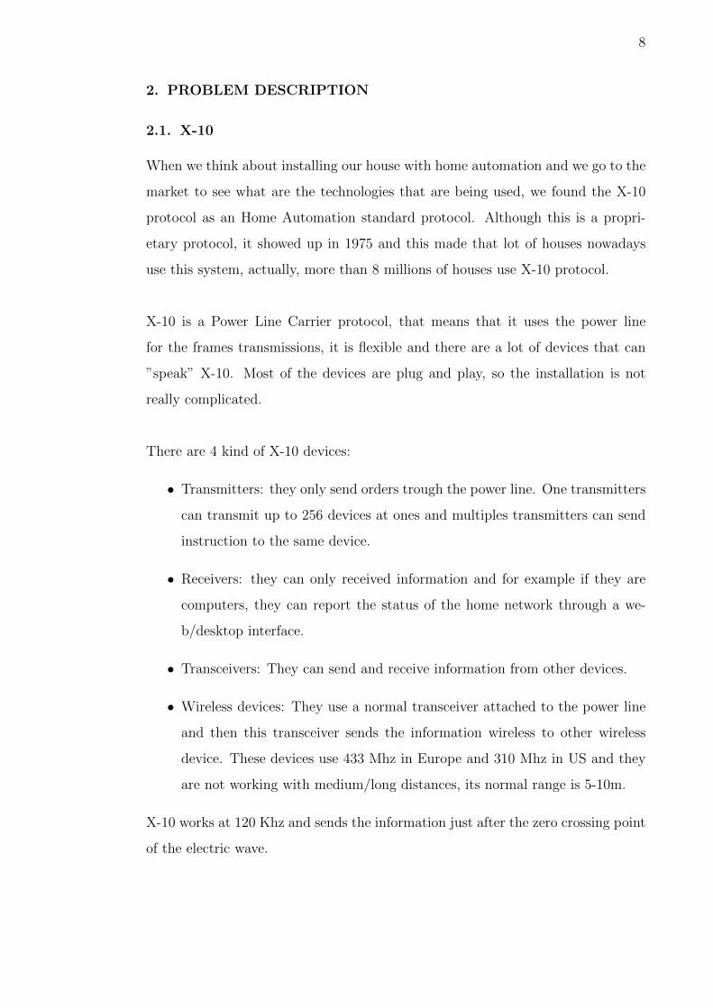
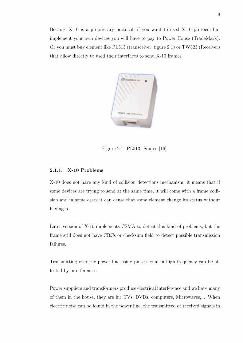
Because X-10 is a proprietary protocol, if you want to used X-10 protocol but
implement your own devices you will have to pay to Power House (TradeMark).
Or you must buy element like PL513 (transceiver, figure 2.1) or TW523 (Receiver)
that allow directly to used their interfaces to send X-10 frames.
Figure 2.1: PL513. Source [16].
2.1.1. X-10 Problems
X-10 does not have any kind of collision detections mechanism, it means that if
some devices are trying to send at the same time, it will come with a frame colli-
sion and in some cases it can cause that some element change its status without
having to.
Later version of X-10 implements CSMA to detect this kind of problems, but the
frame still does not have CRCs or checksum field to detect possible transmission
failures.
Transmitting over the power line using pulse signal in high frequency can be af-
fected by interferences.
Power suppliers and transformers produce electrical interference and we have many
of them in the house, they are in: TVs, DVDs, computers, Microwaves,... When
electric noise can be found in the power line, the transmitted or received signals in
10
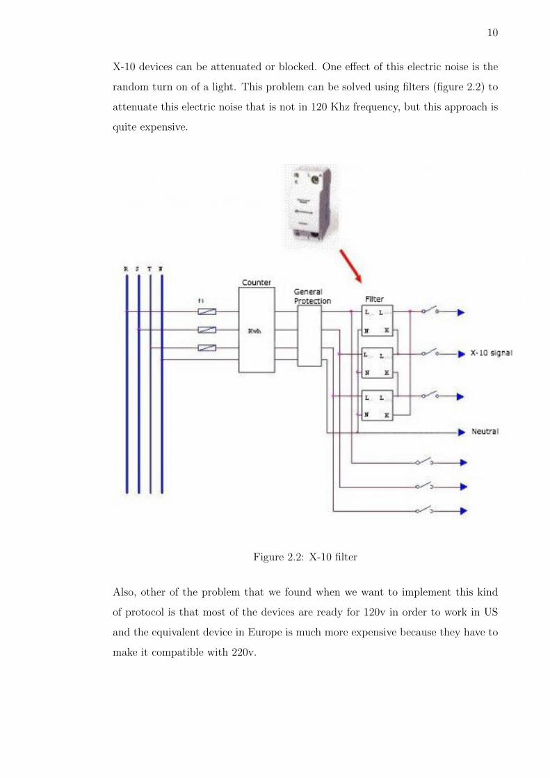
X-10 devices can be attenuated or blocked. One effect of this electric noise is the
random turn on of a light. This problem can be solved using filters (figure 2.2) to
attenuate this electric noise that is not in 120 Khz frequency, but this approach is
quite expensive.
Figure 2.2: X-10 filter
Also, other of the problem that we found when we want to implement this kind
of protocol is that most of the devices are ready for 120v in order to work in US
and the equivalent device in Europe is much more expensive because they have to
make it compatible with 220v.
11
2.2. Wire network, KNX
As we have already seen X-10 is not a good idea for a home automation system
in Europe. So, if we want to look for another solution we will have to wire our
house in order to interconnect the devices that will control our system. Looking
to this approach we find KNX, it is a standard based on network communications
protocol for intelligent buildings. It has severals implementations:
• Twisted pair wiring
• Power line networking, similar to X-10.
• Radio, KNX-RF
• Ethernet
If we implement the power line networking we will find the same problem with the
attenuation thanks to the other devices that we have in the house, and if we used
twisted pair wiring which seems to be the most trusted one, we will have to add
a wire between all the home automation devices that we will install. Sometimes
it is also really complicated, if not impossible without modifying the building
infrastructure, to wire all the devices.
12
3. SOLUTION
3.1. Objectives
Due to the problems that we find if we try to use the power line for transmitting
the information to the devices that are controlling the house elements (like lights,
microwave) and the problem that we find if we try to wire a old building, the best
alternative is using a wireless communication.
During the research part of this final thesis, we decide to use Zigbee wireless pro-
tocol to be the communication layer of our home automation system. More details
about Zigbee will be found in the Technology chapter.
Ones we have decided the communications, we need to decide which hardware
can ”talk” with this wireless protocol, after a comparative research, we find that
Microchip company has very cheap and clever solution for Zigbee and that they
have also microcontrollers that have an easy integration with this kind of commu-
nication protocol.
With all the infrastructure ready to send and receive instructions/orders, we
would like to make a Home Automation system that can be easily installed, Open
Source/Hardware, and completely functional for most of the house.
Summarizing:
The objective of this final thesis is developing a Wireless Auto-organized network
library for Microchip microcontrollers using Zigbee technology for Home Automa-
tion. This system will be joined to Mister House Home Automation software.
When the project will be finished we will be able to install Pinguino 32 bits devices
in the points of the house that we want to control (for example lights) and later,
using a Web Interface we will be able for example to turn on or off those lights.
13
3.2. Planning
This will be the secuence of goals that will be developed during the project life.
1. Study the Pinguino 32 bit microcontroller platform.
2. State of the art of the low power consumption networks based of Zigbee.
3. Study the auto-organized networks protocols.
4. Make the library and the protocol for connecting a PC with Pinguino using
USB (CDC).
5. Make the library that gives to Pinguino the possibility to create auto-organized
networks.
6. Integrate the library with Mister House in order to close the loop of the
Home automation system.
In the step 4 we will be able to send instructions from a PC (using terminal) to
the Pinguino.
In the step 5 we will be able to send instructions from a PC (using terminal) to
the Pinguino Master and it will resend the instruction to all the other Pinguino
Slaves that are forming the network.
In the step 6 we will change the PC terminal for a web interface through that we
will be able to control any Pinguino in our network.
14
4. TECHNOLOGY USED
4.1. Zigbee
Zigbee [2] is a high level wireless protocols set of low power consumption based in
the 802.15.4 IEEE standard. It tries to be the perfect protocol for low bandwidth,
low send rate and secure communications. Zigbee is an alliance of more than 100
companies like LG, Philips, Samsung,... and its goal is helping deploying low price
wireless network.
Zigbee covers the Physical Layer and Data Link Layer, the upper layers should be
implemented by the developers if they need it. It implements solutions for star,
mesh, and tree topologies.
All Zigbee networks need a coordinator (that should be the central one) and its
mission is routing and helping in routing. The coordinator has different names
depending on the topology of the network.
Zigbee, also known as HomeRF lite, is a technology with range of speed from 20
Kb/s to 250 Kb/s and distance range from 10m to 2km. It uses a free wireless
band, 2,4 Ghz, 868 Mhz (in Europe) and 915 Mhz (in US).
A Zigbee network can be composed of 255 nodes and most of the time this
transceivers will be sleeping, looking for saving power. The protocol specifica-
tion wants a transceiver to be on with two AA batteries at least 6 months and up
to 2 years.
4.1.1. Zigbee topologies
• Star topology: there are two kind of devices, the central node and the rest
of nodes. All the nodes are connected to the central node and all the com-
munication flows through it. We can see an example of this kind of network
in the figure 4.1.

15
This kind of network represents a risky scenario and the problem is that if
the central node goes down, the network will stop working. Also if someone
is able to replace the central node with a malicious one, it will be able to
read all the data from the network.
Talking about our topic, home automation, it is not a good idea to use this
kind of network. If the central node goes down (that for example is control-
ling the kitchen), we won’t be able to control the rest of the house.
Implementing this network topology means that all the devices can reach
always the central node, and if we are installing zigbee devices in all rooms
it is quite possible that not all of them have connection to the central node.
Figure 4.1: Zigbee star topology. Source [15].
• Tree topology: this topology has a main node called top node and below it
there are branches which connect the different nodes. When a node wants to
send a packet to another node, the packet will go up until the root node that
connects both end nodes. We can see an example of this kind of network in
the figure 4.2.
This approach could be a good idea if we want to connect devices inside of

16
a room to a room master device and then this room master device to the
main house device. But it has the same problem that the star topology, if
the central node fails, some areas of the houses are going to be in troubles.
Figure 4.2: Zigbee tree topology. Source [10].
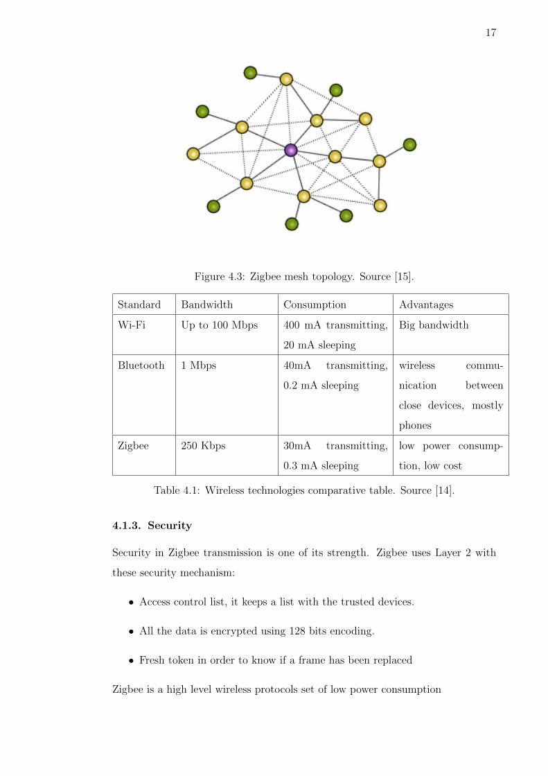
• Mesh topology: this is the more flexible topology that we can implement
using Zigbee technology. In this kind of network all the devices can commu-
nicate with each others.
The network will find the route automatically to deliver the message correctly
and the main advantage of this kind of network is that they are decentral-
ized, if some node has problems, it doesn’t mean that the whole network will
go down like it happens when we use the above topologies.
4.1.2. Comparing Zigbee
Comparing wireless technology, we can find the table 4.1.
It is expected that Zigbee transceivers will be the cheapest wireless transceivers
in the market with a cost around 2 e. They have an integrated antenna and
frequency control.
17
Figure 4.3: Zigbee mesh topology. Source [15].
Standard Bandwidth Consumption Advantages
Wi-Fi Up to 100 Mbps 400 mA transmitting,
20 mA sleeping
Big bandwidth
Bluetooth 1 Mbps 40mA transmitting,
0.2 mA sleeping
wireless commu-
nication between
close devices, mostly
phones
Zigbee 250 Kbps 30mA transmitting,
0.3 mA sleeping
low power consump-
tion, low cost
Table 4.1: Wireless technologies comparative table. Source [14].
4.1.3. Security
Security in Zigbee transmission is one of its strength. Zigbee uses Layer 2 with
these security mechanism:
• Access control list, it keeps a list with the trusted devices.
• All the data is encrypted using 128 bits encoding.
• Fresh token in order to know if a frame has been replaced
Zigbee is a high level wireless protocols set of low power consumption
18
4.2. Microcontrollers
The microcontroller is going to be the brain of the Home Automation system that
we are going to build and some of the things that we should look for in those small
processors is the flexibility that they will give to the system.
We have a limited time to develop the project so we will try to find the easiest and
cheapest solution in order to satisfy the needs of the system, looking to that we will
try to find a hardware that can be highly compatible with Zigbee communication.
They should have low power consumption and have enough I/O input to control
some elements inside of a room at least.
One of the most important features that we would like to add to the system is that,
it should be completly Open Hardware/Software, so we need a microcontroller that
can be programmed using Open Source Software. Filtering these criteria we will
compare Arduino and Pinguino.
4.2.1. Arduino
Arduino is an open platform based on Open Source and Open Hardware. It consists
of an Atmel microcontroller board and an IDE written in Java. It has a big
community developing libraries and sketch code what makes it a very confident
platform for new hardware developer.
There are several Arduino models depending on the features of the project that
you want to develop. The most interesting one are:
• Arduino Uno: It is the standard Arduino. It uses 8 bit microcontroller,
ATmega328. It has 32 Kb flash memory, 2 Kb RAM, 16 Mhz, 1 Serial port,
6 analog I/O ports, 13 digital ports.
• Arduino Ethernet: It has the same functionality than the normal one but
also includes Ethernet connectivity.
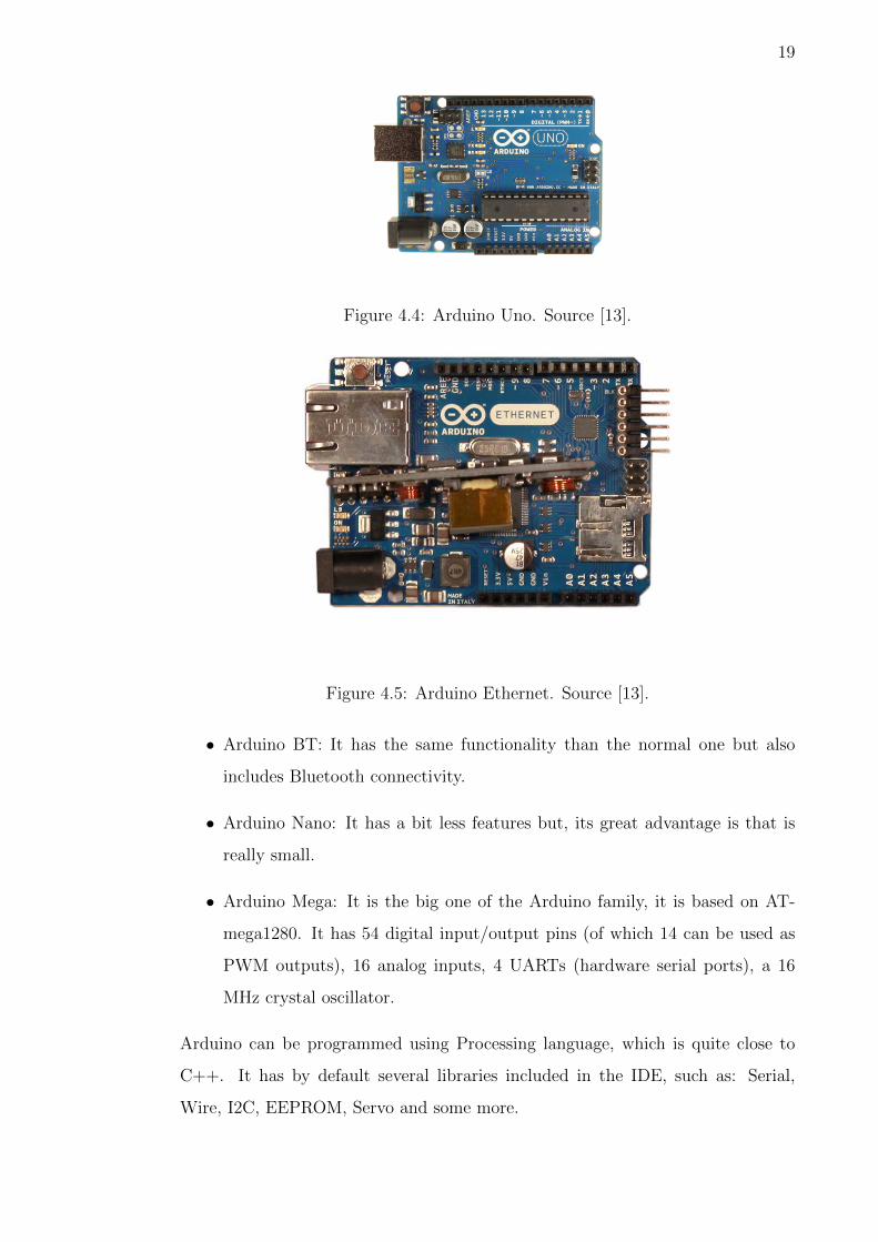
19
Figure 4.4: Arduino Uno. Source [13].
Figure 4.5: Arduino Ethernet. Source [13].
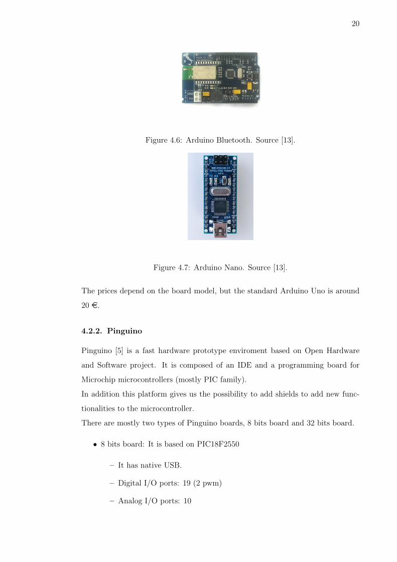
• Arduino BT: It has the same functionality than the normal one but also
includes Bluetooth connectivity.
• Arduino Nano: It has a bit less features but, its great advantage is that is
really small.
• Arduino Mega: It is the big one of the Arduino family, it is based on AT-
mega1280. It has 54 digital input/output pins (of which 14 can be used as
PWM outputs), 16 analog inputs, 4 UARTs (hardware serial ports), a 16
MHz crystal oscillator.
Arduino can be programmed using Processing language, which is quite close to
C++. It has by default several libraries included in the IDE, such as: Serial,
Wire, I2C, EEPROM, Servo and some more.
20
Figure 4.6: Arduino Bluetooth. Source [13].
Figure 4.7: Arduino Nano. Source [13].
The prices depend on the board model, but the standard Arduino Uno is around
20 e.
4.2.2. Pinguino
Pinguino [5] is a fast hardware prototype enviroment based on Open Hardware
and Software project. It is composed of an IDE and a programming board for
Microchip microcontrollers (mostly PIC family).
In addition this platform gives us the possibility to add shields to add new func-
tionalities to the microcontroller.
There are mostly two types of Pinguino boards, 8 bits board and 32 bits board.
• 8 bits board: It is based on PIC18F2550
– It has native USB.
– Digital I/O ports: 19 (2 pwm)
– Analog I/O ports: 10

21
Figure 4.8: Arduino Mega. Source [13].
– Flash memory: 32 Kb
– SRAM: 2 Kb
– EEPROM: 256 Bytes
– Clock rate: 20 Mhz
– The price is around: 13 e
Figure 4.9: Pinguino 8 bits. Source [5]
• 32 bits board: It is based on the 32 bit Microchip microcontroller PIC32MX440F256H.
– It runs at 80 Mhz
– It has OTG (which allow Pinguino to communicate with OTG compat-
ible devices like Android devices).
– It has microSD card for data logging.
– DCDC power supply allow power supply voltage from 9 to 30V DC
thus making possible to take virtually any power supply adapter on the

22
market, also enable application which are in industrial power supply
24VDC.
– Li-Ion rechargable battery power supply option with BUILT-IN on
board charger, so when you attach battery it is automatically charged
and kept in this state until the other power source (USB or external
adapter) is removed and it AUTOMATICALLY will power the board.
– UEXT connector which allow many existing modules like RF, ZIGBEE,
GSM, GPS to be connected.
– Allow RTC - Real Time Clock.
– Arduino Shields compatible.
– The price is around: 22 e.
Figure 4.10: Pinguino 32 bits. Source [5]
Pinguino can be programmed with different languages using the IDE:
• Pinguino Language (based on C and compatible with Arduino language)
• C language and Pinguino 32-bit MIPS-elf or 8-bit SDCC/GPutils toolchain
Pinguino Language is compatible with Arduino’s Language and Libraries
4.2.3. Arduino vs Pinguino
This are some of the reasons of why I chose Pinguino to develop the system:
23
• I wanted to develop a system which will need fast response in order to make
it usable and secure for everyone. Due to that I chose 32 bits microcontroller
instead of 8 bits one.
• The price of Arduino standard is around 20 eand the 32 bits Pinguino is
around 22 e, there are not a big price difference.
• Zigbee shields ready to use for Arduino costs: 39 eand Pinguino shields
ready to use for Pinguino costs: 15 e.
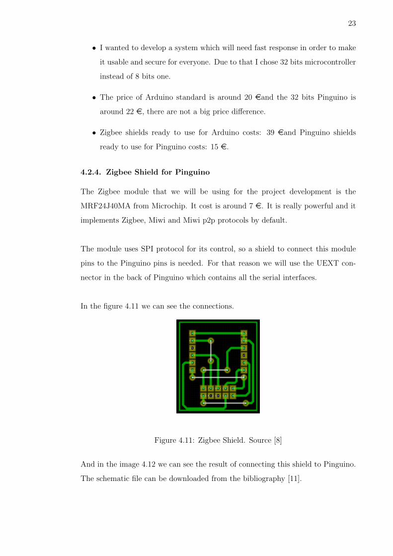
4.2.4. Zigbee Shield for Pinguino
The Zigbee module that we will be using for the project development is the
MRF24J40MA from Microchip. It cost is around 7 e. It is really powerful and it
implements Zigbee, Miwi and Miwi p2p protocols by default.
The module uses SPI protocol for its control, so a shield to connect this module
pins to the Pinguino pins is needed. For that reason we will use the UEXT con-
nector in the back of Pinguino which contains all the serial interfaces.
In the figure 4.11 we can see the connections.
Figure 4.11: Zigbee Shield. Source [8]
And in the image 4.12 we can see the result of connecting this shield to Pinguino.
The schematic file can be downloaded from the bibliography [11].
24
Figure 4.12: Zigbee Shield connected to Pinguino. Source [5]
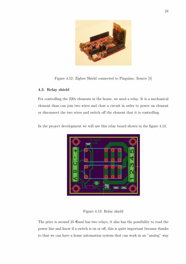
4.3. Relay shield
For controlling the 220v elements in the house, we need a relay. It is a mechanical
element than can join two wires and close a circuit in order to power an element
or disconnect the two wires and switch off the element that it is controlling.
In the project development we will use this relay board shown in the figure 4.13.
Figure 4.13: Relay shield
The price is around 25 eand has two relays, it also has the possibility to read the
power line and know if a switch is on or off, this is quite important because thanks
to that we can have a home automation system that can work in an ”analog” way

25
(using the switches) or with the web based application.
220v pin description:
1. Light phase input
2. Light neutral input
3. Light neutral output
4. 220v phase input
5. Light phase output
Interface shield pin description:
• A: 220v light sensor input
• B: Light turn on
• C: Light turn off
Board power:
• - : GND
• +: 12V
The schema and interconnection is described in the following pages.
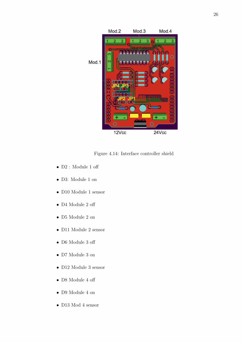
4.4. Interface controller board
Normally, the relays can have different voltage inputs but the most common ones
are the 12V relays. Pinguino works at 3.3V so we need to have a intermediate
board that converts this 3.3V to 12V. This is the functionality of the interface
controller board.
Image 4.14 shows the appearance.
Pin description board:
26
Figure 4.14: Interface controller shield
• D2 : Module 1 off
• D3: Module 1 on
• D10 Module 1 sensor
• D4 Module 2 off
• D5 Module 2 on
• D11 Module 2 sensor
• D6 Module 3 off
• D7 Module 3 on
• D12 Module 3 sensor
• D8 Module 4 off
• D9 Module 4 on
• D13 Mod 4 sensor
27
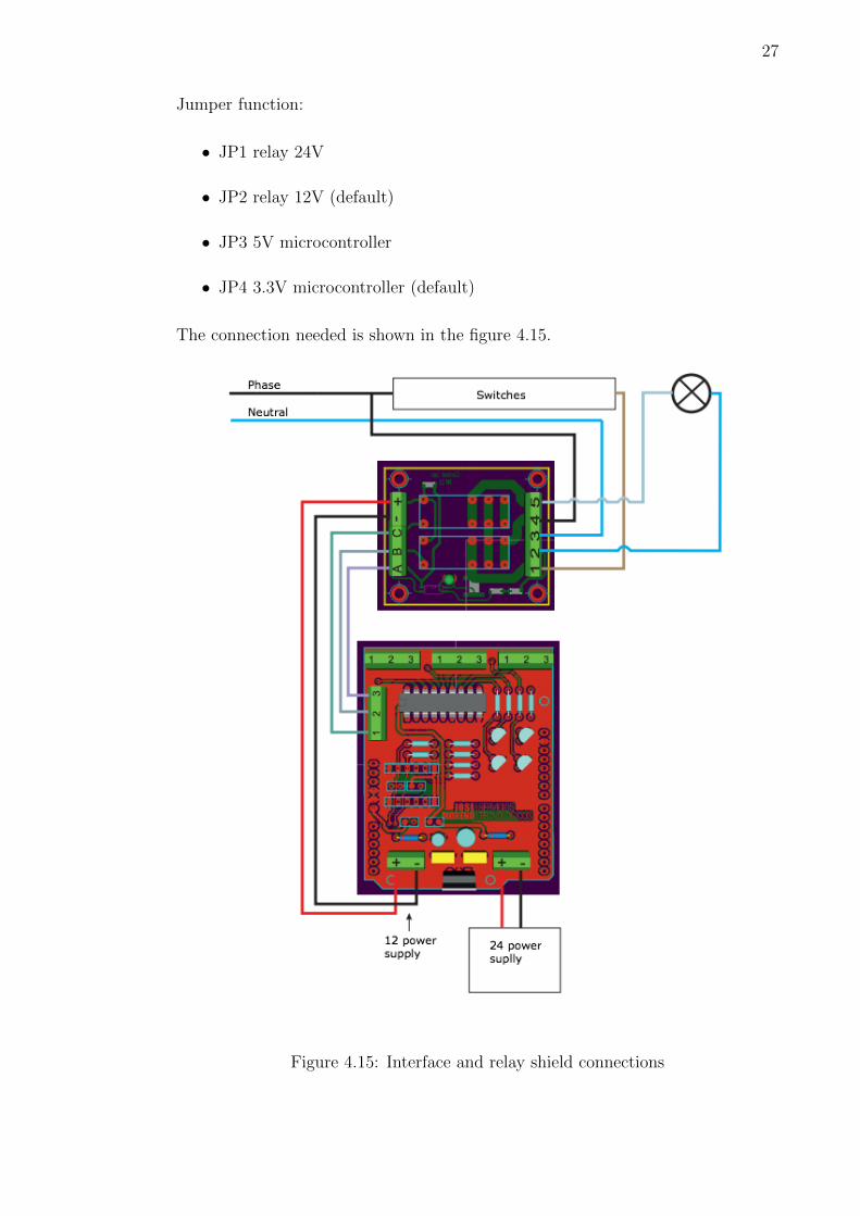
Jumper function:
• JP1 relay 24V
• JP2 relay 12V (default)
• JP3 5V microcontroller
• JP4 3.3V microcontroller (default)
The connection needed is shown in the figure 4.15.
Figure 4.15: Interface and relay shield connections

28
4.5. Mister House
Mister House [6] is a well known Open Source project for home automation base
on X-10 protocol. It is written in Perl and can work on Windows platforms, Mac
OSx and Linux.
Figure 4.16: Mister House logo. Source [6].
It has the most interesting characteristics talking about home automation:
• The software has a web interface, so all the orders can be done with a mobile
phone, smart phone, internet tablet and in general with every device that
has a web browser.
• Opening the port 8080 (where the web server is listening) in the house router,
allows controlling the system out of the house, it is said, world wide.
• Mister House can communicate with X-10 devices, some KNX devices, and
also it has the possibility to create new modules, so the developers can create
their own devices that can interact with Mister House in the same way that
market products can do.
• It can execute actions based on scheduled (Every morning turn on the bed-
room light).
• It can execute actions based on events (When there is enough sun light turn
off the lights).
In the figure 4.17, we can see the appearance of the web interface.

29
Figure 4.17: Mister House web interface 1
5. PROJECT DEVELOPMENT
5.1. Architecture
Figure 5.1: Architecture diagram
The system is composed from 3 different parts:
• Slave firmware: the slaves should be able to discover its master and initialize
a connection with it. Ones it is authenticated, the slave should be ready to
receive instructions from the master, to execute them and to send the new
30
status.
Slave devices will be controlling the elements of the house like lights, mi-
crowave, fridge, etc and for that they need to have an interface board and
as many relay shields as elements it is going to control.
• Master firmware: the master will be connected to the computer or the main
station via USB and wireless with Zigbee with the rest of the slaves. It will
be listening to the air looking for zigbee packages that include instructions
(the zigbee instructions will be described in the following subsections) and
also waiting for instructions that Mister House will send using USB.
When the master device receives an action from usb, it firstly searches for
the destination address of this action, if it is for him, it does it. If not, it
will search if it knows the Zigbee address of this device (because before this
device has been authenticated in the system) and will send to it the action.
The master device can also be an slave device in the sense that it can also
control real devices like lights. If this is the scenario that we want to imple-
ment, it should also have the interface board and the relay shield necessaries.
• Mister House library: thanks to the flexibility of the Open Source software,
we will write a library that helps Mister House to control elements inside of
our network, it means that with Mister House (Home Automation system)
we can control the master and also the slave devices.
Mister House will send information to the USB and the master device will
make a decision about what to do with the packet that it has received.
All the devices are identified by an unique identification called ”House Code”.
31
Typically this code is a letter and can go from A to Z. Although the letter M is
always reserved for the Master device.
It is very important that every device has a different identification (House Code)
from the rest, because otherwise it won’t be able to be attached to the network.
Every house element that is being controlled by a master or a slave device has to
have also a identification number, this identification is called ”Key Code”. It is
a numeric identification and goes from 1 to 99, it means that one slave/master
cannot control more than 99 elements (sensors, lights,...).
The last parameter needed to understand how the system works is the Actions.
They can have different lengths and they are usually written in capital letters.
Some examples of actions are: ON, OFF. All the elements should response always
to the action: STATUS, which will send back the status of this element. In Light
this status is a 0-255 value meaning that 0 is off and 255 is full bright.
This is a complete example of a frame instruction to the element 4 attached to the
device A, asking the device to turn on:
A04ON
32
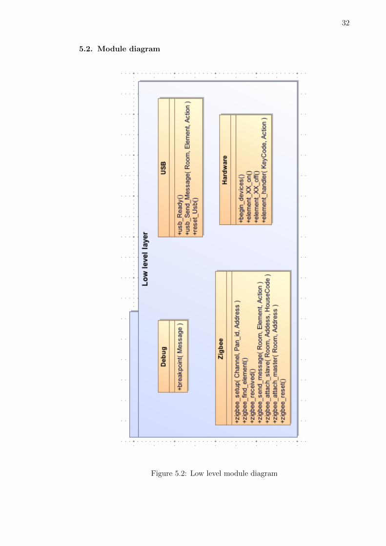
5.2. Module diagram
Figure 5.2: Low level module diagram
33
In the figure 5.2 we can see the low level module diagram of the firmware that are
used in master and slave devices. It is composed of 4 modules: Debug, Hardware,
USB and Zigbee.
5.2.1. Debug
It is one of the most important modules while the system is being developed. It
only contains one function:
void breakpoint(char * Msg);
This function will send the debug information message through serial port or usb,
depending on the system that we were debugging in order to see if the system was
working correctly and if all the information was well received and sent.
5.2.2. Hardware
This module controls the I/O ports of the Microcontroller, all the configuration
needed to success controlling the interfaces are done here, also this module control
the activation and deactivation of the interfaces.
It contains these functions:
• void begin_devices();
It sets up all the the I/O ports of the microcontroller.
The information about what pins it should set as input or output is written
in defines.h header.
• void element_XX_on();
XX means interfaces from 1 to 4, in the future if a new interface board
has more than 4 interfaces, it will be necessary to implement the new ele-
ment XX on functions.
This function is called by default when the element XX of the device receives
the action ”on”. It is said by default because we will see in the following

34
subsections that an end-user or developer can create their own drivers for
controlling the interfaces.
The function acts according functionality of the Interface board data sheet
for turning on the light connected to the interface module XX.
• void element_XX_off();
The functionality is exactly the same as element XX on but instead of turn-
ing of the light attach to this interface module, it switches off.
• void element_handler(KeyCode,Action);
This function will decide to which function should call regarding to the input
information. With the Key Code it knows what kind of element is attached.
An example coming to this function could be: KeyCode: 3; Action: ”ON”.
In this case element handler will call to the function element 3 on().
5.2.3. USB
This module manages the communication layer for usb. All the data that come
and goes to usb will be process by this module.
• boolean usb_ready();
This function returns true when usb has received a complete and valid frame
which contains an instruction. Internally this code reads usb buffer and
checks if the frame is complete or it still needs to receive some more infor-
mation. Once the frame is ready it returns true.
• void usb_Send_Message(char Room, short int Element, char * Action);
This procedure will send an action frame to a element controlled by a room.
It will use the utils.c module to create a correct frame structure.
Mostly this function is used by the master device to inform Mister House
about changes in the network (such as light states changes).
35
• void reset_Usb;
It clears all the buffer used by usb, it is called when the executing of a frame
has finished or when usb has received an invalid frame.
5.2.4. Zigbee
This function will manage all the incoming and outgoing information using the
wireless protocol. It also contains a list data structure and some function for con-
trol that will be explained above.
It is one of the most important modules of the system. It will create the mesh
network, will attach devices and will track all the packet in order to have a good
quality of service.
• void zigbee_setup();
It initializes all the registers and I/O ports necessaries for Zigbee microchip
board.
• boolean zigbee_find_element(char HouseCode);
This module internally maintains a data structure and it is there where it
stores the addresses corresponding to the House Code of the devices. This
data structure is very important because without it, the device will be un-
available of sending data using Zigbee.
This function is called when the master wants to send a package to a slave.
It is the first step in the procedure, firstly it has to know where it has to send
the package. The function will return true if the master has the address of
the slave in the data structure. False otherwise.
• boolean zigbee_received();
This function is quite similar to usb ready but for Zigbee. It returns true
when Zigbee has received a complete and valid frame which contains an
36
instruction. Internally this code reads usb buffer and checks if the frame is
complete or it still needs to receive some more information. Once the frame
is ready it returns true.
• void zigbee_send_message(char Room, short int Element, char * Action);
This function will send a packet using the frame structure defined by our
system to the device that has the House Code equals to Room.
Prior to sending the packet the function searches if it has the address of the
device with the House Code equals to Room, if it has it, it retrieves the
address. Then it composes a frame with the defined structure and it is then
when it is ready to send the packet.
• void zigbee_attach_master(char Room, short int Address);
This function is called when the slave sends a packet to the master indicating
that it wants to be part of the network.
From this packet it will extract the device address and the House Code.
One possible state of this data structure could be this:
A → 0x0001h
B → 0x0003h
D → 0x0004h
• void zigbee_reset();
It will reset all the buffer used for Zigbee communications, it can happen
for 2 reasons, the frame was invalid or the device has finished executing the
instruction.

37
Figure 5.3: High level module diagram
38
In the figure 5.3 we can see the high level module diagram of the firmware that
are used in master and slave devices. It is composed of 4 modules: Utils, Protocol
and Control.
5.2.5. Utils
This module doesn’t have an specific task but helps to group some functions that
are commons in different modules and it is very important that the functions used
in the different modules have the same, otherwise the protocol could stop working.
Having this function grouped in a single module has one advantage and it is that
if a change in the frame structure is done, we only have to change these functions.
• char * frame(char Room, short int Element, char * Action);
This function will send back after the call a valid frame structure using the
Room code, the Element (KeyCode) code and the action.
• char * frame_confirmation(char Room, short int Element);
It is quite similar to the last one but this function will create a confirmation
frame that are used when an action has been done but one slave. Detail
about how the protocol works will be described in the next subsections.
5.2.6. Protocol
This module is in charge of making the decision about what to do when something
in the device happen, it goes from received a packet to connect to the slave.
All the functionalities about what to do when an scenario shows up is written in
these function.
There are different protocols depending if the device is a master or a slave and in
the master, there are also a protocol for Zigbee and another for USB.
Internally this module has a data structure where it saves the instruction that has
been sent and which it didn’t receive a reply. If the device doesn’t reply during

39
severals tries it can be dropped out of the network.
• void add_packet(char HouseCode, short int KeyCode,
char * Action);
As its name says, it inserts an entry in the data structure telling that a packet
has been sent to the HouseCode device and KeyCode element with an Action.
The data structure is a dynamic linked list, so the list will be growing if we
don’t receive answers from the devices that we send packet.
• void delete_task(char HouseCode, short int KeyCode);
This function deletes all the entries in the linked list related to the device
HouseCode and KeyCode element.
For example if we have sent several packets to the device in the kitchen
(HouseCode : K) telling it that it should turn off the light controlled by the
element 3 (KeyCode: 3), the call function will be like that:
delete_task(’A’,3);
• void delete_task(char * Action);
It is similar to the last one, but this one will delete the entries that contain
the same Action. It is used in an scenario like the following:
We send the instruction turn on to the element 3 in the device A, but we
didn’t receive a confirmation that the action has been done. In this moment,
we decide to turn off this same element in this same device, so what we do
is delete all the instruction with the action ’ON’ to avoid the turning on of
the element. Doing that we avoid the device to turn on and the turn off
immediately.
• void show_pending();
40
It was made only for debugging purposes, when it is called it sends back to
the usb the number of packet that hasn’t been delivered yet.
• void slave_protocol(char HouseCode, short int KeyCode,
char * Action);
This is the protocol used by the slave devices.
The scenario that it covers will be described in the following subsections .
• void master_usb_protocol(char HouseCode, short int KeyCode,
char * Action);
This is the protocol used by the master device when an event has raised up
in the USB.
• void master_zigbee_protocol(char HouseCode, short int KeyCode,
char * Action);
This is the protocol used by the master device when an event has raised up
in Zigbee.
5.2.7. Control
• void decompress(char * Frame, char *HouseCode,
short int * KeyCode, char * Action);
This function will receive a valid frame that has arrived from USB or Zigbee
and it will extract the House Code, the Key Code and the Action.
Ones we have this information we can make a decision about what to do.
• void execute(char * Frame);
Receive a frame and execute the action.
• void run_zigbee();
41
Check if there is something new in Zigbee, if so, it calls to execute() to make
the execution process.
• void run_usb();
Similar to the last one but in this case it checks if there is something new in
USB.
• void run();
Ask for all the interfaces available in the system (in our case, run usb and
run zigbee). If in the future we implement another communication protocol,
here it will has to appear a run new protocol that will look if something have
been received by this new communication protocol in order to execute it.
5.3. Protocols
5.3.1. Slave protocol
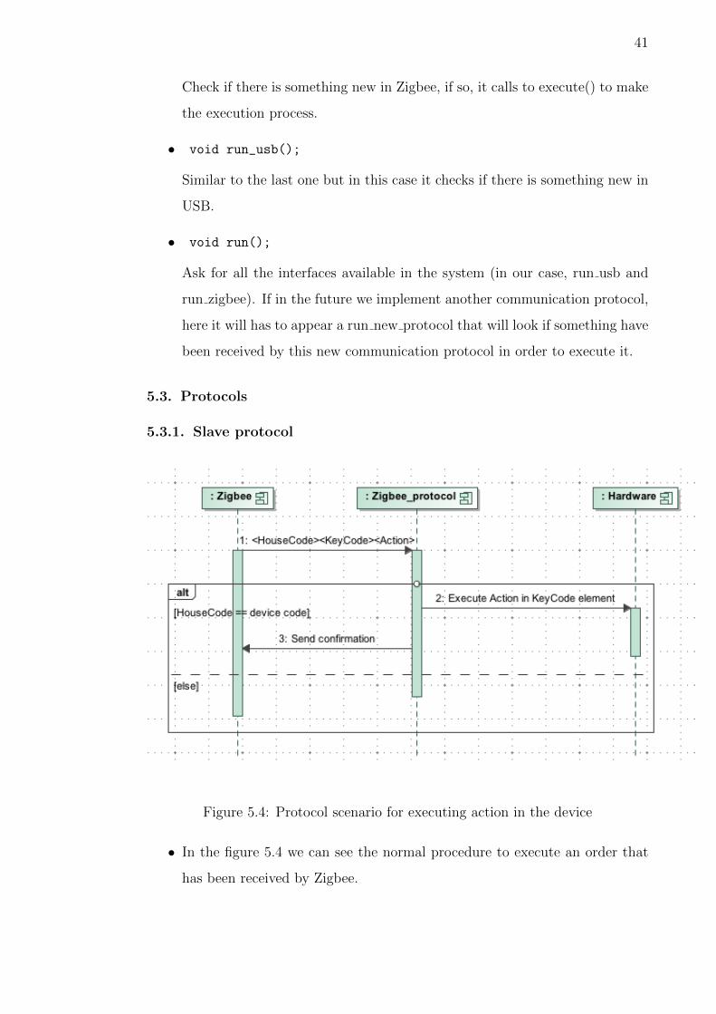
Figure 5.4: Protocol scenario for executing action in the device
• In the figure 5.4 we can see the normal procedure to execute an order that
has been received by Zigbee.

42
Note that the confirmation is very important, if we don’t do that, every
timeout is reached by the master device, it will send the same packet again,
this will not cause any action in the slave device because it already has this
state but, the network will have not useful traffic.
Figure 5.5: Protocol scenario for connection successful.
• In the figure 5.5 we can see the message received from the master indicating
that the device is not attached to the network.
It is only done once when the device turns on, it is received after the slave
sends a packet to initialize the authentication in the home network.
• In the figure 5.6 we can see that one slave has received a packet and the House
Code doesn’t match with its HouseCode, so it will search in the internal
memory if it has the address of the device and if it has it, it will send it back
to it.
This function was implemented because some Zigbee devices are not able to
build a mesh network on their own, so this function is needed, but in our
case it is not necessary.

43
Figure 5.6: Protocol scenario for retransmitting a packet.
5.3.2. USB master protocol
• In the figure 5.7 we can see the normal procedure to execute an order that
has been received by USB.
• In the figure 5.8 we see the flows of information between the different modules
when from USB, the master device is asked about what devices are attached
to its network.
This information can be used for debugging and also for future jobs that can
be done in the project.
We have to ask from Zigbee protocol about how many devices are connected
because it is the one that track all the connection between the master and
the slaves.

44
Figure 5.7: Protocol scenario of executing an action coming from USB.
Figure 5.8: Protocol scenario for retrieving connected slaves.
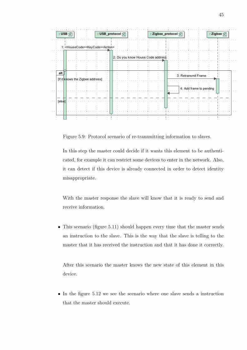
• In the figure 5.9 we see the scenario for re-transmitting a packet from the
master (that has received it by USB) to a Slave via Zigbee communications.
The packet is added to the linked list once it has been sent and if after a
time it doesn’t receive a confirmation, it will send it again.
5.3.3. Zigbee master protocol
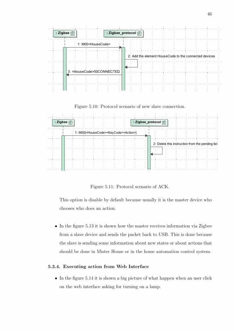
• In the figure 5.10 it is shown the slave connection scenario.
45
Figure 5.9: Protocol scenario of re-transmitting information to slaves.
In this step the master could decide if it wants this element to be authenti-
cated, for example it can restrict some devices to enter in the network. Also,
it can detect if this device is already connected in order to detect identity
misappropriate.
With the master response the slave will know that it is ready to send and
receive information.
• This scenario (figure 5.11) should happen every time that the master sends
an instruction to the slave. This is the way that the slave is telling to the
master that it has received the instruction and that it has done it correctly.
After this scenario the master knows the new state of this element in this
device.
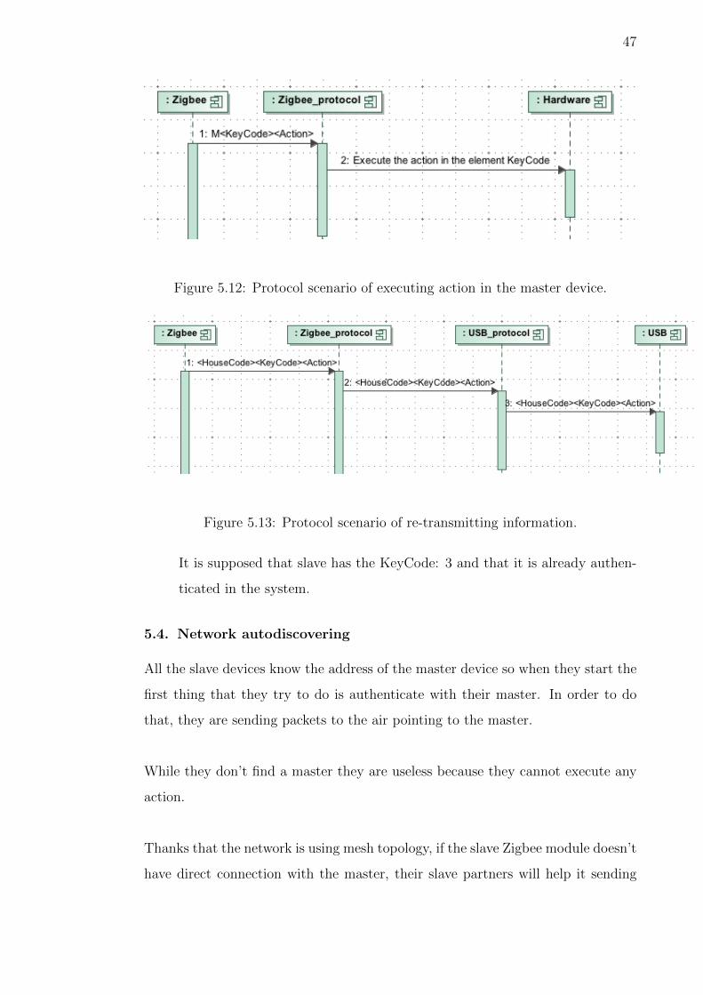
• In the figure 5.12 we see the scenario where one slave sends a instruction
that the master should execute.
46
Figure 5.10: Protocol scenario of new slave connection.
Figure 5.11: Protocol scenario of ACK.
This option is disable by default because usually it is the master device who
chooses who does an action.
• In the figure 5.13 it is shown how the master receives information via Zigbee
from a slave device and sends the packet back to USB. This is done because
the slave is sending some information about new states or about actions that
should be done in Mister House or in the home automation control system.
5.3.4. Executing action from Web Interface
• In the figure 5.14 it is shown a big picture of what happen when an user click
on the web interface asking for turning on a lamp.
47
Figure 5.12: Protocol scenario of executing action in the master device.
Figure 5.13: Protocol scenario of re-transmitting information.
It is supposed that slave has the KeyCode: 3 and that it is already authen-
ticated in the system.
5.4. Network autodiscovering
All the slave devices know the address of the master device so when they start the
first thing that they try to do is authenticate with their master. In order to do
that, they are sending packets to the air pointing to the master.
While they don’t find a master they are useless because they cannot execute any
action.
Thanks that the network is using mesh topology, if the slave Zigbee module doesn’t
have direct connection with the master, their slave partners will help it sending

48
Figure 5.14: Executing action from Web Interface.
its packets to the master.
5.5. Drivers
The drivers of the elements are the components that say what a element has to
do. By default all the drivers are focused on controlling lamps using the Interface
Board and the Relay Board, so, when the driver of a element X is called, it changes
the outputs in order to turn on or off this light that it is controlling.
When the system is being used by default for controlling lamps there is no need to
implement new drivers, but if a developer has created another application for an
interface, he/she may has decided to implement a different driver for this interface.
In that case, it should define the drivers like this:
#define INTERFACE 1
void hw_beginDevices(){
//It defines all the pin mode configuration (INPUT or OUTPUT)
}

49
void hw_element0_on(){
//Driver example of the action "on" on the element 0
}
5.6. Mister House library
The library for the connection of Mister House with Pinguino is written in Perl
because Mister House is written in Perl and it was easier to have everything work-
ing.
It is composed of two main functions:
• sub startup {}
This function sets up the serial connection once Mister House has started.
The serial connection is saved in a variable in order that we can re-use it
every time we want without creating a new connection to the serial port
again.
• sub send_X10 {}
This function is the one in charge of sending the instruction that the end
user has order via web interface to the Pinguino Master via USB.
The installation and configuration of Mister House can be found in the project
web page [6].
6. CONCLUSIONS
This project has been really interesting, I have learned a lot of things related with
wireless networks, home automation protocols and now that it is finished I am
glad to say that this system can be implemented in real houses.
At the beginning it was completely surprised about how many things it has been
done for home automation but that they are not really secure or that can bring
with a lot of problems in the future.
50
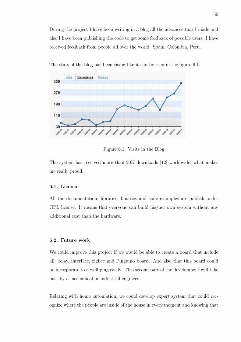
During the project I have been writing in a blog all the advances that I made and
also I have been publishing the code to get some feedback of possible users. I have
received feedback from people all over the world: Spain, Colombia, Peru.
The stats of the blog has been rising like it can be seen in the figure 6.1.
Figure 6.1: Visits in the Blog
The system has received more than 20K downloads [12] worldwide, what makes
me really proud.
6.1. Licence
All the documentation, libraries, binaries and code examples are publish under
GPL license. It means that everyone can build his/her own system without any
additional cost than the hardware.
6.2. Future work
We could improve this project if we would be able to create a board that include
all: relay, interface, zigbee and Pinguino board. And also that this board could
be incorporate to a wall plug easily. This second part of the development will take
part by a mechanical or industrial engineer.
Relating with home automation, we could develop expert system that could rec-
ognize where the people are inside of the house in every moment and knowing that

51
we could shut down lights or turn them automatically without switches.
Having the possibility to control specifics task of elements of the house (microwave,
fridge, doors, ...) would be also a great feature. With our system we can turn them
on or off but we cannot say to the microwave for example turn on running a de-
terminate time/power.
Connection with house cleaning robots would be also really good to improve the
quality of living. We could say to this robot to turn on just when we leave to the
job, and it can be cleaning till we arrive home.
52
7. Bibliography
References
[1] X-10 specification
ftp://ftp.x10.com/pub/manuals/technicalnote.pdf
[2] ZigBee Alliance web page
http://www.zigbee.org/
[3] J. Jun, M.L. Sichitiu, ”The nominal capacity of wireless mesh networks”, in
IEEE Wireless Communications, vol 10, 5 pp 8-14. October 2003
[4] S.M. Chen, P, Lin, D-W Huang, S-R Yang, ”A study on distributed/central-
ized scheduling for wireless mesh network” in Proceedings of the 2006 Inter-
national Conference on Wireless Communications and Mobile Computing, pp
599 - 604. Vancouver, British Columbia, Canada. 2006
[5] Pinguino project web page
http://www.pinguino.cc
[6] Mister House project web page
http://misterhouse.sourceforge.net/
[7] Pinguino 32 schematics
http://www.pinguino.cc/download/schematics/PIC32-PINGUINO/
PIC32-PINGUINO-schematic.pdf
[8] MRF24J40MA for Pinguino documetation
http://wiki.pinguino.cc/index.php/With-Zigbee-MRF24J40MA%2B
[9] MRF24J40MA module documentation
http://www.microchip.com/wwwproducts/Devices.aspx?dDocName=
en535967
[10] Zigbee topologies
http://www.jennic.com/elearning/zigbee/files/html/module2/
module2-2.htm

53
[11] Zigbee Shield schematic
http://www.hackinglab.org/pinguino/download/build%20Pinguino/
zigbee/zigbeeshield.brd
[12] Project download page
http://forja.rediris.es/frs/?group_id=414
[13] Arduino project web page
http://arduino.cc
[14] Zigbee Wikipedia page
http://en.wikipedia.org/wiki/ZigBee
[15] Renesas Zigbee specifications
http://am.renesas.com/applications/key_technology/connectivity/
zigbee/index.jsp
[16] X-10 web page
http://www.x10.com/
[17] Home automation figure example
http://www.hacknmod.com/wp-content/uploads/2008/11/
home-automation.jpg