Embed Size (px)
Citation preview
Multi-function wireless routerwith 4-Port Fast Ethernet switch
802.11g WirelessRouter
User’s Guide
WEP-72104Gvers.2
NOTE: This guide covers only the most commonsituations. Please refer to the full UserManual on the Router CD-ROM if your network LAN has any of the following:• another connected router• an existing DHCP Server• PCs using Fixed (Static) IP Addresses


Table of Contents
CHAPTER 1: INTRODUCTION..............................................................................2
Wireless Router Features...................................................................................2Package Contents .............................................................................................4Physical Details ................................................................................................5About the Operation Mode................................................................................7
CHAPTER 2: INSTALLATION ..............................................................................8
Requirements ...................................................................................................8Procedure ........................................................................................................8
CHAPTER 3: SETUP .............................................................................................9
Overview .........................................................................................................9Configuration Program.....................................................................................9Setup Wizard................................................................................................. 11Configuration via Web ................................................................................... 14
CHAPTER 4: PC CONFIGURATION.................................................................... 35
Overview ....................................................................................................... 35Windows Clients ............................................................................................ 35Macintosh Clients........................................................................................... 47Linux Clients................................................................................................. 47Other Unix Systems........................................................................................ 47Wireless Station Configuration........................................................................ 48
APPENDIX A TROUBLESHOOTING ....................................................... 49
Overview ....................................................................................................... 49General Problems........................................................................................... 49Internet Access ............................................................................................... 49Wireless Access............................................................................................... 50
APPENDIX B ABOUT WIRELESS LANS.................................................. 51
Modes ........................................................................................................... 51BSS .............................................................................................................. 51Channels ....................................................................................................... 51WEP............................................................................................................. 52Wireless LAN Configuration ........................................................................... 52
APPENDIX C SPECIFICATIONS ......................................................................... 53
Multi-Function Wireless Router....................................................................... 53Wireless Interface ........................................................................................... 53Regulatory Approvals ..................................................................................... 54

2
Chapter 1: IntroductionCongratulations on the purchase of your new Unicom 802.11g Wireless Router. Unicom’sWireless Router is a multi-function device providing the following services:
• Shared Broadband Internet Access for all LAN users.
• 4-Port Switching Hub for 10Base-T or 100Base-T connections.
• Wireless Access Point for 802.11b and 802.11g Wireless Stations.
Wireless Router Features
Unicom's 802.11g Wireless Router incorporates many advanced features, carefully designed toprovide sophisticated functions while being easy to use.
Internet Access Features
• Shared Internet Access. All users on the LAN or WLAN can access the Internetthrough the Wireless Router, using only a single external IP Address. The local (invalid)IP Addresses are hidden from external sources. This process is called NAT (NetworkAddress Translation).
• DSL & Cable Modem Support. The Wireless Router has a 10/100Base-T Ethernetport for connecting a DSL or Cable Modem. All popular DSL and Cable Modems aresupported. SingTel RAS and Big Pond (Australia) login support is also included.
• PPPoE, and PPTP. The Internet (WAN port) connection supports PPPoE (PPP overEthernet), PPTP (Peer-to-Peer Tunneling Protocol), as well as "Direct Connection" typeservices. Unnumbered IP with PPPoE is also supported.
• Fixed or Dynamic IP Address. On the Internet (WAN port) connection, the WirelessRouter supports both Dynamic IP Address (IP Address is allocated on connection) andFixed IP Address.
Advanced Internet Functions
• Communication Applications. Support for Internet communication applications, suchas interactive Games, Telephony, and Conferencing applications, which are often difficultto use when behind a Firewall, is included.
• Special Internet Applications. Applications that use non-standard connections or portnumbers are normally blocked by the Firewall. Application support is provided allowingsuch applications to be used normally.

3
• Virtual Servers. This feature allows Internet users to access Internet servers on yourLAN. The required setup is quick and easy.
• DDNS Support. DDNS (Dynamic DNS) allows Internet users to connect to VirtualServers on your LAN using a domain name, even if your IP address is not fixed.
• DMZ. For each WAN (Internet) IP address allocated to you, only one (1) PC on yourlocal LAN can be configured to allow unrestricted 2-way communication with Servers orindividual users on the Internet. This provides the ability to run programs that areincompatible with Firewalls.
• URL Filter. Use the URL Filter to block access to undesirable Web sites by LAN users.
• Internet Access Log. See which Internet connections have been made.
• Access Control. Using the Access Control feature, you can assign LAN users todifferent groups, and determine which Internet services are available to each group.
• VPN Pass through Support. PCs with VPN (Virtual Private Networking) softwareusing PPTP, L2TP and IPSec are transparently supported - no configuration is required.
Wireless Features
• Standards Compliant. The Wireless Router complies with the IEEE802.11g (DSSS)specifications for Wireless LANs.
• Supports both 802.11b and 802.11g Wireless Stations. The 802.11g standardprovides for backward compatibility with the 802.11b standard, so that both 802.11b and802.11g Wireless stations can be used simultaneously.
• Speeds to 54Mbps. All speeds up to the 802.11g maximum of 54Mbps are supported.
• WEP support. Support for WEP (Wired Equivalent Privacy) is included. Key sizes of64 Bit and 128 Bit are supported.
• Wireless MAC Access Control. The Wireless Access Control feature can check theMAC address (hardware address) of Wireless stations to ensure that only trusted WirelessStations can access your LAN.
• Simple Configuration. If the default settings can be changed quickly and easily.
LAN Features
• 4-Port Switching Hub. The Wireless Router incorporates a 4 Port 10/100Base-Tswitching hub, making it easy to create or extend your LAN.
• DHCP Server Support. Dynamic Host Configuration Protocol provides a dynamic IPaddress to PCs and other devices upon request. The Wireless Router can act as a DHCPServer for devices on your local LAN and WLAN.
Configuration & Management
• Easy Setup. Use your WEB browser from anywhere on the LAN or WLAN forconfiguration.
• Configuration File Upload/Download. Save (download) the configuration data fromthe Wireless Router to your PC, and restore (upload) a previously saved configuration fileto the Wireless Router.
• Remote Management. The Wireless Router can be managed from any PC on yourLAN. If an Internet connection exists, the router can also be configured via the Internet.
• Network Diagnostics. The Wireless Router can perform a Ping or DNS lookup.
• UPnP Support. UPnP (Universal Plug and Play) allows automatic discovery andconfiguration of the Wireless Router. UPnP is by supported by Windows ME, XP, orlater.

4
Security Features
• Password-protected Configuration. Optional password protection is provided toprevent unauthorized users from modifying the configuration data and settings.
• Wireless LAN Security. WEP (Wired Equivalent Privacy) is supported, as well asWireless access control to prevent unknown wireless stations from accessing your LAN.
• NAT Protection. An intrinsic side effect of NAT (Network Address Translation)technology is that by allowing all LAN users to share a single IP address, the location andeven the existence of each PC is hidden. From the external viewpoint, there is no network,only a single device - the Wireless Router.
• Protection against DoS attacks. DoS (Denial of Service) attacks can flood yourInternet connection with invalid packets and connection requests, using so muchbandwidth and so many resources that Internet access becomes unavailable. The WirelessRouter incorporates protection against DoS attacks.
Package Contents
The following items are included:• The Wireless Router Unit• Power Adapter• Quick Installation Guide• CD-ROM containing the online manual.
If any of the above items are damaged or missing, please contact your dealer immediately.

5
Physical Details
Front-mounted LEDs
Figure 1: Front Panel
Power LED On - Power on.
Off - No power.
Internet LED On - Connection to the Broadband Modem attached to the WAN(Internet) port is established.
Off - No connection to the Broadband Modem.
Flashing - Data is being transmitted or received via the WAN port.
WLAN LED On - Wireless connection available; Wireless Access Point is ready foruse.
Off - No Wireless connection available.
Flashing - Data is being transmitted or received via the Wireless accesspoint. Data includes "network traffic" as well as user data.
LAN LEDs For each port, there are 2 LEDs
• Link/Act light
On - Corresponding LAN (hub) port is active.
Off - No active connection on the corresponding LAN (hub) port.
Flashing - Data is being transmitted or received via thecorresponding LAN (hub) port.
• 100 light
On - Corresponding LAN (hub) port is using 100Base-T.
Off - Corresponding LAN (hub) port connection is using 10Base-T,or no active connection.

6
Rear Panel
Figure 2: Rear Panel
Power port Connect the supplied power adapter here.
10/100Base-TLAN port
Use standard LAN cables (RJ45 connectors) to connect your PCs tothese ports.
If required, any port can be connected to another hub. Any LAN portwill automatically function as an "Uplink" port when necessary.
Internet port(10/100Base-T)
Connect the DSL or Cable Modem here. If your modem came with acable, use the supplied cable. Otherwise, use a standard LAN cable.
Reset Button This button has two (2) functions:• Reboot. When pressed within 3~5 seconds, the power LED
lights amber. When released, the Wireless Router will reboot(restart).
• Clear All Data. This button can also be used to clear ALL dataand restore ALL settings to the factory default values.
To Clear All Data and restore the factory default values:1. After Power On.2. Hold the Reset Button down.3. Keep holding the Reset Button more than 5 seconds, until the
Amber LED has flashed.
4. Release the Reset Button. The Wireless Router is now using thefactory default values.
7
About the Operation Mode
AP Mode
When acting as an access point, this device connects all the remote stations (Desktop/notebookPC with wireless network adapter) to a wired network. All stations can have Internet accessprovided the Access Point has an Internet connection.
Bridge Mode
The WDS (Wireless Distributed System) function lets this access point act as a wireless LANaccess point and repeater at the same time. Users can use this feature to build up a largewireless network in a large space like airports, hotels and schools …etc. This feature is alsouseful when users want to bridge networks between buildings where it is impossible to deploynetwork cable connections between these buildings.
Repeater
Refer to the illustration below. While acting as a Bridge, AP1 (Station 1) and AP2 (Station 2)can communicate with each other through wireless interface (with WDS). Thus Station 1 cancommunicate with Station 2 and both Station 1 and Station 2 are able to access the Interneteven if only one of the stations has the Internet connection.
To set the operation mode to Bridge, please go to “Wireless ����Basic Settings”, in the“Mode” field click the down arrow � to select AP mode. And go to “Wireless ����WDSSettings” to enable WDS.

8
Chapter 2: Installation
Requirements
• Network cables. Use standard 10/100Base-T network (UTP) cables with RJ45 connectors.• TCP/IP protocol must be installed on all PCs.• For Internet Access, an Internet Access account with an ISP and either a DSL or Cable
modem (for WAN port usage)• To use the Wireless Access Point, all Wireless devices must be compliant with the
IEEE802.11b or IEEE802.11g specifications.
Procedure
1. Choose an Installation Site• Select a suitable place on the network to install the Wireless Router.
Ensure both the Wireless Router and the DSL/Cable modem are powered OFF.
2. Connect LAN Cables• Use standard LAN cables to connect PCs to the Switching Hub ports on the Wireless
Router. Both 10Base-T and 100Base-T connections can be used simultaneously.• If required, connect any port to a normal port on another Hub, using a standard LAN
cable. Thanks to MDI/MDIX, any LAN port on the Wireless Router will automaticallyfunction as an "Uplink" port when required.
3. Connect WAN Cable• Connect the DSL or Cable modem to the WAN port on the Wireless Router. Use the cable
supplied with your DSL/Cable modem. If no cable is supplied, use a standard RJ45 cable.
4. Power Up• Power on the Cable or DSL modem.• Connect the supplied power adapter to the Wireless Router and power up.
Use only the power adapter provided. Using a different one may cause hardware damage5. Check the LEDs• The Power LED should be ON.• The Status LED should flash, then turn off. If it stays on, there is a hardware error.• For each LAN (PC) connection, the LAN Link/Act LED should be ON (provided the PC
is also ON.)• The WAN LED should be ON.• The WLAN LED should be ON
For more information, refer to Front-mounted LEDs in Chapter 1.

9
Chapter 3: Setup
Overview
This chapter describes the setup procedure for:• Internet Access• LAN configuration• Wireless setup• Assigning a Password to protect the configuration data.
PCs on your local LAN may also require configuration. For details, see Chapter 4 - PCConfiguration.
Other configuration may also be required, depending on which features and functions of theWireless Router you wish to use. Use the table below to locate detailed instructions for therequired functions.
Configuration Program
The Wireless Router contains an HTTP server. This enables you to connect to it and configureit using your Web Browser. Your Browser must support JavaScript.
The configuration program has been tested on the following browsers:• Netscape v4.08 or later• Internet Explorer v4 or later
Preparation
Before attempting to configure the Wireless Router, please ensure that:• Your PC can establish a physical connection to the Wireless Router. The PC and the
Wireless Router must be directly connected (using the Hub ports on the Wireless Router)or on the same LAN segment.
• The Wireless Router must be installed and powered ON.• If the Wireless Router's default IP Address (192.168.1.254) is already used by another
device, the other device must be turned OFF until the Wireless Router is allocated a newIP Address during configuration.
Using UPnP
If your Windows system supports UPnP, an icon for the Wireless Router will appear in thesystem tray notifying you that a new network device has been found and offering to create anew desktop shortcut to the newly-discovered device.• Unless you intend to change the IP Address of the Wireless Router, you can accept the
desktop shortcut.• Whether you accept the desktop shortcut or not, you can always find UPnP devices in My
Network Places (previously called Network Neighborhood).• Double-click the icon for the Wireless Router (either on the Desktop or in My Network
Places) to start the configuration. Refer to the following section, Setup Wizard, for detailsof the initial configuration process.

10
Using your Web Browser
To establish a connection from your PC to the Wireless Router:1. After installing the Wireless Router in your LAN, start your PC. If your PC is already
running, restart it.2. Start your WEB browser.3. In the Address box, enter "HTTP://" and the IP Address of the Wireless Router. The
Wireless Router's default IP Address is as follows:HTTP://192.168.1.254
No username and password are required for the first login (default setting). However, you canassign a set of username and password for future security. See the Password Setup section laterin this chapter for details.
If you can't connect
If the Wireless Router does not respond, check the following:• The Wireless Router is properly installed, LAN connection is OK, and it is
powered ON. You can test the connection by using the "Ping" command:• Open the MS-DOS window or command prompt window.• Enter the command:
ping 192.168.1.254If no response is received, either the connection is not working, or yourPC's IP address is not compatible with the Wireless Router's IP Address.(See next item.)
• If your PC is using a fixed IP Address, its IP Address must be within therange 192.168.1.1 to 192.168.1.253 to be compatible with the WirelessRouter's default IP Address of 192.168.1.254. Also, the Network Mask mustbe set to 255.255.255.0. See Chapter 4 - PC Configuration for details onchecking your PC's TCP/IP settings.
• Ensure that your PC and the Wireless Router are on the same networksegment. (If you don't have a router, this must be the case.)
• Ensure you are using the wired LAN interface. The Wireless interface can onlybe used if its configuration matches your PC's wireless settings.
11
Setup Wizard
The Setup Wizard provides brief and basic configuration of this device, you may enter eachscreen to change the default settings. For more detailed settings, you may refer to the“Configuration via Web” section.1. View the listed configuration items and click Next to continue.
2. Configure Time Zone and NTP server by enabling NTP client update. Click Next tocontinue.
3. Configure the parameters for area network (If you want to change the default parameters) byentering New IP Address and Subnet Mask.
4. Change the access method (Static IP, DHCP, PPPoE or PPTP) by selecting from the pull-down menu. Click Next to continue.

12
5. Configure the parameters for wireless LAN clients. Check the “Disable Access Point” todisable the settings of this screen. Click Next to continue.
6. Manage your wireless network security by selecting the encryption type (None, WEP andWPA (TKIP)) from the pull-down menu. Click Finish to exit Set Wizard screen.

13
Common Connection Types
Cable ModemsType Details ISP Data required
DynamicIP Address
Your IP Address is allocatedautomatically when youconnect to you ISP.
Usually, none. However someISP's may require you to use aparticular Hostname, Domainname, or MAC (physical) address.
Static(Fixed)IP Address
Your ISP allocates apermanent IP Address to you.
IP Address allocated to you.Some ISP's may also require youto use a particular Hostname,Domain name, or MAC (physical)address.
DSL Modems
Type Details ISP Data required
DynamicIP Address
Your IP Address is allocatedautomatically when youconnect to you ISP.
None.
Static (Fixed)IP Address
Your ISP allocates apermanent IP Address to you.
Permanent IP Address allocated.
PPPoE You connect to the ISP onlywhen required. The IP addressis usually allocatedautomatically.
User name and password.
PPTP Mainly used in Europe.
You connect to the ISP onlywhen required. The IP addressis usually allocatedautomatically but may beStatic (Fixed).
• PPTP Server IP Address.• User name and password.• IP Address allocated to
you, if Static (Fixed).
Other Modems (e.g. Broadband Wireless)
Type Details ISP Data required
DynamicIP Address
Your IP Address is allocatedautomatically when you connectto you ISP.
None.
Static (Fixed)IP Address
Your ISP allocates a permanentIP Address to you.
Permanent IP Addressallocated.

14
Configuration via Web
LAN Interface Setup
IP Address Default: 192.168.1.254 (this is the local address of this Router)
Subnet Mask Default: 255.255.255.0
DHCP Disable: Disables this Router from distributing IP Addresses
Server: Enables this Router to distribute IP Addresses (DHCPServer). The following field will be activated to enter thestarting IP Address
DHCP Client Range The starting address of this local IP network address pool.The pool is a piece of continuous IP address segment. Keep thedefault value “192.168.1.1” It should work in most cases.
• Maximum: 253. Default value 253 should workin most cases.
Note: If “Continuous IP address poll starts” is set at192.168.1.1 and the “Number of IP address in pool” is 253,the device will distribute IP addresses from 192.168.1.1 to192.168.1.253 to all the computers in the network that requestIP addresses from DHCP server (Router)
Show Client Click to show Active DHCP Client table.
Save After completing the settings on this page, click Save to savethe settings.
Reset Click Reset to restore to default values.

15
Password Setup
New Password Maximum input is 36 alphanumeric characters (case sensitive)
Confirmed Password Key in the password again to confirm.
Save After completing the settings on this page, click Save to savethe settings.
Reset Click Reset to clear settings.
Status
Internet Shows the Internet connection status
LAN Shows the Local area network information
System Briefly shows the device name and firmware information
Connection Details Click to show more details of the internet connection
System Data Click to show the detailed information of the system
Refresh Screen Click to refresh all the data

16
Wireless
Wireless basic Settings
Disable Access Point Check to disable the AP function.
The wireless (WLAN) LED on front panel will remain OFF ifthe Wireless interface is disabled.
Band You can choose one of the following modes:
� 2.4GHz (B): 802.11b supported rate only.
� 2.4GHz (G): 802.11g supported rate only.
� 2.4GHz (B+G): 802.11b supported rate and 802.11gsupported rate.
The default is 2.4GHz (B+G) mode.
SSID Shows the SSID name.
Channel Number Select the router’s wireless channel (from 1 to 11).
Associated Clients Click to show all the listed active clients.
Save After completing the settings on this page, click Save to savethe settings.
Reset Click Reset to restore to default values.

17
Wireless Advanced Settings
AuthenticationType
Open System: If your access point/wireless router is using "Open" authentication, then the wireless adapter will need to be set to thesame authentication type.
Shared Key: Shared Key is when both the sender and therecipient share a secret key.
Auto: Select Auto Switch for the adapter to automatically selectthe appropriate authentication.
Preamble Type A preamble is a signal used in wireless environments tosynchronize the transmission timing including Synchronizationand Start frame delimiter. (Note: If you want to change thePreamble type into Long or Short, please check the setting ofAP.)
Broadcast SSID Enable: This wireless AP will broadcast its SSID to all stations.
Disable: This wireless AP will not broadcast its SSID to stations. Ifstations want to connect to this wireless AP, its SSID should be knownin advance to make a connection.
Save After completing the settings on this page, click Save to save thesettings.
Reset Click Reset to restore to default values.
Security
Here you can configure the security of your wireless network. Selecting different methods willenable you to have different levels of security. Please note that using any encryption by whichdata packets are encrypted before transmission to prevent undesired eavesdropping, there maybe a significant degradation of the data throughput on the wireless link.
Note: This security function is only enabled under AP mode and Repeater mode.
Encryption: None (Encryption is set to None by default)
If Use 802.1x Authentication is selected, the RADIUS Server will proceed to check the802.1x Authentication.

18
Encryption: WEP
If WEP is selected, users must Set WEP keys either manually or select to Use 802.1xAuthentication to make the RADIUS server issue the WEP key dynamically.
SET WEP KEY• Clicking Set WEP Keys will prompt you to set 64bit or
128bit Encryption.• Select HEX if you are using hexadecimal numbers (0-9,
or A-F). Select ASCII if you are using ASCII characters(case-sensitive).
• Ten hexadecimal digits or five ASCII characters areneeded if 64-bit WEP is used; 26 hexadecimal digits or13 ASCII characters are needed if 128-bit WEP is used.
Encryption: WPA (TKIP)
WPA (TKIP): If WPA is selected, users must select either Enterprise (RADIUS) orPersonal (Pre-shared Key) Authentication modes.
Pre-shared Key Pre-Shared-Key serves as a password. Users may key in a 1to 63 character string to set the password or leave it blank inwhich the 802.1x Authentication will be activated. Make surethe same password is used on the client's end.
There are two Pre-shared key formats, i.e. Passphrase andHex. If Hex is selected, users will have to enter a 64 charactersstring. For easier configuration, the Passphrase (at least 8

19
characters) format is recommended.
Group Key Life Time Enter the number of seconds that will elapse before the groupkey changes automatically. The default is 86400 seconds.
Enable Pre-Authentication
The two most important features standardized through802.11i/WPA2 beyond WPA are: pre-authentication, whichenables secure fast roaming without noticeable signal latency.
Pre-authentication provides a way to establish a PMK securityassociation before a client associates. The advantage is that theclient reduces the time that it is disconnected to the network.
Authentication RADIUSServer
Port: Enter the RADIUS Server’s port number provided byyour ISP. The default is 1812.
IP Address: Enter the RADIUS Server’s IP Address providedby your ISP.
Password: Enter the password that the AP shares with theRADIUS Server.
Save Press to save the new settings on the screen.
Reset Press to discard the current settings.
Site Survey
Site survey displays all the active Access Points and IBSS in the neighborhood.
Refresh Click Refresh to get the latest information.
Connect Click Connect to make a wireless connection.
WDS Settings

20
Enable WDS Check Enable WDS to enable the WDS function.
Add WDS AP MAC Address: Enter the Wireless SSID of the wireless AP thatyou want to connect with. To check your wireless router’s MACaddress, please go to Status and then click the System Databutton to find your MAC address.Comment: Enter a description for the device.
Set Security Enable the WDS function and then click to set the WDSsecurity. For detailed security setup, please refer to the WirelessSecurity mentioned previously.
Show Statistics Click to show the current WDS AP table.
Save Click Save to save the current settings.
Reset Click Reset to clear and reset.
Current WDS AP List Click Current WDS AP List to show the current WDS APinformation.
Delete Selected Click Delete Selected to delete the selected items.
Delete All Click Delete All to delete all the items.
Reset Click Reset to reset.
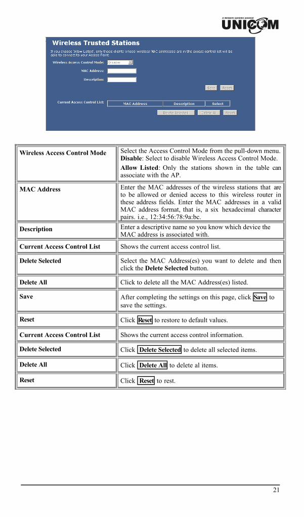
Trusted StationsThe Trusted Stations screen allows you to configure this device to give exclusive access to upto 20 devices. Every Ethernet device has a unique MAC (Media Access Control) address. TheMAC address is assigned at the factory and consists of six pairs of hexadecimal characters, forexample, 00:A0:C5:00:00:02. You need to know the MAC address of the devices to configurethis screen.
21
Wireless Access Control Mode Select the Access Control Mode from the pull-down menu.Disable: Select to disable Wireless Access Control Mode.Allow Listed: Only the stations shown in the table canassociate with the AP.
MAC Address Enter the MAC addresses of the wireless stations that areto be allowed or denied access to this wireless router inthese address fields. Enter the MAC addresses in a validMAC address format, that is, a six hexadecimal characterpairs. i.e., 12:34:56:78:9a:bc.
Description Enter a descriptive name so you know which device theMAC address is associated with.
Current Access Control List Shows the current access control list.
Delete Selected Select the MAC Address(es) you want to delete and thenclick the Delete Selected button.
Delete All Click to delete all the MAC Address(es) listed.
Save After completing the settings on this page, click Save tosave the settings.
Reset Click Reset to restore to default values.
Current Access Control List Shows the current access control information.
Delete Selected Click Delete Selected to delete all selected items.
Delete All Click Delete All to delete al items.
Reset Click Reset to rest.

22
Advanced
WAN Port
WAN Access Type Select the WAN access type (Static IP, DHCP, PPPoE andPPTP) from the pull-down menu.
DNS 1-3 Enter the DNS server IP address(es) provided by your ISPor you can specify your own preferred DNS server IPaddress(es).DNS 1 and DNS 2 servers are optional. You can enteranother DNS server’s IP address as a backup. DNS 1 andDNS 2 servers will be used when the DNS 1 server fails.
Clone MAC Address Your ISP may require a particular MAC address in orderfor you to connect to the Internet. This MAC address isthe PC’s MAC address that your ISP had originallyconnected your Internet connection to. Type in this CloneMAC address in this section to replace the WAN MACaddress with the MAC address of that original PC.
���� Enable uPNP
���� Enable Ipsec pass throughon VPN connection
���� Enable L2TP pass throughon VPN connection
Check to enable the listed functions.
Save After completing the settings on this page, click Save tosave the settings.
Reset Click Reset to restore to default values.

23
Access Control
This screen allows you to block access to specified Internet services based on theport number used. This can be used restrict Internet access to only certainapplications or to block applications you feel may be harmful.
Enable Access Control Select to enable Access Control function.
Select Services to Block This lists all defined Services. Select the Services you wish toblock.
Port Range For TCP and UDP Services, enter the beginning of the range ofport numbers used by the service. If the service uses a singleport number, enter it in both the start and finish fields.
Protocol Select the protocol (TCP, UDP or Both) used to the remotesystem or service.
Description You may key in a description for port range.
Save After completing the settings on this page, click Save to savethe settings.
Reset Click Reset to restore to default values.
Current Blocked Table Shows the current blocked information.
Delete Selected Click Delete Selected to delete selected items.
Delete All Click Delete All to delete all the items.
Reset Click Reset to rest
Dynamic DNS
Dynamic DNS allows you to update your current dynamic IP address with one ormany dynamic DNS services so that anyone can contact you (in NetMeeting, CU-SeeMe, etc.). You can also access your FTP server or Web site on your owncomputer using a domain name (for instance myhost.dhs.org, where my host is aname of your choice) that will never change instead of using an IP address thatchanges each time you reconnect. Your friends or relatives will always be able tocall you even if they don't know your IP address.

24
First of all, you need to have registered a dynamic DNS account with eitherwww.dyndns.org or www.tzo.com. This is for those with a dynamic IP from theirISP or DHCP server that would still like to have a domain name. The DynamicDNS service provider will give you a password or key.
Enable DDNS Check to enable DDNS function.
This free service is very useful when combined with the VirtualServer feature. It allows Internet users to connect to your VirtualServers using a URL, rather than an IP Address. This also solves theproblem of having a dynamic IP address. With a dynamic IP address,your IP address may change whenever you connect, which makes itdifficult to connect to.
Service Provider • Select the desired DDNS Service Provider from the list.• Details of your DDNS account (Name, password, Domain name)
must then be entered and saved on this screen.• This device will then automatically ensure that your current IP
Address is recorded by the DDNS Service Provider.• From the Internet, users will now be able to connect to your
Virtual Servers (or DMZ PC) using your Domain name.
Domain Name Apply for a Domain Name and ensure it is allocated to you.
User Name/Email Enter your Username for the DDNS Service.
Password/key Enter your current password for the DDNS Service.
Result Displays the current results from IP address registration attemptswith the DDNS provider.
Update Click Update to update the screen information.
Reset Click Reset to restore to default values.

25
DMZIf the DMZ Host Function is enabled, it means that you set up DMZ host at a particularcomputer to be openly exposed to the Internet so that some applications/software, especiallyInternet/online gaming can have two-way connections. A device acting as DMZ is notprotected by this device’s firewall.
Enable DMZ If the DMZ Host Function is enabled, it means that you set upDMZ host at a particular computer to be openly exposed to theInternet so that some applications/software, especiallyInternet/online gaming can have two-way connections.
DMZ Host IP Address Enter the IP address of a particular host in your LAN which willreceive all the packets originally going to the WAN port/Public IPaddress above.
Note: You need to give your LAN PC clients a fixed/static IPaddress for DMZ to work properly.
Save After completing the settings on this page, click Save to save thesettings.
Reset Click Reset to restore to default values.

26
DoS SettingDoS (Denial of Service) attacks can flood your Internet connection with invalid packets andconnection requests, occupying so much bandwidth and so many resources that Internet accessbecomes unavailable. The Wireless Router incorporates protection against DoS attacks. Thisscreen allows you to configure DoS protection.
���� Enable DoSPrevention
Select to enable the DoS prevention function.
Enable Source IPBlocking ���� Blocktime (sec)
Set the threshold for the frequency of packets that are allowed to passthrough. The default value is 50 packets per second. You can adjust thevalue according to your need. It is recommended that you set a practicalnumber so that your network performance won’t be hampered.
Select All Click to select all listed items.
Clear All Click to clear all listed items.
Apply Changes Click to save the current settings.
Virtual ServerThe Virtual Server function is a list of inside servers (behind NAT on the LAN), for example,web or FTP, that you can make visible to the outside world even though NAT makes yourwhole inside network appear as a single computer to the outside world. You may enter a singleport number or a range of port numbers to be forwarded and the local IP address of the desiredserver. The port number identifies a service; for example, web service is on port 80 and FTPon port 21. In some cases, such as for unknown services or where one server can support morethan one service (for example both FTP and web service), it might be better to specify a rangeof port numbers. You can allocate a server IP address that corresponds to a port or a range ofports. Many residential broadband ISP accounts do not allow you to run any server processes(such as a Web or FTP server) from your location. Your ISP may periodically check for serversand may suspend your account if it discovers any active services at your location. If you areunsure, refer to your ISP.

27
Enable Virtual Servers Select to enable virtual server function.
Servers You can set up a local server with a specific port number thatrepresents the service (e.g. web (80), FTP (21), Telnet (23)).When this device receives an incoming access request for thisspecific port, it will be forwarded to the corresponding internalserver. You can add virtual servers by either port numbers orby names.
Maximum 24 Server entries are allowed and each port numbercan only be assigned to one IP address.
Local IP Address Enter the Local Server’s IP address.
Protocol Select the protocol (TCP, UDP or Both) used for the remote systemor service.
Port Range For TCP and UDP Services, enter the beginning of the range ofport numbers used by the service. If the service uses a single portnumber, enter it in both the start and finish fields.
Description You may key in a description for the local IP address.
Save After completing the settings on this page, click Save to save thesettings.
Reset Click Reset to restore to default values.
Current Virtual ServersTable
Shows the current virtual servers information.
Delete Selected Click Delete Selected to delete all selected items.
Delete All Click Delete All to delete all the items.
Reset Click Reset to rest
28
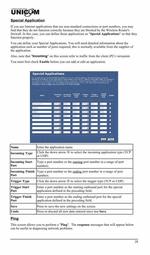
Special Application
If you use Internet applications that use non-standard connections or port numbers, you mayfind that they do not function correctly because they are blocked by the Wireless Router'sfirewall. In this case, you can define those applications as "Special Applications" so that theyfunction properly.
You can define your Special Applications. You will need detailed information about theapplication such as number of ports required; this is normally available from the supplier ofthe application.
Also, note that "Incoming" on this screen refer to traffic from the client (PC) viewpoint.
You must first check Enable before you can add or edit an application.
Name Enter the application name.
Incoming Type Click the down arrow � to select the incoming application type (TCPor UDP)
Incoming StartPort
Type a port number or the starting port number in a range of portnumbers.
Incoming FinishPort
Type a port number or the ending port number in a range of portnumbers.
Trigger Type Click the down arrow � to select the trigger type (TCP or UDP)
Trigger StartPort
Enter a port number as the starting outbound port for the specialapplication defined in the preceding field.
Trigger FinishPort
Enter a port number as the ending outbound port for the specialapplication defined in the preceding field.
Save Press to save the new settings on the screen.
Undo Press to discard all new data entered since last Save.
Ping
This screen allows you to perform a "Ping". The response messages that will appear belowcan be useful in diagnosing network problems.

29
IP Address/Host name
Enter the IP address or domain name that you want to ping.
Run Click to start pinging.
Reset Click to clear the current IP address /Host name.
DiagnosticsThis screen allows you to perform a DNS lookup on any host name you enter. This can beused to help diagnose network problems.
Domain Name/URL Enter the domain name you want to lookup.
Start Lookup Click this button to activate the DNS lookup.
Administration
Remote managementRemote management allows you to remotely configure your Unicom Wireless Router over anInternet connection. Since this is a potential security risk, this feature is turned off by default.Unicom’s Wireless Router can be managed from any PC on your LAN. And, if the Internetconnection exists, it can also (optionally) be configured via the Internet.

30
� Enable web Server Access via WAN Check to enable the function.
Port number Enter the port number.
Save Click to save the current settings.
Reset Click to clear the current settings.
Config File
This feature allows you to download the current settings from the Wireless Router and savethem to a file on your PC.
You can restore a previously downloaded configuration file to the Wireless Router byuploading it to the Wireless Router.
This screen also allows you to set the Wireless Router back to its factory default configuration.Any existing settings will be deleted.
An example Config File screen is shown below.
Backup Config Use this to download a copy of the current configuration andstore the file on your PC. Click Download to start thedownload.
Restore Config This allows you to restore a previously saved configurationfile back to the Wireless Router.
Click Browse to select the configuration file, then clickRestore to upload the configuration file.
WARNING !Uploading a configuration file will destroy (overwrite) ALL ofthe existing settings.
Default Config Clicking the Restore Defaults button will reset the WirelessRouter to its factory default settings.
WARNING !This will delete ALL of the existing settings.
31
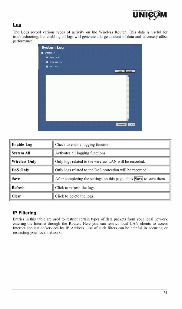
Log
The Logs record various types of activity on the Wireless Router. This data is useful fortroubleshooting, but enabling all logs will generate a large amount of data and adversely affectperformance.
Enable Log Check to enable logging function.
System All Activates all logging functions.
Wireless Only Only logs related to the wireless LAN will be recorded.
DoS Only Only logs related to the DoS protection will be recorded.
Save After completing the settings on this page, click Save to save them.
Refresh Click to refresh the logs.
Clear Click to delete the logs.
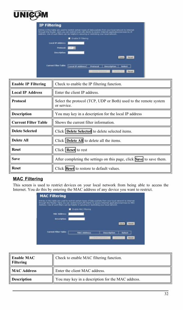
IP FilteringEntries in this table are used to restrict certain types of data packets from your local networkentering the Internet through the Router. Here you can restrict local LAN clients to accessInternet application/services by IP Address. Use of such filters can be helpful in securing orrestricting your local network.
32
Enable IP Filtering Check to enable the IP filtering function.
Local IP Address Enter the client IP address.
Protocol Select the protocol (TCP, UDP or Both) used to the remote systemor service.
Description You may key in a description for the local IP address
Current Filter Table Shows the current filter information.
Delete Selected Click Delete Selected to delete selected items.
Delete All Click Delete All to delete all the items.
Reset Click Reset to rest
Save After completing the settings on this page, click Save to save them.
Reset Click Reset to restore to default values.
MAC FilteringThis screen is used to restrict devices on your local network from being able to access theInternet. You do this by entering the MAC address of any device you want to restrict.
Enable MACFiltering
Check to enable MAC filtering function.
MAC Address Enter the client MAC address.
Description You may key in a description for the MAC address.

33
Current Filter Table Shows the current filter information.
Delete Selected Click Delete Selected to delete all selected items.
Delete All Click Delete All to delete all the items.
Reset Click Reset to reset
Save After completing the settings on this page, click Save to save them.
Reset Click Reset to restore to default values.
Statistics
Refresh Click to refresh the statistics table.
Time Zone Setting
Current Time Enter the current time of this wireless router.
Enable NTP clientupdate
Check to enable NTP (Network Time Protocol Server) clientupdate function.
Time Zone Select Select the time zone from the pull-down menu.
NTP server You may choose to select NTP server from the pull-down menu orenter an IP address of a specific server.
Save After completing the settings on this page, click Save to savethem.
Reset Click Reset to restore to default values.

34
Refresh Click to refresh the current time.
Upgrade Firmware
Browse Click the Browse button to find and open the firmware file. Thebrowser will display to correct file path.
Start Upgrade Click the Start Upgrade button to perform
Reset Click Reset to restore to default values.
Navigation & Data Input
• Use the menu bar on the left of the screen and the "Back" button on your Browser fornavigation.
• Changing to another screen without clicking "Save" does NOT save any changes you mayhave made. You must "Save" before changing screens or your data will be ignored.

35
Chapter 4: PC Configuration
Overview
For each PC, the following may need to be configured:• TCP/IP network settings• Internet Access configuration• Wireless configuration
Windows Clients
This section describes how to configure Windows clients for Internet access via the WirelessRouter.
The first step is to check the PC's TCP/IP settings.
The Wireless Router uses the TCP/IP network protocol for all functions, so it is essential thatthe TCP/IP protocol be installed and configured on each PC.
TCP/IP Settings - Overview
If using the default Wireless Router settings, and the defaultWindows TCP/IP settings, no changes need to be made.
• By default, the Wireless Router will act as a DHCP Server, automatically providing asuitable IP Address (and related information) to each PC when the PC boots.
• For all non-Server versions of Windows, the default TCP/IP setting is to act as a DHCPclient.
If using a Fixed (specified) IP address, the following changes arerequired:• The Gateway must be set to the IP address of the Wireless Router• The DNS should be set to the address provided by your ISP.

36
Checking TCP/IP Settings - Windows 98/ME:
1. Select Control Panel - Network. You should see a screen like the following:
2. Select the TCP/IP protocol for your network card.3. Click on the Properties button. You should then see a screen like the following.
Ensure your TCP/IP settings are correct, as follows:
Using DHCP
To use DHCP, select the radio button Obtain an IP Address automatically. This is the defaultWindows setting. Using this is recommended. By default, the Wireless Router will act as aDHCP Server.
Restart your PC to ensure it obtains an IP Address from the Wireless Router.
Using "Specify an IP Address"
If your PC is already configured, check with your network administrator before making thefollowing changes:
• On the Gateway tab, enter the Wireless Router's IP address in the New Gateway field andclick Add, as shown below. Your LAN administrator can advise you of the IP Addressthey assigned to the Wireless Router.

37
• On the DNS Configuration tab, ensure Enable DNS is selected. If the DNS Server SearchOrder list is empty, enter the DNS address provided by your ISP in the fields beside theAdd button, then click Add.

38
Checking TCP/IP Settings - Windows NT4.0
1. Select Control Panel - Network and on the Protocols tab, select the TCP/IP protocol asshown below.

39
2. Click the Properties button to see a screen like the one below.
3. Select the network card for your LAN.4. Select the appropriate radio button - Obtain an IP address from a DHCP Server or Specify
an IP Address, as explained below.
Obtain an IP address from a DHCP Server
This is the default Windows setting. Using this is recommended. By default, the WirelessRouter will act as a DHCP Server.
Restart your PC to ensure it obtains an IP Address from the Wireless Router.

40
Specify an IP Address
If your PC is already configured, check with your network administrator before making thefollowing changes.
1. The Default Gateway must be set to the IP address of the Wireless Router. To set this:• Click the Advanced button on the screen above.• On the following screen, click the Add button in the Gateways panel, and enter the
Wireless Router's IP address.• If necessary, use the Up button to make the Wireless Router the first entry in the
Gateways list.

41
2. The DNS should be set to the address provided by your ISP, as follows:• Click the DNS tab.• On the DNS screen, shown below, click the Add button (under DNS Service Search
Order), and enter the DNS provided by your ISP.
42
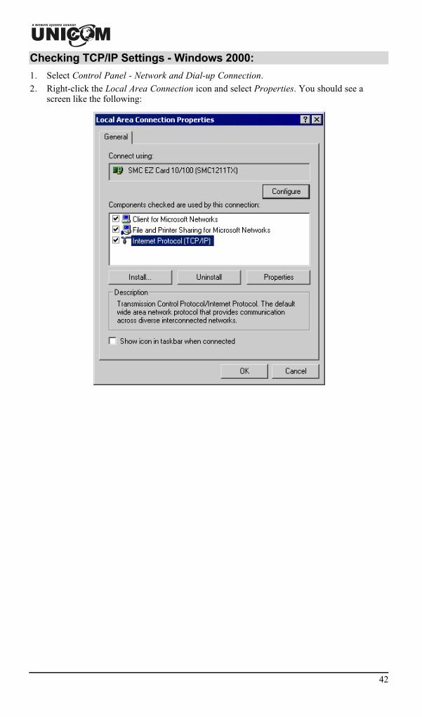
Checking TCP/IP Settings - Windows 2000:
1. Select Control Panel - Network and Dial-up Connection.2. Right-click the Local Area Connection icon and select Properties. You should see a
screen like the following:

43
3. Select the TCP/IP protocol for your network card.4. Click on the Properties button. You should then see a screen like the following.
5. Ensure your TCP/IP settings are correct, as described below.
Using DHCP
To use DHCP, select the radio button Obtain an IP Address automatically. This is the defaultWindows setting. Using this is recommended. By default, the Wireless Router will act as aDHCP Server.
Restart your PC to ensure it obtains an IP Address from the Wireless Router.
Using a fixed IP Address ("Use the following IP Address")
If your PC is already configured, check with your network administrator before making thefollowing changes.• Enter the Wireless Router's IP address in the Default gateway field and click OK. (Your
LAN administrator can advise you of the IP Address they assigned to the WirelessRouter.)
• If the DNS Server fields are empty, select Use the following DNS server addresses, andenter the DNS address or addresses provided by your ISP, then click OK.

44
Checking TCP/IP Settings - Windows XP
1. Select Control Panel - Network Connection.2. Right click the Local Area Connection and choose Properties. You should see a screen
like the following:
3. Select the TCP/IP protocol for your network card.

45
4. Click on the Properties button. You should then see a screen like the following.
5. Ensure your TCP/IP settings are correct.
Using DHCP
To use DHCP, select the radio button Obtain an IP Address automatically. This is the defaultWindows setting. Using this is recommended. By default, the Wireless Router will act as aDHCP Server.
Restart your PC to ensure it obtains an IP Address from the Wireless Router.
Using a fixed IP Address ("Use the following IP Address")
If your PC is already configured, check with your network administrator before making thefollowing changes.• In the Default gateway field, enter the Wireless Router's IP address and click OK. Your
LAN administrator can advise you of the IP Address they assigned to the Wireless Router.• If the DNS Server fields are empty, select Use the following DNS server addresses, and
enter the DNS address or addresses provided by your ISP, then click OK.

46
Internet Access
To configure your PCs to use the Wireless Router for Internet access:• Ensure that the DSL modem, Cable modem, or other permanent connection is functional.• Use the following procedure to configure your Browser to access the Internet via the LAN,
rather than by a Dial-up connection.
For Windows 9x/ME/20001. Select Start Menu - Settings - Control Panel - Internet Options.2. Select the Connection tab, and click the Setup button.3. Select "I want to set up my Internet connection manually” or “I want to connect through a
local area network (LAN)" and click Next.4. Select "I connect through a local area network (LAN)" and click Next.5. Ensure all of the boxes on the following Local area network Internet Configuration screen
are unchecked.6. Check the "No" option when prompted "Do you want to set up an Internet mail account
now?".7. Click Finish to close the Internet Connection Wizard.
Setup is now completed.
For Windows XP1. Select Start Menu - Control Panel - Network and Internet Connections.2. Select Set up or change your Internet Connection.3. Select the Connection tab, and click the Setup button.4. Cancel the pop-up "Location Information" screen.5. Click Next on the "New Connection Wizard" screen.6. Select "Connect to the Internet" and click Next.7. Select "Set up my connection manually" and click Next.8. Check "Connect using a broadband connection that is always on" and click Next.9. Click Finish to close the New Connection Wizard.
Setup is now completed.
Accessing AOL
To access AOL (America On Line) through the Wireless Router, the AOL for Windowssoftware must be configured to use TCP/IP network access rather than a dial-up connection.The configuration process is as follows:• Start the AOL for Windows communication software. Ensure that it is Version 2.5, 3.0 or
later. This procedure will not work with earlier versions.• Click the Setup button.• Select Create Location, and change the location name from "New Locality" to "Wireless
Router".• Click Edit Location. Select TCP/IP for the Network field. (Leave the Phone Number
blank.)• Click Save, then OK.
Configuration is now complete.• Before clicking "Sign On", always ensure that you are using the "Wireless Router"
location.

47
Macintosh Clients
From your Macintosh, you can access the Internet via the Wireless Router. The procedure is asfollows.1. Open the TCP/IP Control Panel.2. Select Ethernet from the Connect via pop-up menu.3. Select Using DHCP Server from the Configure pop-up menu. The DHCP Client ID field
can be left blank.4. Close the TCP/IP panel, saving your settings.
Note:
If using manually assigned IP addresses instead of DHCP, the required changes are:• Set the Router Address field to the Wireless Router's IP Address.• Ensure your DNS settings are correct.
Linux Clients
To access the Internet via the Wireless Router, it is only necessary to set the Wireless Routeras the "Gateway".Ensure you are logged in as "root" before attempting any changes.
Fixed IP Address
By default, most Unix installations use a fixed IP Address. If you wish to continue using afixed IP Address, make the following changes to your configuration.• Set your "Default Gateway" to the IP Address of the Wireless Router.• Ensure your DNS (Name server) settings are correct.
To act as a DHCP Client (recommended)
The procedure below may vary according to your version of Linux and X -windows shell.1. Start your X Windows client.2. Select Control Panel - Network3. Select the "Interface" entry for your Network card. Normally, this will be called "eth0".4. Click the Edit button, set the "protocol" to "DHCP", and save this data.5. To apply your changes
• Use the "Deactivate" and "Activate" buttons, if available.• OR, restart your system.
Other Unix Systems
To access the Internet via the Wireless Router:• Ensure the "Gateway" field for your network card is set to the IP Address of the Wireless
Router.• Ensure your DNS (Name Server) settings are correct.

48
Wireless Station Configuration
This section applies to all Wireless stations wishing to use the Wireless Router's Access Point,regardless of the operating system that is used on the client.
To use the Wireless Access Point in the Wireless Router, each Wireless Station must havecompatible settings, as follows:
Mode The mode must be set to Infrastructure.
SSID (ESSID) This must match the value used on the Wireless Router. The defaultvalue is Untitled
Note! The SSID is case sensitive.
WEP By default, WEP on the Wireless Router is disabled.• If WEP remains disabled on the Wireless Router, all stations must
have WEP disabled.• If WEP is enabled on the Wireless Router, each station must use the
same settings as the Wireless Router.
Note:
By default, the Wireless Router will allow both 802.11b and 802.11g connections.

Appendix A
Troubleshooting
Overview
This chapter covers some common problems that may be encountered while using the Unicom802.11g Wireless Router and their possible solutions. If you follow the suggested steps andthe Wireless Router still does not function properly, contact your dealer for further advice.
General Problems
Problem 1: Can't connect to the Wireless Router to configure it.
Solution 1: Check the following:• The Wireless Router is properly installed, LAN connections are OK,
and it is powered ON.• Ensure that your PC and the Wireless Router are on the same network
segment. (If you don't have a router, this must be the case.)• If your PC is set to "Obtain an IP Address automatically" (DHCP
client), restart it.• If your PC uses a Fixed (Static) IP address, ensure that it is using an IP
Address within the range 192.168.1.1 to 192.168.1.253 and thuscompatible with the Wireless Router's default IP Address of192.168.1.254.Also, the Network Mask should be set to 255.255.255.0 to match theWireless Router.In Windows, you can check these settings by using Control Panel-Network to check the Properties for the TCP/IP protocol.
Internet Access
Problem 1: When I enter an URL or IP address I get a time out error.
Solution 1: A number of things could be causing this. Try the followingtroubleshooting steps.• Ensure other PCs work. If they do, ensure that your PCs IP settings are
correct. If using a Fixed (Static) IP Address, check the Network Mask,Default gateway and DNS as well as the IP Address.
• If the PCs are configured correctly, but still not working, check theWireless Router. Ensure that it is connected and ON. Connect to it andcheck its settings. (If you can't connect to it, check the LAN and powerconnections.)
• If the Wireless Router is configured correctly, check your Internetconnection (DSL/Cable modem etc) to see that it is working correctly.
50
Problem 2: Some applications do not run properly when using the WirelessRouter.
Solution 2: The Wireless Router processes the data passing through it, so it is nottransparent. Use the Special Applications feature to allow the use of Internetapplications that do not function correctly.If this does solve the problem you can use the DMZ function.This should work with almost every application, however:
1. It is a security risk, since the firewall is disabled.2. Only one (1) PC can use this feature.
Wireless Access
Problem 1: My PC can't locate the Wireless Access Point.
Solution 1: Check the following.• Your PC is set to Infrastructure Mode. (Access Points are always in
Infrastructure Mode)• Ensure the SSID on your PC and the Wireless Access Point are the
same. Remember that the SSID is case-sensitive. So, for example"Workgroup" does NOT match "workgroup".
• Both your PC and the Wireless Router must have the same setting forWEP. The default setting for the Wireless Router is disabled, so yourwireless station should also have WEP disabled.
• If WEP is enabled on the Wireless Router, your PC must have WEPenabled and the key must match.
• If the Wireless Router's Wireless screen is set to Allow LAN access toselected Wireless Stations only, then each of your Wireless stationsmust have been selected or access will be blocked.
• To check if radio interference is causing a problem, see if connection ispossible when near the Wireless Router. Remember that the connectionrange can be as little as 100 feet in poor environments.
Problem 2: Wireless connection speed is very slow.
Solution 2: The wireless system will connect at the highest possible speed, dependingon the distance and the environment. To obtain the highest possibleconnection speed, you can experiment with the following:• Wireless Router location.
Try adjusting the location and orientation of the Wireless Router.• Wireless Channel
If interference is the problem, changing to another channel may show amarked improvement.
• Radio InterferenceOther devices may be causing interference. You can experiment byswitching other devices off and see if this helps. Any "noisy" devicesshould be shielded or relocated.
• RF ShieldingYour environment may tend to block transmission between the wirelessstations. This will mean high access speed is only possible when closeto the Wireless Router.

Appendix B
About Wireless LANs
Modes
Wireless LANs can work in either of two (2) modes:• Ad-hoc• Infrastructure
Ad-hoc Mode
Ad-hoc mode does not require an Access Point or a wired (Ethernet) LAN. WirelessStations (e.g. notebook PCs with wireless cards) communicate directly with each other.
Infrastructure Mode
In Infrastructure Mode, one or more Access Points are used to connect Wireless Stations(e.g. Notebook PCs with wireless cards) to a wired (Ethernet) LAN. The Wireless Stationscan then access all LAN resources.
Access Points can only function in "Infrastructure" mode,and can communicate only with Wireless Stations that areset to "Infrastructure" mode.
BSS
BSS
A group of Wireless Stations and a single Access Point, all using the same ID (SSID), form aBasic Service Set (BSS).
Using the same SSID is essential. Devices with different SSIDs are unable to communicatewith each other.
Channels
The Wireless Channel sets the radio frequency used for communication.• Access Points use a fixed Channel. You can select the Channel used. This allows you to
choose a Channel which provides the least interference and best performance. In the USAand Canada, 11 channels are available. If using multiple Access Points, it is better ifadjacent Access Points use different Channels to reduce interference.
• In "Infrastructure" mode, Wireless Stations normally scan all Channels, looking for anAccess Point. If more than one Access Point can be used, the one with the strongest signalis used. (This can only happen within an ESS.)
B

52
WEP
WEP (Wired Equivalent Privacy) is a standard for encrypting data before it is transmitted.
This is desirable because it is impossible to prevent snoopers from receiving any data that istransmitted by your Wireless Stations. But if the data is encrypted, then it is meaninglessunless the receiver can decrypt it.
If WEP is used, the Wireless Stations and the Access Point must have the same settingsfor each of the following:
WEP Off, 64 Bit, 128 Bit
Key For 64 Bit encryption, the Key value must match.For 128 Bit encryption, the Key value must match
WEP Authentication Open System or Shared Key.
Wireless LAN Configuration
To allow Wireless Stations to use the Access Point, the Wireless Stations and the AccessPoint must use the same settings, as follows:
Mode On client Wireless Stations, the mode must be set to "Infrastructure".(The Access Point is always in "Infrastructure" mode.)
SSID (ESSID) Wireless Stations should use the same SSID (ESSID) as the AccessPoint they wish to connect to. Alternatively, the SSID can be set to"any" or null (blank) to allow connection to any Access Point.
WEP The Wireless Stations and the Access Point must use the same settingsfor WEP (Off, 64 Bit, 128 Bit).
WEP Key: If WEP is enabled, the Key must be the same on theWireless Stations and the Access Point.
WEP Authentication: If WEP is enabled, all Wireless Stations mustuse the same setting as the Access Point (either "Open System" or"Shared Key").

Appendix CSpecifications
Multi-Function Wireless Router
Model 802.11g Wireless Router
Dimensions 141mm(W) x 100mm(D) x 27mm(H)
Operating Temperature 0° C to 40° C
Storage Temperature -10° C to 70° C
Network Protocol: TCP/IP
Network Interface: 5 Ethernet:4 x 10/100Base-T (RJ45) LAN connection1 x 10/100Base-T (RJ45) for WAN
LEDs 12
Power Adapter 12 V DC External
Wireless Interface
Standards IEEE802.11g WLAN, JEIDA 4.2, roaming support
Frequency 2.4 to 2.4835GHz (Industrial Scientific Medical Band )
Channels Maximum 14 Channels, depending on regulatory authorities
Modulation DSSS BPSK/QPSK/CCK, OFDM/CCK
Data Rate Up to 54 Mbps
Coverage Area Indoors : 15m @54Mbps, 120m @6Mbps or lower
Outdoors : 40m @54Mbps, 300m @6Mbps or lower
WEP 64Bit, 128Bit
Output Power 13dBm (typical)
Receiver Sensitivity -80dBm Min.
C

54
Regulatory Approvals
CE Standards
This product complies with the 99/5/EEC directives, including the following safety and EMCstandards:• EN300328-2• EN301489-1/-17• EN60950
CE Marking Warning
This is a Class B product. In a domestic environment this product may cause radio interferencein which case the user may be required to take adequate measures.