Embed Size (px)
Citation preview

Inte1-58705-001-3
C H A P T E R20
logieslessrent
unity
Chapter Goals• Identify different types of wireless technologies.
• Identify different wireless solutions.
• Introduce quadrature amplitude modulation.
• Explain wireless systems.
• Discuss the benefits of using wireless technologies for communications.
Wireless Technologies
Types of Wireless TechnologyEighteen major types of wireless technologies exist, containing a large number of subset technothat range from ATM-protocol based (which sells at approximately $200,000 per data link, to wirelocal-area network (WLAN, which sells at less than $500,000 per data link). Frequencies of the diffetechnologies travel between several hundred feet (wireless LAN) and 25 miles (MMDS).
The process by which radio waves are propagated through the air, the amount of data carried, immto interference from internal and external sources, and a host of other characteristics varies fromtechnology to technology.
Wireless technologies are differentiated by the following:
• Protocol—ATM or IP
• Connection type—Point-to-Point (P2P) or multipoint (P2MP) connections
• Spectrum—Licensed or unlicensed
Table 20-1 lists the different wireless technologies.
Table 20-1 Different Types of Wireless Technologies
Broadband1 Narrowband
WAN WAN and WLAN
Licensed2 Unlicensed
Digital Analog
Line-of-site3 Non-line-of-site
20-1rnetworking Technologies Handbook

Chapter 20 Wireless TechnologiesIntroduction to QAM
ffics. TheheThet andande
viding
lation
se theyoreying
o therryingulates bit
n fourareits per
tationch tolar
sity intes
Base StationThebase station(also referred to as the hub or the cell site) is the central location that collects all trato and from subscribers within a cell. The indoor base station equipment consists of channel groupchannel groups each connect to the existing network, typically with a DS-3 with ATM signaling. Tfunction of the channel group is to effectively act as a high-speed radio modem for the DS-3 traffic.outdoor base station equipment (Tx/Rx node) modules are located on a tower or a rooftop mounconsist of a frequency translation hardware and transmitters/receivers. The Tx/Rx node delivers collects all the traffic to and from subscribers within a cell or a sector. Additionally, the Tx/Rx nodequipment translates the channel group output into the appropriate frequency for over-the-airtransmission. Multiple channel groups are used in each sector to meet the traffic demands, thus proa highly scalable architecture.
Introduction to QAMMany modern fixed microwave communication systems are based on quadrature amplitude modu(QAM). These systems have various levels of complexity.
Simpler systems such as phase shift keying (PSK) are very robust and easy to implement becauhave low data rates. In PSK modulation, the shape of the wave is modified in neither amplitude nfrequency, but rather in phase. The phase can be thought of as a shift in time. In binary phase shift k(BPSK), the phases for the sine wave start at either 0 or 1/4. In BPSK modulation, only 1 bit istransmitted per cycle (called a symbol). In more complex modulation schemes, more than 1 bit istransmitted per symbol. The modulation scheme QPSK (quadrature phase shift keying) is similar tBPSK. However, instead of only two separate phase states, QPSK uses four (0, 1/2 , ,and 3/2 ),ca2 bits per symbol. Like BPSK, QPSK is used because of its robustness. However, because it modonly 2 bits per symbol, it still is not very efficient for high-speed commun-ications. Hence, higherrates require the use of significant bandwidth.
Even though QPSK uses no state changes in amplitude, it is sometimes referred to as 4-QAM. Whelevels of amplitude are combined with the four levels of phase, we get 16-QAM. In 16 QAM, 2 bitsencoded on phase changes, and 2 bits are encoded on amplitude changes, yielding a total of 4 bsymbol.
In Figure 20-1, each unique phase is spaced equally in both the I and Q coordinates. The angle of roindicates the phase, and the distance from the center point indicates the amplitude. This approamodulation can be expanded out to 64-QAM and 256-QAM or higher. Although 64-QAM is very popuin both cable and wireless broadband products, 256-QAM is also being tested. The higher the denQAM, the higher a signal-to-noise (s/n) ratio must be maintained to meet the required bit-error ra(BERs).
Simplex4 Half-/full-Duplex
Point-to-point Multipoint
1. Broadband—Data rates that exceed 1.5 Mbps
2. Licensed—Granted by or purchased from the FCC
3. Line-of-site—Direct line of site between two antennae
4. Simplex—One transmitter
Table 20-1 Different Types of Wireless Technologies (continued)
Broadband1 Narrowband
20-2Internetworking Technologies Handbook
1-58705-001-3

Chapter 20 Wireless TechnologiesIntroduction to QAM
d, andstem
cisionexing
Figure 20-1 Error Rates for PSK and QAM Systems
How the data is encoded also plays an important part in the equation. The data is usually scramblea significant amount of forward error correction (FEC) data is also transmitted. Therefore, the sycan recover those bits that are lost because of noise, multipath, and interference. A significantimprovement in BER is achieved using FEC for a given SNR at the receiver. (See Figure 20-2.)
Figure 20-2 BER Against Signal-to-Noise for Coded and Uncoded Data Streams
Advanced Signaling Techniques Used to Mitigate MultipathSeveral techniques have been used to make digital modulation schemes more robust: QAM with defeedback equalization (DFE), direct sequence spread spectrum (DSSS), frequency-division multipl(FDM), and orthogonal frequency-division multiplexing (OFDM).
10-4
10-5
10-6
10-7
10-8
10-9
BER
10 2015 3525 30
DPSK 256-QAM16-QAM 64-QAM
CN (dB)
7868
6
SNR (dB)
107
106
105
104
103
BE
R
108
0 105 5040 45102
15 20 25 30 35
Uncoded 4QAM Mr=1,2,4
107
106
105
104
103
BE
R
108
0 105102
15 20 25 30
Coded 42 bit Mr=1,2,4
SNR (dB)78
687
20-3Internetworking Technologies Handbook
1-58705-001-3

Chapter 20 Wireless TechnologiesSpread Spectrum
I)mplinghoed Theber
e aps, aeded,
crease
ng
t arestill this
nnelsion isnd of
QAM with DFEIn wireless QAM systems, DFE is used to mitigate the effects of the intersymbol interference (IScaused by multipath. When delay spread is present, the echoes of previous symbols corrupt the sainstant for the current symbol. The DFE filter oversamples the incoming signal and filters out the eccarriers. The complexity of DFE schemes causes them not to scale with increases in bandwidth.complexity of the DFE filter (number of taps) is proportional to the size of the delay spread. The numof required taps is proportional to the delay spread (in seconds) multiplied by the symbol rate.
For a QAM-based wireless system transmitting in the MMDS band (6-MHz-wide channel) to surviv4- sec delay spread, the number of taps required would equal 24. To equalize a system with 24 taDFE system would need 72 feedforward and 24 feedback taps. In addition to the number of taps nethe complexity of the math needed for each tap increases with the number of taps. Therefore, the inin complexity becomes an exponential function of the bandwidth of the carrier signal. Figure 20-3compares the complexity rate of QAM/DFE and OFDM. Orthogonal frequency-division multiplexi(OFDM) is discussed later in this paper.
Figure 20-3 Computational Complexity of QAM Versus OFDM
Spread SpectrumSpread spectrumis a method commonly used to modulate the information into manageable bits thasent over the air wirelessly. Spread spectrum was invented by Heddy Lamar, a film actress who retains the patent to this day and was the relatively recent recipient of a governmental award foraccomplishment.
Essentially, spread spectrum refers to the concept of splitting information over a series of radio chaor frequencies. Generally, the number of frequencies is in the range of about 70, and the informatsent over all or most of the frequencies before being demodulated, or combined at the receiving ethe radio system.
Two kinds of spread spectrum are available:
• Direct sequence spread spectrum (DSSS)
• Frequency hopping spread spectrum (FHSS)
Data rate in megabits per second
3500
3000
2500
2000
1500
Meg
a co
mpl
ex m
ultip
ly-a
ccum
ulat
es p
er s
econ
d
4000
0 105 5040 45
1000
15 20 25 30 35
Computational Complexity (MegaCMAC per Second)
500
0
DPE MegaCMAC per second
DROM MegaCMAC per second2 antennas 2 msec delay spread4 bits per symbol, 256 symbols per FFT
7868
8
20-4Internetworking Technologies Handbook
1-58705-001-3
Chapter 20 Wireless TechnologiesSpread Spectrum
tationt the
upted,
ed
ed as:
idth
t 100e 600
g onalways
r.stemverlaid code. AnyDA is whichne userinly
n 1til theference
e morehopo thatroachat of
aier isd band
DSSS typically has better performance, while FHSS is typically more resilient to interference.
A commonly used analogy to understand spread spectrum is that of a series of trains departing a sat the same time. The payload is distributed relatively equally among the trains, which all depart asame time. Upon arrival at the destination, the payload is taken off each train and is collated.Duplications of payload are common to spread spectrum so that when data arrives excessively corror fails to arrive, the redundancies inherent to this architecture provide a more robust data link.
Direct sequence spread spectrum (DSSS)is a signaling method that avoids the complexity and the nefor equalization. Generally, a narrowband QPSK signal is used. This narrowband signal is thenmultiplied (or spread) across a much wider bandwidth. The amount of spectrum needed is express10(SNR/10)× narrowband symbol rate.
Therefore, if a SNR of 20 dB is required to achieve the appropriate BER, the total spread bandwneeded to transmit a digital signal of 6 Mbps equals 600 MHz.
This is not very bandwidth-efficient. In addition, the sampling rate for the receiver needs to be aboutimes the data rate. Therefore, for this hypothetical system, the sampling rate would also need to bmegasamples per second.
With DSSS, all trains leave in an order beginning with Train 1 and ending with Train N, dependinhow many channels the spread spectrum system allocates. In the DSSS architecture, the trains leave in the same order, although the numbers of railroad tracks can be in the hundreds or eventhousands.
Code division multiple access (CDMA) is used to allow several simultaneous transmissions to occuEach data stream is multiplied with a pseudorandom noise code (PN code). All users in a CDMA syuse the same frequency band. Each signal is spread out and layered on top of each other and is ousing code spreading in the same time slot. The transmitted signal is recovered by using the PNData transmitted by other users looks like white noise and drops out during the reception phase.narrowband noise is dispersed during the de-spreading of the data signal. The advantage of CMthat the amount of bandwidth required is now shared over several users. However, in systems inthere are multiple transmitters and receivers, proper power management is needed to ensure that odoes not overpower other users in the same spectrum. These power management issues are maconfined to CMDA architectures.
FHHSWith theFHSSarchitecture, the trains leave in a different order—that is, not sequentially from Traito Train N. In the best of FHSS systems, trains that run into interference are not sent out again uninterference abates. In FHSS systems, certain frequencies (channels) are avoided until the interabates.
Interference tends to cover more than one channel at a time. Therefore, DSSS systems tend to losdata from interference as the data sent out is done so over sequential channels. FHSS systems between channels in nonsequential order. The best of FHSS systems adjust channel selection shighly interfered channels are avoided as measured by excessively low bit error rates. Either appis appropriate and depends on customer requirements, with the selection criteria primarily being tha severe multipath or interfering RF environment.
FDMIn a frequency-division multiplexing (FDM)system, the available bandwidth is divided into multiple datcarriers. The data to be transmitted is then divided among these subcarriers. Because each carrtreated independently of the others, a frequency guard band must be placed around it. This guar
20-5Internetworking Technologies Handbook
1-58705-001-3

Chapter 20 Wireless TechnologiesSpread Spectrum
dth is, theiridth
ilablealecauseausertion
ursts,yingurst.n
yclicanydelayrefore,d.
’s
athn is, each
ennantenna
adds
lowers the bandwidth efficiency. In some FDM systems, up to 50 percent of the available bandwiwasted. In most FDM systems, individual users are segmented to a particular subcarrier; thereforeburst rate cannot exceed the capacity of that subcarrier. If some subcarriers are idle, their bandwcannot be shared with other subcarriers.
OFDMIn OFDM (see Figure 20-4), multiple carriers (or tones) are used to divide the data across the avaspectrum, similar to FDM. However, in an OFDM system, each tone is considered to be orthogon(independent or unrelated) to the adjacent tones and, therefore, does not require a guard band. BOFDM requires guard bands only around a set of tones, it is more efficient spectrally than FDM. BecOFDM is made up of many narrowband tones, narrowband interference will degrade only a small poof the signal and has no or little effect on the remainder of the frequency components.
Figure 20-4 Example of OFDM Tones
OFDM systems use bursts of data to minimize ISI caused by delay spread. Data is transmitted in band each burst consists of a cyclic prefix followed by data symbols. An example OFDM signal occup6 MHz is made up of 512 individual carriers (or tones), each carrying a single QAM symbol per bThe cyclic prefix is used to absorb transients from previous bursts caused by multipath signals. Aadditional 64 symbols are transmitted for the cyclic prefix. For each symbol period, a total of 576symbols are transmitted by only 512 unique QAM symbols per burst. In general, by the time the cprefix is over, the resulting waveform created by the combining multipath signals is not a function ofsamples from the previous burst. Hence, there is no ISI. The cyclic prefix must be greater than thespread of the multipath signals. In a 6-MHz system, the individual sample rate is 0.16 secs. Thethe total time for the cyclic prefix is 10.24 secs, greater than the anticipated 4 secs delay sprea
VOFDMIn addition to the standard OFDM principles, the use of spatial diversity can increase the systemtolerance to noise, interference, and multipath. This is referred to asvectored OFDM, or VOFDM (seeFigure 20-5). Spatial diversity is a widely accepted technique for improving performance in multipenvironments. Because multipath is a function of the collection of bounced signals, that collectiodependent on the location of the receiver antenna. If two or more antennae are placed in the systemwould have a different set of multipath signals. The effects of each channel would vary from one antto the next, so carriers that may be unusable on one antenna may become usable on another. Aspacing is at least ten times the wavelength.
Significant gains in the S/N are obtained by using multiple antennae. Typically, a second antennaabout 3 dB in LOS and up to 10 dB in non-LOS environments.
Orthogonal frequency-division multiplexing
Amplitude
Frequency
11 12 13 14 15 16
Available bandwidth
7868
9
20-6Internetworking Technologies Handbook
1-58705-001-3

Chapter 20 Wireless TechnologiesBenefits of Using Wireless Solutions
sive
stionlso
is notpared
ess
hing
Figure 20-5 Spectrum Technology
Benefits of Using Wireless SolutionsThe following list summarizes the main benefits of using wireless technologies:
• Completes the access technology portfolio—Customers commonly use more than one accesstechnology to service various parts of their network and during the migration phase of theirnetworks, when upgrading occurs on a scheduled basis. Wireless enables a fully comprehenaccess technology portfolio to work with existing dial, cable, and DSL technologies.
• Goes where cable and fiber cannot—The inherent nature of wireless is that it doesn’t require wireor lines to accommodate the data/voice/video pipeline. As such, the system will carry informaacross geographical areas that are prohibitive in terms of distance, cost, access, or time. It asidesteps the numerous issues of ILEC colocation.
Although paying fees for access to elevated areas such as masts, towers, and building tops unusual, these fees, the associated logistics, and contractual agreements are often minimal comto the costs of trenching cable.
• Involves reduced time to revenue—Companies can generate revenue in less time through thedeployment of wireless solutions than with comparable access technologies because a wirelsystem can be assembled and brought online in as little as two to three hours.
This technology enables service providers to sell access without having to wait for cable-trencoperations to complete or for incumbent providers to provide access or backhaul.
Outdoor unit
Router
Outdoor unit
Router
Lightning protector
IF cable
Control cable
7869
0
20-7Internetworking Technologies Handbook
1-58705-001-3

Chapter 20 Wireless TechnologiesEarth Curvature Calculation for Line-of-Sight Systems
tsable,itive
andr every
enterntire
ne isine thea for
lge.to this
ce of
e, theis
of
• Provides broadband access extension—Wireless commonly both competes with and complemenexisting broadband access. Wireless technologies play a key role in extending the reach of cfiber, and DSL markets, and it does so quickly and reliably. It also commonly provides a competalternative to broadband wireline or provides access in geographies that don’t qualify for loopaccess.
Earth Curvature Calculation for Line-of-Sight SystemsLine-of-sight systems that carry data over distances in excess of 10 miles require additional carecalculations. Because curvature of the Earth causes bulges at the approximate rate of 10 feet fo18 miles, a calculation is required to maintain line-of-sight status.
TheFresnel (pronounced fren-NEL)zone refers to that which must clear the Earth’s bulge and otherobstructions. This is the elliptically shaped free space area directly between the antennae. The carea in this zone is of the greatest importance and is called the first Fresnel zone. Although the eFresnel zone covers an area of appreciable diameter between the antennae, the first Fresnel zoconsidered as a radius about the axis between the antennae. A calculation is required to determradius (in feet) that must remain free from obstruction for optimal data transfer rates. The formulthis calculation is: D2/8.
Table 20-22 helps to calculate the distance/bulge ratio.
While observing these calculations, it’s important to remember that this accounts only for Earth buVegetation such as trees and other objects such as buildings must have their elevations added informula. A reasonable rule of thumb is 75 feet of elevation at both ends of the data link for a distan25 miles, but this should be considered an approximation only.
Rft = 72.1× the square root of d1× d2 / F×D
Where:
Rft = radius of the first Fresnel zone in feet
F = carrier frequency
d1 = distance from the transmitter to the first path obstacle
d2 = distance from the path obstacle to the receiver
D = d1 + d2 (in miles)
The industry standard is to keep 60 percent of the first Fresnel zone clear from obstacles. Thereforresult of this calculation can be reduced by up to 60 percent without appreciable interference. Thcalculation should be considered as a reference only and does not account for the phenomenonrefraction from highly reflective surfaces.
Table 20-2 Wireless Distance Calculations
Distance (Miles) Earth Bulge
8 8.0
10 12.5
12 18.0
14 24.5
16 32.0
20-8Internetworking Technologies Handbook
1-58705-001-3

Chapter 20 Wireless TechnologiesNon-Line-of-Sight Wireless: Overcoming Multipath in Non-Line-of-Sight High-Speed
s andThesen tothesses, but
hspeeduch asheyorbed
(lessto be isurban
use of
tions theare
ivedccur
Non-Line-of-Sight Wireless: Overcoming Multipath inNon-Line-of-Sight High-Speed
Microwave Communication LinksSince the beginning of development of microwave wireless transmission equipment, manufactureroperators have tried to mitigate the effects of reflected signals associated with signal propagation.reflections are called multipath. In real-world situations, microwave systems involve careful desigovercome the effects of multipath. Most existing multipath mitigation approaches fall well short offull reliable information rate potential of many wireless communications systems. This section discuhow to create a digital microwave transmission system that not only can tolerate multipath signalsthat also can actually take advantage of them.
Digital microwave systems fall into two categories: wavelengths less than 10 GHz and wavelengtgreater than 10 GHz (referred to as millimeterwave). Several bands exist below 10 GHz for high-stransmissions. These may be licensed bands, such as MMDS (2.5 GHz), or unlicensed bands, sU-NII (5.7 GHz). Bands that are below 10 GHz have long propagation distances (up to 30 miles). Tare only mildly affected by climatic changes such as rain. These frequencies are generally not absby objects in the environment. They tend to bound and thus result in a high amount of multipath.
Bands over 10 GHz, such as 24 GHz, LMDS (28 GHz), and 38 GHz, are very limited to distancethan 5 miles). They are also quite susceptible to signal fades attributed to rain. Multipath tends notan issue because the transmission distances are less and because most of the multipath energyabsorbed by the physical environment. However, when these frequencies are used in highly denseareas, the signals tend to bounce off objects such as metal buildings or metalized windows. Therepeaters can add to the multipath propagation by delaying the received signal.
What Is Multipath?Multipath is the composition of a primary signal plus duplicate or echoed images caused by reflecof signals off objects between the transmitter and the receiver. In Figure 20-6, the receiver hearsprimary signal sent directly from the transmission facility, but it also sees secondary signals that bounced off nearby objects.
These bounced signals will arrive at the receiver later than the incident signal. Because of thismisalignment, the out-of-phase signals will cause intersymbol interference or distortion of the recesignal. Although most of the multipath is caused by bounces off tall objects, multipath can also ofrom bounces off low objects such as lakes and pavement.
20-9Internetworking Technologies Handbook
1-58705-001-3

Chapter 20 Wireless TechnologiesNon-Line-of-Sight Wireless: Overcoming Multipath in Non-Line-of-Sight High-Speed
se theuses
fe, thean be
. Bothhethinktheay be
may
Figure 20-6 Multipath Reception
The actual received signal is a combination of a primary signal and several echoed signals. Becaudistance traveled by the original signal is shorter than the bounced signal, the time differential catwo signals to be received. These signals are overlapped and combined into a single one. In real litime between the first received signal and the last echoed signal is called the delay spread, which cas high as 4 sec.
In the example shown in Figure 20-7, the echoed signal is delayed in time and reduced in powerare caused by the additional distance that the bounced signal traveled over the primary signal. Tgreater the distance, the longer the delay and the lower the power of the echoed signal. You mightthat the longer the delay, the better off the reception would be. However, if the delay is too long, reception of an echoed symbol S1 and the primary symbol S2 can also interact. Because there mno direct path for the incident signal in non-line-of-sight (LOS) environments, the primary signal be small in comparison to other secondary signals.
Figure 20-7 Typical Multipath Example
Frequency bin
10
5
0
Sig
nal a
mpl
itude
(ds
n)
0 2010 10080 90
-5
30 40 50 60 70
Antenna combining experiment - signal amplitude vs. frequency
-10
-15
Antenna
Antenna2
Combined amplitude
7869
1
Paths
Basestation
Subscriber
7869
2
20-10Internetworking Technologies Handbook
1-58705-001-3

Chapter 20 Wireless TechnologiesElements of a Total Network Solution
eye.t, theuallyust be
rferesmain
thendardpowerore
ch asd to
es int
e,ution
hefors.
le data,nerallythe.
In analog systems such as television, this multipath situation can actually be seen by the humanSometimes there is a ghost image on your television, and no matter how much you adjust the seimage does not go away. In these analog systems, this is an annoyance. In digital systems, it uscorrupts the data stream and causes loss of data or lower performance. Correction algorithms mput in place to compensate for the multipath, resulting in a lower available data rate.
In digital systems, the input signal is sampled at the symbol rate. The echoed signal actually intewith the reception of the second symbol, thus causing intersymbol interference (ISI). This ISI is theresult of multipath, and digital systems must be designed to deal with it.
Multipath in Non-LOS EnvironmentsIn LOS environments, multipath is usually minor and can be overcome easily. The amplitudes of echoed signals are much smaller than the primary one and can be effectively filtered out using staequalization techniques. However, in non-LOS environments, the echoed signals may have higherlevels because the primary signal may be partially or totally obstructed, and generally because mmultipath is present. This makes the equalization design more difficult.
In all the previous discussions, the multipath has been a semifixed event. However, other factors sumoving objects enter into play. The particular multipath condition changes from one sample periothe next. This is called time variation. Digital systems must be capable of withstanding fast changthe multipath conditions, referred to asfast fading. To deal with this condition, digital systems need fasAGC circuits. Adaptive equalizers, discussed next, need fast training times.
Elements of a Total Network SolutionThe issue of what comprises a solution is the subject of considerable discussion and conjecture.Commonly, the term solution includes the following primary elements:
• Premises networks
• Access networks
• Core networks
• Network management
• Billing/OSS
A fully comprehensive wireless solution must also include the issues of deployment, maintenanclegacy, migration, and value propositions. The scope of what comprises a fully comprehensive solcan readily exceed these items.
Premises NetworksPremises networks are the voice, data, or video distribution networks that exist or will exist within tsubscriber premises. Typical points of demarcation between the access and premises networks purposes of this discussion include channel banks, PBXs, routers, or multiservice access device
Customer premises equipment receives signals from the hub, translates them into customer-usaband transmits returning data back to the hub. The transmitter, the receiver, and the antenna are gehoused in a compact rooftop unit (RTU) that is smaller than a satellite TV minidish. It is mounted onsubscriber’s roof in a location where it will have a clear line of sight to the nearest LMDS hub siteInstallation includes semiprecision pointing to ensure maximum performance of the RF link.
20-11Internetworking Technologies Handbook
1-58705-001-3

Chapter 20 Wireless TechnologiesElements of a Total Network Solution
saces.ts mayeed
Fsy the
andiding
zed
int ofstream
tasks
f thisrk are
ementology
with
y
The indoor unit, the network interface unit (NIU), does the modulation, demodulation, in-buildingwire-line interface functions, and provides an intermediate frequency to the RTU. Many interfacerequired by end customer equipment require the NIU to have a breadth of physical and logical interfThe NIUs are designed to address a range of targeted subscribers whose connectivity requiremenrange from T1/E1, POTS, Ethernet, or any other standard network interface. These interfaces arprovided by the NIU with interworking function (IWF) cards. Different types of IWF cards are requirin the NIU to convert the inputs into ATM cells and provide the appropriate signaling. Common IWinclude 10BaseT, T1/E1 circuit emulation, and others. The NIU also has an IF that is translated bCPE RTU.
Access NetworksTheaccess networks are the transport and distribution networks that bridge the premises network the core network demarcation points. For purposes of this discussion, the primary means of provthe transport from an access network point-of-presence (POP) to the premises is radio and thedistribution between access network POPs is either fiber or radio.
Core NetworksThecore networksare the public or private backbone networks that, in a general sense, will be utiliby the access network operators to connect their multitude of regionally dispersed POPs and tointerconnect to public service provider network elements. For purposes of this discussion, the podemarcation between the access network and the core network is a core switch that serves as an updestination point for a multitude of access network branches or elements.
Network ManagementThe glue that ties all the network elements together and supports the key information processingthat make a business run effectively is performed by theNetwork Management System (NMS)inclusiveof Operational Support System (OSS) functionality. In its full implementation, the NMS is anexceptionally complex set of moderately to highly integrated software platforms. For the purposes odocument, the element managers necessary within each system-level piece of the access netwoassumed, but the overarching NMS is beyond the intended scope of this document.
Ideally, the NMS should provide end-to-end functionality throughout both the wireless and wirelinelements of the network, including the backbone and the customer premises. A network managesystem performs service, network, and element management across multivendor and multitechnnetworks, including these:
• Topology management
• Connectivity management
• Event management
The functions of the network management system can be further outlined as follows:
• Integrated topology map that displays an entire set of nodes and links in the network, shownmapped alarms
• Store of network-wide physical (nodes/links) and logical topology (circuits/PVCs) for inventor
• Customer care interface to provide network and end-user status
20-12Internetworking Technologies Handbook
1-58705-001-3

Chapter 20 Wireless TechnologiesElements of a Total Network Solution
s of
youNMP
tion
• Performance statistics on PCR, SCR, MBS, CDVT, and network/link status
• SLA reporting with customer partitioning, and alerting of customer violations
• Alarm correlation and root-cause analysis
• Network simulation to test whether a problem was completely corrected
• Trouble ticketing/workforce management
• Performance reports based on statistics collected, with customer and network views
• Usage-based billing for ATM connections
• Read-only CNM for viewing network and connection
DeploymentAs stated previously, tier 1 customers will utilize Cisco’s ecosystem of deployment partners.Deployment for systems covering BTA, MTA, or nationwide footprints requires the following areaexpertise and resources:
• Construction (towers, masts)
• Licensing (FCC and local compliance for RF, construction, and access)
• Site survey (RF environment evaluation)
• Integration (selection and acquisition of various RF compenents)
• Prime (customer engagement through contract)
• Finance (securing or provisioning of project financing)
• Installation (assembly of components)
• Provisioning (spare components)
Billing and Management of Wireless SystemsThe issue of billing and network management is a considerable one. In the most general terms, should consider the wireless links as a network section managed by the standard Cisco IOS and Stools. Accordingly, key customer items such as billing, dynamic host control, testing, and configuraare managed remotely with standard router tools, as indicated in Figure 20-8.
20-13Internetworking Technologies Handbook
1-58705-001-3

Chapter 20 Wireless TechnologiesExample Implementation
ystem
rs
ctive
Figure 20-8 Management Interfaces
Example ImplementationCisco’s MMDS/U-NII system is designed with the following objectives:
• For a service provider to offer differentiated services via wireless access, the wireless access sshould offer higher capacity than alternative access technologies.
• The capacity of the system is increased by three items:
– A highly efficient physical layer that is robust to interference, resulting in high bandwidthefficiency per sector
– A statistically efficient industry standard Medium Access Control (MAC) protocol that delivequality of service (QoS)
– A multicellular system
• Large bandwidth enables differentiated services such as Voice over IP (VoIP) now, and interavideo in the future, both with QoS.
Topologymanagement
Performancemanagement
Devicemanagement
Faultmanagement
7869
3
20-14Internetworking Technologies Handbook
1-58705-001-3

Chapter 20 Wireless TechnologiesExample Implementation
mall
r
t
all
• A multitiered CPE approach, satisfying the needs of small and medium businesses (SMB), soffice/home office (SOHO) applications, and residential customers.
• Ease of base installation and back-haul.
• Ease of provisioning and network management.
IP Wireless System AdvantagesTable 20-3 summarizes the advantages of the proposed system.
Table 20-3 Features and Benefits of Wireless Communication
Feature Benefit
Shared-bandwidthsystem
Point-to-multipoint wireless architecture
Shared bandwidth among many small and medium businesses
Burst data rate up to 22 Mbps
Dedicatedhigh-bandwidth System
Point-to-point wireless architecture
High data rate (22 to 44 Mbps)
Shared head end with point-to-multipoint equipment
Small-cell andsingle-cell deployment
Variety of available cellular deployment plans
Capability to scale with successful service penetration from tens ofcustomers to thousands of customers
Single cells of up to 45-km radius
Small cells of up to 10-km radius for maximum revenue
Third-generationmicrowave technology
Higher-percentage coverage of customers in business district
Capability of non-line-of-sight technology to service customers that oldetechnology cannot service
Capability to configure marginal RF links to improve performance
Tolerant of narrow-band interference
Receivers capable of adapting to changing environment for every packe
Licensed frequency band
Options that include unlicensed 5.7- to 5.8-GHz band
Open interfaces Part of Cisco’s dedication to open architectures
Partners capable of supplying outdoor unit (ODU), antenna, cable, and other components outside the router
Availability of in-country manufacturers as partners
Capability of MAC protocol to enhance DOCSIS, a proven industrymultipoint standard
20-15Internetworking Technologies Handbook
1-58705-001-3

Chapter 20 Wireless TechnologiesIP Wireless Services for Small and Medium Businesses
t datass lines.
OTSk forl T1
the
rk
’s
IP Wireless Services for Small and Medium BusinessesThe small to medium business (SMB) customer requires services that range from typical Interneaccess to business voice services. Most small businesses today have separate voice and data acceAlmost all SMB customers use native IP in their networks. Voice access lines are typically analog Plines or key telephone system (KTS) trunks. As businesses grow, they may require a digital T1 truntheir private branch exchange (PBX). Data access is typically anything from dial to ISDN, fractionaFrame Relay, and potentially up to a dedicated leased line T1 service.
• SMB access technologies include these:
– Plain Old Telephone Service (POTS)
– KTS trunks
– Digital T1 PBX trunks
– Internet data access (Fast Ethernet)
• SMB service technologies include these:
– Internet access (IP service)
– Intranet access (VPN)
– Voice services (VoIP)
– Videoconferencing
– Service-level agreements for guaranteed data rates
Integrated into Ciscorouters
IOS system software and Cisco management software features that treatradio link as simply another WAN interface
Two systems created in one unit: a radio and a multiservice router
Wireless integrated into management, provisioning, and billing systems
Minimized cost of spare hardware
Native IP Voice over IP
Video over IP
Virtual private networks
Quality of service
Queuing features
Traffic policies
Cost-effective solution Competitively priced
Large pool of personnel already trained on Cisco routers and protocols
Reduced training time
Addition of broadband wireless access to Cisco’s total end-to-end netwosolution and support
Link encryption Privacy ensured through use of 40/56-bit DES encryption on every userwireless link
Table 20-3 Features and Benefits of Wireless Communication (continued)
Feature Benefit
20-16Internetworking Technologies Handbook
1-58705-001-3

Chapter 20 Wireless TechnologiesIP Wireless Services for Small and Medium Businesses
),any
sco
le in a
bands
ss
t willunit20-10.
ilyess
atch
2600-and,widef
• Residential access offerings include these:
– POTS
– Internet data access
• Residential service offerings include these:
– Internet access (IP service)
– Intranet access
– Voice services (VoIP)
– Videoconferencing
IP Point-to-MultiPoint ArchitectureThepoint-to-multipoint (P2MP) system consists of a hub, or head end (HE), or a base station (BS1
which serves several sectors in the cell. Each sector consists of one radio communicating with mcustomers.
The head end is an outdoor unit, or transverter, connected to a wireless modem card inside a CiUBR7246 or 7223 router.
At the customers’ premises is another transverter, which is connected to a wireless network modurouter.
Cisco P2MP objectives are these:
• Integrated end-to-end solution (one box, one management and provisioning platform)
• Complete multiservice offering (Voice over IP, data, Video over IP)
• Scalability and flexibility (scalable head end and CPE offerings)
• Enabled for non-line-of-sight (substantially better coverage)
• Native IP packet transport
• Part of an overall standards-based strategy to provide many Cisco hosts and many frequencyon a global basis
The shared-bandwidth, or multipoint, product delivers 1 to 22 Mbps aggregate full-duplex,shared-bandwidth, P2MP fixed-site data in the MMDS band for both residential and small busineapplications, as shown in Figure 20-9.
The P2MP wireless router will be an integrated solution. At the base station (or head end, or hub), iconsist of a base universal router (UBR 7246 or UBR7223), a wireless modem card, an outdoor (ODU) for the appropriate frequency band, cables, and antenna subsystems, as shown in Figure
At the small business customer premises, the system consists of a network module in a 3600-famrouter, with an outdoor unit (ODU) and antenna. This CPE equipment is simpler and, therefore, lexpensive than the head end (HE) equipment. The 3600 family has a wide variety of interfaces to mall types of customer equipment.
At the SOHO or telecommuter customer premises, the system consists of a network module in aor 900-family router, with an outdoor unit (ODU) and an antenna. This CPE equipment is simplertherefore, less expensive than the head end (HE) equipment. The 2600 and 900 families have a variety of interfaces to match all types of customer equipment. A consumer unit by one or more oCisco’s ecosystem partners is expected by the first quarter of 2001.
1. In this document, terms Base Station (BS), Head End (HE), and Hub are used interchangeably.
20-17Internetworking Technologies Handbook
1-58705-001-3

Chapter 20 Wireless TechnologiesIP Wireless Services for Small and Medium Businesses
e
iness notthe
These wireless broadband routers (WBBR) are then used to blanket an urban area by dividing thbusiness district into small cells.
The product will also be capable of working as a single cell—that is, one hub serving an entire busdistrict in a cell of radius less than 45-miles, because the low frequencies in the MMDS band areimpacted by rain. However, a single cell does not have the revenue potential of small cells. See section “Title” for the revenue generation potential of these two alternatives.
Figure 20-9 Basic Components of the P2MP Base Station (Head End, Hub)
Fiber
Hub
KTS
PBX
7869
4
20-18Internetworking Technologies Handbook
1-58705-001-3

Chapter 20 Wireless TechnologiesIP Wireless Services for Small and Medium Businesses
arketrcome. Thets tothesence.
s, innnae
king
7223
ithin
can
Figure 20-10 The Cisco MMDS Broadband Wireless Access System
Technology has always been a Cisco Systems differentiator, and the proposed system fits that mposition. The proposed P2MP system uses patented third-generation microwave technology to ovethe classical microwave constraint that the transmitter and receiver must have a clear line of sightproposed technology takes advantage of waves that bounce off buildings, water, and other objeccreate multiple paths from the transmitter to the receiver. The receivers are capable of making allmultipath signals combine into one strong signal, rather than having them appear to be interfere
The capability to operate with high levels of multipath permits obstructed links to be deployed. Thiturn, enables multicellular RF deployments and virtually limitless frequency reuse. Also, the antein the system can be mounted on short towers or rooftops.
Although this is primarily a savings in the cost of installing a system, it has the added benefit of mathe installation less visible to the user’s neighbors, which is very important in some regions.
The typical point-to-multipoint system for an SMB is shown in Figure 20-11.
The point-to-point system is similar, except that the customer premises equipment is another UBRor 7246 router. The point-to-point system is shown in Figure 20-12.
Some SMB customers will require a data rate that is higher than the service provider can supply wthe traffic capacity of the multipoint system. The service provider may satisfy those customers byinstalling Cisco’s point-to-point (P2P) links from the same hub as the P2MP system. Thus, the hubbe a mixture of P2MP and P2P systems.
In both cases, integrating the wireless card directly into the router brings with it all the Cisco IOSfeatures and network management.
uBR Wireless Modem (IDU)
Sector antenna
Outdoorunit (ODU)
ODU DC power
Coaxial cable
7869
5
20-19Internetworking Technologies Handbook
1-58705-001-3

Chapter 20 Wireless TechnologiesIP Wireless Services for Small and Medium Businesses
ures,g a
ANrate
hastwork
Figure 20-11 Hardware Components of the Point-to-Point System (Only One of Four Possible SectorsShown on HE Equipment)
IP Wireless Open StandardsThis open architecture permits many different vendors to participate, creating new products, featand services. Figure 20-13 shows why many vendors will be interested in this approach. By usincommon IF, many different frequency bands can be utilized for many different services.
Other router and switch vendors will also be capable of entering the market because the IF-to-Wconversion is something that they can work into their product line. It also shows how Cisco will migthe IF into WAN interfaces in a range of existing and future router products.
Equally important, by making the wireless interface just one more WAN interface on a router, Ciscointegrated all the network management for the wireless system into the normal router and switch nemanagement, such as CiscoView and CiscoWorks2000.
RF cable
Outdoorunit
Outdoorunit
RF cable
Lightning protectorfor control cable
Control cable
Power feed panel
Control cable
uBR 7246/7223router
IDU
3640router
IDU
Lightning protectorfor coaxial cable
IF cable (carries IF and –48 Vdc)
48V DCPower supply
IF cable (carries IF only)
48V DCPower supply
Coaxial cable
Lightning protectorfor coaxialcable
7869
6
20-20Internetworking Technologies Handbook
1-58705-001-3

Chapter 20 Wireless TechnologiesIP Wireless Services for Small and Medium Businesses
s,arrier
Figure 20-12 Hardware Components of the Point-to-Point System
Figure 20-13 Open Standard Wireless Architecture
IP Vector Orthogonal Frequency-Division MultiplexingThe system uses the next-generation microwave technology invented by Cisco Systems, calledvectororthogonal frequency-division multiplexing (VOFDM), to resolve the issue of multipath signals in aradiating environment.
A transmitted signal will reflect off buildings, vegetation, bodies of water, and large, solid surfacecausing ghosts of the carrier (main or intentional) frequency to arrive at the receiver later than the cfrequency.
48V DCPower supply
RF cable
Outdoorunit
Outdoorunit
RF cable
Lightning protectorfor control cable
Control cable
Power feed panel
Control cable
uBR 7246/7223router
IDU
uBR 7246/7223router
IDU
Lightning protectorfor coaxial cable
IF cable (carries IF and –48 Vdc)
48V DCPower supply
IF cable (carries IF only)
Control cable
Lightning protectorfor controlcable
10 MHz clock
Power feed panel
Lightning protectorfor coaxial cable
IF cable
7869
7
Network
Value addedintegration
Industry standard
Radiointerface
Open standard wireless architecture
rd MAC/PHY interface Standard interfaces allowmultiple sources of supply
Changing the Game in Wireless
7869
8
20-21Internetworking Technologies Handbook
1-58705-001-3

Chapter 20 Wireless TechnologiesMultiple Access and Error Control Schemes
e to
linktlient
rhead,.4, 17,d 1.4
nithout
ty canweek
c or,r.
forility,
er oftioner.t
ons.DDuctionbasis.
Multipath signal issues are a liability for all radio systems except those without VOFDM or a featurcancel or filter the late-arriving signals.
Embedded in the OFDM-modulated carrier frequencies are training tones. These allowmultipath-channel compensation on a burst-by-burst basis. This is especially important on the upbecause each OFDM burst may be transmitted by a different subscriber unit (SU) over a differenmultipath channel. The overall effect of the VOFDM scheme is an RF system that is extremely resito multipath signals.
Multiple Access and Error Control SchemesThis section describes various multiple access techniques and error control schemes.
Channel Data RateRaw channel over-the-air data rates are 36, 24, 18, 12, 9, and 6 Mbps. Excluding physical layer ovethe user rates are different for the downstream and upstream links. Downstream, these rates are 2212.8, 10.1, 7.6, and 5.1 Mbps. Upstream, the rates are 19.3, 15.2, 11.4, 8.1, 6.2, 4.4, 4.2, 3.2, anMbps. Various combinations of these rates are supported, depending on the cell type.
These are configuration parameters that can be set and changed. Thus, if a customer requests aincreased data rate service, the change can be made from the network operations center (NOC) wpersonnel having to visit the customer site.
The service provider can make this as simple or as complicated as desired. Thus, one service cihave all subscribers on a single data rate plan, while another city can offer time-of-day and day-of-data rate premium services.
Downstream and Upstream User Bandwidth AllocationDownstream and upstream user bandwidth can be assigned dynamically for session-based traffiduring initial registration for best-effort Internet data access, based on service flows for each use
Duplexing TechniquesTime-division duplexing and frequency-division duplexing are the two common techniques used duplexing. There are challenges with each of the two approaches, related to implementation, flexibsensitivity, network synchronization, latency, repeaters, asymmetrical traffic, AGC, and the numbSAW filters, among others. After a study of the subject, it was decided that the TDD vs. FDD selecis not a simple decision to make—indeed, the advantage marks are relatively close to one anothHowever, having the benefit of the most recent information regarding the procurement of low-cosduplexors, development priority was given to FDD scheme.
TDD is a duplexing technique that utilizes time sharing to transmit and receive data in both directiEach side is allotted a certain amount of time to transmit, generally in symmetric amounts. The Talgorithms are embedded into each of the RF processor boards and are synched by protocol instrwhen the units are first powered up. Commonly these synching protocols are updated on a routine
20-22Internetworking Technologies Handbook
1-58705-001-3

Chapter 20 Wireless TechnologiesMultiple Access and Error Control Schemes
non
Thisum.oS), the
A
m thee thatval isest,
o allidth
e next
In FDD, the total allocated spectrum of frequency is divided so that each end of the radio link catransmit in parallel with the other side. FDD is commonly divided equally, but it is not symmetric many links.
Multiple Access TechniqueUser bandwidth allocation is carried out by means of a Medium Access Control (MAC) protocol. protocol is based on the MAC portion of DOCSIS protocol developed by the Cable Labs consortiThe MAC protocol assigns service flows (SID) to each user; depending on the quality of service (Qrequirements, the upstream MAC scheduler provides grants to fulfill the bandwidth needs. Similarlydownstream bandwidth is divided between active users of unicast and multicast services.
Each upstream channel is divided into intervals. Intervals are made up of one or more minislots.minislot is the smallest unit of granularity for upstream transmit opportunities.
Upstream transmit opportunities are defined by the MAC MAP message. This message is sent frobase station to all registered CPEs. In the MAP message, each interval is assigned a usage coddefines the type of traffic that can be transmitted during that interval, as well as whether the interopen for contention by multiple CPEs or for the sole use of one CPE. The interval types are requrequest/data, initial maintenance, station maintenance, short data grant, long data grant, andacknowledgment.
For example, the request interval is used for CPE bandwidth requests and is typically multicast tCPEs; therefore, it is an interval open for contention. Multiple CPEs can attempt to send a bandwrequest; if the request is granted, the base station will assign a series of minislots to the CPE in thMAP message. Contention is resolved via a truncated binary exponential back-off algorithm.
Figure 20-14 Frame Allocation MAP
Map PDU
Permitted use of the upstream channel
CM ix opportunity Request contention area CM ix opportunity MaintenanceRequest contention area
Transmitted on downstream channel by the CMTS
Mini-slots
Previous map Current map
As-yetunmapped
time
7869
9
20-23Internetworking Technologies Handbook
1-58705-001-3
Chapter 20 Wireless TechnologiesMultiple Access and Error Control Schemes
nt
cifictherval,
IP., butC
r such
chwhenllingand
strafficor as ore flow
ty,
h,
imum
a
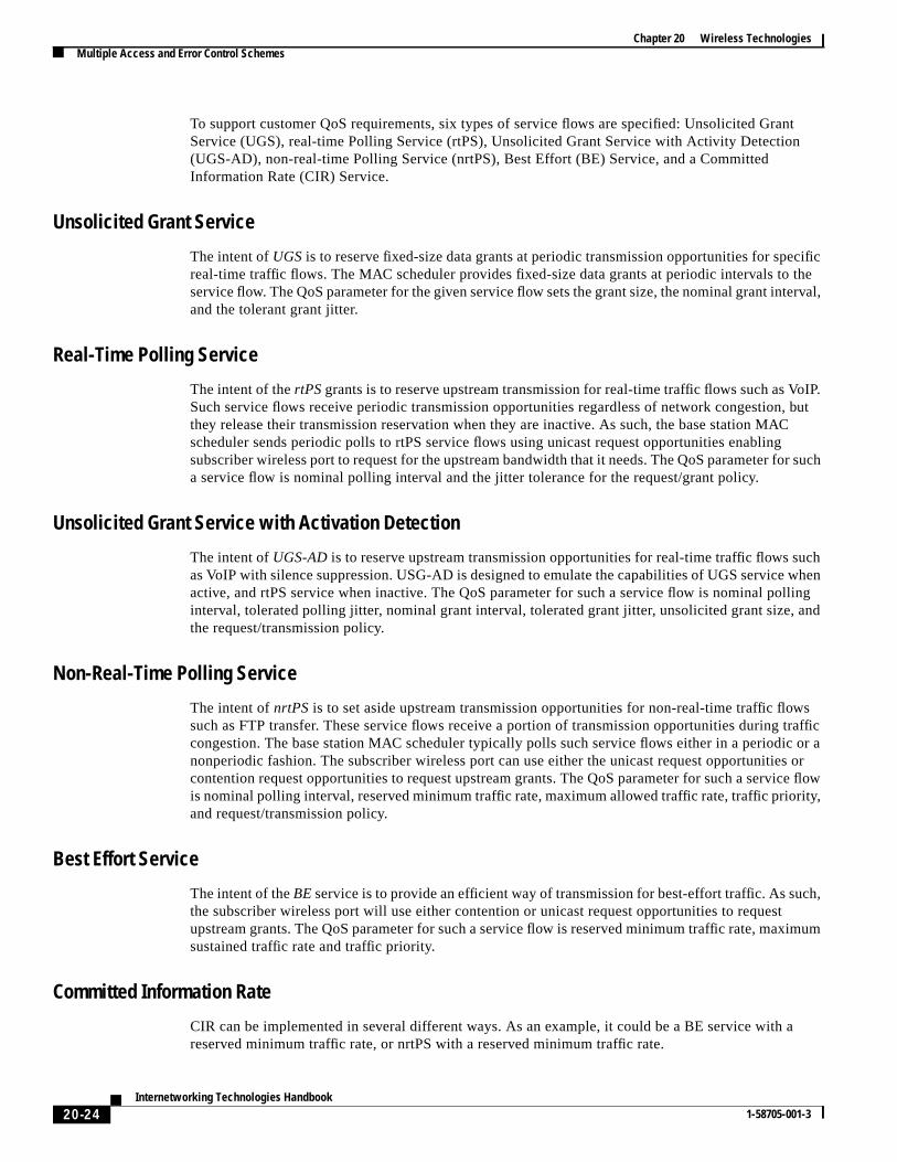
To support customer QoS requirements, six types of service flows are specified: Unsolicited GraService (UGS), real-time Polling Service (rtPS), Unsolicited Grant Service with Activity Detection(UGS-AD), non-real-time Polling Service (nrtPS), Best Effort (BE) Service, and a CommittedInformation Rate (CIR) Service.
Unsolicited Grant Service
The intent ofUGSis to reserve fixed-size data grants at periodic transmission opportunities for spereal-time traffic flows. The MAC scheduler provides fixed-size data grants at periodic intervals to service flow. The QoS parameter for the given service flow sets the grant size, the nominal grant inteand the tolerant grant jitter.
Real-Time Polling Service
The intent of thertPSgrants is to reserve upstream transmission for real-time traffic flows such as VoSuch service flows receive periodic transmission opportunities regardless of network congestionthey release their transmission reservation when they are inactive. As such, the base station MAscheduler sends periodic polls to rtPS service flows using unicast request opportunities enablingsubscriber wireless port to request for the upstream bandwidth that it needs. The QoS parameter foa service flow is nominal polling interval and the jitter tolerance for the request/grant policy.
Unsolicited Grant Service with Activation Detection
The intent ofUGS-ADis to reserve upstream transmission opportunities for real-time traffic flows suas VoIP with silence suppression. USG-AD is designed to emulate the capabilities of UGS serviceactive, and rtPS service when inactive. The QoS parameter for such a service flow is nominal pointerval, tolerated polling jitter, nominal grant interval, tolerated grant jitter, unsolicited grant size,the request/transmission policy.
Non-Real-Time Polling Service
The intent ofnrtPS is to set aside upstream transmission opportunities for non-real-time traffic flowsuch as FTP transfer. These service flows receive a portion of transmission opportunities during congestion. The base station MAC scheduler typically polls such service flows either in a periodicnonperiodic fashion. The subscriber wireless port can use either the unicast request opportunitiecontention request opportunities to request upstream grants. The QoS parameter for such a servicis nominal polling interval, reserved minimum traffic rate, maximum allowed traffic rate, traffic prioriand request/transmission policy.
Best Effort Service
The intent of theBEservice is to provide an efficient way of transmission for best-effort traffic. As sucthe subscriber wireless port will use either contention or unicast request opportunities to requestupstream grants. The QoS parameter for such a service flow is reserved minimum traffic rate, maxsustained traffic rate and traffic priority.
Committed Information Rate
CIR can be implemented in several different ways. As an example, it could be a BE service with reserved minimum traffic rate, or nrtPS with a reserved minimum traffic rate.
20-24Internetworking Technologies Handbook
1-58705-001-3

Chapter 20 Wireless TechnologiesMultiple Access and Error Control Schemes
cast,kets
nit ofdata
ages,ssageAP
islot isused
can
ingginsing
plestureset.
will localckedzero
thescribertion to
of the
gingt the
tion.
tting.layer
Frame and Slot FormatThe frame and slot format is based on the MAC protocol. The downstream transmission is broadsimilar to Ethernet, with no association with framing or a minislot. The recipients of downstream pacperform packet filtering based on the Layer 2 address—the Ethernet MAC or SID value.
The upstream transmission is based on a time-division multiple access (TDMA) scheme, and the utime is a minislot. The minislot size varies based on upstream configuration settings and can carrybetween 8 bytes and approximately 230 bytes. TDMA synchronization is done by time-stamp messand the time of transmission is communicated to each subscriber by the MAP messages (a MAP mecarries the schedule information (map) for each minislot of the next data protocol data unit (PDU)). Mmessages are initiated by the MAC scheduler in the base station and thus convey how each minused (reserved for user traffic, for initial invitation, or as contention slots). The contention slots arefor best-effort traffic to request bandwidth from the scheduler. The frame time is programmable andbe optimized for a given network.
Synchronization Technique (Frame and Slot)Accurately receiving an orthogonal frequency-division multiplexing (OFDM) burst requires burst timand frequency offset estimation. Burst timing means determining where in time the OFDM burst beand ends. Determining the difference between the local demodulating oscillator and the modulatoscillator at the transmitter is called frequency synchronization, or frequency offset estimation.
Burst timing and frequency offset are determined simultaneously through the use of theextra-cyclic-prefix samples in every downstream OFDM burst. Regardless of the channel, the samin the extra-cyclic-prefix will be equal to a set of time-domain samples in the OFDM burst. This strucis optimally exploited to simultaneously identify the correct OFDM burst timing and frequency offThese estimates are then filtered over successive OFDM bursts.
Burst timing and frequency synchronization are required for the downstream link. The upstream linkbe frequency locked once the subscriber unit frequency locks the downstream signal. That is, theoscillator at the subscriber unit is synchronized to the base station oscillator by use of a frequency-loloop. In this way, the upstream transmission that arrives at the base station receiver will have nearlyfrequency offset.
As in any TDMA upstream, each subscriber unit must lock to the TDMA slot when transmitting onupstream. This is referred to as ranging each subscriber. As prescribed by the MAC layer, a subfills periodic ranging slots with a known sequence. This known sequence is used at the base stadetermine proper slot timing.
The upstream TDMA synchronization is done via time-stamp messages that carry the exact timingbase station clock. Each subscriber phase locks its local clock to the base station clock and thensynchronizes its minislot (unit of TDMA) counter to match that of the base station. Furthermore, ranis performed as part of initial acquisition to advance the transmission time of the subscriber so thaprecise arrival of its transmission is synchronized with the expected minislot time of the base sta
Average Overall Delay over LinkThe average overall delay in the link depends on the particular bandwidth and spectral efficiency seIn all cases, the physical layer delay is limited to 5 ms in the downstream. The upstream physicaldelay is less than 2 ms.
20-25Internetworking Technologies Handbook
1-58705-001-3

Chapter 20 Wireless TechnologiesMultiple Access and Error Control Schemes
stem
) andz can
level.
ay be
User
riberal
workvicessesivation
istrarroms.
CPEs.berAS
n tosto be
Power ControlPower control is done in real time to track rapidly changing environment. It is one facet of the sycapability to adjust on a packet-by-packet basis.
The power control is capable of adjusting for fades as deep as 20 dB.
Receiver signal power at the subscriber is controlled through the use of anAutomatic Gain Control(AGC)system. The AGC system measures received power at the analog-to-digital converter (ADCadaptively adjusts the analog attenuation. With AGC, channel gain variations on the order of 200 Hbe accommodated without impacting the OFDM signal processing.
Receive power at the base station is regulated through the use of anAutomatic Level Control (ALC)system. This system measures power levels of each subscriber and creates transmit attenuatoradjustments at the subscriber so that future communication is done with the correct transmit powerThis power control loop is implemented in the physical layer hardware so as not to impact theMAC-layer performance.
Power measurements for the purposes of ALC occur on upstream traffic. Specific power bursts mrequested by the base station MAC to power control subscribers.
Admission ControlA new user is admitted to the system by means of a software suite. Components of this suite areRegistrar, Network Registrar, Modem Registrar, and Access Registrar.
User Registrar enables wireless network subscribers to self-provision via a web interface. Subscself-provisioning includes account registration and activation of the subscriber’s CPE and personcomputers over the wireless access network. User Registrar activates subscriber devices withaccount-appropriate privileges through updates to an LDAPv3 directory.
Network Registrar supplies DHCP and DNS services for the CPEs and personal computers. NetRegistrar DHCP allocates IP addresses and configuration parameters to clients based on per-depolicies, which are obtained from an LDAP directory. Network Registrar allocates limited IP addreand default configuration parameters to inactivated devices, to steer users to the User Registrar actpage.
Modem Registrar adds TFTP and time services to Network Registrar for the CPEs. The Modem RegTFTP builds DOCSIS configuration files for clients based on per-CPE policies, which are obtained fan LDAP directory. Modem Registrar builds limited-privilege configuration files to inactivated CPE
Access Registrar supplies RADIUS services for the CPEs and the clients that are connected to theAccess Registrar RADIUS returns configuration parameters to NAS clients based on per-subscripolicies, which are obtained from an LDAP directory. Access Registrar returns limited-privilege Nand PPP parameters to unregistered subscribers and to inactivated CPEs.
Requirement to Cell RadiusAs stated previously, the system employs frequency-division duplexing (FDD). Unlike time-divisiomultiplexing (TDD) systems, the equipment is not subject to cell radius limits. The only limitationcell radius is that imposed by free space attenuation (FSA) of the radio signals. Timing limitationimposed by the MAC protocol on upstream and downstream channels would permit the cell radiusbeyond the radio horizon (FSA notwithstanding).
20-26Internetworking Technologies Handbook
1-58705-001-3
Chapter 20 Wireless TechnologiesMultiple Access and Error Control Schemes
causeand.
ll-cellhreegonalatedlinged tos.
pportsover
; that
inks,euse
overf more
ratios
tiondual
Unless the subscriber density is very low, as in rural areas, very large cells are not recommended bethey may quickly become capacity-limited and are difficult to scale to meet the higher capacity dem
Requirement for Frequency ReuseTwo architectures are described in this section. The first is a multicellular architecture, called thesmall-cell pattern. The second architecture is known as a single-cell architecture. The baseline smaarchitecture employs a 4× 3 frequency reuse pattern. This means that a four-cell reuse pattern and tsectors are employed within each cell or base station (BS). Within a cellularized network, a hexacell is tiled out to completely cover the service area. In our system, a four-cell tiling pattern is repeover the service area. This tiling pattern puts a lower limit on the reuse distance, thereby controlinterference levels. Employing three sectors within each BS further reduces interference comparomnidirectional antennae. A 4× 3 reuse pattern works well for operations using obstructed (OBS) linkIt uses a total of 24 channels: 12 channels downstream, plus 12 channels upstream.
Note that the number of MMDS channels used may be different than 12 + 12 because the system suchannels narrower than 6 MHz. At any given BS, signals are received from subscriber units (SUs)both OBS links and line-of-sight (LOS) links. In general, OBS links are attenuated at 40 dB/decadeis, R-4 path loss. LOS links, however, propagate based on R-2 path loss. Thus, if an SU has a LOS linkto its BS, it likely also has a LOS link to a reuse BS. To suppress cochannel interference from LOS lhorizontal and vertical polarization are alternatively used on reuse cells. This results in an overall rscheme of 4× 3 × 2 and (still) using a total of 24 channels. This reuse pattern can be continued to cas large a geographical area as desired. Improved frequency reuse can occur when networks are olimited extent. This is because there are fewer tiers of interfering cells. In these cases, greater C/Iare obtained, along with greater network capacity (given a fixed amount of spectrum).
Our approach to frequency reuse for OBS links is conservative in that it does not rely on polarizadiscrimination. Signals transmitted over multipath channels often experience depolarization. If a polarization reuse scheme were employed, it may be very difficult to achieve 99.99 percent linkavailability because as a reuse (undesired) channel is depolarized, it results in higher levels ofinterference to the cochannel (desired) signal.
Radio Resource ManagementRadio resource management falls under the following broad categories:
• Spectrum management in a cell
• Load balancing of CPEs within an upstream channel
• Time-slotted upstream architecture
• Contention resolution
• Traffic policing
• Traffic shaping
• Quality of service controls
20-27Internetworking Technologies Handbook
1-58705-001-3

Chapter 20 Wireless TechnologiesMultiple Access and Error Control Schemes
nelsistscoat
fourCPEsE
be done
on atheticatedaring ofot, thehe CPE.
usedstream
slotsigenttention
time,hannel. two
Spectrum Management in a Cell
Within a cell, the upstream frequency band can be split into as many as four channels. The chanbandwidths that can be configured are 1.5 MHz, 3 MHz, and 6 MHz. The downstream frequency conof one channel that again can be configured as one of 1.5, 3, or 6 MHz. The capability of the Ciswireless products to operate in these wide ranges of channel bandwidths allows the operator greflexibility in designing the network for efficient usage.
Load Balancing of CPEs Within an Upstream Channel
A cell within the Cisco wireless access architecture consists of a downstream channel with up toupstream 1.5-MHz channels. By default, load balancing is performed on the upstream channels asenter the network. Special algorithms run on CPE and the head end to ensure a uniformity of CPloading on the upstream channels. This allocation of CPEs across the upstream channels can alsounder user control.
Time-Slotted Upstream
Cisco’s wireless access solution uses a MAC protocol based on DOCSIS. This protocol is basedbroadcast downstream architecture and a time-slotted upstream architecture. The time slots for upstream govern the access rights of each CPE on to the upstream channel. There is a very sophisscheduler that runs on the head end and allocates these time slots to all the CPEs. Resource shthe upstream bandwidth is realized by each CPE making its request to send in a contention time slhead end responding to it in a subsequent message downstream (called a MAP message), and tusing the information in the MAP message to send the data in an appropriate time slot upstream
Contention Resolution
The DOCSIS protocol uses the notion of contention time slots in the upstream. These time slots areby the CPEs to send a request to the head end for a time slot grant to send data. In a loaded upnetwork, it is possible for these contention slots to become very congested themselves andnonproductive. Cisco’s wireless head end uses an intelligent algorithm to ensure that the contentionare evenly spaced, especially in times of high upstream load. The CPEs also implement an intellalgorithm that ensures that the request grants from the CPEs are spaced evenly over all the conslots in a given MAP message.
Traffic Policing
One of the most important features of the wireless access channel is its shared nature. At any givenseveral hundreds or thousands of CPE subscribers may be sharing an upstream or downstream cAlthough this shared nature is useful for reducing the per-subscriber investment for the operator,important aspects must be considered while providing this access service:
• The need to allocate this bandwidth fairly among all the users
• The need to prevent misbehaving users from completely monopolizing the access
The Cisco solution uses sophisticated algorithms at the head end to police the traffic from eachsubscriber CPE.
20-28Internetworking Technologies Handbook
1-58705-001-3
Chapter 20 Wireless TechnologiesMultiple Access and Error Control Schemes
s thes, andpolicedlayed,beless
ay for
r to
ing
Se
Traffic Shaping
The traffic from each CPE can also be shaped by algorithms running at the head end. This allowoperator to provision services to the CPE based on the critical nature of the traffic, customer needso on. The peak rates of traffic from each subscriber are measured on a continuous basis and areat every request from the CPE. If the request from the CPE exceeds its allotted rate, the grant is dethereby effectively controlling the rate of data transfer from the CPE. Differentiated services can offered to subscribers. The operator can configure different maximum data rates for different wiresubscribers and can charge accordingly. Subscribers requiring higher peak rates and willing to pthe same can be configured with a higher peak rate limit dynamically or statically.
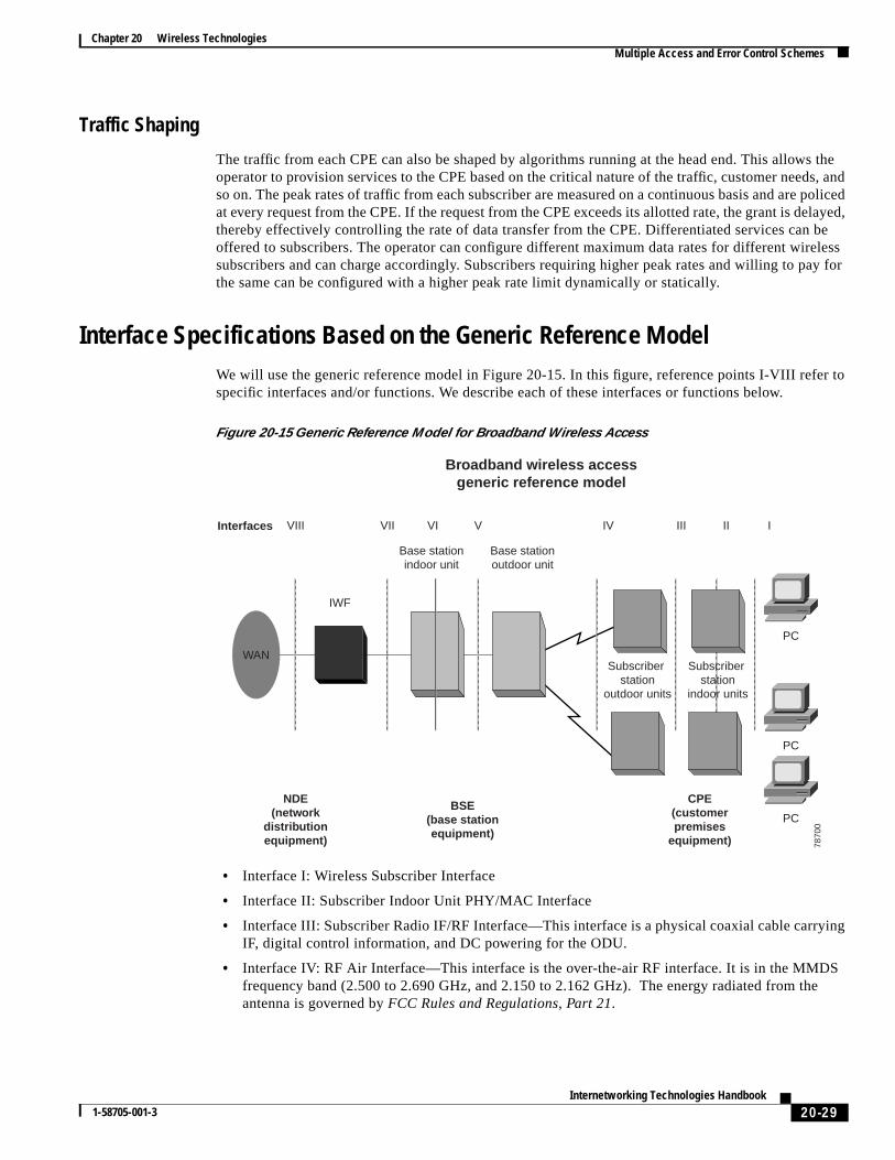
Interface Specifications Based on the Generic Reference ModelWe will use the generic reference model in Figure 20-15. In this figure, reference points I-VIII refespecific interfaces and/or functions. We describe each of these interfaces or functions below.
Figure 20-15 Generic Reference Model for Broadband Wireless Access
• Interface I: Wireless Subscriber Interface
• Interface II: Subscriber Indoor Unit PHY/MAC Interface
• Interface III: Subscriber Radio IF/RF Interface—This interface is a physical coaxial cable carryIF, digital control information, and DC powering for the ODU.
• Interface IV: RF Air Interface—This interface is the over-the-air RF interface. It is in the MMDfrequency band (2.500 to 2.690 GHz, and 2.150 to 2.162 GHz). The energy radiated from thantenna is governed byFCC Rules and Regulations, Part 21.
Interfaces
Broadband wireless accessgeneric reference model
VIII VII VI V IV III II I
WAN
IWF
Base stationindoor unit
Base stationoutdoor unit
NDE(network
distributionequipment)
BSE(base stationequipment)
CPE(customerpremises
equipment)
Subscriber station
outdoor units
Subscriber station
indoor units
PC
PC
PC78
700
20-29Internetworking Technologies Handbook
1-58705-001-3

Chapter 20 Wireless TechnologiesMultiple Access and Error Control Schemes
Suchve
xiale
scribertreamll this
uter);r endms canmitertain
s and
shownnedtocol
imit
h the
ths
nd andfilterill not
ment
bearer base
are
d
The above descriptions of interfaces I to III represent Cisco Systems products by way of example.products will interwork with the base station described next, via interface IV compatibility, but will hamany new and different CPE interfaces, features, and services.
• Interface V: Base Station RF/IF Interface—This interface at the base station is a physical coacable carrying intermediate frequency (IF), digital control information, and DC powering for thoutdoor unit (ODU).
• Interface VI: Base Station Indoor PHY/MAC Interface—This interface is internal to the Ciscorouter.
• Interface VII: Network Connection Interface
Wireless Protocol Stack
The access wireless architecture consists of a base station system that serves a community of subsystems. It is a point-to-multipoint architecture in the sense that the entire bandwidth on the upsand downstream is shared among all the subscribers. The protocol stack implemented to make awork is based on the DOCSIS standards developed by the Cable Labs consortium.
The current state of the art is the version by Cisco that includes a base station end (a UBR7200 rothe subscriber end is in the 3600 or a 900 router series. The base station end and the subscribeoperate as forwarding agents and also as end systems (hosts). As forwarding agents, these systealso operate in bridging or routing mode. The principal function of the wireless system is to transInternet Protocol (IP) packets transparently between the base station and the subscriber location. Cmanagement functions also ride on IP that include, for example, spectrum management functionthe software downloading.
Both the subscriber end and the base station end of the wireless link are IP hosts on a network, asin Figure 20-16, and they fully support standard IP and Logical Link Control (LLC) protocols, as defiby the IEEE 802 LAN/MAN Standards Committee standards. The IP and Address Resolution Pro(ARP) protocols are supported over DIX and SNAP link layer framing. The minimum link layerminimum transmission unit (MTU) on transmit from the base station is 64 bytes; there is no such lfor the subscriber end. IEEE 802.2 support for TEST and XID messages is provided.
The primary function of the wireless system is to forward packets. As such, data forwarding througbase station consists of transparent bridging or network layer forwarding such as routing and IPswitching. Data forwarding through the subscriber system is link layer transparent bridging as wiLayer 3 routing based on IP. Forwarding rules are similar to [ISO/IEC10038], with modifications adescribed in DOCSIS specifications Section 3.1.2.2 and Section 3.1.2.3. Both the base station ethe subscriber end support DOCSIS-modified spanning-tree protocols and include the capability to802.1d bridge PDUs (BPDUs). The DOCSIS specification also assumes that the subscriber units wbe connected in a configuration that would create network loops.
Both the base station end and the subscriber end provide full support for Internet Group ManageProtocol (IGMP) multicasting.
Above the network layer, the subscribers or end users can use the transparent IP capability as afor higher-layer services. Use of these services will be transparent to the subscriber end and thestation end.
In addition to the transport of user data, several network management and operation capabilitiessupported by the base station end and the subscriber end:
• Simple Network Management Protocol (SNMP), [RFC-1157], for network management
• Trivial File Transfer Protocol (TFTP), [RFC-1350], a file transfer protocol, for downloadingsoftware and configuration information, as modified by RFC 2349, “TFTP Timeout Interval anTransfer Size Options” [RFC-2349]
20-30Internetworking Technologies Handbook
1-58705-001-3

Chapter 20 Wireless TechnologiesSystem Performance Metrics
ion
ens.
s are
• Dynamic Host Configuration Protocol (DHCP), [RFC-2131], a framework for passing configuratinformation to hosts on a TCP/IP network
• Time of Day Protocol [RFC-868], to obtain the time of day
Figure 20-16 Wireless Protocol Stack for Network Management and Operation
Link layer security is provided in accordance with DOCSIS baseline privacy specifications.
System Performance MetricsTable 20-4 shows the network capacity for High Capacity Suburban/Urban Small-Cell Network.
These capacities are based on 6-MHz downstream channels and 3-MHz upstream channels:
• Downstream—6 MHz; at the medium VOFDM-throughput setting, 17.0 Mbps.
• Upstream—3.0 MHz; at the low VOFDM-throughput setting, 4.4 Mbps. The low setting has bechosen so that both SB and residential SUs may be serviced by the same upstream channel
This high-capacity network has 83 cells in the network, each with 3 sectors. A total of 249 sectorin the network, each serving 21 SB and 510 HH. Overall, a total of 249× 21, or 5,229, SBs are servedby the network; similarly, a total of 126,990 HHs are served.
This network design graphically illustrates the power and scalability of Cisco’s technology.
IP
Datalink
layer
LLC
MAC security
MAC
Wireless TC
Forwarding
PHY layer Wireless PMD
IP
Bridging Datalink
layer
PHY layer
LLC
MAC security
MAC
Wireless TC
Wireless PMD
To network Wireless media To CPE 7870
1
Table 20-4 Network Capacity for High-Capacity Suburban/Urban Small-Cell Network
Cell Radius(Mile)
No. ofCells
SmallBusinessesServed
SmallBusinessPenetration
HouseholdsServed
HouseholdPenetration
2.2 83 5,229 10.5% 126,990 15.9%
20-31Internetworking Technologies Handbook
1-58705-001-3
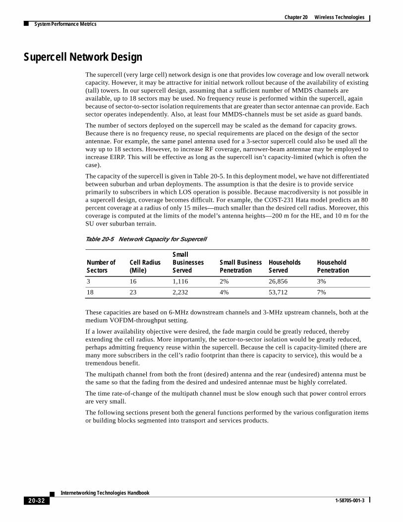
Chapter 20 Wireless TechnologiesSystem Performance Metrics
working
gaine. Eachands.
ws.ctor
d all theyed to the
iatede
ble in an 80r, thisr the
at the
d,re aree a
ust be
rrors
tems
Supercell Network DesignThe supercell (very large cell) network design is one that provides low coverage and low overall netcapacity. However, it may be attractive for initial network rollout because of the availability of exist(tall) towers. In our supercell design, assuming that a sufficient number of MMDS channels areavailable, up to 18 sectors may be used. No frequency reuse is performed within the supercell, abecause of sector-to-sector isolation requirements that are greater than sector antennae can providsector operates independently. Also, at least four MMDS-channels must be set aside as guard b
The number of sectors deployed on the supercell may be scaled as the demand for capacity groBecause there is no frequency reuse, no special requirements are placed on the design of the seantennae. For example, the same panel antenna used for a 3-sector supercell could also be useway up to 18 sectors. However, to increase RF coverage, narrower-beam antennae may be emploincrease EIRP. This will be effective as long as the supercell isn’t capacity-limited (which is oftencase).
The capacity of the supercell is given in Table 20-5. In this deployment model, we have not differentbetween suburban and urban deployments. The assumption is that the desire is to provide servicprimarily to subscribers in which LOS operation is possible. Because macrodiversity is not possia supercell design, coverage becomes difficult. For example, the COST-231 Hata model predictspercent coverage at a radius of only 15 miles—much smaller than the desired cell radius. Moreovecoverage is computed at the limits of the model’s antenna heights—200 m for the HE, and 10 m foSU over suburban terrain.
These capacities are based on 6-MHz downstream channels and 3-MHz upstream channels, bothmedium VOFDM-throughput setting.
If a lower availability objective were desired, the fade margin could be greatly reduced, therebyextending the cell radius. More importantly, the sector-to-sector isolation would be greatly reduceperhaps admitting frequency reuse within the supercell. Because the cell is capacity-limited (themany more subscribers in the cell’s radio footprint than there is capacity to service), this would btremendous benefit.
The multipath channel from both the front (desired) antenna and the rear (undesired) antenna mthe same so that the fading from the desired and undesired antennae must be highly correlated.
The time rate-of-change of the multipath channel must be slow enough such that power control eare very small.
The following sections present both the general functions performed by the various configuration ior building blocks segmented into transport and services products.
Table 20-5 Network Capacity for Supercell
Number ofSectors
Cell Radius(Mile)
SmallBusinessesServed
Small BusinessPenetration
HouseholdsServed
HouseholdPenetration
3 16 1,116 2% 26,856 3%
18 23 2,232 4% 53,712 7%
20-32Internetworking Technologies Handbook
1-58705-001-3

Chapter 20 Wireless TechnologiesSystem Performance Metrics
f IF
tionsories,
as the
it,ation
rated theeunit
cursr the
e ofy to. Thetended
Transport Layer ProductsThe transport layer is composed of the equipment that provides the transmission and reception osignals between the rooftop and router equipment and the RF signals over the air. The transportequipment is designed to work in an outdoor environment mounted on buildings or telecommunicatowers. The P2MP transport layer is physically segmented into hub and terminal equipment categas depicted in Figure 20-17.
Figure 20-17 Hub Site Equipment (Per Sector)
P2MP Transport Equipment Element—Customer PremisesThe terminal equipment consists of an integrated RF transceiver/antenna, commonly referred to rooftop unit (RTU). This equipment is easily installed on any customer rooftop using a standardmounting device. The RTU requires two RG-11 coaxial cables to the indoor equipment for transmreceive, and power. The RTU operates on 12.5VDC (nominal) at the input and in standard configurmust be installed within 60 m of the network interface unit (NIU), although longer spans can beengineered and supported.
Rooftop UnitThe sole element of the P2MP transport layer at the terminal site is the RTU. The RTU is an integantenna and RF transceiver unit that provides wireless transmission and reception capabilities in5.7 GHz frequency region. Received and transmitted signals are frequency translated between th5.7 GHz region and an intermediate frequency (IF) in the 400 MHz range to the network interface(NIU).
The RTU consists of an antenna(s), a down-converter/IF strip, and an up-converter/transmitter. Itreceives/transmits using orthogonal polarization. Selection of polarization (horizontal/vertical) ocat installation and is dictated by the hub-sector transmitter/receiver. This selection remains fixed foduration that service is provided to that site.
The RTU mounts on the exterior of a subscriber’s building. Some alignment is required to gain linsight (LOS) to the hub serving the RTU. Multiple RTUs can be deployed to provide path redundancalternate hub sites. The RTU requires dual coax cable (RG-11) runs to the NIU for signal and powermaximum standard separation between the RTU and the NIU is 60 m. This separation can be exvia application-specific designs.
Power source
MultiplexerAggregator or
switch
Channelgroup(s)
Hub site equipment (per sector)
Transmitmodule(s)
Receivemodule(s)
SRIU
RTU NIU
Customer site equipment
7870
2
20-33Internetworking Technologies Handbook
1-58705-001-3

Chapter 20 Wireless TechnologiesWLAN Standards Comparison
ceiveivedte
se ofeasic
. Allndardtingtime
s thatrten the
ctency,
orr allrally
e, and
Basic ReceiverA single basic receiver is required per 90˚ sector, if no return-path redundancy is required. The remodule is an integrated 5.7-GHz receiver/down-converter/antenna. A collection of signals is recefrom customer units operating in the 5.7 GHz band and is block down-converted to an intermediafrequency signal. This signal is provided to any of the channel group types. Vertical or horizontalpolarization is selectable, and a redundant receiver per sector can be deployed as an option.
High-Gain ReceiverA high-gain receiver is used in lieu of the basic receiver when higher link margin is required becauthe specific geographic conditions of deployment. The high-gain receive module is intended to bmatched only with the high-gain transmit module. The specifications are identical to those of the breceive module, except for physical package and antenna gain.
Because of the modularity of the SP2200 products, there is no one standard rack or set of racksSP2200 elements are designed to mount in a standard 19-inch (48.3-cm) open relay rack with a staEIA hole pattern or an equipment enclosure with 19 inches (48.3 cm) of horizontal equipment mounspace. Final assembly of the equipment into racks is accomplished on site at initial install or overas capacity demands.
LMDS Environmental ConsiderationsEnvironmental conditions such as rain and smog must be considered when deploying RF systemtransmit at frequencies above 10 GHz because these conditions degrade the signal path and shomaximum range for a given data link.
LMDS data links are generally about one-fourth that of MMDS or U-NIII links and require fairly striadherence to a line-of-sight implementation. One of the more favorable aspects of the LMDS frequhowever, is that it has exceptional frequency reuse capabilities.
Data link availability is expressed in terms of the number of nines that follow the decimal point. Fexample, 99.999 percent link availability means that a data link will be up and online (available) fobut .001 percent of the year. Link availability is dependent on a wide range of items, but these genebegin with fundamental RF system design issues such as antenna size, range between antennaatmospheric conditions (for LMDS band).
WLAN Standards ComparisonTable 20-6 provides a brief comparison of WLAN standards.
Table 20-6 A Brief Comparison of HomeRF, Bluetooth, and 802.11 WLAN Standards
HomeRF Bluetooth 802.11
Physical Layer FHSS1 FHSS FHSS, DSSS2, IR3
Hop Frequency 50 hops per second 1600 hops per second 2.5 hops per second
Transmitting Power 100 mW 100 mW 1W
Data Rates 1 or 2 Mbps 1 Mbps 11 Mbps
20-34Internetworking Technologies Handbook
1-58705-001-3

Chapter 20 Wireless TechnologiesSummary
for
uropehip
. Thepecific
uter,
jority
stant:
:
The following should be noted in Table 20-6:
• 40- to 128-bit RC4 refers to very robust data security algorithms.
• An 802.11 range of 1,000 feet refers to outdoor conditions. Indoor conditions are more difficultthese types of RF systems.
• 802.11 power output of 1W is substantial.
• The maximum number of devices supported depends on data rate per device.
• The Aironet acquisition uses 802.11.
Although there are three standards in use in the United States, and an additional two are in use in E(HyperLAN and HyperLAN2), the FCC thinks highly of the 802.11b standard, and a close relationsexists between the FCC and the IEEE, which backs the standard.
SummaryAt least 18 different types of wireless are in commercial use today. Therefore, as this technologybecomes more mainstream, users will need to be increasingly specific in their reference to the termdifferent types of wireless are quite unique to each other on numerous levels, and they require stypes of expertise to deploy, use, and maintain.
In its state-of-the-art deployment, a wireless link emulates all the capabilities of a fully featured rowhich means that a wireless link can provide VPN, enterprise toll bypass, and MDU/MTU accessservices. This is one of the primary differences between a Layer 2 product as provided by the maof wireless vendors and the Layer 3 solution provided by Cisco Systems.
Regardless of the provider of a wireless system, the fundamental elements remain relatively con
• Data or network
• Edge or access router
• DSP medium
• RF medium (coax, modulator/demodulator, antenna)
• RF management software
Like every access medium or technology, wireless has its pros and cons. The pros include these
• It’s much less expensive to deploy than trenching for cabling.
• It’s much quicker to deploy—a link can be up in a couple of hours.
Max # Devices Up to 127 Up to 26 Up to 26
Security Blowfish format 0-, 40-, and 64-bit 40- to 128-bit RC4
Range 150 feet 30 to 300 feet 400 feet indoors,1000 feet LOS
Current Version V1.0 V1.0 V1.0
1. FHSS–frequency hopping spread spectrum
2. DSSS–direct sequence spread spectrum
3. IR–infrared
Table 20-6 A Brief Comparison of HomeRF, Bluetooth, and 802.11 WLAN Standards (continued)
HomeRF Bluetooth 802.11
20-35Internetworking Technologies Handbook
1-58705-001-3

Chapter 20 Wireless TechnologiesReview Questions
nnae
lator,
loys or
ree ofn’t
’s
• Wireless can go where cables can’t, such as mountainous or inaccessible terrain.
• Less red tape is involved for deployment, if roof rights or elevation access is available.
• It involves an inherent high degree of security, and additional security layers can be added.
• Wireless provides broadband mobility, portability that tethered access doesn’t provide.
Review QuestionsQ—What is the primary difference between narrowband and broadband wireless?
A—Broadband wireless offers bandwidth in excess of 1.5 Mbps.
Q—What is the primary difference between WLAN and fixed wireless?
A—WLAN enables the user mobility up to pedestrian speeds. Fixed wireless requires that both anteremain stable and fixed in their positions.
Q—Identify three different applications for wireless.
A—LAN, backhaul, toll bypass, and VPNs.
Q—What are the fundamental hardware elements of a wireless solution?
A—Data or network, edge or access router, DSP medium, RF medium (coax, modulator/demoduantenna).
Q—What are the primary benefits of wireless?
A—Wireless is much less expensive to deploy than trenching for cabling; is much quicker to depbecause a link can be up in a couple of hours; can go where cables can’t, such as in mountainouinaccessible terrain; involves less red tape for deployment; and comes with an inherent high degsecurity. In addition, wireless provides broadband mobility—portability that tethered access doesprovide.
For More Information• http://winwww.rutgers.edu/pub/Links.html (Wireless links)
• http://home.earthlink.net/~aareiter/introto.htm (Guide to wireless Internet)
• http://www.airlinx.com/products.htm (RF product menu)
• http://www.allnetdevices.com/news/index.html (allNetDevices news)
• http://www.americasnetwork.com/issues/97issues/971001/100197_futurebb.html (Broadbandevolution)
• http://www.broadbandforum.com (Cable Broadband Forum)
• http://www.businesswire.com/cnn/wcii.htm (WinStar press releases)
• http://www.comet.columbia.edu/~angin/e6950/coolsites.html (Wireless topics home page)
• http://www.ctimag.com/ (CTI newsletter)
• http://www.data.com/tutorials/web_connection.html (Wireless web tutorial)
• http://www.dectweb.com/sitemap.htm (DECTweb)
• http://www.dnspublishing.com/rc/rcindex.cfm (Reciprocal Compensation site)
• http://www.ericsson.com/BN/dect2.html (Ericsson DECT)
20-36Internetworking Technologies Handbook
1-58705-001-3

Chapter 20 Wireless TechnologiesFor More Information
rier
urse
h)
D
• http://www.fcc.gov/Bureaus/Common_Carrier/Reports/FCC-State_Link/recent.html (FCC cardata)
• http://www.fiberopticsonline.com (Fiberoptics Online)
• http://www.gbmarks.com/wireless.htm (Goodman’s Wireless Telecomm links)
• http://www.globalwirelessnews.com/ (RCR Global Wireless news)
• http://www.herring.com/mag/issue48/comm.html (Ericsson’s broadband plans)
• http://www.hometoys.com/htinews/oct99/articles/allied/allied.htm
• http://http.cs.berkeley.edu/~gribble/cs294-7_wireless/summaries/index.html (UC Berkeley coin wireless)
• http://www.internettelephony.com (Internet telephony)
• http://www.internettelephony.com/archive/featurearchive/7.06.98.html (FSAN overview)
• http://www.it.kth.se/edu/gru/Fingerinfo/telesys.finger/Mobile.VT96/DECT.html (DECT)
• http://www.itu.int/imt/2-radio-dev/proposals/index.html (ITU world radio standards)
• http://www.mobilecomputing.com/ (Mobile Computing & Communications)
• http://www.phonezone.com/tutorial/nextgen.htm (Next-generation phone systems)
• http://www-star.stanford.edu/~osama/links.html (Single-chip 2.4GHz radio)
• http://www.tek.com/Measurement/App_Notes/ap-Wireless/welcome.html (Wireless digitalmodulation)
• http://www.telecomweb.com/ct/ (Communications Today)
• http://www.ti.com/sc/docs/wireless/cellterm.htm (Glossary of wireless terms)
• http://www.ti.com/sc/data/wireless/panos1.pdf (Wireless systems and technology overview)
• http://www.tiap.org (Guide to evolving wireless services)
• http://www.tr.com/ (Telecommunications Reports)
• http://www.trio.ca/annual/thrusts/mobsat.htm (Ontario, Canada, wireless and mobile researc
• http://www.wapforum.org/what/technical.htm (WAP Forum specs)
• http://www.webproforum.com/wpf_wireless.html (Wireless tutorials)
• http://www.wirelessdata.org (Wireless Data Forum)
• http://www.wirelessdata.org/news/currenttxt.asp (Current newsletter)
• http://www.wirelessdesignonline.com (Wireless Design Online)
• http://www.wirelessweek.com/industry/indtoc.htm (Wireless Week industry information andstatistics)
• http://www.wow-com.com/index.cfm (CTIA wireless web page: World Of Wireless)
• http://www.wow-com.com/wirelesssurvey/1298datasurvey.pdf (1998 U.S. Wireless Survey)
• http://www.zdnet.com/anchordesk/story/story_1384.html (Survey of access technologies by ZAnchordesk)
• http://www.zdnet.com/intweek/print/971013/158897.html (October 1997 survey of accesstechnologies)
Regulation and Government
• http://www.broadband-guide.com/lw/reg/index.html (Pennwell pubs)
20-37Internetworking Technologies Handbook
1-58705-001-3

Chapter 20 Wireless TechnologiesFor More Information
)
n
ne
• http://www.commnow.com/3rd_Generation.html (Article about TR-45 workshop on IMT-2000
• http://www.fcc.gov/bandwidth/ (FCC bandwidth home page)
• http://www.itu.ch/imt/ (International Mobile Telecommunications–2000 [ITU R/T Initiative])
• http://www.ntia.doc.gov/osmhome/allochrt.html (U.S. Spectrum chart)
WLL
• http://www.analysys.co.uk/publish/registered/locloop/default.htm#contents (LL competition)
• http://www.globaltelephony.com/archives/GT598/GT598cover.html (WLL cover feature)
• http://www.internettelephony.com/content/html/focus/feature1.html (Feb 1998 Next-generatioWLL)
• http://www.isir.com/wireless/ (WLL world)
• http://www.ntia.doc.gov/forums/wireless/index.html (WLL forum)
• http://www.verticom.com/cieee_1/index.htm (Steve Goldberg’s IEEE talk on Wireless LL)
• http://www.wavespan.com/solutions/ultraman.shtml (Wavespan Stratum 100)
LMDS/MMDS (Wireless Cable)
• http://businesstech.com/telecom/btfreetelecom9902.html (History of MMDS)
• http://grouper.ieee.org/groups/802/16/ (IEEE 802.16 BroadBand Fixed Wireless home page)
• http://nwest.nist.gov/tutorial_ets.pdf (A good LMDS context briefing)
• http://nwest.nist.gov/ (Click on News for current standards activity)
• http://www.americasnetwork.com/issues/98issues/980801/980801_lmds.html
• http://www.americasnetwork.com/issues/99supplements/990601lmds/990601_toc.htm
• http://www.cabledatacomnews.com/wireless/cmic12.html (North American MMDS trials)
• http://www.fcc.gov/Bureaus/Wireless/Factsheets/lmds.html (FCC fact sheet on LMDS auctionresults)
• http://www.nmcfast.com (IBM and NewMedia partner in MMDS)
• http://www.teledotcom.com/1097/features/tdc1097telcos.html (BellSouth MMDS writeup)
• http://www.WCAI.com/index.htm (The WCA’s home page for the Wireless Cable Association)
• http://www.webproforum.com/nortel4/ (Nortel tutorial on LMDS)
• http://www.zdnet.com/intweek/print/970630/inwk0009.html (Broadband wireless alternatives)
Cordless
• http://www.broadband-guide.com/wi/techupdate/techupjf98.html (Wireless in-building telephosystems)
Satellite
• http://sat-nd.com/news/ (Satellite news)
• http://tcpsat.grc.nasa.gov/tcpsat/ (TCP over Satellite WG)
• http://www.data.com/issue/990707/satellite.html (Internet satellite links)
• http://www.ee.surrey.ac.uk/Personal/L.Wood/constellations/ (The orbits)
• http://www.herring.com/mag/issue48/space.html (Loral portrait)
• http://www.iridium.com/index.html (Iridium home page)
20-38Internetworking Technologies Handbook
1-58705-001-3

Chapter 20 Wireless TechnologiesGlossary Terms
s in
r
s a
• http://www.msua.org/mobile.htm (Mobile Satellite Users Association)
• http://www.project77.com Project77 (Iridium pricing)
• http://www.satphone.com/ (Overview of programs)
• http://www.satphone.net (Iridium Service Provider Satellite Warehouse)
• http://www.skybridgesatellite.com/ (SkyBridge)
• http://www.skyreport.com/ (Research and reporting for the satellite industry)
• http://www.spotbeam.com/links.htm (Internet, satellite links)
• http://www.spotbeam.com/mansum.htm (GEO summary)
• http://www.spotbeam.com/mansum99.htm (Internet and ISP summary)
• http://www.techweb.com/se/directlink.cgi?NWC19980315S0017 (Broadband Ka satellites)
• http://www.techweb.com/se/directlink.cgi?NWC19980315S0011 (Satellite insecurity)
• http://www.wizard.net/~vvaughn/sat.htm (Satellite voice system comparisons)
Modulations
• http://diva.eecs.berkeley.edu/~linnartz/MCCDMA.html (OFDM definitions)
• http://propagation.jpl.nasa.gov/propdb/HELP/CLOUD.HTM (Effects of clouds and rain)
• http://sss-mag.com/favlinks/index.html (Many modulation links)
• http://wireless.stanford.edu/research.html (Stanford University wireless research)
• http://www.catv.org/modem/technical/ofdm.html (OFDM, the next upstream modulation)
• http://www.ee.mtu.edu/courses/ee465/groupe/index.html (CDMA class)
• http://www.gr.ssr.upm.es/~ana/ofdm_links.htm (OFDM sites)
• http://www.sm.luth.se/csee/sp/projects/ofdm/ofdm.html (OFDM description)
Interfaces
• http://cx667314-a.chnd1.az.home.com/1394Informer/990800.htm 1394 (News home page)
• http://skipstone.com/compcon.html (IEEE 1394 overview)
• http://www-europe.cisco.com/warp/public/459/8.html (HSSI)
• http://www.mfsdatanet.com/mfs-international/hssi.html (HSSI)
• http://www.sdlcomm.com/ (HSSI PCI module)
Glossary TermsThe following list of terms was selected by their frequency of use when discussing Cisco wirelesinterests. This list should not be considered comprehensive with respect to the wireless industrygeneral. Furthermore, certain aspects of these acronyms remain in a state of flux and should beconsidered accurate per the date of this document.
• adjacent channel—A channel or frequency that is directly above or below a specific channel ofrequency.
• amplitude—The magnitude or strength of a varying waveform. Typically, this is represented acurve along the x-axis of a graph.
20-39Internetworking Technologies Handbook
1-58705-001-3

Chapter 20 Wireless TechnologiesGlossary Terms
ty,in timetrastsumber
forfor a
a
. For
or in
any
hareout ofe datas data setup,
ones
rrierers or
useds.
sedanmple,rule, 20) by a
e order
s ofts of
• analog signal—The representation of information with a continuously variable physical quantisuch as voltage. Because of this constant change of the wave shape as it passes a given pointor space, an analog signal may have a virtually indefinite number of states or values. This conwith a digital signal, which is expressed as a square wave and therefore has a very limited nof discrete states.
• antenna—A device for transmitting or receiving a radio frequency (RF). Antennae are designedspecific and relatively tightly defined frequencies, and are quite varied in design. An antenna2.5 GHz (MMDS) system will not work for a 28 GHz (LMDS) design.
• antenna gain—The measure of an antennaassemblyperformance relative to a theoretical antenncalled an isotropic radiator (radiator is another term forantenna). Certain antenna designs featurehigher performance relative to vectors or frequencies.
• bandwidth—The frequency range necessary to convey a signal measured in units of hertz (Hz)example, voice signals typically require approximately 7 kHz of bandwidth, and data traffictypically requires approximately 50 kHz of bandwidth.
• BTA—Basic trading area; an area or footprint in which an entity is licensed to transmit itsfrequencies. BTAs were established by Rand McNally and are defined as county lines. RandMcNally licensed its mapping data to the FCC for ease of designation for site licenses.
• broadband—In general, an RF system is deemed broadband if it has a constant data rate at excess of 1.5Mbps. Its corresponding opposite is narrowband.
• broadcast—In general, this is the opposite of narrowcast and infers that a signal is sent to mpoints at the same time or is transmitted in an omnidirectional pattern.
• CDMA —Code division multiple access; a transmission scheme that allows multiple users to sthe same RF range of frequencies. In effect, the system divides a small range of frequenciesa larger set and divides the data transmission among them. The transmitting device divides thamong a preselected set of nonsequential frequencies. The receiver then collates the varioupieces from the disparate frequencies into a coherent data stream. As part of the RF systemthe receiver components are advised of the scrambled order of the incoming frequencies. Animportant aspect of this scheme is that the receiver system filters out any signal other than thespecified for a given transmission.
• channel—A communications path wide enough to permit a single RF transmission.
• coax cable—The type of cable used to connect Cisco equipment to antennae.
• converter—RF systems have two fundamental frequencies: that which is sent over the air (cafrequency), and that which is sent back and forth between Cisco equipment and the antenna(intermediate frequency). This is performed by a converter; also known as up or down convertetransverters. The intermediate frequencies are split into a higher and lower frequency that isfor either transmission or reception of data between the antenna assembly and Cisco device
• dB—Decibel; a unit for measuring relative power ratios in terms of gain or loss. Units are expresin terms of the logarithm to base 10 of a ratio and typically are expressed in watts. dB is not absolute value—rather, it is the measure of power loss or gain between two devices. As an exaa –3 dB loss indicates a 50 percent loss in power, a +3 dB reading is a doubling of power. Theof thumb to remember is that 10 dB indicates an increase (or loss) by a factor of 10. LikewisedB indicates an increase (or loss) of a factor of 100, and 30 dB indicates an increase (or lossfactor of 1000.
Because antennae and other RF devices/systems commonly have power gains or losses on thof magnitude of 4, dB is a more easily used expression.
• dBi—dB referenced to an isotropic antenna (hence the “i”) that is theoretically perfect in termsymmetric patterns of radiation. Real-world antennae do not perform with even nominal amounsymmetry, but this effect is generally used to the advantage of the system designer.
20-40Internetworking Technologies Handbook
1-58705-001-3
Chapter 20 Wireless TechnologiesGlossary Terms
of
A, and
anis isain.
thesifiedies
not
reiscoll uses
Thisse.
ists, but
renses
notother
ateses.159Hz,ngeisd
anceite of
• dBm—dB referencing 1 milliwatt; 0 dBm is defined as 1 mW at 1 kHz of frequency at 600 ohmsimpedance.
• dBW—dB referencing 1 watt.
• demodulator—A device for assembling signals after they have been received by an antenna.demodulator is typically the first major device downstream from an antenna receiving systemit exists on the block diagram before various Cisco devices. The corresponding device on thetransmission side of a system is a modulator.
• EIRP—Effective isotropic radiated power; the term for the expression of the performance of antenna in a given direction relative to the performance of a theoretical (isotropic) antenna. Thexpressed in watts or dBW. EIRP is the sum of the power sent to the antenna plus antenna g
• electromagnetic spectrum—The full range of electromagnetic (same as magnetic) frequencies,subset of which is used in commercial RF systems. Commercial RF systems are typically clasin ranges that include MF, HF, VHF, SHF, and EHF. Military systems typically include frequencoutside these types.
• fixed wireless—The type of Cisco wireless in which both the transmitter and the receiver are mobile. Cisco wireless is always broadband wireless, with data rates in excess of 1.5 Mbps.
• footprint —The geographical area in which an entity is licensed to broadcast its signal.
• frequency reuse—One of the fundamental concepts on which commercial wireless systems abased. It involves the partitioning of an RF radiating area (cell) into segments of a cell—for Cpurposes, this means that the cell is broken into three equal segments. One segment of the cea frequency that is far enough away from the frequency in the bordering segment to provideinterference problems. The same frequency is used at least two cells apart from each other. practice enables cellular providers to have many times more customers for a given site licen
• gain—The ratio of the output amplitude of a signal to the input amplitude of a signal. This ratiotypically expressed in decibels. The higher the gain, the better the antenna receives or transmialso the more noise it includes.
• license—The purchased right to transmit RF waves over a BTA is typically given for a ten yeaperiod. The license tightly governs the design parameters of an RF system and its use. RF licare (typically) purchased from the FCC on an auction basis.
The FCC provides licenses to ensure maximum competition in a free market (although this isalways obvious in the way the FCC manages the auctions) and spectral efficiency, which is anway of stating efficient use of the RF spectrum.
• LMDS—Local Multipoint Distribution Service; a relatively low-power license for broadcastingvoice, video, and data. Typically two licenses are granted in three frequencies each to separentities within a BTA. These licenses are known as Block A or Block B licenses. Block A licenoperate from 27.5 to 28.35 GHz, 29.10 to 29.25 GHz, and 31.075 to 31.225 GHz, for a total of 1MHz of bandwidth. Block B licenses operate from 31.00 to 31.075 GHz, and 31.225 to 31.300 Gfor a total of 150 MHz of bandwidth. LMDS systems have a typical maximum transmission raof approximately 3 miles, as opposed to the transmission range of an MMDS system, which typically 25 miles. This difference in range is primarily a function of physics and FCC-allocateoutput power rates.
• LOS—Line of sight; refers to the fact that there must be a clear, unobstructed path betweentransmitters and receivers. This is essential for LMDS products and enhances general performin every RF deployment, compared to partial or completely obstructed data paths. The opposLOS is non-line-of-sight (NLOS).
20-41Internetworking Technologies Handbook
1-58705-001-3

Chapter 20 Wireless TechnologiesGlossary Terms
teeivers..686
hco’s
ose
osstic
here.
and
s lessMDS,
00
,, as
inut, as
and
,that
ble
• MMDS—Multichannel Multipoint Distribution Service; this is comprised of as many as 33 discrechannels that are transmitted in a pseudorandom order between the transmitters and the recThe FCC has allocated two bands of frequencies for each BTA—2.15 to 2.161 GHz, and 2.5 to 2GHz.
• mobile wireless—Cisco does not provide mobile wireless components; instead, it providesbackbone devices such as a GGSN that support mobile wireless infrastructures.
• NLOS—Non-line-of-sight; also known as obstructed path or pathway.
• parabolic antenna—A dishlike antenna that sends RF waves in a highly focused manner. Sucantennae provide very large power gains and are highly efficient. This antenna is typical to CisLMDS, U-NII, and MMDS systems, but this is not the only design available or appropriate for thfrequencies.
• path loss—The power loss that occurs when RF waves are transmitted through the air. This loccurs because the atmosphere provides a filtering effect to the signal. Certain electromagnefrequencies (very high and noncommercial) are completely blocked or filtered by the atmosp
• point-to-multipoint —P2MP; generally infers the communication between a series of receiverstransmitters to a central location. Cisco P2MP is typically set up in three segments to enablefrequency reuse. Cisco offers MMDS, U-NII, and LMDS systems in P2MP.
• Point-to-point—P2P; has a higher bandwidth than P2MP because, among other things, it haoverhead to manage the data paths and only one receiver exists per transmitter. Cisco offers MU-NII, and LMDS systems in P2P.
• RF—Radio frequency; generally refers to wireless communications with frequencies below 3GHz.
• TDMA —Time-division multiple access; a technique for splitting transmissions into time slotswhich enables a greater number of users for a given frequency. A technique commonly usedopposed to CDMA.
• U-NII —Unlicensed National Information Infrastructure. Cisco offers a wireless product for thisthe 5.7 GHz frequency. This frequency does not require the use or purchase of a site license, bwith all electronic devices sold commercially, it does require registration with the FCC.
TheNII is a term coined by federal regulators to describe the access of information to citizensbusiness. Equivalent to the term “information superhighway,” it does not describe systemarchitecture or topology.
• Wireless Access Protocol—A language used for writing web pages that uses far less overheadwhich makes it more preferable for wireless access to the Internet. WAP’s corresponding OS iscreated by 3Com in its Palm Pilot. Nokia has recently adopted the Palm OS for its web-capacellular phone.
20-42Internetworking Technologies Handbook
1-58705-001-3