Embed Size (px)
Citation preview

Wireless LAN -Architecture
Basic Service Set (BSS)
Access Point (AP)
Distribution System (DS)
Extended Service Set (ESS)
Portal
IEEE has defined the specifications for a wireless LAN,
called IEEE 802.11, which covers the physical and data
link layers.

WIRELESS LAN- Architecture elements
An 802.11 LAN is based on a cellular architecture where the system is divided
into cells called basic Service set (BSS) and each cell is Controlled by a base
station called Access point (AP).
The WLAN can be formed by a single cell or several cells, where the access points
are connected through some kind of backbone called distribution system (DS)
typically Ethernet.
The whole interconnected WLAN including different cells, their access points and
the distribution system is seen to upper layers of OSI model as a single 802
network and it is called in the standard as Extended service set (ESS).
ESS is a set of BSSs interconnected by a distribution system (DS)
The standard defines the concept of portal, a portal is a device that interconnects
between 802.11 and another 802 LAN.

IEEE 802.11 - MAC Sublayer
Wireless LANs cannot implement CSMA/CD for three reasons:
For collision detection a station must be able to send data and receive collision
signals at the same time. This can mean costly stations and increased
bandwidth requirements.
Collision may not be detected because of the hidden station problem.
The distance between stations can be great. Signal fading could prevent a
station at one end from hearing a collision at the other end.
IEEE 802.11 defines two MAC sublayers:
DCF: Distributed coordination function (DCF uses CSMA/CA)
PCF: point coordination function ( uses polling by access point)

Hidden & Exposed Station Problem

CSMA/CA – DCF mode
Success scenario
distributed interframe space (DIFS)
short interframe space (SIFS)

CSMA/CA- DCF mode ( Cont.)
1. Before sending a frame, the source station senses the medium
a. The channel uses a persistence strategy with back-off until the channel is idle.
b. If the channel is idle, the station waits for a period of time called the
distributed interframe space (DIFS);
2. Then the station sends a control frame called RTS (request to send)
After receiving the RTS and waiting a period of time called the short interframe
space (SIFS), the destination station sends a control frame, called CTS ( clear to
send ), to the source station. ( i.e. the destination station is ready to receive data.)
3. The source station sends data after waiting SIFS time period.
4. The destination station, after waiting SIFS, sends an Ack to show
that the frame has been received. Acknowledgment is needed in this
protocol because the station does not have any means to check for the
successful arrival of its data at the destination.
DCF- Network Allocation Vector
Questions
How do other stations defer sending their data if one station acquires access? In
other words, how is the collision avoidance accomplished?
Answer:
The key is a feature called NAV.
When a station sends an RTS frame, it includes the duration of time that it needs
to occupy the channel. The stations that are affected by this transmission create a
timer called a network allocation vector (NAV) that shows how much time must
pass before these stations are allowed to check the channel for idleness.
Each time a station accesses the system and sends an RTS frame, other stations
start their NAV. In other words, each station, before sensing the physical
medium to see if it is idle, first checks its NAV to see if it has expired.

DCF- Collision During Handshaking
Question:
What happens if there is collision during the time when RTS or CTS control
frames are in transition, often called the handshaking period?
Answer:
Two or more stations may try to send RTS frames at the same time. These
control frames may collide. However, because there is no mechanism for
collision detection, the sender assumes there has been a collision if it has not
received a CTS frame from the receiver.
The back-off strategy is employed, and the sender tries again.

PCF (Point Coordination Function)
The Access point polls the other stations, asking them if they have any frames to send. Since transmission order is completely controlled by the access point in PCF mode, no collisions ever occur.
The basic mechanism is for the access point to broadcast a beacon frame periodically(10 to 100 times per second)
The beacon frame contains system parameters. It also invites new stations to sign up for polling service.
Once a station has signed up for polling service at a certain rate, it is effectively guaranteed a certain fraction of the bandwidth, thus making it possible to give quality-of service guarantees
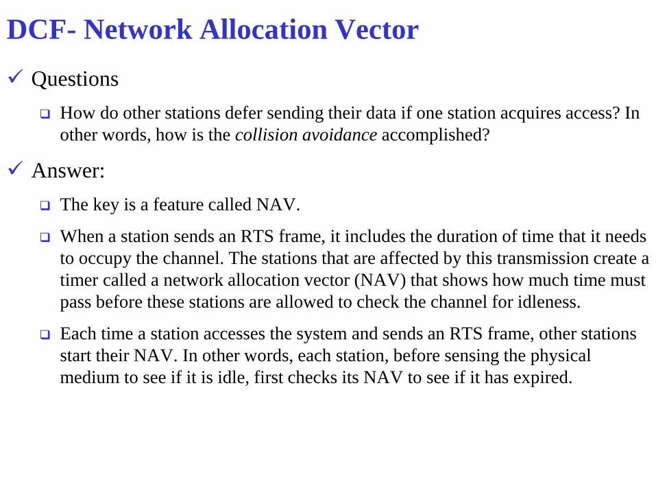
IEEE 802.11 Standard
Standard
approved Bandwidth Frequency
non over
lapping
channel
data rate
(Mb/s) Range Modulation
802.11 1997 83.5 MHz 2.4-2.4835G 3 1,2 20m DSSS, FHSS
802.11a 1999 300 MHz
5.15-5.35G
5.725-5.825G 23, 12
6,12,24,36,48,
54 30m OFDM
802.11 b 1999 83.5 MHz 2.4-2.4835G 3 1, 2, 5.5, 11 35m DSSS/CCK
802.11 g 2003 83.5 MHz 2.4-2.4835G 3
1, 2, 5.5, 11,
6, 9, 12, 18,
24, 36, 48, 54 100m OFDM, DSSS/CCK
802.11 n 2009 83.5 MHz
2.4-2.4835G
5 GHz 3 600 300m Modified OFDM
802.11 AC
Expected
Dec 2013 80-160 MHz < 6 GHz ? 1000 ?
LDPC – Low Density Parity Check
STPC – Space-Time Block Coding
TxBF – Transmit Beam Forming
SGI – 400ns Short Guard Interval
802.11 AD 2003 83.5 MHz 60 GHz ? Up to 7 Gbps ? OFDM, DSSS/CCK

802.11ac
Type 2.4 GHz Mbit/s[d] 5 GHz Mbit/s
AC600 150 433
AC750 300 433
AC1200 300 867
AC1300 400 867
AC1450 450 975
AC1600 300 1,300
AC1750 450 1,300
AC1900 600[e] 1,300
AC2350 600[e] 1,733
AC3200 600[e] 2,600[f]

Multiple Antenna Scenarios
ScenarioTypical client
form factorPHY link rate
Aggregate
capacity
(speed)
One-antenna AP, one-antenna STA, 80 MHz Handheld 433 Mbit/s 433 Mbit/s
Two-antenna AP, two-antenna STA, 80 MHz Tablet, laptop 867 Mbit/s 867 Mbit/s
One-antenna AP, one-antenna STA,
160 MHzHandheld 867 Mbit/s 867 Mbit/s
Two-antenna AP, two-antenna STA,
160 MHzTablet, laptop 1.69 Gbit/s 1.69 Gbit/s
Four-antenna AP, four one-antenna STAs,
160 MHz
(MU-MIMO)
Handheld 867 Mbit/s to each STA 3.39 Gbit/s
•Eight-antenna AP, 160 MHz (MU-MIMO)
one four-antenna STA
•one two-antenna STA
•two one-antenna STAs
Digital TV, Set-top Box,
Tablet, Laptop, PC, Handheld
•3.39 Gbit/s to four-antenna STA
•1.69 Gbit/s to two-antenna STA
•867 Mbit/s to each one-antenna STA
6.77 Gbit/s
Eight-antenna AP, four 2-antenna STAs,
160 MHz
(MU-MIMO)
Digital TV, tablet, laptop, PC 1.69 Gbit/s to each STA 6.77 Gbit/s

WLAN Services Each wireless LAN must provide nine services. These services are
divided into two categories:
Distribution Services
• Distribution services relate to managing cell membership and interacting with stations outside the cell. These services are provided by the access point and deal with station mobility as they enter and leave cells, attaching themselves to and detaching themselves from access points.
Station Services
• Station services relate to activity within a single cell.
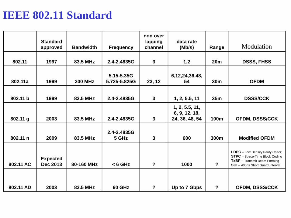
Distribution Services Association: Establishes initial association between station and AP
Used by mobile stations to connect themselves to access point
Mobile station announces its identity and capabilities (data rates supported, need for PCF
services (i.e., polling), and power management requirements.
Re-association: transfer of association from one AP to another (move to another BSS )
If it is used correctly, no data will be lost as a consequence of the handover.
Disassociation: Association termination notice from stations or access point
A station should use this service before shutting down or leaving
The access point may also use it before going down for maintenance.
Distribution: Used to exchange MAC frames from station in one BSS to station in another BSS
Integration: Transfer of data between station on IEEE 802.11 LAN and station on
integrated IEEE 802.x LAN
If a frame needs to be sent through a non-802.11 network with a different addressing
scheme or frame format, this service handles the translation

Station Services
Authentication: Establishes identity of stations to each other;
Access point sends a special challenge frame to see if the mobile station knows the secret key (password) that has been assigned to
De-authentication: Invoked when existing authentication is terminated
When a previously authenticated station wants to leave the network, it is de-authenticated.
Privacy: Prevents message contents to be read by unintended recipient
The encryption algorithm specified is RC4, invented by Ronald Rivest
Delivery of data
Finally, data transmission is what it is all about
Communications Networks – Elex 7710 16
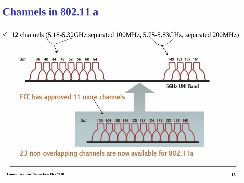
Channels in 802.11 a
12 channels (5.18-5.32GHz separated 100MHz, 5.75-5.83GHz, separated 200MHz)

Channels in 802.11 b/ g
3 non overlapping channels
2.46211
2.45710
2.4529
2.4478
2.4427
2.4376
2.4325
2.4274
2.4223
2.4172
2.4121
Channel in GHzChannel Number
2.46211
2.45710
2.4529
2.4478
2.4427
2.4376
2.4325
2.4274
2.4223
2.4172
2.4121
Channel in GHzChannel Number

Channel Reuse- 802.11a
Channel Reuse- 802.11b/g
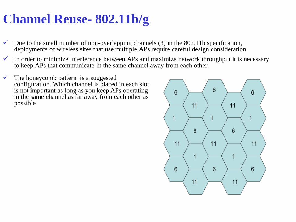
Due to the small number of non-overlapping channels (3) in the 802.11b specification, deployments of wireless sites that use multiple APs require careful design consideration.
In order to minimize interference between APs and maximize network throughput it is necessary to keep APs that communicate in the same channel away from each other.
The honeycomb pattern is a suggested configuration. Which channel is placed in each slot is not important as long as you keep APs operating in the same channel as far away from each other as possible.

Communications Networks – Elex 7710 20
802.11n
Significantly improve PHY layer transmission rate over previous standards
Maintain backward compatibility with existing (802.11a/b/g)
Becomes more reliable in performance
Release date Nov. 2009
Bit rate 600 Mb/s
Range (indoor) 300m
Frequency 2.4 GHz, 5GHz
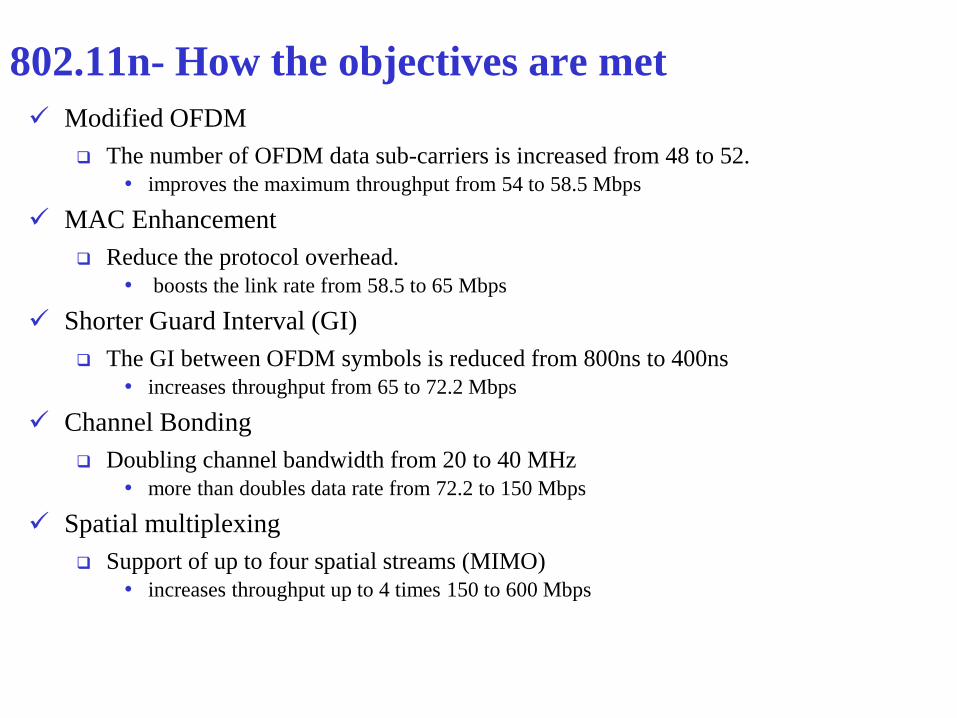
802.11n- How the objectives are met
Modified OFDM
The number of OFDM data sub-carriers is increased from 48 to 52.
• improves the maximum throughput from 54 to 58.5 Mbps
MAC Enhancement
Reduce the protocol overhead.
• boosts the link rate from 58.5 to 65 Mbps
Shorter Guard Interval (GI)
The GI between OFDM symbols is reduced from 800ns to 400ns
• increases throughput from 65 to 72.2 Mbps
Channel Bonding
Doubling channel bandwidth from 20 to 40 MHz
• more than doubles data rate from 72.2 to 150 Mbps
Spatial multiplexing
Support of up to four spatial streams (MIMO)
• increases throughput up to 4 times 150 to 600 Mbps

Multi- Input, Multi Output (MIMO)
MIMO divide a data stream into multiple unique streams
MIMO transmits data streams in same radio channel at same time
MIMO use the advantage of multipath (reflections of the signals)
MIMO receiver combines all streams
MIMO enables 802.11n to operate at much higher data rates than the PHY
would otherwise normally be able to operate for a given transmission.

Capacity Comparison

RANGE AND DATA RATE
As distance from the access point increases, 802.11 products provide reduced data
rates to maintain connectivity.

IEEE 802.i, e & f
802.11i
New security standard
Replaces WEP (which was found to have some problems)
802.11e
Provides QOS support for a, b, & g standards.
802.11f
Recommended practice document for AP inter-operabilit

Co-Channel and Adjacent Channel in Cellular Networks
Co Channel: 1-1, 2-2, ..etc
Same frequency Range
Adjacent Channels: 1-2, 2-3, ..etc
Frequency Range is very close to
each other