Embed Size (px)
Citation preview

bannerengineering.com 43
Wireless I/O, Data and Network Connectivity
Banner's network radios provide the backbone of a very flexible and highly expandable wireless network for industrial environments. The Performance Series centers around a Gateway and up to 47 remotely located Nodes with multiple I/O options. The MultiHop Series uses repeaters to extend the range of the network using multiple “hops” to cover larger distances or to circumvent obstacles (trees, buildings, topology, etc.).
Courtesy of Steven Engineering, Inc - (800) 258-9200 - [email protected] - www.stevenengineering.com

44
point-to-point point-to-multipoint
star
Models I/O Frequency Housing
DX80G9M2S-PN/A
900 MHzLow Profile
DX80G2M2S-P 2.4 GHz
DX80G9M6S-P2 Inputs: Four selectable discrete, two 0–20 mA or 0–10 V analog
Outputs: Four sourcing discrete, two 0–20mA analog
900 MHzIP67
DX80G2M6S-P2 2.4 GHz
DX80G9M2S-P7 Inputs/Outputs: Up to 12 NPN inputs or up to 12 NMOS outputs, or a mix of inputs and outputs not exceeding 12 I/O points
900 MHzIP67
DX80G2M2S-P7 2.4 GHz
DX80G9M6S-P8 Inputs/Outputs: Up to 12 PNP inputs or up to 12 PNP outputs, or a mix of inputs and outputs not exceeding 12 I/O points
900 MHzIP67
DX80G2M6S-P8 2.4 GHz
DX80 Performance Gateways, 10-30 V DC
Models I/O Frequency Housing
DX80G9M6S-PB2Inputs: Two sourcing discrete, two 0-20 mA analogOutputs: Two sourcing discrete, two 0-20 mA analog
900 MHzLow Profile
DX80G2M6S-PB2 2.4 GHz
DX80 Performance Gateways, Board Models Only 10-30 V DC
Low Profile IP67 Housing IP20 Housing
Create point-to-multipoint networks that distribute I/O over large areas. Input and output types include discrete (dry contact, PNP/NPN), analog (0 to 10 V dc, 0 to 20 mA), temperature (thermocouple and RTD), and pulse counter.
Key Features:
• Enhanced Gateways offer increased range in the 900 MHz frequency band
• High density I/O capacity provides up to 12 discrete inputs or outputs or a mix ofdiscrete and analog I/O
• Universal analog inputs allow current or voltage to be selected in the field
Performance Series—Gateways
Courtesy of Steven Engineering, Inc - (800) 258-9200 - [email protected] - www.stevenengineering.com

bannerengineering.com 45
DX80 Performance Gateway Specifications*
Radio Range 900 MHz, 1 Watt: Up to 9.6 km (6 miles) 2.4 GHz, 65 mW: Up to 3.2 km (2 miles)
Minimum Separation Distance 900 MHz, 1 Watt: 4.57 m (15 ft) 2.4 GHz, 65 mW: 0.3 m (1 ft)
Radio Transmit Power 900 MHz, 1 Watt: 30 dBm (1 W) conducted (up to 36 dBm EIRP) 2.4 GHz, 65 mW: 18 dBm (65 mW) conducted, less than or equal to 20 dBm (100 mW) EIRP
Compliance 900 MHz Compliance (1 Watt)FCC ID UE3RM1809: This device complies with FCC Part 15, Subpart C,15.247IC: 7044A-RM1809
2.4 GHz ComplianceFCC ID UE300DX80-2400 - This device complies with FCC Part 15, Subpart C, 15.247ETSI/EN: In accordance with EN 300 328: V1..1 (2012-06)IC: 7044A-DX8024
Spread Spectrum Technology FHSS (Frequency Hopping Spread Spectrum)
Communication Hardware Interface: 2-wire half-duplex RS-485Baud rates: 9.6k, 19.2k (default), or 38.4k via DIP switchesData format: 8 data bits, no parity, 1 stop bit
Communication Protocol Modbus RTU
Link Timeout Gateway: Configurable via User Configuration Tool (UCT) softwareNode: Defined by Gateway
RTD Inputs Sample Rate: 1 second Report Rate: 16 seconds Accuracy: 0.1% of full scale Resolution: 0.1 °C, 15-bit
Operating Conditions –40 °C to +85 °C (–40 °F to +185 °F) (Electronics); –20 °C to +80 °C (–4 °F to +176 °F) (LCD)95% maximum relative humidity (non-condensing)Radiated Immunity: 10 V/m (EN 61000-4-3)
Shock and Vibration IEC 68-2-6 and IEC 68-2-27 Shock: 30g, 11 millisecond half sine wave, 18 shocks Vibration: 0.5 mm p-p, 10 to 60 Hz
Supply Voltage DX80 and “C” Housing Models: 10 to 30 V dc or 3.6 to 5.5 V dc low power option (Outside the USA: 12 to 24 V dc, ±10% or 3.6 to 5.5 V dc low power option)
900 MHz Consumption: Maximum current draw is < 40 mA and typical current draw is < 30 mA at 24 V dc. (2.4 GHz consumption is less)
Construction Polycarbonate housing and rotary dial cover; polyester labels; EDPM rubber cover gasket; nitrile rubber, non-sulphur cured button coversWeight: 0.26 kg (0.57 lbs)DX80 and “C” Housing Models: Mounting: #10 or M5 (SS M5 hardware included)Max. Tightening Torque: 0.56 N·m (5 lbf·in)
Antenna Connection Ext. Reverse Polarity SMA, 50 Ohms Max Tightening Torque: 0.45 N·m (4 lbf·in)
Interface Indicators: Two bi-color LEDs Buttons: Two Display: Six character LCD
Wiring Access DX80 Housing Models: Four PG-7, One 1/2-in NPT, One 5-pin threaded M12/Euro-style male quick-disconnect“C” Housing Models: External terminals
Environmental Rating DX80 models: IEC IP67; NEMA 6“C” Housing Models: IEC IP20; NEMA 1
Certifications
* See datasheet for model specific details
Courtesy of Steven Engineering, Inc - (800) 258-9200 - [email protected] - www.stevenengineering.com
46
point-to-point point-to-multipoint
star
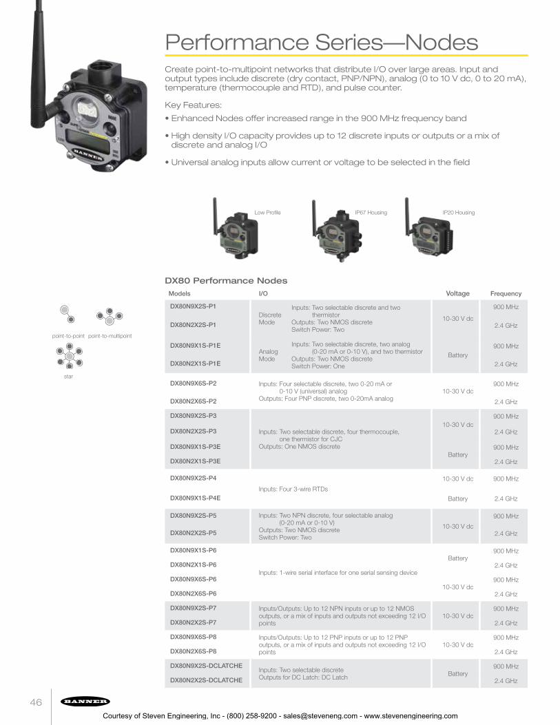
Models I/O Voltage Frequency
DX80N9X2S-P1Discrete Mode
Inputs: Two selectable discrete and two thermistor
Outputs: Two NMOS discreteSwitch Power: Two
10-30 V dc
900 MHz
DX80N2X2S-P1 2.4 GHz
DX80N9X1S-P1EAnalog Mode
Inputs: Two selectable discrete, two analog (0-20 mA or 0-10 V), and two thermistor
Outputs: Two NMOS discreteSwitch Power: One
Battery900 MHz
DX80N2X1S-P1E 2.4 GHz
DX80N9X6S-P2 Inputs: Four selectable discrete, two 0-20 mA or 0-10 V (universal) analog
Outputs: Four PNP discrete, two 0-20mA analog10-30 V dc
900 MHz
DX80N2X6S-P2 2.4 GHz
DX80N9X2S-P3
Inputs: Two selectable discrete, four thermocouple, one thermistor for CJC
Outputs: One NMOS discrete
10-30 V dc900 MHz
DX80N2X2S-P3 2.4 GHz
DX80N9X1S-P3EBattery
900 MHz
DX80N2X1S-P3E 2.4 GHz
DX80N9X2S-P4
Inputs: Four 3-wire RTDs
10-30 V dc 900 MHz
DX80N9X1S-P4E Battery 2.4 GHz
DX80N9X2S-P5 Inputs: Two NPN discrete, four selectable analog (0-20 mA or 0-10 V)
Outputs: Two NMOS discreteSwitch Power: Two
10-30 V dc
900 MHz
DX80N2X2S-P5 2.4 GHz
DX80N9X1S-P6
Inputs: 1-wire serial interface for one serial sensing device
Battery900 MHz
DX80N2X1S-P6 2.4 GHz
DX80N9X6S-P610-30 V dc
900 MHz
DX80N2X6S-P6 2.4 GHz
DX80N9X2S-P7 Inputs/Outputs: Up to 12 NPN inputs or up to 12 NMOS outputs, or a mix of inputs and outputs not exceeding 12 I/O points
10-30 V dc900 MHz
DX80N2X2S-P7 2.4 GHz
DX80N9X6S-P8 Inputs/Outputs: Up to 12 PNP inputs or up to 12 PNP outputs, or a mix of inputs and outputs not exceeding 12 I/O points
10-30 V dc900 MHz
DX80N2X6S-P8 2.4 GHz
DX80N9X2S-DCLATCHEInputs: Two selectable discreteOutputs for DC Latch: DC Latch Battery
900 MHz
DX80N2X2S-DCLATCHE 2.4 GHz
DX80 Performance Nodes
Low Profile IP67 Housing IP20 Housing
Create point-to-multipoint networks that distribute I/O over large areas. Input and output types include discrete (dry contact, PNP/NPN), analog (0 to 10 V dc, 0 to 20 mA), temperature (thermocouple and RTD), and pulse counter.
Key Features:
• Enhanced Nodes offer increased range in the 900 MHz frequency band
• High density I/O capacity provides up to 12 discrete inputs or outputs or a mix ofdiscrete and analog I/O
• Universal analog inputs allow current or voltage to be selected in the field
Performance Series—Nodes
Courtesy of Steven Engineering, Inc - (800) 258-9200 - [email protected] - www.stevenengineering.com

bannerengineering.com 47
DX80 Performance Nodes Specifications*
Radio Range 900 MHz, 1 Watt: Up to 9.6 km (6 miles) 2.4 GHz, 65 mW: Up to 3.2 km (2 miles)
Minimum Separation Distance 900 MHz, 1 Watt: 4.57 m (15 ft) 2.4 GHz, 65 mW: 0.3 m (1 ft)
Radio Transmit Power 900 MHz, 1 Watt: 30 dBm (1 W) conducted (up to 36 dBm EIRP) 2.4 GHz, 65 mW: 18 dBm (65 mW) conducted, less than or equal to 20 dBm (100 mW) EIRP
Compliance 900 MHz Compliance (1 Watt)FCC ID UE3RM1809: This device complies with FCC Part 15, Subpart C,15.247IC: 7044A-RM1809
2.4 GHz ComplianceFCC ID UE300DX80-2400 - This device complies with FCC Part 15, Subpart C, 15.247ETSI/EN: In accordance with EN 300 328: V1.8.1 (2012-06)IC: 7044A-DX8024
Spread Spectrum Technology FHSS (Frequency Hopping Spread Spectrum)
Link Timeout Gateway: Configurable via User Configuration Tool (UCT) softwareNode: Defined by Gateway
Operating Conditions –40 °C to +85 °C (–40 °F to +185 °F) (Electronics); –20 °C to +80 °C (–4 °F to +176 °F) (LCD)“E” Housing Models–40 °C to +65 °C (–40 °F to +149 °F) (Electronics); –20 °C to +80 °C (–4 °F to +176 °F) (LCD)95% maximum relative humidity (non-condensing)Radiated Immunity: 10 V/m (EN 61000-4-3)
Shock and Vibration IEC 68-2-6 and IEC 68-2-27 Shock: 30g, 11 millisecond half sine wave, 18 shocks Vibration: 0.5 mm p-p, 10 to 60 Hz
Supply Voltage DX80 and “C” Housing Models: 10 to 30 V dc or 3.6 to 5.5 V dc low power option (Outside the USA: 12 to 24 V dc, ±10% or 3.6 to 5.5 V dc low power option)
“E” Housing Models: 3.6 V dc low power option from an internal battery or 10 to 30 V dc900 MHz Consumption: Maximum current draw is < 40 mA and typical current draw is < 30 mA at 24 V dc. (2.4 GHz consumption is less)
Construction Polycarbonate housing and rotary dial cover; polyester labels; EDPM rubber cover gasket; nitrile rubber, non-sulphur cured button coversWeight: 0.26 kg (0.57 lbs)DX80 and “C” Housing Models: Mounting: #10 or M5 (SS M5 hardware included)“E” Housing Models: Mounting: 1/4-in or M7 (SS M7 hardware included)Max. Tightening Torque: 0.56 N·m (5 lbf·in)
Antenna Connection Ext. Reverse Polarity SMA, 50 Ohms Max Tightening Torque: 0.45 N·m (4 lbf·in)
Interface Indicators: Two bi-color LEDs Buttons: Two Display: Six character LCD
Wiring Access DX80 Housing Models: Four PG-7, One 1/2-in NPT, One 5-pin threaded M12/Euro-style male quick-disconnect“C” Housing Models: External terminals“E” Housing Models: Two 1/2-in NPT
Environmental Ratingw DX80 models: IEC IP67; NEMA 6“C” Housing Models: IEC IP20; NEMA 1“E” Housing Models: IEC IP65; NEMA 4X
Certifications
* See datasheet for model specific details
Models I/O Frequency
DX80N9X2S-PB1 Inputs: Two NPN discrete, two 0-20 mA analogOutputs: Two NMOS discreteSwitch Power: Two
900 MHz
DX80N2X2S-PB1 2.4 GHz
DX80N9X6S-PB2Inputs: Two PNP discrete, two 0-20 mA analogOutputs: Two PNP discrete, two 0-20 mA analog
900 MHz
DX80N2X6S-PB2 2.4 GHz
DX80 Performance Nodes, Board Models Only, 10-30 V DC
Courtesy of Steven Engineering, Inc - (800) 258-9200 - [email protected] - www.stevenengineering.com

48
point-to-point point-to-multipoint
star
Performance Series—Nodes
Models Power I/O Frequency
DX80N9X1S-P6
D-cell Lithium battery
Inputs: 1-wire serial interface for one 1-wire serial sensing device
900 MHz
DX80N2X1S-P6 2.4 GHz
DX80N9X65-P6
10-30 V dc
900 MHz
DX80N9X65-P6 2.4 GHz
Used With
M12FTH4Q see page 10 Temperature and relative humidity via a 1-wire serial interface
M12FT4Q see page 10 Temperature via a 1-wire serial interface
QM42VT1 see page 8 Vibration and temperature via a 1-wire serial interface
The -P6 Performance Node is an industrial radio device with a 1-wire serial interface that is designed to transmit data from 1-wire serial sensors, such as the Banner Temperature and Humidity (M12FTH4Q) or Vibration and Temperature (QM42VT1) sensors.
Key Features:
• 1-wire serial interface
• Battery-powered models for a completely wireless solution
• Line-powered models for continuous sampling
Performance Series–P6 Nodes
Courtesy of Steven Engineering, Inc - (800) 258-9200 - [email protected] - www.stevenengineering.com

bannerengineering.com 49
DX80 Performance P6 Specifications
Radio Range 900 MHz, 1 Watt: Up to 9.6 km (6 miles) 2.4 GHz, 65 mW: Up to 3.2 km (2 miles)
Minimum Separation Distance 900 MHz, 1 Watt: 4.57 m (15 ft) 2.4 GHz, 65 mW: 0.3 m (1 ft)
Radio Transmit Power 900 MHz, 1 Watt: 30 dBm (1 W) conducted (up to 36 dBm EIRP) 2.4 GHz, 65 mW: 18 dBm (65 mW) conducted, less than or equal to 20 dBm (100 mW) EIRP
Compliance 900 MHz Compliance (1 Watt)FCC ID UE3RM1809: This device complies with FCC Part 15, Subpart C,15.247IC: 7044A-RM1809
2.4 GHz ComplianceFCC ID UE300DX80-2400 - This device complies with FCC Part 15, Subpart C, 15.247ETSI/EN: In accordance with EN 300 328: V1.8.1 (2012-06)IC: 7044A-DX8024
Spread Spectrum Technology FHSS (Frequency Hopping Spread Spectrum)
Link Timeout Gateway: Configurable via User Configuration Tool (UCT) softwareNode: Defined by Gateway
Operating Conditions –40 °C to +85 °C (–40 °F to +185 °F) (Electronics); –20 °C to +80 °C (–4 °F to +176 °F) (LCD)95% maximum relative humidity (non-condensing)Radiated Immunity: 10 V/m (EN 61000-4-3)
Shock and Vibration IEC 68-2-6 and IEC 68-2-27 Shock: 30g, 11 millisecond half sine wave, 18 shocks Vibration: 0.5 mm p-p, 10 to 60 Hz
Supply Voltage Integrated battery models: 3.6 V dc low power option from an internal batteryNon-battery models: 10 to 30 V dc (Outside the USA: 12 to 24 V dc, ±10%)
Construction Polycarbonate housing and rotary dial cover; polyester labels; EDPM rubber cover gasket; nitrile rubber, non-sulphur cured button coversIntegrated battery models: Weight: 0.30 kg (0.65 lbs)Non-battery models: Weight: 0.26 kg (0.57 lbs)Mounting: #10 or M5 (SS M5 hardware included)Max. Tightening Torque: 0.56 N·m (5 lbf·in)
Antenna Connection Ext. Reverse Polarity SMA, 50 Ohms Max Tightening Torque: 0.45 N·m (4 lbf·in)
Interface Indicators: Two bi-color LEDs Buttons: Two Display: Six character LCD
Wiring Access Integrated battery models: One 5-pin threaded M12 Euro-style female quick-disconnectNon-battery models: One 5-pin threaded M12 Euro-style female quick-disconnect and one 5-pin threaded M12 Euro-style male quick-disconnect
Environmental Rating IEC IP67; NEMA 6
Certifications
Courtesy of Steven Engineering, Inc - (800) 258-9200 - [email protected] - www.stevenengineering.com

50
point-to-point point-to-multipoint
star tree
Models Transmit Power Frequency
DX80DR9M-H 250 mW or 1 Watt (DIP switch selectable) 900 MHz
DX80DR2M-H 65 mW (100 mW EIRP) 2.4 GHz
Models I/O Voltage Frequency Housing
DX80DR9M-H1Inputs: Four discrete, two 0-20 mA analog, one
thermistor, one counterOutputs: Two NMOS discreteSwitch Power: TwoSerial interface: RS-485
10-30 V dc 900 MHz IP67
DX80DR9M-H1E Battery 900 MHz IP54
DX80DR2M-H1 10-30 V dc 2.4 GHz IP67
DX80DR2M-H1E Battery 2.4 GHz IP54
DX80DR9M-H2 Inputs: Four discrete, two 0-20 mA analogOutputs: Four sourcing discrete, two 0-20 mA
analogSerial interface: RS-485
10-30 V dc900 MHz
IP67DX80DR2M-H2 2.4 GHz
DX80DR9M-H3
Inputs: Two discrete, four thermocouple, one thermistor (internal)
Outputs: Two NMOS discreteSerial interface: RS-232
10-30 V dc 900 MHz IP67
DX80DR9M-H3E Battery 2.4 GHz IP54
DX80DR2M-H3 10-30 V dc 900 MHz IP67
DX80DR2M-H3E Battery 2.4 GHz IP54
DX80DR9M-H4
Inputs: Four 3-wire Pt100 RTDSerial interface: RS-232
10-30 V dc 900 MHz IP67
DX80DR9M-H4E Battery 2.4 GHz IP54
DX80DR2M-H4 10-30 V dc 900 MHz IP67
DX80DR2M-H4E Battery 2.4 GHz IP54
DX80DR9M-H5 Inputs: Four sinking discrete, four 0-20 mA analogOutputs: Two NMOS discreteSwitch Power: Two Serial Interface: RS-485
10-30 V dc900 MHz
IP67DX80DR2M-H5 2.4 GHz
DX80DR9M-H6Inputs: 1-wire serial interface for one 1-wire serial
sensing deviceBattery
900 MHzIP67
DX80DR2M-H6 2.4 GHz
DX80DR9M-H12 Inputs: Two discrete, two 0-20 mA analog, one thermistor, one SDI-12 or counter
Outputs: Two NMOS discreteSwitch Power: TwoSerial interface: RS-485
10-30 V dc
900 MHz
IP67
DX80DR2M-H12 2.4 GHz
DX80DR9M-DCLATCHE Inputs: Two sinking discreteOutputs for DC Latch: DC Latch
Battery900 MHz
IP54DX80DR2M-DCLATCHE 2.4 GHz
MultiHop Modbus Radios
MultiHop Modbus Radios with I/O
MultiHop Modbus Data Radios extend the range of Modbus or other serial communication networks. Each radio may be set to act as either a master, repeater or slave. Models are available with built in discrete and analog I/O, which can be accessed using the Modbus protocol.
Key Features:
• Self-healing, auto routing RF network with multiple hops extends the network’s range
• Flexible: DIP switch selectable to be a master, repeater or slave
• User-selectable communication between RS-485 and RS-232
MultiHop Modbus Radios
Courtesy of Steven Engineering, Inc - (800) 258-9200 - [email protected] - www.stevenengineering.com

bannerengineering.com 51
MultiHop Modbus Radios with I/O Specifications*
Radio Range 900 MHz, 1 Watt: Up to 9.6 km (6 miles) 2.4 GHz, 65 mW: Up to 3.2 km (2 miles)
Minimum Separation Distance 900 MHz, 1 Watt: 4.57 m (15 ft) 2.4 GHz, 65 mW: 0.3 m (1 ft)
Radio Transmit Power 900 MHz, 1 Watt: 30 dBm (1 W) conducted (up to 36 dBm EIRP) 2.4 GHz, 65 mW: 18 dBm (65 mW) conducted, less than or equal to 20 dBm (100 mW) EIRP
Power FlexPower models: 10 to 30 V dc (Outside the USA: 12 to 24 V dc, ±10%) on the brown wire, or 3.6 to 5.5 V dc low power option on the gray wire 6
Integrated battery models: 3.6 V dc low power option from an internal battery or 10 to 30 V dcMaster radio consumption (900 MHz): Maximum current draw is < 100 mA and typical current draw is < 30 mA at 24 V dc
(2.4 GHz consumption is less)Repeater/slave radio consumption (900 MHz): Maximum current draw is < 40 mA and typical current draw is < 20 mA at 24 V dc
(2.4 GHz consumption is less)
Compliance 900 MHz Compliance (1 Watt)FCC ID UE3RM1809: This device complies with FCC Part 15, Subpart C,15.247IC: 7044A-RM1809
2.4 GHz ComplianceFCC ID UE300DX80-2400 - This device complies with FCC Part 15, Subpart C, 15.247ETSI/EN: In accordance with EN 300 328: V1.8.1 (2012-04)IC: 7044A-DX8024
Spread Spectrum Technology FHSS (Frequency Hopping Spread Spectrum)
Antenna Connection Ext. Reverse Polarity SMA, 50 Ohms Max Tightening Torque: 0.45 N·m (4 lbf·in)
Interface Indicators: Two bi-color LEDs Buttons: Two Display: Six character LCD
Communication Hardware (MultiHop RS-485)
Interface: 2-wire half-duplex RS-485Baud rates: 9.6k, 19.2k (default), or 38.4k via DIP switches; 1200 and 2400 via the MultiHop Configuration ToolData format: 8 data bits, no parity, 1 stop bit
Packet Size (MultiHop) 900 MHz: 175 bytes (85 Modbus registers) 2.4 GHz: 75 bytes (37 Modbus registers)
Intercharacter Timing (MultiHop) 3.5 milliseconds
Housing Polycarbonate housing and rotary dial cover; polyester labels; EDPM rubber cover gasket; nitrile rubber, non-sulphur cured button coversWeight: 0.26 kg (0.57 lbs)M-Hx and M-HxC models: Mounting: #10 or M5 (SS M5 hardware included)M-HxE models: Mounting: 1/4-in or M7 (SS M7 hardware included)Max. Tightening Torque: 0.56 N·m (5 lbf·in)
Wiring Access M-Hx models: Four PG-7, One 1/2-in NPT, One 5-pin threaded M12/Euro-style male quick-disconnectM-HxC models: External terminalsM-HxE models: Two 1/2-in NPT ports
Environmental Rating M-Hx: IEC IP67; NEMA 6“C” Housing Models: IEC IP20; NEMA 1“E” Housing Models: IEC IP65; NEMA 4X
Operating Conditions M-Hx and M-HxC models: –40 °C to +85 °C (–40 °F to +185 °F) (Electronics); –20 °C to +80 °C (–4 °F to +176 °F) (LCD)M-HxE models: –40 °C to +65 °C (–40 °F to +149 °F) (Electronics); –20 °C to +80 °C (–4 °F to +176 °F) (LCD)95% maximum relative humidity (non-condensing)Radiated Immunity: 10 V/m (EN 61000-4-3)
Shock and Vibration IEC 68-2-6 and IEC 68-2-27Shock: 30g, 11 millisecond half sine wave, 18 shocksVibration: 0.5 mm p-p, 10 to 60 Hz
Certifications
* See datasheet for model specific details
Models I/O Frequency
DX80DR9M-HB1 Inputs: Two sinking discrete, two 0 to 20 mA analogOutputs: Two NMOS discreteSwitch Power Outputs: Two
900 MHz
DX80DR2M-HB1 2.4 GHz
DX80DR9M-HB2Inputs: Two sourcing discrete, two 0 to 20 mA analogOutputs: Two sourcing discrete, two 0 to 20 mA analog
900 MHz
DX80DR2M-HB2 2.4 GHz
MultiHop Modbus Radios with I/O — Board Models
Courtesy of Steven Engineering, Inc - (800) 258-9200 - [email protected] - www.stevenengineering.com

52
point-to-point point-to-multipoint
star tree
MultiHop Modbus Radios
Models Power I/O Frequency
DX80DR9M-H6
D-cell Lithium battery Inputs: 1-wire serial interface for one 1-wire serial sensing device
900 MHz
DX80DR2M-H6 2.4 GHz
Used With
M12FTH4Q see page 10 Temperature and relative humidity via a 1-wire serial interface
M12FT4Q see page 10 Temperature via a 1-wire serial interface
QM42VT1 see page 8 Vibration and temperature via a 1-wire serial interface
The -H6 MultiHop Modbus Data Radio has a 1-wire serial interface that is designed to transmit data from 1-wire serial sensors, such as the Banner Temperature and Humidity (M12FTH4Q) and Vibration and Temperature (QM42VT1) sensors.
Key Features:
• 1-wire serial interface
• Battery-powered models for a completely wireless solution
• Tree topology allows for multiple hops to cover longer distances andcircumvent obstacles
MultiHop Modbus –H6
Courtesy of Steven Engineering, Inc - (800) 258-9200 - [email protected] - www.stevenengineering.com
bannerengineering.com 53
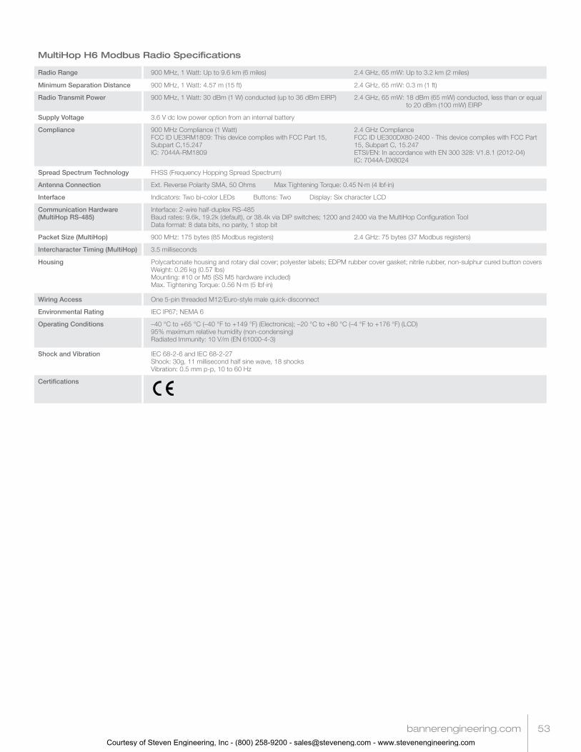
MultiHop H6 Modbus Radio Specifications
Radio Range 900 MHz, 1 Watt: Up to 9.6 km (6 miles) 2.4 GHz, 65 mW: Up to 3.2 km (2 miles)
Minimum Separation Distance 900 MHz, 1 Watt: 4.57 m (15 ft) 2.4 GHz, 65 mW: 0.3 m (1 ft)
Radio Transmit Power 900 MHz, 1 Watt: 30 dBm (1 W) conducted (up to 36 dBm EIRP) 2.4 GHz, 65 mW: 18 dBm (65 mW) conducted, less than or equal to 20 dBm (100 mW) EIRP
Supply Voltage 3.6 V dc low power option from an internal battery
Compliance 900 MHz Compliance (1 Watt)FCC ID UE3RM1809: This device complies with FCC Part 15, Subpart C,15.247IC: 7044A-RM1809
2.4 GHz ComplianceFCC ID UE300DX80-2400 - This device complies with FCC Part 15, Subpart C, 15.247ETSI/EN: In accordance with EN 300 328: V1.8.1 (2012-04)IC: 7044A-DX8024
Spread Spectrum Technology FHSS (Frequency Hopping Spread Spectrum)
Antenna Connection Ext. Reverse Polarity SMA, 50 Ohms Max Tightening Torque: 0.45 N·m (4 lbf·in)
Interface Indicators: Two bi-color LEDs Buttons: Two Display: Six character LCD
Communication Hardware (MultiHop RS-485)
Interface: 2-wire half-duplex RS-485Baud rates: 9.6k, 19.2k (default), or 38.4k via DIP switches; 1200 and 2400 via the MultiHop Configuration ToolData format: 8 data bits, no parity, 1 stop bit
Packet Size (MultiHop) 900 MHz: 175 bytes (85 Modbus registers) 2.4 GHz: 75 bytes (37 Modbus registers)
Intercharacter Timing (MultiHop) 3.5 milliseconds
Housing Polycarbonate housing and rotary dial cover; polyester labels; EDPM rubber cover gasket; nitrile rubber, non-sulphur cured button coversWeight: 0.26 kg (0.57 lbs)Mounting: #10 or M5 (SS M5 hardware included)Max. Tightening Torque: 0.56 N·m (5 lbf·in)
Wiring Access One 5-pin threaded M12/Euro-style male quick-disconnect
Environmental Rating IEC IP67; NEMA 6
Operating Conditions –40 °C to +65 °C (–40 °F to +149 °F) (Electronics); –20 °C to +80 °C (–4 °F to +176 °F) (LCD)95% maximum relative humidity (non-condensing)Radiated Immunity: 10 V/m (EN 61000-4-3)
Shock and Vibration IEC 68-2-6 and IEC 68-2-27Shock: 30g, 11 millisecond half sine wave, 18 shocksVibration: 0.5 mm p-p, 10 to 60 Hz
Certifications
Courtesy of Steven Engineering, Inc - (800) 258-9200 - [email protected] - www.stevenengineering.com

54
star
Models I/OPower Boost Frequency
DX99N9X1S2N0M2X0D1Discrete: Two inputsAnalog: Two inputs (0-20 mA)
10 V
900 MHzDX99N9X1S2N0M2X0D2 18 V
DX99N9X1S2N0V2X0D1Discrete: Two inputsAnalog: Two inputs (0-10 V)
10 V
DX99N9X1S2N0V2X0D2 18 V
DX99N2X1S2N0M2X0D1Discrete: Two inputsAnalog: Two inputs (0-20 mA)
10 V
2.4 GHzDX99N2X1S2N0M2X0D2 18 V
DX99N2X1S2N0V2X0D1Discrete: Two inputsAnalog: Two inputs (0-10 V)
10 V
DX99N2X1S2N0V2X0D2 18 V
DX99N9X1S2N0T4X0D0Thermocouple: Three inputs, one thermistor inputDiscrete: Two (NPN) inputs n/a
900 MHz
DX99N2X1S2N0T4X0D0 2.4 GHz
DX99N9X1S0N0R4X0D0RTD: Four inputs n/a
900 MHz
DX99N2X1S0N0R4X0D0 2.4 GHz
DX99N9X1S2N0B2X0D0Bridge: Two inputsDiscrete: Two inputs n/a
900 MHz
DX99N2X1S2N0B2X0D0 2.4 GHz
DX99N9X1S1S0V2X0D4Inputs (Modbus Mode): One RS-485Inputs (Voltage Mode): Two analog, one discrete 13 V
900 MHz
DX99N2X1S1S0V2X0D4 2.4 GHz
DX99N9X1S1N0M3X0D5 Inputs: One analog input with a 29 second warm-up time; one sinking discrete
Additional Input Configurations: One 3-wire 100-Ohm Platinum RTD, one sinking discrete, and two analog (0-20 mA)
19 V900 MHz
DX99N2X1S1N0M3X0D5 2.4 GHz
DX99 FlexPower® Nodes — Class 1, Div 1 and Zone 0 (metal housing)
Key Features:
• The DX99 is a state-of-the-art combination of wireless communication,battery technology and intrinsically safe electronics
• All models are certified for operation in Class I, Division 1 and ATEX Zone 0 locations
• Networks formed using DX80 Performance Gateways installed beyond the hazardousarea and one or more Nodes operating in the same frequency band
• Both 900 MHz 150 mW and 2.4 GHz 63 mW models are available
Intrinsically Safe Nodes
Courtesy of Steven Engineering, Inc - (800) 258-9200 - [email protected] - www.stevenengineering.com

bannerengineering.com 55
DX99 FlexPower Node Specifications
Radio Range 900 MHz, 150 mW: Up to 4.8 km (3 miles) 2.4 GHz, 65 mW: Up to 3.2 km (2 miles)
Minimum Separation Distance 900 MHz, 150 mW: 2 m (6 ft) 2.4 GHz, 65 mW: 0.3 m (1 ft)
Radio Transmit Power 900 MHz, 150 mW: 21 dBm (150 mW) conducted 2.4 GHz, 65 mW: 18 dBm (65 mW) conducted, less than or equal to 20 dBm (100 mW) EIRP
Compliance 900 MHz ComplianceFCC ID TGUDX80 - This device complies with FCC Part 15, Subpart C, 15.247IC: 7044A-DX8009
2.4 GHz ComplianceFCC ID UE300DX80-2400 - This device complies with FCC Part 15, Subpart C, 15.247ETSI/EN: In accordance with EN 300 328: V1.8.1 (2012-04)IC: 7044A-DX8024
Spread Spectrum Technology FHSS (Frequency Hopping Spread Spectrum)
RS-485 Inputs Interface: 2-wire half-duplex RS-485Baud Rates: 9.6k, 19.2k (default), or 38.4kData Format: 8 data bits, no parity, 1 stop bit (even and odd parity selection are available)
Communication Hardware (MultiHop RS-485)
Interface: 2-wire half-duplex RS-485Baud rates: 9.6k, 19.2k (default), or 38.4k via DIP switches; 1200 and 2400 via the MultiHop Configuration ToolData format: 8 data bits, no parity, 1 stop bit
Link Timeout Gateway: Configurable via User Configuration Tool (UCT) softwareNode: Defined by Gateway
Supply Voltage 3.6 V dc low power option from an internal battery
Power Consumption Consumption: Application dependant
Housing Glass and cast aluminium with chromating and chemically-resistant paint (outside only)
Antenna Connection Ext. Reverse Polarity SMA, 50 OhmsMax Tightening Torque: 0.45 N·m (4 lbf·in)
Interface Indicators: Two bi-color LEDsButtons: TwoDisplay: Six character LCD
Wiring Access Two 1/2-in NPT ports, one 3/4-in NPT port (internal threads)
Environmental Rating IEC IP68
Operating Conditions –40 °C to +65 °C (–40 °F to +149 °F) (Electronics); –20 °C to +80 °C (–4 °F to +176 °F) (LCD)95% maximum relative humidity (non-condensing)Radiated Immunity: 10 V/m (EN 61000-4-3)
Shock and Vibration IEC 68-2-6 and IEC 68-2-27Shock: 30g, 11 millisecond half sine wave, 18 shocksVibration: 0.5 mm p-p, 10 to 60 Hz
Certifications CSA: Class I, Division 1, Groups A, B, C, D; Class II, Division 1, Groups E, F, G; Class III, Division 1 (Ex ia IIC T4 / AEx ia IIC T4)
Certificate: 2008243
LCIE/ATEX: Zone 0 (Category 1G) and 20 (Category 1D), Temperature Class T4 (II 1 GD / Ex ia IIC T4/Ex iaD 20 IP68 T82°C) Certificate: LCIE 08 ATEX 6098 X
Special Conditions for Safe Use imposed by Intrinsic Safety Certificate LCIE 08 ATEX 6098 X: Ambient temperature range is –40 to 70 °C. Sure Cross® DX99 FlexPower devices can only be connected to Intrinsically Safe certified equipment or simple apparatus as defined by EN 60079-11. All connected equipment must comply with the Entity Parameters (Safety Parameters) listed in the Control Drawings (p/n 141513). The device must only use a lithium battery manufactured by XENO, type XL-205F.
K50 and K30 Hazardous IndicatorsBanner’s K50 and K30 Indicator Lights for hazardous areas have a smooth 50 or 30 mm diameter dome that provides uniform illumination from all directions.
• Up to three colors in one device and five colors to choose from
• Models rated to IP67 and IP69K for use in harsh environments
• Unique design appears gray when OFF, eliminating false indication from ambient light
• Easy mounting and configuration
• Worldwide IECEx approval for quicker access into countries outside Europe and North America
Courtesy of Steven Engineering, Inc - (800) 258-9200 - [email protected] - www.stevenengineering.com

56
point-to-point point-to-multipoint
star tree
DXM Controllers
Models Description Frequency
DXM100-B1R1 DXM100 Controller preconfigured as a protocol converter 900 MHz
DXM100-B1R3 DXM100 Controller preconfigured as a protocol converter 2.4 GHz
The DXM100 Controller is an industrial wireless controller developed to facilitate Ethernet connectivity and Industrial Internet of Things (IIoT) applications. Available with an internal DX80 Gateway or a MultiHop Data Radio, this powerful Modbus communications device connects local wireless networks with the internet and/or host systems.
Key Features:
• ISM radios available in 900 MHz and 2.4 GHz for local wireless network
• Converts Modbus RTU to Modbus TCP/IP or Ethernet I/P
• Logic controller can be programmed using action rules and text language methods
• Micro SD card for data logging
• Email and text alerts
• Local I/O options: universal inputs, NMOS outputs, and analog outputs
• Powered by 12 to 30 V dc, 12 V dc solar panel, or battery backup
• RS-232, RS-485, and Ethernet communications ports; and a USB configuration port
• LCD display for I/O information and user programmable LED’s
DXM100 Wireless Controller
Courtesy of Steven Engineering, Inc - (800) 258-9200 - [email protected] - www.stevenengineering.com
bannerengineering.com 57
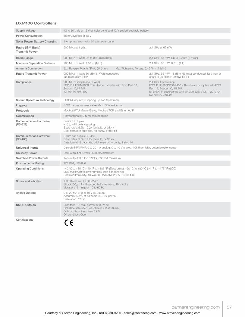
DXM100 Controllers
Supply Voltage 12 to 30 V dc or 12 V dc solar panel and 12 V sealed lead acid battery
Power Consumption 35 mA average at 12 V
Solar Power Battery Charging 1 Amp maximum with 20 Watt solar panel
Radio (ISM Band) Transmit Power
900 MHz at 1 Watt 2.4 GHz at 65 mW
Radio Range 900 MHz, 1 Watt: Up to 9.6 km (6 miles) 2.4 GHz, 65 mW: Up to 3.2 km (2 miles)
Minimum Separation Distance 900 MHz, 1 Watt: 4.57 m (15 ft) 2.4 GHz, 65 mW: 0.3 m (1 ft)
Antenna Connection Ext. Reverse Polarity SMA, 50 Ohms Max Tightening Torque: 0.45 N·m (4 lbf·in)
Radio Transmit Power 900 MHz, 1 Watt: 30 dBm (1 Watt) conducted (up to 36 dBm EIRP)
2.4 GHz, 65 mW: 18 dBm (65 mW) conducted, less than or equal to 20 dBm (100 mW EIRP)
Compliance 900 MHz Compliance (1 Watt)FCC ID UE3RM1809: This device complies with FCC Part 15, Subpart C,15.247IC: 7044A-RM1809
2.4 GHz ComplianceFCC ID UE300DX80-2400 - This device complies with FCC Part 15, Subpart C, 15.247ETSI/EN: In accordance with EN 300 328: V1.8.1 (2012-04)IC: 7044A-DX8024
Spread Spectrum Technology FHSS (Frequency Hopping Spread Spectrum)
Logging 8 GB maximum; removable Micro SD card format
Protocols Modbus RTU Master/Slave, Modbus TCP, and Ethernet/IP
Construction Polycarbonate; DIN rail mount option
Communication Hardware (RS-322)
3-wire full duplex–15 to +15 Volts signalingBaud rates: 9.6k, 19.2k (default), or 38.4k Data format: 8 data bits, no parity, 1 stop bit
Communication Hardware (RS-485)
3-wire half duplex RS-485Baud rates: 9.6k, 19.2k (default), or 38.4k Data format: 8 data bits, odd, even or no parity, 1 stop bit
Universal Inputs Discrete NPN/PNP, 0 to 20 mA analog, 0 to 10 V analog, 10k thermistor, potentiometer sense
Courtesy Power One; output at 5 volts , 500 mA maximum
Switched Power Outputs Two; output at 5 to 16 Volts, 500 mA maximum
Environmental Rating IEC IP67; NEMA 6
Operating Conditions –40 °C to +85 °C (–40 °F to +185 °F) (Electronics); –20 °C to +80 °C (–4 °F to +176 °F) (LCD)95% maximum relative humidity (non-condensing)Radiated Immunity: 10 V/m, 80-2700 MHz (EN 61000-4-3)
Shock and Vibration IEC 68-2-6 and IEC 68-2-27Shock: 30g, 11 millisecond half sine wave, 18 shocksVibration: .5 mm p-p, 10 to 60 Hz
Analog Outputs 0 to 20 mA or 0 to 10 V dc outputAccuracy: 0.1% of full scale +0.01% per °CResolution: 12 bit
NMOS Outputs Less than 1 A max current at 30 V dcON-state saturation: less than 0.7 V at 20 mAON condition: Less than 0.7 VOff condition: Open
Certifications
Courtesy of Steven Engineering, Inc - (800) 258-9200 - [email protected] - www.stevenengineering.com

58
Additional Devices and Sensors
Models I/O
SM312LPQD-78447 MINI-BEAM®, Low Power, 5 V, polarized retroreflective, 3 m
SM312DQD-78419 MINI-BEAM®, Low Power, 5 V, diffuse, 38 cm
QT50ULBQ6-75390 Ultrasonic, QT50U, 200 mm to 8 m range
QS30WEQ WORLD-BEAM® Photoelectric Emitter, QS30 (Max Range: 100 ft, 10x excess gain at 50 ft), 1-wire serial interface
QS30WRQ WORLD-BEAM® Photoelectric Receiver, QS30 (Max Range: 100 ft, 10x excess gain at 50 ft), 1-wire serial interface
Sensors Optimized for Use with FlexPower® Devices
Models I/O
DX85M6P6 DX85 Modbus RTU Remote I/O, 6 Discrete IN, 6 Discrete OUT
DX85M4P4M2M2 DX85 Modbus RTU Remote I/O, 4 Discrete IN, 4 Discrete OUT, 2 Analog IN, 2Analog OUT (0 to 20 mA)
DX85M4P8 DX85 Modbus RTU Remote I/O, 4 Discrete IN, 8 Discrete OUT
DX85M8P4 DX85 Modbus RTU Remote I/O, 8 Discrete IN, 4 Discrete OUT
DX85M0P0M4M4 DX85 Modbus RTU Remote I/O, 4 Analog IN, 4 Analog OUT (0 to 20 mA)
DX85M-P7 DX85 Modbus RTU Remote I/O, Up to 12 sinking inputs or up to 12 NMOS sinkingoutputs (for a total of 12 I/O)
DX85M-P8 DX85 Modbus RTU Remote I/O, Up to 12 sourcing inputs or up to 12 sourcingoutputs (for a total of 12 I/O)
NOTE: Add a “C” to the end of any DX85 model to order the I/O mix with an IP20 housing. The IP20 models are Class I, Division 2 certified when installed in a suitable enclosure.
DX85 Modbus RTU Remote I/O DevicesThese remote I/O devices have a Modbus interface and are used to expand the I/O of the Gateway or the Modbus host.
IP20 Housing
IP67 Housing
Courtesy of Steven Engineering, Inc - (800) 258-9200 - [email protected] - www.stevenengineering.com

bannerengineering.com 59
Models I/O
BWA-THERMISTOR-001 NTC Thermistor, 2.2 KOhms, +/-0.2%C, blue bead (For models: DX80N9X2S2N2T/C, DX99N9X2S2N0T4X0A0, and DX99N9X1S2N0T4X0D0)
BWA-THERMISTOR-002 NTC Thermistor, 10 KOhms, +/-0.2%C, black bead (For Performance models - P1/C/E, and MultiHop models M-H1/C/E), 2 pack
BWA-S612-30-100 NoShok Series 612 Submersible Level Transmitter, model 612-30-1-1-N-100, 0 to 30 psig, 100' cable
BWA-S612-15-100 NoShok Series 612 Submersible Level Transmitter, model 612-15-1-1-N-100, 0 to 15 psig, 100' cable
BWA-625-5000-1-1-8-25 NoShok Series 625 Intrinsically Safe Pressure Transmitter, model 625-5000-1-1-8-25, 0 to 5000 psig, 1/2-in NPT,4–20mA, M12 QD
BWA-625-10000-1-1-8-25 NoShok Series 625 Intrinsically Safe Pressure Transmitter, model 625-10000-1-1-8-25, 0 to 10000 psig, 1/2-in NPT, 4–20mA, M12 QD
BWA-P-RKGV 5.33T-1727-2.0 Cable, female M12 4-pin, blue PVC, SS connector, for NoShok Series 625 IS Pressure Transmitter
BWA-ACC-SEN-SDI Acclima SDI-12 Soil Moisture Transducer
Other Sensors or Sensor Components
GPS50M GPS Module Specifications
Power Requirements 5 to 30 V dc
Current Maximum: < 0.5 WPower Save Mode ON Typ. Average: 4 mA at 24 V dcPower Save Mode OFF Tye. Average: 10 mA at 24 V dc
Indicators Green flashing: Power ON Amber flashing: Modbus communication active
Indicators Green flashing: Power ON Red flicker: Serial Tx
Operating Temperature -40 to +85 ˚C (-40 to +185 ˚F)
GPS Features • SiRF Star IV GPS chip• Satellite-based augmentation systems:
WAAS, EGNOS, MSAS, GAGAN
• High sensitivity navigation engine (PVT) tracks as low as –163 dBm
• Update Rate: 1 Hz
Communication • Interface: RS-485 serial• Baud rates: 9.6k, 19.2k (default), or 38.4k• Data format: 8 data bits, no parity (default),
1 stop bit (even or odd parity available)
• Do not use termination resistor• Protocol: Modbus RTU
Shock and Vibration • IEC 68-2-6 and IEC 68-2-27• Shock: 30g, 11 millisecond half wave, 18 shocks• Vibration: 0.5 mm p-p, 10 to 60 Hz
Accuracy • Positional error of less than 2.5 m (8') with augmentation• Positional error of less than 10 m (33') with no augmentation
GPS50M GPS ModuleLow power consumption, ability to withstand harsh environments, flexible power supply requirements and Modbus RTU communications makes this module ideal for the industrial market.
• Self-contained GPS Module for industrial use.• Flexible Power Requirements: 5 to 30 V dc with power consumption as low as 100 mW• Positional error of less than 2.5 meters• Self-contained for harsh environment; IP69K-rated
Courtesy of Steven Engineering, Inc - (800) 258-9200 - [email protected] - www.stevenengineering.com