Embed Size (px)
Citation preview

2268 JOURNAL OF LIGHTWAVE TECHNOLOGY, VOL. 28, NO. 16, AUGUST 15, 2010
Wireless Hybrid Mode Locked Lasers for NextGeneration Radio-Over-Fiber Systems
Bilal A. Khawaja, Student Member, IEEE, and Martin J. Cryan, Senior Member, IEEE
Abstract—This paper demonstrates a novel technique to wire-lessly injection lock a state-of-the-art 40 GHz mode locked laserand shows baseband data transmission using such a technique.This allows mode locked lasers to be used as millimeter wave mod-ulated data sources for next generation Radio-over-Fiber systems.Binary phase shift keying data transmission rates of up to 22 Mb/shave been demonstrated for a short wireless range of 10 cm. Thesedevices can also be used as millimeter wave phase shifters for ad-vanced antenna beam steering systems.
Index Terms—Beam steering systems, binary phase shift keying,millimeter wave, mode locked lasers, phase shifters, radio-over-fiber, wireless injection locking.
I. INTRODUCTION
T HE demand for high speed data transmission has in-creased dramatically over the past few years through the
evolution of wireless communications networks. To meet theserequirements the millimeter-wave (mm-wave) frequency bandsare becoming attractive because they offer large transmissionbandwidths and also overcome the problem of spectral con-gestion at lower frequency ranges [1], [2]. For example, thereare recently released standards for consumer based systemsfor the distribution of high definition TV signals around thehome operating at 4 Gb/s for a wireless range of 10 m witha 60 GHz carrier [3]. To deliver similar data rates at 60 GHzin an in-building or campus wide scenario leads to hundredsof antenna deployments which results in major challenges forthe current wired infrastructure. It has long been recognisedthat Radio-over-Fiber (RoF) links could play an important rolein such systems when high-frequency wireless signals needto be distributed over many 100’s of meters. The use of RoFtechniques can result in a simplified overall system design sinceboth RF carrier generation and data modulation can be done ata central base station [4]–[8].
For 60 GHz RoF systems to be feasible, cost will be a veryimportant factor and the main issue for RoF solutions is thecost of modulating a laser at 60 GHz. An alternate solutionwould be the direct modulation of a laser [9] at 4 Gb/s forhigh speed data transmission over fiber but this would still
Manuscript received October 28, 2009; revised January 28, 2010, March 25,2010, April 26, 2010; accepted May 05, 2010. Date of publication May 24, 2010;date of current version August 02, 2010. The Ph.D. work of B. A. Khawajawas supported in part by the National University of Science and Technology(NUST), Islamabad, Pakistan. This work was supported in part by the Depart-ment of Electrical and Electronic Engineering, University of Bristol, U.K.
The authors are with the Photonics Research Group, Department of Elec-trical and Electronic Engineering, University of Bristol, Bristol, BS8 1UB, U.K.(e-mail: [email protected]; [email protected]).
Digital Object Identifier 10.1109/JLT.2010.2050461
require a 60 GHz local oscillator at the remote end for dataup/down conversion using mixers which could increase thecost significantly. Traditionally, modulation at 60 GHz wouldbe done with an expensive electro-optic modulator (EOM) [2]although more recently electro-absorption modulators have alsobeen explored [10]. Up to now, several EOM based methodsfor mm-wave signal generation and data modulation usingMach–Zehnder modulator (MZM) have been proposed [2],[11]–[16]. Among these methods, double sideband (DSB) mod-ulation schemes have a critical drawback caused by chromaticdispersion [11]. Whereas single sideband (SSB) modulationschemes [12], [13] which overcome the dispersion issue tend tohave low signal-to-noise (SNR) characteristics. Other possibleschemes include optical carrier suppression and optical phasemodulation with optical filtering [14]–[16]. These have beenapplied to many RoF systems for better SNR characteristics ofthe generated mm-wave signals. Other techniques to generatemm-wave signals using semiconductor photonic devices havealso been explored; some of the important ones are two-modelocked Fabry–Perot (FP) slave lasers [17], dual parallel injec-tion locked FP laser [18] and an optical heterodyne techniqueusing two single mode lasers [19]. In the optical heterodynetechnique, two single-mode lasers beat together to generate amm-wave signal at their optical frequency difference in a fastphotodiode (PD).
One interesting, potentially low cost, solution is the use ofmode locked lasers (MLLs) that can be designed to operate atmm-wave pulse repetition frequencies [20]. MLLs are a veryattractive solution for number of applications including opticalclock extraction, optical time division multiplexing, packetswitching, RoF systems and microwave/mm-wave signal gen-eration [4], [20]–[22]. Commercially available passive/hybridMLLs are selected for this purpose because they offer highstability [20] and good phase noise performance [21]. Typicallypassive MLLs are fabricated from a standard FP laser whichis modified to include a short saturable absorber (SA) sectionwithin the cavity. When the SA section is reversed biased,longitudinal modes within the cavity become phase locked.This results in the pulsed emission of light with a repetitionfrequency determined by the cavity round trip time. For typicaldevice lengths around 1 mm this results in mm-wave repetitionfrequencies and thus in combination with high speed PDs canbe used as mm-wave wave sources. It is well known that whena continuous wave RF signal is injected into the MLL cavity,close to its free running frequency, the MLL output signalsynchronizes itself to the external signal. This condition isknown as hybrid mode-locking. Such hybrid MLLs can alsobe used as mm-wave phase shifters under RF injection locking
0733-8724/$26.00 © 2010 IEEE

KHAWAJA AND CRYAN: WIRELESS HYBRID MODE LOCKED LASERS 2269
[23], this shows their potential to be used in next generationsmart antenna beam steering systems for WLANs. It has alsobeen shown that in hybrid MLLs if the RF injected signal isitself modulated with baseband data, this data is imposed on theoptical carrier such that it can be demodulated after a high speedPD. The first examples of this were shown sometime ago [24],[25]. In [24] 50 Mb/s differential phase-shift keying (DPSK)data transmission was demonstrated over a few meters of fiberat a 45 GHz carrier frequency. In [25] subcarrier transmissionof two 2.5 Mb/s binary phase shift keying (BPSK) channelswas demonstrated over 400 m of single mode fiber (SMF).
An alternate data transmission approach is the use ofMLLs with EOMs. Here, MLLs running under the hybridmode-locking condition are used with an external EOM forhigh speed data transmission. Ahmed et al. [4] showed that a 37GHz hybrid MLL with an EOM can be used to transmit mul-tiple video channels and 255 Mb/s BPSK data simultaneouslyover 10 km of SMF. They also theoretically proved that the useof hybrid MLLs as a mm-wave optical carrier source solvesthe problem of chromatic dispersion in SMF links operatingat the link lengths of km. Quite recently, 240 GHz [26]ultra broadband RoF transmission was achieved using an activeMLL and an EOM and baseband data transmission of 3 Gb/swas demonstrated over 1 km of SMF. However, it is felt that theuse of EOMs will not produce a sufficiently low cost solutionfor wide spread commercial deployment.
Therefore, this paper focuses on the modulator-free techniqueintroduced in [24], [25] and explores the possibility of inte-grating a planar antenna along side the MLL to produce highlyintegrated low cost modules. This approach is being explored atlower frequencies and is termed as photonic active integratedantenna [27], [28]. The advantage in this case is that in themm-wave bands antennas become sufficiently small such thatthey could be integrated directly on the same semiconductorsubstrate as the laser. This has already been implemented forhigh speed PDs [29], but to the author’s knowledge has notbeen explored for lasers. Such fully monolithic photonic ac-tive integrated antenna chips could radically reduce the costs ofmm-wave RoF systems and could lead to the widespread adop-tion of this technology. A typical mm-wave RoF system archi-tecture is shown in Fig. 1 where a central base station feeds afiber network which delivers mm-wave modulated light to lowcost remote antenna units. An important advantage of usinga RoF system is that long ( kms) link lengths can be imple-mented meaning large building and campus wide networks canbe covered with one central base station. The advantages ofusing fibre over copper based approaches are that the link lossis essentially independent of the carrier frequency and the lossis so low ( 0.2 dB/km) that the system design is virtually in-dependent of link length. Dispersion induced fading [30] canbe an issue with longer RoF links, but for links in the few kmrange it is not that critical. In the implementation proposed herethe remote antenna units will contain high speed PDs for thedownlink and wireless hybrid MLLs for the uplink. The MLLscan also be used for mm-wave signal generation and modula-tion at the central base station for downlink data transmission.Fig. 1 also shows the use of steerable beams which could in
Fig. 1. Schematic of mm-wave RoF system architecture.
Fig. 2. Schematic of MLL mounting configuration.
principle be implemented using the phase shifting ability ofinjection locked systems [23]. However, to implement beamsteering multiple laser chips and optical combiners would berequired, this will be studied in future work. The paper is orga-nized as follows: Section II shows 40 GHz MLL characteriza-tion results, including RF injection locking and phase shifting.In Section III, a 40 GHz patch antenna design and wireless hy-brid mode-locking results are presented. Section IV presentsbaseband data transmission results using both hybrid MLL andwireless hybrid MLLs and Section V draws conclusions.
II. 40 GHZ MODE-LOCKED LASER CHARACTERIZATION
A. Passive Mode-Locking and Tuning Range
The state-of-the-art 1550 nm monolithic InP-based multiplequantum-well devices have been used for the measurements.They possess a distributed bragg reflector, an integratedsaturable absorber (SA), gain and phase sections as shownschematically in Fig. 2. The multi-section MLL devices weresupplied by HHI, Berlin [20] having a total device length of1080 m which produces an output pulse repetition frequencyof around 40 GHz. Fig. 2 also shows the device mountingconfiguration. Two MLL devices, MLL-A2 and MLL-A3 wereused for the measurements. A brass fixture was used to mountthe MLL for testing. The SA section was connected using agold bond wire and a 50 transmission line with a K-connectorto apply both RF power and reverse bias to the SA section forhybrid mode-locking. A separate gold plated ceramic block wasconnected to the gain section of the MLL using a bond wire and

2270 JOURNAL OF LIGHTWAVE TECHNOLOGY, VOL. 28, NO. 16, AUGUST 15, 2010
Fig. 3. (a), (b) Measured millimetre-wave passive mode-locking RF spectra (���� � � GHz, Res �� � MHz) and (c), (d) Optical Spectra at � � �� mA,� � ��� V for MLL-A2 and MLL-A3 respectively.
a DC probe was used to apply forward bias to the gain section.It should be noted that phase and distributed bragg reflectorsections were unbiased for all the MLL measurements.
Both MLL-A2 and MLL-A3 have excellent optical outputpowers of 7.5 mW and 8.5 mW respectively. These were mea-sured into a single mode fiber lens at 110 mA gain section cur-rent and operating temperature of 15 C. Passive mode-lockingof the MLLs was then performed and the mm-wave spectrumwas observed using an Agilent 50 GHz (E4448A) spectrum ana-lyzer and a high speed t Photonics 50 GHz PD. Fig. 3(a), (b)shows the passive mode locked RF spectra and Fig. 3(c), (d)shows optical spectra respectively. The gain and SA sectionsof the MLLs were biased at 110 mA and V forMLL-A2 and MLL-A3 respectively. The slight differences inthe spectra in terms of passive mode locked frequency, noisefloor and power level, reflect the device-to-device repeatabilityfor this type of semiconductor device. The free running fre-quency of the MLL can be controlled by the SA voltage andgain section bias and has a range of 446.7 MHz [23] and 466.6MHz for MLL-A2 and MLL-A3 respectively.
B. MLL Injection Locking
Hybrid mode-locking of the MLL can be achieved by in-jecting a continuous wave external RF signal into the MLLcavity close to its passively mode locked frequency. The MLLrepetition rate is then controlled by the applied external RFsignal over a range over frequencies known as the lockingrange. Hybrid mode-locking of these MLLs has been exten-sively characterized in [20] and recently, a novel approach hasbeen presented by injection locking the MLL using a vectornetwork analyzer (VNA) [23] which exploits the phase lockednature of a VNA. Fig. 4 shows the measurement setup.
In the setup, port 1 of a VNA is used to input a mm-wavesignal into the SA section to obtain injection locking. Light iscoupled out of the laser using a single-mode fiber lense and intoa high speed PD and back into port 2 of the VNA. The gain sec-tion was biased at 110 mA and the SA section was biased atrange of voltages from V to V. The maximum VNAoutput power is dBm which is quite low and to overcomethis, a dB gain SHF (804TL) mm-wave high power ampli-fier (HPA) was used to increase the amount of RF input power

KHAWAJA AND CRYAN: WIRELESS HYBRID MODE LOCKED LASERS 2271
Fig. 4. MLL Injection Locking measurement setup using mm-wave amplifierand VNA.
to the MLL for wider locking ranges. An RF power ofdBm was injected into the laser fixture after the HPA, bias-t andthe V-K connectors. The loss from connector to SA section isestimated from separate fixture measurements to be dB,thus the input power to the SA section is estimated to bedBm. The VNA measures the link gain of the system. Thelocking range can be observed as a flat “plateau” in the am-plitude response as shown in Fig. 6 where the swept frequencyof the VNA is locking the free running frequency of the MLL.
This technique not only allows a straight forward character-ization of mm-wave injection locking between MLL and VNAbut also provides an easy characterization of mm-wave phaseshift induced due to RF injection locking of the two systems. Ac-cording to classical electronic injection-locked oscillator (ILO)theory [31]–[33], the phase of an ILO will shift by 180 (to ) as the injected signal is tuned across the oscillator’slocking range, as given by the formula in (1)
(1)
where and are the output and injected frequencies respec-tively and is the locking range of the ILO.
Fig. 5 below shows MLL-A2 injection locked measuredamplitude and phase response and it can be seen that an overallphase shift of 172 is observed. It is important to note here thatthe injection locked MLL presented in [23] and in this paper isbehaving like an electronic ILO, but in reality it is an optoelec-tronic system which is fundamentally different and more com-plex than an electronic ILO system.
The widest locking range obtained is 63.84 MHz fromMLL-A3 as shown in Fig. 6. This is the highest locking rangeachieved so far from the VNA based injection locking techniqueintroduced in [23]. However, these lasers have not been opti-mized for wide locking range and other MLL configurationshave shown much wider locking ranges, upto 500 MHz–2 GHz[20].
It is also well known that the locking range is dependenton the amount of injected power with greater input power pro-ducing increased locking ranges [31]–[33], as given by the for-mula in (2)
(2)
Fig. 5. Zoom-in on � amplitude response showing plateau across lockingrange and its relative phase shift of 172 measured using MLL-A2.
Fig. 6. Zoom-in on � amplitude response showing plateau across lockingrange of 63.84 MHz for � � ����V and�����V measured using MLL-A3.
where is the injected RF power to the MLL.The effect of change in SA injection power on the
locking range is now studied. To this end, the MLL-A2 is againinjection locked using a mm-wave ( dB gain) amplifierusing similar setup configuration shown in Fig. 4. The gainand SA bias were fixed at mA and Vrespectively. The effect of changing on the locking rangeis shown in Fig. 7. It can be seen that a locking range of 3.895MHz is observed for dBm and as the injectionpower level decreases the locking range decreases as expectedfrom (2). Fig. 7 also shows that the link gain level and centrefrequency of the locking range are dependent on the injectedpower, this is most likely due the highly non-linear nature ofthe injection locked system.
The locking range can now be plotted against square rootof the injected power in order to understand whether the MLLsystem is behaving like an electronic ILO.
The MLL locking range is extracted from Fig. 7 for each SAinjection power. It can be seen in Fig. 8 that the locking range isreasonably linear with respect to the from 0.35 mWto 0.7 . Outside this range the data no longer agreeswith the linear fit given in (2) and this is believed to be due tocomplex nature of the locking process here.
III. WIRELESS HYBRID MODE-LOCKED LASER
Wireless hybrid mode-locking is a new concept where a MLLis combined with a planar antenna such that it can be wirelessly

2272 JOURNAL OF LIGHTWAVE TECHNOLOGY, VOL. 28, NO. 16, AUGUST 15, 2010
Fig. 7. Zoom-in on� amplitude response showing locking range for differentSA injection powers measured using MLL-A2.
Fig. 8. Shows the dependence of Injection locking range on square root oflocking signal power.
injection locked for baseband data transmission. This techniquehas been recently introduced and demonstrated in [34], [35] andis a first step towards the full monolithic integration of MLLswith antennas and amplifiers. There are issues with the integra-tion of amplifiers in this case, but there are a number of novelschemes that have been suggested [36].
A. Millimeter-Wave Antenna Characterization for WirelessInjection Locking
This section shows MLL wireless injection locking range re-sults using a waveguide-to-coax horn antenna at the transmit endand a patch antenna at the receiving end. A standard rectangularpatch antenna is designed using the Agilent Advanced DesignSystem Momentum simulator. RT/Duroid high frequency glassmicrofibre substrate ( and mm) ischosen for the antenna design because of its low loss and goodworking characteristics at mm-wave frequencies. The patch an-tenna was mounted on a brass fixture and has dimensions of1.59 mm 2.34 mm. Both horn and patch antennas were de-signed to operate around 40 GHz. The horn antenna is used atthe transmit end because in future smart antenna beam steeringsystems, antenna arrays can be used in small picocells at theremote antenna unit to locate users. Antennas arrays will havehigh gain which is similar to the gain of a typical horn antenna.
Fig. 9. Measured return loss of 40 GHz horn and patch antennas.
The horn antenna used for the measurement has a gain of 7.66dBi measured seperately from the current setup.
The return loss of the two antennas was measured using theVNA as shown in Fig. 9. The antennas have a bandwidth of
GHz which would support multi-gigabit communications.The path loss is typically quite high at mm-wave frequencieseven for short distances and to this end the measurementwas done between the horn and patch antenna. The measuredpath loss at 40 GHz is dB, when the distance betweenthe two antennas was 20 cm. This path loss implies that moreamplification is required at 40 GHz to wirelessly injection lockthe MLL.
B. MLL and Horn to Patch Antenna Measurement Results
The wireless injection locking measurement configuration ofMLL-A2 is performed using a horn antenna at the tranmittingend and a patch antenna at the receiving end. The patch antennais then connected to the SA section of the MLL using a high fre-quency V-type coaxial cable. The set up is shown schematicallyin Fig. 10. The maximum output power from the VNA isdBm. Port 1 of the VNA is connected to a SHF mm-wave HPAand a coaxial cable having a separately measured loss ofdB at 40 GHz and then to the transmitting horn antenna. Theradiated signal is received at the patch antenna and fed throughthree mm-wave amplifiers connected in series having individualgains of dB, dB and dB respectively. Thesmall signal gain for these cascaded amplifiers is 37 dBbut the separately measured large signal gain in this setupconfiguration is 18 dB. The signal is then fed to the SA sectionof the MLL. The optical output of the MLL is then fed througha single mode fiber lens to the PD and back into port 2 of VNA.
Wireless injection locking is observed from the amplituderesponse as shown in Fig. 11. This figure also shows the phaseshifting operation that can be achieved by varying the bias con-ditions of the MLL as outlined previously [23], [34], [35], [37].A relative normalized phase shift of degrees is then mea-sured in this case.
It is also important to observe the radiation patterns of theantenna which can be measured directly by rotation of the re-ceiving antenna. Fig. 12 shows the results at different valuesof V to V. It can be seen that very consistent pat-terns are being obtained at the different values implying thatgood beamforming operation will be possible.

KHAWAJA AND CRYAN: WIRELESS HYBRID MODE LOCKED LASERS 2273
Fig. 10. MLL measurement setup using mm-wave horn, patch antenna and amplifiers for phase shift measurements. Distance between two �������� � � cm.
Fig. 11. Measured magnitude and phase of � at different SA reverse biasvalues (Phases are normalized to � � ��� V) for MLL-A2, Distance be-tween horn and patch �������� � � cm.
Fig. 12. Measured radiation pattern between the horn and patch antennas at� � ���V to���V for MLL-A2, Distance between two �������� �� cm.
IV. HYBRID MODE-LOCKED LASER AS MILLIMETER WAVE
MODULATED DATA SOURCE
A number of techniques for the generation, modulation, anddistribution of mm-wave modulated optical carriers for RoF sys-tems have been described in the literature [2], [4], [6]–[14],[17]–[22]. The most common technique is the use of expen-sive external MZM [2], [11]–[16]. Although, quite recently amedium-cost approach has been demonstrated for Gb/s datatransmission using a directly modulated un-cooled distributedfeedback laser and an optically generated 40 GHz local oscil-lator source [38]. This section shows how a MLL can be used as
mm-wave modulated data source and discusses how the MLLlocking range is related to the maximum baseband data that canbe transmitted. This section then presents what is believed tobe the first demonstration of BPSK wireless data transmissionusing the Wireless hybrid mode-locking technique.
A. BPSK Data Transmission Over a MLL-RoF Link
MLL-A3 is biased at a gain section current of 110 mA, withan optical output power of 8.5 mW, and V isused for the data transmission. The setup diagram is shown inFig. 13, where a 2 V peak-to-peak pseudorandom non-return-to-zero (NRZ) bit sequence is generated from an AnritsuME522A pattern generator. The BPSK data is upconverted to 40GHz using a Hittite (HMC-560) GaAs MMIC mixer. A 40 GHzWiltron sweeper is used as a local oscillator source to drive theup and down conversion mixer local oscillator ports using a RFsplitter. The sweeper output power is dBm which after thecoaxial cable and splitter is dBm which is too low to drivethe mixer local oscillator port. Thus, a mm-wave amplifier isused at each side for both up and down conversion as shownin Fig. 13. The upconverted data is then amplified using a SHFmm-wave HPA and injected into the SA section of the MLL.It is important to note here that the amplification used here issimilar to the one shown in Fig. 4 which gave a wide lockingrange of 63.84 MHz as shown in Fig. 6.
The light at the output of MLL is coupled into the 1 m singlemode fiber lens and fed through the polarization controller andthen into the 50 GHz PD. The mm-wave modulated signal fromthe PD was then amplified using a dB gain amplifier andfed to the RF port of mixer-2 for down conversion. The downconverted data at the IF port was then amplified using a dBgain Westminster wideband (SN60801) amplifier. After a lowpass filter, the data was fed into a Lecroy Wave Pro (760Z ) 6GHz oscilloscope to observe the detected eye-diagrams in thetime domain as shown in Fig. 14(a), (b).
The maximum data rate achieved using this technique is 56Mb/s as shown in Fig. 6. It can be seen that a good eye openingis observed up to data rates of 56 Mb/s which shows successfuldata transmission.
2274 JOURNAL OF LIGHTWAVE TECHNOLOGY, VOL. 28, NO. 16, AUGUST 15, 2010
Fig. 13. MLL measurement setup for BPSK data transmission.
Fig. 14. Downconverted NRZ data eye diagrams for the data rates of(a) 54 Mb/s NRZ data eye diagram and (b) 56 Mb/s over MLL-RoF Link.
The Quality factors of the eye diagrams are then mea-sured. The -factor predicts the probability of bit errors by mea-suring the received signal strength and noise level rather thanby counting actual errors [38]. It can be seen from Fig. 13 thatfor the maximum data rates of 54 and 56 Mb/s, the measured
-factor is 6, which corresponds to a BER of [39]. It is im-portant to note that this is the highest achieved BPSK data rateusing the MLL based data transmission technique introduced in[35], [37].
B. BPSK Wireless Data Transmission
This section presents the results of NRZ-BPSK data transmis-sion using the wireless hybrid mode-locking technique. Fig. 15shows the measurement setup which is similar to the one shownin Fig. 13. The main difference is that a wireless link of distance10 cm between a horn and patch antenna has been added.
To overcome the extra path loss, measured to be dBat 40 GHz, three mm-wave amplifiers are added after the patchantenna. A similar data up and down conversion approach isused here. The upconverted BPSK data at 40 GHz is amplifiedby a SHF mm-wave HPA and fed to the horn antenna usinga coaxial cable with a loss of dB at 40 GHz. The patchantenna receives the signal which is then amplified using threecascaded mm-wave amplifiers having 18 dB gain. Theamplified signal is fed to the SA section of the MLL-A2 whichwas biased at gain section current of 110 mA andV. After the PD and down conversion mixer the recovered eyediagrams are obtained and shown in Fig. 16(a), (b).
Good eye opening and measured -factor of 5 is observedin Fig. 16 which shows the successful error-free wireless BPSK
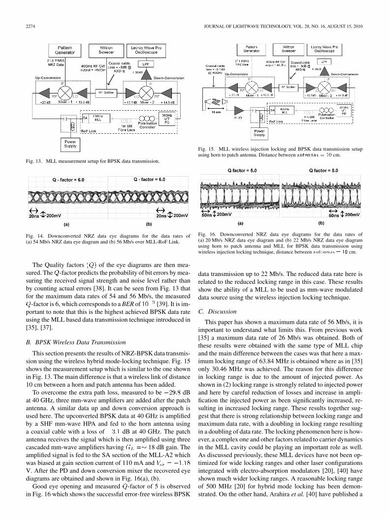
Fig. 15. MLL wireless injection locking and BPSK data transmission setupusing horn to patch antenna. Distance between �������� � �� cm.
Fig. 16. Downconverted NRZ data eye diagrams for the data rates of(a) 20 Mb/s NRZ data eye diagram and (b) 22 Mb/s NRZ data eye diagramusing horn to patch antenna and MLL for BPSK data transmission usingwireless injection locking technique, distance between �������� � �� cm.
data transmission up to 22 Mb/s. The reduced data rate here isrelated to the reduced locking range in this case. These resultsshow the ability of a MLL to be used as mm-wave modulateddata source using the wireless injection locking technique.
C. Discussion
This paper has shown a maximum data rate of 56 Mb/s, it isimportant to understand what limits this. From previous work[35] a maximum data rate of 26 Mb/s was obtained. Both ofthese results were obtained with the same type of MLL chipand the main difference between the cases was that here a max-imum locking range of 63.84 MHz is obtained where as in [35]only 30.46 MHz was achieved. The reason for this differencein locking range is due to the amount of injected power. Asshown in (2) locking range is strongly related to injected powerand here by careful reduction of losses and increase in ampli-fication the injected power as been significantly increased, re-sulting in increased locking range. These results together sug-gest that there is strong relationship between locking range andmaximum data rate, with a doubling in locking range resultingin a doubling of data rate. The locking phenomenon here is how-ever, a complex one and other factors related to carrier dynamicsin the MLL cavity could be playing an important role as well.As discussed previously, these MLL devices have not been op-timized for wide locking ranges and other laser configurationsintegrated with electro-absorption modulators [20], [40] haveshown much wider locking ranges. A reasonable locking rangeof 500 MHz [20] for hybrid mode locking has been demon-strated. On the other hand, Arahira et al. [40] have published a

KHAWAJA AND CRYAN: WIRELESS HYBRID MODE LOCKED LASERS 2275
much larger locking range of 1.9 GHz for 40-GHz/1.55 m ac-tive MLL. However, the 1.9 GHz locking range devices are notcommercially available. It is however believed that specificallydesigned MLL devices integrated with SA sections can producewider locking ranges and hence higher modulation bandwidths.
This paper has concentrated on device characterisation andwireless transmission of data using short lengths of SMF2 m. Other workers have shown similar techniques [24], [41]and have included longer fibre lengths of between 50–400 mof SMF. In these injection locked modulation schemes therewill be a number of effects which will limit the fibre rangefor a given data rate and mm-wave carrier frequency includingsideband cancellation [11] and the laser spectral width. How-ever, the technique has been shown to work over 400 m ofSMF [24] and it is felt that for the envisaged applications ofin-building/campus wide pico-cellular systems it is likely thatthese fibre ranges will be sufficient.
The wireless data transmission results using MLLs shownhere are for a short range of 10 cm, realistic applicationswould be in the range 5–10 m range. It should be noted thatthe mm-wave output power at the PD does not have a simpledependence on the power injected in to the SA section. Thus,link gain calculations are more complex in this MLL-injectionlocked system. This is highlighted in Fig. 7 where the link gainincreases with decreasing input power to the SA section. It isexpected that specifically designed MLLs could have a muchwider locking range which could enable high data rate commu-nications in the 5–10 m range. The path loss for 5 m is 64.88dB at 40 GHz, an increase of 35.08 dB over the 10 cm caseshown here. It is felt that this extra loss could be compensatedby increased amplification in the system and also by the use ofbeamforming techniques to produce high gain beams for theuplink. For example in [41] a range of 10 m was achieved byusing high gain amplifiers and horm antennas. Interestingly,here it also possible to use a semiconductor optical amplifier toboost the output optical power of the MLL. If this device wasmonolithically integrated with the MLL, the cost implicationswould not be that great. One further solution would be themonolithic integration of a MLL with a RF amplifier andantenna, this will be explored in the future work.
V. CONCLUSION
This paper has shown what is believed to be the first exampleof simultaneous wireless injection locking of a MLL and 22Mb/s NRZ BPSK data transmission using a wireless connec-tion to the SA section. It describes the factors which limit themaximum data rate which can be achieved using MLL injec-tion locking and a maximum data rate of 56 Mb/s is achievedfor a locking range of 63.84 MHz. This paper has shown amodular integration approach using K-connector fixtures. Fu-ture work will combine the MLL, amplifiers and planar an-tenna on the same mount to create a very compact module.This is a stepping stone to full monolithic integration of MLLswith antennas which could dramatically reduce the costs of suchradio-over-fiber systems.
REFERENCES
[1] P. F. M. Smulders, “60 GHz radio: Prospects and future directions,” inProc. Symp. IEEE Benelux Chapter on Communications and VehicularTechnol., Eindhoven, 2003, pp. 1–8.
[2] R. W. Ridgway and D. W. Nippa, “Generation and modulation of a94-GHz signal using electro-optic modulators,” IEEE Photonics Tech.Lett., vol. 20, no. 8, pp. 653–655, Apr. 2008.
[3] WiHD [Online]. Available: http://www.wirelesshd.org[4] Z. Ahmed et al., “37-GHz fiber-wireless system for distribution of
broadband signals,” IEEE Trans. Microw. Theory Tech., vol. 45, no.8, pp. 1431–1435, Aug. 1997.
[5] C. H. Cox, III, Analog Optical Links. Cambridge, U.K.: CambridgeUniv., 2004.
[6] M. Sauer, K. Kojucharow, H. Kaluzni, D. Sommer, W. Nowak, and A.Finger, “Radio-optical system design and transmission experiments fora mobile broadband communications system at 60 GHz,” Wireless Pers.Commun.—Special Issue Radio Over Fibre-Systems, Technologies Ap-plications, vol. 14, no. 2, pp. 147–163, Aug. 2000.
[7] A. J. Seeds, “Microwave photonics,” IEEE Trans. Microw. TheoryTech., vol. 50, no. 3, pp. 877–887, Mar. 2002.
[8] M. Sauer, A. Kobyakov, and J. George, “Radio over fiber for pico-cellular network architectures,” J. Lightw. Tech., vol. 25, no. 11, pp.3301–3319, Nov. 2007.
[9] J. K. White, C. Blaauw, P. Firth, and P. Aukland, “85 C investigation ofuncooled 10-Gb/s directly modulated InGaAsP RWG GC-DFB lasers,”IEEE Photonics Technol. Lett., vol. 13, no. 8, pp. 773–775, Aug. 2001.
[10] K.-S. Choi et al., “System-on-packaging with electroabsorption modu-lator for a 60-GHz band radio-over-fiber link,” IEEE Trans. Adv. Pack-aging, vol. 31, no. 1, pp. 63–169, Feb. 2008.
[11] G. H. Smith, D. Novak, and Z. Ahmed, “Overcoming chromatic-disper-sion effects in fiber-wireless systems incorporating external modula-tors,” IEEE Trans. Microw. Theory Tech., vol. 45, no. 8, pp. 1410–1415,Aug. 1997.
[12] K. Yonenaga and N. Takachio, “A fiber chromatic dispersion compen-sation technique with an optical SSB transmission in optical homo-dyne detection systems,” IEEE Photon. Technol. Lett., vol. 5, no. 8, pp.949–951, Aug. 1993.
[13] M. Attygalle, C. Lin, G. J. Pendock, A. Nirmalathas, and G. Edvell,“Transmission improvement in fiber wireless links using fiber Bragggratings,” IEEE Photon. Tech. Lett., vol. 17, no. 1, pp. 190–192, 2005.
[14] J. Li, T.-G. Ning, L. Pei, and C. H. Qi, “Scheme for a high-capacity 60GHz radio-over-fiber transmission system,” IEEE/OSA J. Opt. Comm.Netw., vol. 1, no. 4, pp. 324–330, Sep. 2009.
[15] G. Qi, J. Yao, J. Seregelyi, S. Paquet, and C. Bélisle, “Optical gener-ation and distribution of continuously tunable millimeter-wave signalsusing an optical phase modulator,” J. Lightw. Technol., vol. 23, no. 9,pp. 2687–2694, Sep. 2005.
[16] P. Shen, J. James, N. J. Gomes, P. G. Huggard, and B. N. Ellison,“Low-cost, continuously tunable, millimeter-wave photonic LO gen-eration using optical phase modulation and DWDM filters,” IEEEPhoton. Technol. Lett., vol. 20, no. 23, pp. 1986–1988, Dec. 2008.
[17] T. Taniguchi et al., “Full-duplex 1.0 Gbit/s data transmission over 60GHz radio-on-fiber access system based on the loop-back optical het-erodyne technique,” J. Lightw. Technol., vol. 26, no. 13, pp. 1765–1776,Jul. 2008.
[18] M.-K. Hong, Y.-Y. Won, and S.-K. Han, “Gigabit optical access linkfor simultaneous wired and wireless signal transmission based on dualparallel injection-locked Fabry-Pérot laser diodes,” J. Lightw. Technol.,vol. 26, no. 15, pp. 2725–2731, Aug. 2008.
[19] L. Noel, D. Wake, D. G. Moodie, D. D. Marcenac, L. D. Westbrook,and D. Nesset, “Novel techniques for high-capacity 60-GHz fiber-radiotransmission systems,” IEEE Trans. Microw. Theory Tech., vol. 45, no.8, pp. 1416–1423, Aug. 1997.
[20] R. Kaiser and B. Huttl, “Monolithic 40-GHz mode-locked MQW DBRlasers for high-speed optical communication systems,” IEEE J. Sel.Topics In Quantum Elec, vol. 13, no. 1, pp. 125–135, Jan./Feb. 2007.
[21] B. Huettl, R. Kaiser, M. Kroh, C. Schubert, G. Jacumeit, and H. Hei-drich, “Optical 40 GHz pulse-source module based on a monolithicallyintegrated mode locked DBR laser,” SPIE Proc., Optoelec. Materialsand Devices for Opt. Comms., vol. 6020, pp. 479–487, 2005.
[22] S. Arahira and Y. Ogawa, “Polarization-insensitive all-optical160-Gb/s clock recovery with a monolithic passively mode-lockedlaser diode in polarization-diversity configuration,” IEEE J. QuantumElectron., vol. 43, no. 12, pp. 1204–1210, Dec. 2007.

2276 JOURNAL OF LIGHTWAVE TECHNOLOGY, VOL. 28, NO. 16, AUGUST 15, 2010
[23] B. A. Khawaja and M. J. Cryan, “Study of millimeter wave phase shiftin 40 GHz hybrid mode locked lasers,” IEEE Microw. Wireless Comp.Lett., vol. 19, no. 3, pp. 182–184, Mar. 2009.
[24] J. B. Georges et al., “Optical transmission of narrowband mil-limeter-wave signals by resonant modulation of monolithic semicon-ductor lasers,” IEEE Photon. Technol. Lett., vol. 6, no. 4, pp. 568–570,Apr. 1994.
[25] J. B. Georges, D. M. Cutrer, M.-H. Kiang, and K. Y. Lau, “Multi-channel millimeter wave subcarrier transmission by resonant modula-tion of monolithic semiconductor lasers,” IEEE Photon. Technol. Lett,vol. 7, no. 4, pp. 431–433, Apr. 1995.
[26] T. Ohno, F. Nakajima, T. Furuta, and H. Ito, “A 240-GHz active mod-elocked laser diode for ultra-broadband fiber-radio transmission sys-tems,” in Tech. Dig. Opt. Fiber Comm. Conf., Mar. 2005, vol. 6, pp. 3–.
[27] V. Sittakul and M. J. Cryan, “A fully bidirectional 2.4-GHz wireless-over-fiber system using photonic active integrated antennas (PhAIAs),”J. Lightw. Technol., vol. 25, no. 11, pp. 3358–3365, Nov. 2007.
[28] V. Sittakul and M. J. Cryan, “A 2.4-GHz wireless-over-fibre systemusing photonic active integrated antennas (PhAIAs) and losslessmatching circuits,” J. Lightw. Technol., vol. 27, no. 14, pp. 2724–2731,Jul. 2009.
[29] A. Hirata, H. Ishii, and T. Nagatsuma, “Design and characteriza-tion of a 120-GHz millimeter-wave antenna for integrated photonictransmitters,” IEEE Trans. Microw. Theory Tech., vol. 49, no. 11, pp.2157–2162, Nov. 2001.
[30] U. Gliese, S. Nørskov, and T. N. Nielsen, “Chromatic dispersion infiber-optic microwave and millimeter-wave links,” IEEE Trans. Mi-crow. Theory Tech., vol. 44, pp. 1716–1724, Oct. 1996.
[31] R. Adler, “A study of locking phenomena in oscillators,” Proc. IEEE,vol. 61, pp. 1380–1385, Oct. 1973.
[32] A. E. Siegman, Lasers. Oxford, U.K.: Oxford University Press, 1986.[33] A. Zarroug, P. S. Hall, and M. J. Cryan, “Active antenna phase control
using subharmonic locking,” IEEE Electron. Lett., vol. 31, no. 11, pp.842–843, May 1995.
[34] B. Khawaja, I. Djordjevic, and M. Cryan, “A millimeter wave phaseshifter using a wireless hybrid mode locked laser,” in Proc. OFC, SanDiego, CA, Mar. 22–26, 2009, Paper OTuM5.
[35] B. A. Khawaja and M. J. Cryan, “A wireless hybrid mode locked laserfor low cost millimetre wave radio-over-fiber systems,” in Proc. Int.Top. Meeting Microwave Photonics 2009, Valencia, Spain, Oct. 2009,pp. 1–4.
[36] O. Wada, T. Sanada, and T. Sakurai, “Monolithic integration of an Al-GaAs/GaAs DH LED with a GaAs FET driver,” IEEE Electron Dev.Lett., vol. 3, no. 10, pp. 305–307, Oct. 1982.
[37] B. A. Khawaja and M. J. Cryan, “A hybrid mode locked laser as mil-limetre wave modulated data source for radio-over-fiber systems,” inProc. Summer Topical Meeting, 2009. LEOSST’09. IEEE/LEOS, New-port Beach, CA, Jul. 20–22, 2009, pp. 67–68.
[38] T. Ismail, C. P. Liu, J. E. Mitchell, and A. J. Seeds, “Transmissionof Gb/s DPSK millimeter-wave wireless data over fiber using low-cost uncooled devices with remote 40-GHz local oscillator delivery,”J. Lightw. Technol., vol. 26, no. 21, pp. 3490–3496, Nov. 2008.
[39] I. P. Kaminow and T. Li, Optical Fiber Telecommunications IV: Sys-tems and Impairment. New York: Academic, 2002, pp. 174–.
[40] S. Arahira and Y. Ogawa, “40 GHz actively mode-locked distributedBragg reflector laser diode module with an impedance-matching circuitfor efficient RF signal injection,” Jpn. J. Appl. Phys., vol. 43, no. 4B,pp. 1960–1964, 2004.
[41] F. Lecoche, E. Tanguy, B. Charbonnier, H. Li, F. van Dijk, A. Enard, F.Blache, M. Goix, and F. Mallécot, “Transmission quality measurementof two types of 60 GHz millimeter-wave generation and distributionsystems,” J. Lightw. Technol., vol. 27, no. 23, pp. 5469–5474, Dec.2009.
Bilal A. Khawaja was born in Karachi, Pakistan, inAugust 1980. He received the B.Sc. (computer en-gineering) degree from Sir Syed University of Engi-neering and Technology, Karachi, Pakistan, in 2002and the M.Sc. degree in communication engineeringand signal processing from University of Plymouth,Plymouth, U.K., in 2005.
He worked as a software engineer from 2003 to2004 in Simcon International (Pvt.) Ltd. He has beenworking towards the Ph.D. degree at the Universityof Bristol, Bristol, U.K., since 2006. His research in-
terests are in next generation radio-over-fibre systems and mode-locked lasers.
Martin J. Cryan received the B.Eng. degree inelectronic engineering from the University of Leeds,U.K., in 1986 and then worked in industry for fiveyears as a microwave design engineer. In 1995 hereceived the Ph.D. degree from the University ofBath, U.K., for work on GaAs MMIC design.
From 1994 to 1997 he was a Researcher at theUniversity of Birmingham, U.K., where he workedon active integrated antennas. From 1997 to 1999he was a European Union Training and Mobilityof Researchers research fellow working at the
University of Perugia, Italy on the design and simulation of quasi-opticalmultipliers using the Lumped—Element FDTD method. From 2000 to 2002 hewas a Research Associate at the University of Bristol, U.K., working on hybridelectromagnetic methods for EMC problems in optical transceivers and FDTDanalysis of photonic crystals. He was appointed as a lecturer in the departmentof Electrical and Electronic Engineering at the University of Bristol in 2002and was made Senior Lecturer in 2007. He has published 39 journal and morethan 120 conference papers (11 Invited), in the areas of fabrication, modellingand measurement of photonic crystal based devices, radio-over-fibre, activeintegrated antennas, FDTD analysis and MMIC design.