Embed Size (px)
Citation preview
WIRELESS ELECTRICITY
A SEMINAR REPORT
Submitted by
PATEL DHARMESH N. (090230111042)
PATEL SONESH R. (090230111044)
PATEL SHYAMAL B. (090230111118)
BHATT JIGNESH S. (090230111021)
In fulfillment for the award of the degree
of
BACHELOR OF ENGINEERING
in
Electronics and Communication Engineering
Government Engineering College of Surat
Gujarat Technological University, Ahmadabad
December,2012

Government Engineering College , Surat
Electronics and communication Engineering Department
2012
CERTIFICATE
Date: / /2012
This is to certify that the dissertation entitled “WIRELESS
ELECTRICITY” has been carried out by PATEL DHARMESH
N.(090230111042),PATEL SONESH R.(090230111044),PATEL
SHYAMAL B.(090230111118),BHATT JIGNESH
S.(090230111021) under my guidance in fulfillment of the degree
of Bachelor of Engineering in ELECTRONICS AND
COMMUNICATION ENGINEERING 7th
semester of Gujarat
Technological University, Ahmadabad during the academic year
2012-13.
Guide:
Prof. Avani A. Vithalani
Head of Department
Prof. P. S. GOSAI

i
ACKNOWLEDGEMENT
The present report is the work carried out during 4th
year under the supervision of Prof. Avani
A. Vithalani in Electronics and communication engineering department at Government
Engineering college, Surat.
Keeping in mind, first of all we want to thank our Government Engineering College
(Electronics and communication Engineering Department) for providing us such a great
atmosphere around us which encourages every student to work to their peak level. Special
thanks to our H.O.D of Electronics and communication Engineering department
Prof. Avani A. Vithalani for their immense support, for their precious guidance and moral
support which is beyond any comparison.
All our team members and our Professor have played significant role as moral boosters and
have extended all possible help and co-operation. We expressed sincere gratitude to them.
Last but not the least we are thankful to our parents who help us financially when Were
quired and encourage us to get great achievements in our life.
Thank you all.

ii
ABSTRACT
The objective of this technical report is to provide electrical energy to
remote objects without wires. Wireless energy transfer also known as wireless
energy transmission is the process that takes place in any system where
electromagnetic energy is transmitted from a power source to an electrical load,
without interconnecting wires. Wireless transmission is employed in cases
where interconnecting wires are inconvenient, hazardous, or impossible.
The principle of wireless electricity works on the principle of using
coupled resonant objects for the transfer of electricity to objects without the use
of any wires. A witricity system consists of a witricity transmitter and another
device called the receiver.
The receiver works on the same principle as radio receivers where the
device has to be in the range of the transmitter. It is with the help of resonant
magnetic fields that witricity produces electricity, while reducing the wastage of
power. The present report on witricity aims at power transmissions in the range
of 100 watts. May be the products using WiTricity in future might be called
Witric or Witric's.

iii
LIST OF FIGURES
Figure No Figure Description Page No
Figure 2.1 A time-changing current in coil 1 causes a 3
time-changing magnetic flux through coil
2 which induces a time-changing current in
that coil.
Figure 2.2 A schematic rectenna diagram. 3
Figure 2.3 In electron in the HOMO is excited by a 5
photon .The electron leaves the molecule
thus generating an ion.
Figure 2.4 Conduction by means of ionized air molecules. 5
Figure 2.5 A demonstration of power transmission through 6
evanescent wave coupling.
Figure 3.1 block diagram. 7
Figure 3.2 Amplifier 8
Figure 3.3 oscillator 10
Figure.3.4 Transmitting and receiving coil. 13
Figure 3.5 voltage rectifier 13
Figure 4.1 The CET desktop application showing activated 16
coils powering the devices placed on table
Figure 4.2 wireless powered and controlled laptop screen 17
iv
Figure No Figure Description Page No
Figure 5.1 parallel configuration configuration. 21
Figure 5.2 characteristic of parallel configuration. 22
Figure 5.3 perpendicular configuration. 23
Figure 5.4 characteristic perpendicular configuration. 24
Figure 6.1 Schematic setup of the Standby saver. When 25
the latching relay switches due to a power pulse
received by the rectenna, the TV is connected to
outlet power and turns on.

v
LIST OF TABLE
Table No Table Description Page No
Table 3.1 Transmitting & Receiving 12
Elements
Table 6.1 SAR limits for unaware exposure of the 29
general public, according to several
international organizations.

vi
TABLE OF COTENTS
Acknowledgement i
Abstract ii
List of figures iii
List of tables v
Table of content vi
Chapter : 1 Introduction (page 1 start )
Chapter : 2 Theory (page 2 start)
2.1 introduction 2
2.2 radio waves 3
2.3 light 4
2.4 Electrical Conduction 4
2.5 Evanescent Wave Coupling 5
Chapter : 3 System design(page 7 start )
3.1 Oscillator 7
3.1.1 Design 8
3.1.2 Design details 9
3.2 Power amplifier 10
3.2.1 Design 10
3.2.2 Design details 11
3.3Transmitting and receiving coil 11
3.3.1 Design 12
3.4 Voltage rectifier 13

vii
Chapter : 4 All applications (page 15 start )
4.1 Combination of wireless power and network 15
4.2Contactless Energy Transfer Desktop Application 15
4.3 Wireless powered LED bicycle lights 16
4.4 Wireless powered and controlled laptop screen 16
4.5 Applications using Powercast technology 17
4.6 Solar powered recharging backpack 18
4.7 Wireless audio speakers 18
4.8 Wireless powered vacuum cleaner 18
4.9 Wireless power-on function 19
Chapter : 5 Result and measurement (page 20 start )
Chapter : 6 Standby Saver (page 25 start )
6.1 Technological design 25
6.2 Environmental analysis 27
6.3 Health hazards 27
6.4 Economic aspects 30
Chapter : 7 Conclusion and future work (page 31 start )
Chapter : 8 Reference (page 32 start )
8.1Original MIT paper 32
8.2 Link to the project 32

Wireless electricity 2012
Government Engineering Collage ,surat Page 1
Chapter 1: Introduction
Wireless power transfer may seem like science fiction, but the idea is more than 100 years
old. Around 1900 Nicola Tesla claimed to be able to radiate power over long distances
with minimum loss of power, took a patent and even got some industrial finance for trials.
These failed. Hundred years later, an electric toothbrush using Contactless inductive
charging device is a common commodity in many households. Even more recently new
breakthroughs are claimed to radiate enough energy from a power outlet to feed a nearby
low-voltage lamp or electronic device using radio- frequency radiation over a distance of
one meter. In this project, we came up with nine possible applications of wireless power
transfer. They were analyzed based on a list of criteria, and based on this, the feasibility
of the two best applications was investigated further. These criteria were:
• User-friendly, easy to use and easily standardized.
• Technologically possible to make.
• Economically feasible.
• Sustainable.
In chapter 2 of this report you will find the theory about the various ways of wireless power
transfer. In chapter 3, all applications we came up with are mentioned, and these applications
are analyzed and rated based on the criteria in chapter 4. Then in chapter 5 and 6, the two
selected applications are investigated more thoroughly. In on these applications is drawn, and
some recommendations are given.

Wireless electricity 2012
Government Engineering Collage ,surat Page 2
Chapter 2: Theory
There are different ways to achieve wireless power transfer from a power source to a
receiver. This chapter will discuss the basic theory behind several ways of wireless power
transfer.
2.1 Induction
When the magnetic flux through a circuit changes, an electromotive force (emf) and a
current are induced in the circuit. This effect is for example used in dynamos, electric
motors and transformers. The central principle behind electromagnetic induction is
Faraday’s law, which relates to the induced electromotive force (emf) in any closed
Loop including a closed circuit 1.Induction can be used as a means of wireless power
transfer. A changing current in one coil 1 creates an emf, which in turn induces a current
in a coil 2, as shown in Figure 2.1.
The coils are not in contact and in this way energy can very simply be transported over
short distances. This is used in for example an electric toothbrush charger. The short
distance that is required for induction is the largest drawback of this way of wireless
energy transfer, because it limits the applicability to very close-range situations 2.

Wireless electricity 2012
Government Engineering Collage ,surat Page 3
Figure 2.1: A time-changing current in coil 1 causes a time-changing magnetic flux through coil 2
which induces a time-changing current in that coil.
2.2 Radio Waves
The key component for wireless power transfer by radio waves is the rectenna. A
rectenna is a combination of a rectifying circuit and an antenna. The antenna receives the
electromagnetic power and the rectifying circuit converts it to DC electric power. A
schematic rectenna design is shown in Figure 2.2.
Figure 2.2: A schematic rectenna diagram.
A simple rectenna can be constructed from a Schottky diode 5 placed between the
antenna dipoles. The diode rectifies the current induced in the antenna by the

Wireless electricity 2012
Government Engineering Collage ,surat Page 4
microwaves. Schottky diodes are used because they have the lowest voltage drop and
highest speed and therefore waste the least amount of power due to conduction and
switching.
The amount of power that can be transferred is limited. For safety reasons, the transmitted
power is limited by regulations, for instance by the Federal Communications Commision
(FCC), and the received power is attenuated, mainly due to free-space path loss.
Furthermore, because portable devices have small dimensions, the rectenna should have
small dimensions as well. This results in a small
antenna area and, consequently, a low amount of received power. Because of these
limitations, wireless power transfer using radio waves is mainly suitable for low-power
applications, e.g. a low-power wireless sensor.
2.3 Light
Power delivery that starts with sunlight has many advantages such as sustainability and
the fact that the sun is present every day. However solar cells have limited efficiency and
sunlight is not available at night. An alternative is to generate artificial light, from a laser,
transmit it through air, and then convert it into electricity. New refinements are making
this alternative more attractive. NASA has demonstrated flight of a lightweight model
plane powered by laser beam, directed at a panel of infrared-sensitive photovoltaic cells
mounted on the bottom of the aircraft.
A theoretical setup consists of a laser (Light Amplification by Stimulated Emission of
Radiation) and a photovoltaic, or solar cell. First electricity is converted by the laser into
a laser beam, which consists of coherent radiation. Next this beam is pointed towards a
photovoltaic cell receiver, which in turn converts the received light energy back into
electricity. This is generally called “power beaming”. Both steps are not highly efficient
and also a direct line of sight between laser and the photovoltaic cells is required.
2.4 Electrical Conduction
Power is normally supplied by means of a conducting wire, where the conductive material
is a metal. In the case of wireless power supply through conduction, this conducting wire
is replaced by ionized air. Air is a good insulator and a high potential difference, called
the breakdown voltage, is required to generate a current. In the case of lightning this can
easily be 10.000 volts.
Wireless electricity 2012
Government Engineering Collage ,surat Page 5
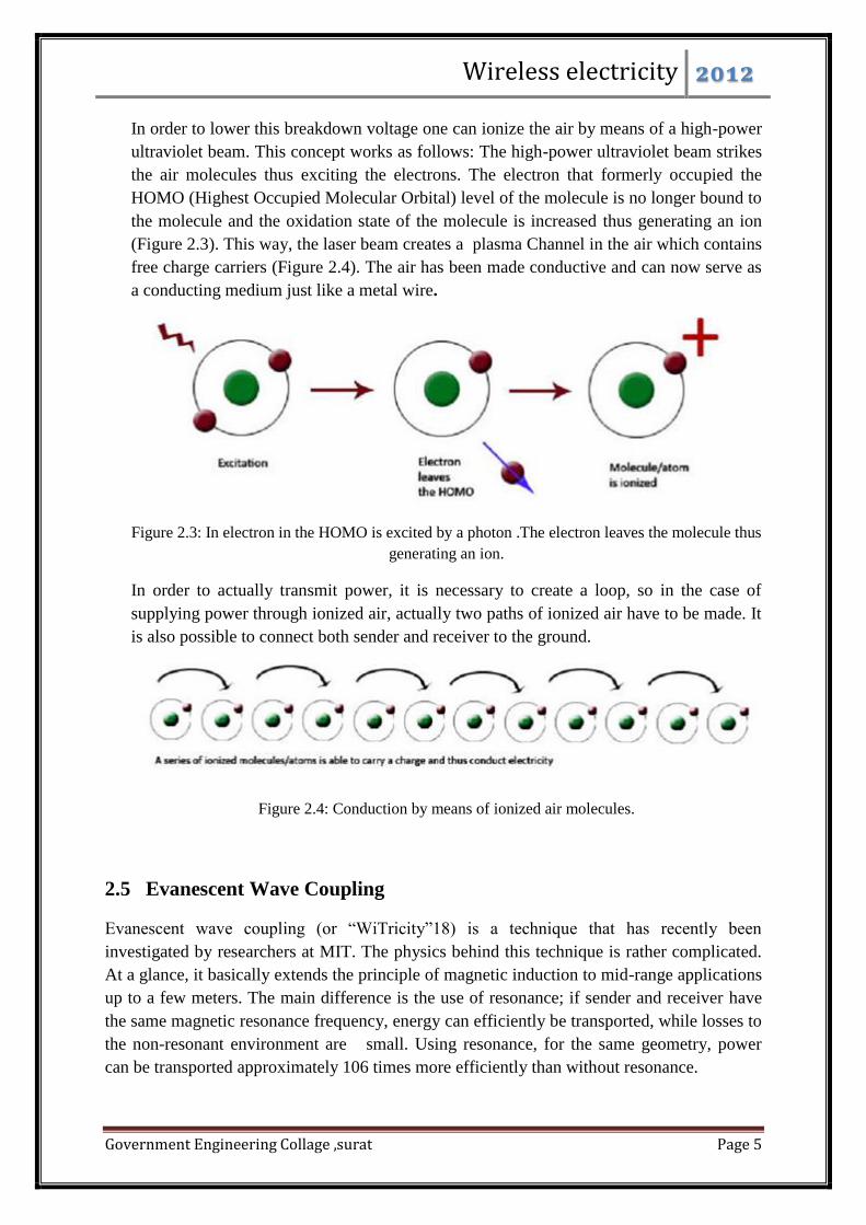
In order to lower this breakdown voltage one can ionize the air by means of a high-power
ultraviolet beam. This concept works as follows: The high-power ultraviolet beam strikes
the air molecules thus exciting the electrons. The electron that formerly occupied the
HOMO (Highest Occupied Molecular Orbital) level of the molecule is no longer bound to
the molecule and the oxidation state of the molecule is increased thus generating an ion
(Figure 2.3). This way, the laser beam creates a plasma Channel in the air which contains
free charge carriers (Figure 2.4). The air has been made conductive and can now serve as
a conducting medium just like a metal wire.
Figure 2.3: In electron in the HOMO is excited by a photon .The electron leaves the molecule thus
generating an ion.
In order to actually transmit power, it is necessary to create a loop, so in the case of
supplying power through ionized air, actually two paths of ionized air have to be made. It
is also possible to connect both sender and receiver to the ground.
Figure 2.4: Conduction by means of ionized air molecules.
2.5 Evanescent Wave Coupling
Evanescent wave coupling (or “WiTricity”18) is a technique that has recently been
investigated by researchers at MIT. The physics behind this technique is rather complicated.
At a glance, it basically extends the principle of magnetic induction to mid-range applications
up to a few meters. The main difference is the use of resonance; if sender and receiver have
the same magnetic resonance frequency, energy can efficiently be transported, while losses to
the non-resonant environment are small. Using resonance, for the same geometry, power
can be transported approximately 106 times more efficiently than without resonance.

Wireless electricity 2012
Government Engineering Collage ,surat Page 6
The experimental setup used by the MIT researchers is shown in Figure 5. The coils can be
compared to antennas; the electric and magnetic fields produced by antennas can generally be
divided into the near field, which is dominant at close ranges, and the far field. The far field,
responsible for electromagnetic waves, radiates energy into the environment. The near field
does not radiate, so no energy is lost, except when the sender and receiver have the same
resonance frequency. In that case energy is transported from the sender to the receiver. The
main achievement of the MIT team is to have figured out
how to fine tune the system so that the near field extends to distances of a few meters,
simultaneously limiting the power radiated through the far field.
Figure 2.5: A demonstration of power transmission through evanescent wave coupling.
One of the benefits is that most common materials do not interact with magnetic fields, so
obstructing objects do not have much influence. This also goes for human tissue and
therefore health risks are low. The coils shown above are too large for applications in i.e. a
cell phone, but the receiving coil can be made smaller. The researchers state that the
transmitted power can be kept constant, if the size of the sending coil is increased to keep the
product of the sizes of both coils equal. The efficiency of the above setup is around 40 to
50% for wireless power transfer over 2 meters. However, the efficiency from power outlet to
light bulb was 15%, because a ery inefficient component (Colpitts oscillator) was used.
Wireless electricity 2012
Government Engineering Collage ,surat Page 7
Chapter 3: SYSTEM DESIGN
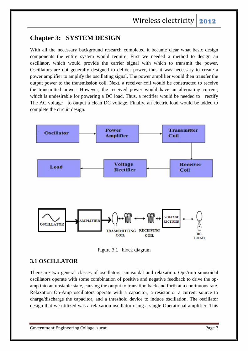
With all the necessary background research completed it became clear what basic design
components the entire system would require. First we needed a method to design an
oscillator, which would provide the carrier signal with which to transmit the power.
Oscillators are not generally designed to deliver power, thus it was necessary to create a
power amplifier to amplify the oscillating signal. The power amplifier would then transfer the
output power to the transmission coil. Next, a receiver coil would be constructed to receive
the transmitted power. However, the received power would have an alternating current,
which is undesirable for powering a DC load. Thus, a rectifier would be needed to rectify
The AC voltage to output a clean DC voltage. Finally, an electric load would be added to
complete the circuit design.
Figure 3.1 block diagram
3.1 OSCILLATOR
There are two general classes of oscillators: sinusoidal and relaxation. Op-Amp sinusoidal
oscillators operate with some combination of positive and negative feedback to drive the op-
amp into an unstable state, causing the output to transition back and forth at a continuous rate.
Relaxation Op-Amp oscillators operate with a capacitor, a resistor or a current source to
charge/discharge the capacitor, and a threshold device to induce oscillation. The oscillator
design that we utilized was a relaxation oscillator using a single Operational amplifier. This
Wireless electricity 2012
Government Engineering Collage ,surat Page 8
oscillator was a Square Wave Generator and could be classified in the category as an astable
multivibrator.
3.1.1 DESIGN
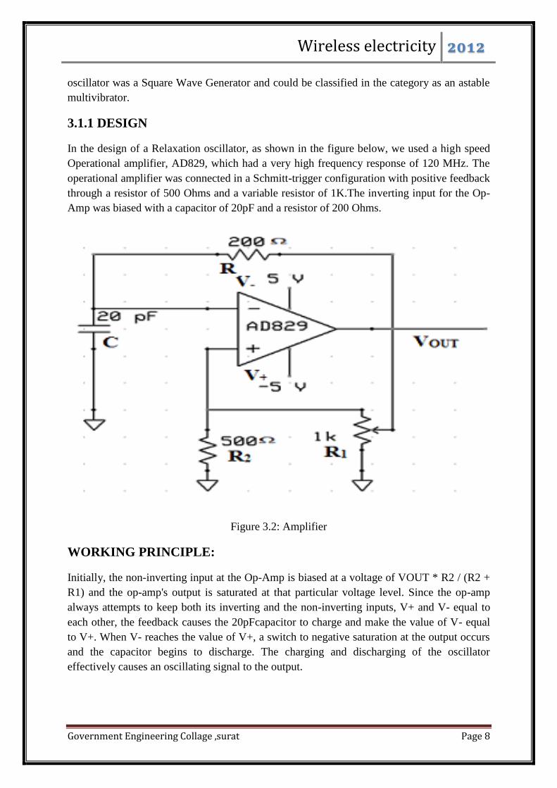
In the design of a Relaxation oscillator, as shown in the figure below, we used a high speed
Operational amplifier, AD829, which had a very high frequency response of 120 MHz. The
operational amplifier was connected in a Schmitt-trigger configuration with positive feedback
through a resistor of 500 Ohms and a variable resistor of 1K.The inverting input for the Op-
Amp was biased with a capacitor of 20pF and a resistor of 200 Ohms.
Figure 3.2: Amplifier
WORKING PRINCIPLE:
Initially, the non-inverting input at the Op-Amp is biased at a voltage of VOUT * R2 / (R2 +
R1) and the op-amp's output is saturated at that particular voltage level. Since the op-amp
always attempts to keep both its inverting and the non-inverting inputs, V+ and V- equal to
each other, the feedback causes the 20pFcapacitor to charge and make the value of V- equal
to V+. When V- reaches the value of V+, a switch to negative saturation at the output occurs
and the capacitor begins to discharge. The charging and discharging of the oscillator
effectively causes an oscillating signal to the output.

Wireless electricity 2012
Government Engineering Collage ,surat Page 9
The general equation for charging a capacitor is given by:
In this case, V is -VOUT, and if the voltage at V+ is called VOUT, q0 becomes CVOUT. The
charging equation then becomes
When q gets to -VOUT, another switch will occur. This time it is half the period of the square
wave. Therefore:
Solving for T gives:
The frequency of oscillation can be determined by. In our case, the variable resistor R1 could
be varied using a 1K pot which was able to tune the frequency from 1.6 MHz to 10.3 MHz.
3.1.2 DESIGN DETAILS
The challenges encountered during the design of the oscillator were the selection of the
oscillator design and the Op-Amp chip required to
produce a stable and symmetrical oscillating signal. We had experimented with IC Logic
chips and low frequency response Op-Amp chips for the design of the oscillator. However,
the oscillation signal output from these circuit configurations was not stable or symmetrical.
We also initially had problems with distortion of the signal by the unstable power supply
from the PCB board and other extraneous noise at high frequencies. We dealt with this
problem by neatly laying out the relaxation oscillator circuit using shorter wires and the
placing two decoupling capacitors of one microfarads each between the positive and negative
power supply to the ground.

Wireless electricity 2012
Government Engineering Collage ,surat Page 10
3.2 POWER AMPLIFIER
In order to generate the maximum amount of flux which would induce the largest voltage on
the receiving coil, a large amount of current must be transferred into the transmitting coil.
The oscillator was not capable of supplying the necessary current, thus the output signal from
the oscillator was passed through a power amplifier to produce the necessary current. The key
design aspect of the power amplifier was to generate enough current while producing a clean
output signal without large harmonic distortions. For this purpose, we utilized a simple
switch-mode amplifier design whose design aspects are described below.
3.2.1 DESIGN
The main idea behind the switch-mode Power Amplifier technology is to operate a
MOSFET in saturation so that either voltage or current is switched on and off. The figure
below shows the circuit diagram of the switch-mode power amplifier.
Figure 3.3:oscillator
Our switch-mode design consisted of a MOSFET IRF 510, which when turned on allowed
large current from the DC power supply to flow through the resistor of 50 Ohms and
through the transmitting antenna to transfer current from the power supply through the
transmitting coil. The large current from the transmitting coil was able to generate a large
flux to induce a high voltage in the receiving coil. The current and voltage required to drive
the gate of the MOSFET IRF 510 was supplied by the MOSFET IRF 640 whose gate was
Wireless electricity 2012
Government Engineering Collage ,surat Page 11
driven by the input signal from a Hewlett Packard signal generator. The maximum voltage
when the coils were tuned at resonance was recorded to be around 102.3V.
3.2.2 DESIGN DETAILS
Since our single op-amp relaxation oscillator was using an AD 829 chip, it was not able to
source enough current to drive the Mosfet IRF 510 or control the amplitude of the output
signal. For this reason, we employed the Hewlett Packard 3310A Function Generator as our
oscillator. The signal generator was capable of supplying current and voltage required for
driving the gate of the IRF640. Furthermore, using the signal generator, we were also able to
set the DC bias voltage and tune the output voltage to get maximum voltage out.
The major challenge while designing the power amplifier circuit was to drive the gate of the
Mosfet IRF 510 to switch the Mosfet on. Our initial approach was to design a class D
amplifier to drive a H-Bridge3 configuration (which meant driving 4 IRF 510 Mosfet) for an
efficient power amplification using a single positive power supply. The H-Bridge 4 required
two digital signals that were 180 degrees out of phase with a small dead-time in between the
signals. The whole second week we were working on trying to generate these signals as
inputs to the H-bridge. In generating these signals, we encountered problems with our
comparator chips to output noise free digital signals at high frequency (5 MHz range). Using
2 high speed comparators, LT1016, and introducing terminating resistances (68 Ohm) in
series to the output, we were able to output digital signals 180 out of phase with a small dead
time for the input to the H-Bridge.
However, the signal output from the comparators as can be seen from the image above was
unable to turn the Mosfet IRF 510 on. The comparator could not source enough current to
drive the gate of the Mosfet to turn on at a frequency range of around 5 MHz.
3.3 TRANSMITTER AND RECEIVER COILS
The transmitter and receiver circuit combined is called the coupling circuit. It is the heart of
the entire system as the actual wireless power transfer is carried out here. The efficiency of
the coupling circuit determines the amount of power available for the receiver system.
3.3.1. DESIGN
The transmitter and receiver coils were designed by former Cornell students, Lucas Jorgensen
and Adam Culberson. The coils had a resonant frequency of 4.8 – 5.3 MHz, which could be
tuned with our oscillator (later a signal generator) to get to the resonance frequency of the
coils. The basic configuration of the design can be seen from the table and the image below.

Wireless electricity 2012
Government Engineering Collage ,surat Page 12
Table 3.1 : transmitting and receiving elements
Figure.3.4: Transmitting and receiving coil.
3.4 VOLTAGE RECTIFIER:
A rectifier would be needed to rectify the AC voltage received from the receiver coil to drive
a DC load. it has some specified DC component is a Full Wave Bridge Rectifier. This type of
single phase rectifier uses four individual rectifying diodes connected in a closed loop
"bridge" configuration to produce the desired output. The smoothing capacitor connected to

Wireless electricity 2012
Government Engineering Collage ,surat Page 13
the bridge circuit converts the full-wave rippled output of the rectifier into a smooth DC
output voltage.
Figure 3.5: voltage rectifier
Since the diodes had to rectify AC signals of Megahertz frequencies, fast signal diodes,
1N914B, had to be used for the bridge circuit. However we did not implement this circuit
with our final setup as we did not drive a DC load with our setup.

Wireless electricity 2012
Government Engineering Collage ,surat Page 14
Chapter 4. All applications
In this chapter, possible applications using wireless power supply are introduced. The
applications came up during a brainstorm session. Powercast is an application that is already
being developed commercially. The contactless energy desktop application of is based on
research currently conducted at Eindhoven University of Technology. All other applications
are ideas of our own.
4.1 Combination of wireless power and network
Wireless networks eliminate cables by using radio waves to transfer the data from computer
to router. However, the battery life of a laptop is still limited, so there still is the need of
carrying a cable for powering the laptop itself. It would be nice to combine these two into
one: using the radio waves of a wireless network, not only for internet but also for powering
the laptop itself.
4.2 Contactless Energy Transfer Desktop Application
Contactless Energy Transfer (CET) is the process in which electrical energy is transferred
between two or more electrical devices through inductive coupling. The CET desktop
application is a new development in the area of wireless power transmission, where a table
with embedded “power transmitting coils” powers and recharges different electronic devices,
which normally need to be charged by Plug & Socket connectors, like cellular phones, music
players and laptops . This is done by simply placing them on top of the desk.
The CET desktop uses a matrix of hexagon spiral windings embedded underneath its surface,
to transfer power to CET enabled consumer electronics devices placed on the wooden or
plastic table. When electronic devices fitted with power receiving coils are placed on the
table, the increase in electromagnetic coupling between primary and secondary coils, allows
power to be transmitted from the desktop to the devices. To improve efficiency and limit
stray magnetic fields, clusters of only three primary coils, located closest to the receiving
devices, are excited. The coils are excited with out-of-phase currents to further reduce stray
magnetic fields. The power transfer efficiency is not constant but varies throughout the
surface of the table, because the magnetic field of a coil is not homogeneous.

Wireless electricity 2012
Government Engineering Collage ,surat Page 15
Figure 4.1: The CET desktop application showing activated coils powering the devices placed on
table
4.3 Wireless powered LED bicycle lights
Removable LED lights are used worldwide on bicycles that do not have wired lighting. The
advantage of these lights is that they do not require a dynamo to power them, because they
use batteries. However, the batteries can unexpectedly run out of power and need to be
replaced often which is not environmentally friendly. As an alternative a new application,
using a dynamo to wirelessly power LED lights using radio waves, is introduced. Because
this is one of the applications that were chosen for further research, more information can be
found in chapter 6: Wireless Bicycle Lights.
4.4 Wireless powered and controlled laptop screen
A common defect in laptops is that the cable that connects the display is damaged causing the
screen to flicker or to go black. Normally this is caused by wear and tear and it has the
tendency to occur outside the laptop’s warranty. One way to avoid the cable to break is to
have no cable at all. As a new application the wireless powering and controlling of a laptop
screen is introduced.

Wireless electricity 2012
Government Engineering Collage ,surat Page 16
Figure 4.2: wireless powered and controlled laptop screen
Since the display is attached to the rest of the laptop via a hinge, it is very close to the bottom
part of the laptop. Powering of the display can be easily achieved using mutual induction, a
principle that has been very well proven to work for all kind of applications. Controlling the
contents on the screen can be achieved using a radio signal. This can be done just like with
wireless internet on for instance the 2.45 GHz band.
The application would work the same way as a power transformer: a changing current in the
first circuit creates a changing magnetic field; in turn, this magnetic field induces a changing
voltage in the second circuit If the primary circuit (in the laptop bottom part) and secondary
circuit (in the display) are very close, which will be the case for this application, a very high
efficiency can be achieved. Everything inside a laptop is DC powered. To be able to use
mutual inductance, this DC must be inverted to AC first. There are already small inverters
around to be able to cope with the 8-10 Watts power requirement 25 of a laptop display26,
27. Depending on the efficiency of the inverter, it could be so that not much extra power is
consumed powering a wireless display, compared to powering a wired display.
4.5 Applications using Powercast technology
Powercast is a company that has invented a way to wirelessly transfer energy using radio
waves to a so called harvester module. The modules are made to power small devices such as
cell phones, lighting, remote controls, sensors and toys. Recently, the first commercial
product using Powercast was released, a Christmas tree with wirelessly powered lights. While
it is presented as wireless power, Powercast isn't just a replacement for a universal charger.
Instead, it is meant to either continuously charge a battery or replace the need for them
altogether. It works like this: a transmitter can be placed anywhere. This transmitter sends out
a continuous, low radio frequent (RF) signal. Anything with batteries set within its range (and
Wireless electricity 2012
Government Engineering Collage ,surat Page 17
equipped with a Powercast receiver, which is the size of your fingernail) will be continuously
charged.
4.6 Solar powered recharging backpack
Currently existing models of backpacks that have flexible solar panels on them use batteries
and wires to charge the equipment in them. Wireless power supply could be a nice alternative
to charge these electrical devices without the necessity of plugging them in. Just by placing
the device inside the backpack, it will be charged.
The distance from the transmitter to the receiver is quite short, therefore mutual induction can
be used, but it is also possible to use evanescent wave coupling. It is even possible that
energy is shared among various people wearing these backpacks. If for instance a person has
excess power, because his devices are already charged, he can share this surplus power with
other persons in his vicinity, thus making efficient use of the solar energy harvest.
4.7 Wireless audio speakers
One interesting application is wireless powering of speakers. For example, a typical home
cinema set has five speakers, each with its own cable. Installing these cables is quite a hassle,
and it often looks very ugly, especially for the rear speakers far away from the receiver unit.
Already, a lot of wireless audio sets are available on the market, but these all use batteries for
the power. Usually only the two rear speakers are wireless, but even changing only these
batteries can be frustrating when the speakers are placed high on the wall. Furthermore you
don’t want your system to stop functioning when you are out of batteries, and batteries are
quite expensive compared to normal electricity and hazardous to the environment.
The most suitable method of wireless power supply for this application seems to be
evanescent wave coupling (WiTricity). It is suitable for distances to a few meters, and has a
high efficiency compared to, for example, RF energy that is radiated in all directions.
Methods requiring an interrupted line of sight such as laser light are not suitable in a living
room setting.
4.8 Wireless powered vacuum cleaner
Vacuum cleaning your floor can be a tedious job, but this can be automated using robotic
vacuum cleaners. Current models (Figure 12) use an internal battery and a loading station for
power supply. It is however possible to implement a power grid into the floor (Figure 13),
similar to the power grid in the CET desktop. At the exact spot where the vacuum cleaner is
cleaning, this power grid can be turned on, thus providing power to the cleaner by means of
mutual induction.
The contact distance between the floor and the vacuum cleaner is quite short, so a relatively
high efficiency is possible. The power level supplied to the cleaner can also be higher than

Wireless electricity 2012
Government Engineering Collage ,surat Page 18
with batteries, thus increasing its cleaning capacity which is of interest for companies (for
instance workshops and bakeries) where the floors tend to be filthier as compared to normal
households.
4.9 Wireless power-on function
A lot of in-home applications are constantly in standby-mode, waiting for the user to press
the power button on the remote control. This consumes a significant amount of power. Also,
standby modes increase fire risks. It would be great to let devices have a “passive” standby
mode, which uses no power at all but still makes sure the device can be powered on by the
remote control. Perhaps, it could be achieved by using the power of the signal sent by the
remote control to turn on the device.
Probably the most convenient way of doing this is by installing a RF transmitter in the remote
control, and a receiving rectenna in the device. When the signal reaches the rectenna, it
induces a current which can be used to change the state of a latching relay. A relay is an
electrical switch that opens and closes under the control of another electrical circuit, in this
case the rectenna. A latching relay differs from a normal relay in that it has two relaxed
states, so that you don’t need a constant current to keep the switch turned on. This way, a
single pulse is enough to turn the device on or off.

Wireless electricity 2012
Government Engineering Collage ,surat Page 19
Chapter 5. : RESULTS AND MEASUREMENTS:
At a distance of 0.18 cm between the two coils, we were able to transmit enough power to
power a 40 W light bulb. As the distance of separation between the coils was increased, the
bulb got dimmer. It was evident from this simple experiment itself that the power ransmitted
was related to the distance of separation between the coils.
To demonstrate the presence of evanescent waves being produced which transferred power
from the transmitter coil to the receiver coil, we measured the voltage across the 40 Watt
light bulb at varying distances and orientations. We took measurements starting at a distance
of 0.5 m between the coils in 10 cm increments up to a distance of 2 m of separation. We
found that the resonant frequency changed with distance due to the imperfect match in the
resonant frequencies of our coils. The frequency was then adjusted to find the maximum
output voltage at every measurement.

Wireless electricity 2012
Government Engineering Collage ,surat Page 20
PARALLEL CONFIGURATION:
The coils were arranged in the configuration as shown below and voltage measurements were
taken as a function of distance between the coils.
Figure 5.1: parallel configuration configuration.
Based upon the data we collected, the following graph shows voltage as a function of
distance between the coils.

Wireless electricity 2012
Government Engineering Collage ,surat Page 21
Figure 5.2: characteristic of parallel configuration.
Since the coefficient of determination (R2) has a value close to 1 for the exponential fit, the
data points were strongly exponentially correlated. In other words, the voltage decayed
exponentially as the distance of separation between the coils was increased. This illustrates
the theory of power transmitted through evanescent waves that decay exponentially as the
distance between the coils was increased.
Similar observation of exponential fit was observed when the coils were faced perpendicular
to each other as shown below.

Wireless electricity 2012
Government Engineering Collage ,surat Page 22
PERPENDICULAR CONFIGURATION:
Figure: 5.3: perpendicular configuration.
Based upon the data we collected, the following graph shows voltage as a function of
distance between the coils.
Wireless electricity 2012
Government Engineering Collage ,surat Page 23
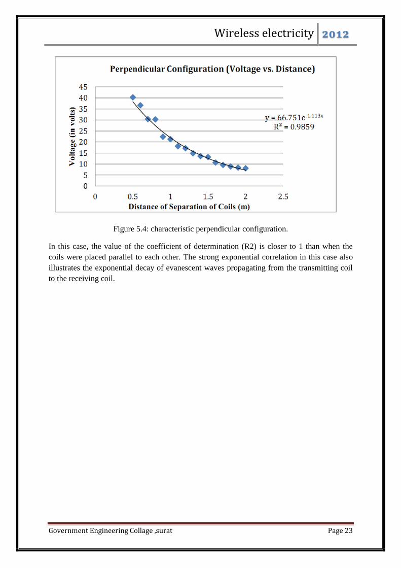
Figure 5.4: characteristic perpendicular configuration.
In this case, the value of the coefficient of determination (R2) is closer to 1 than when the
coils were placed parallel to each other. The strong exponential correlation in this case also
illustrates the exponential decay of evanescent waves propagating from the transmitting coil
to the receiving coil.
Wireless electricity 2012
Government Engineering Collage ,surat Page 24
Chapter : 6 Standby Saver
The Standby Saver application eliminates the need for standby power of devices like
televisions. The idea is to use the energy contained in an RF pulse, sent by the remote control,
to power a switch that turns the device on.
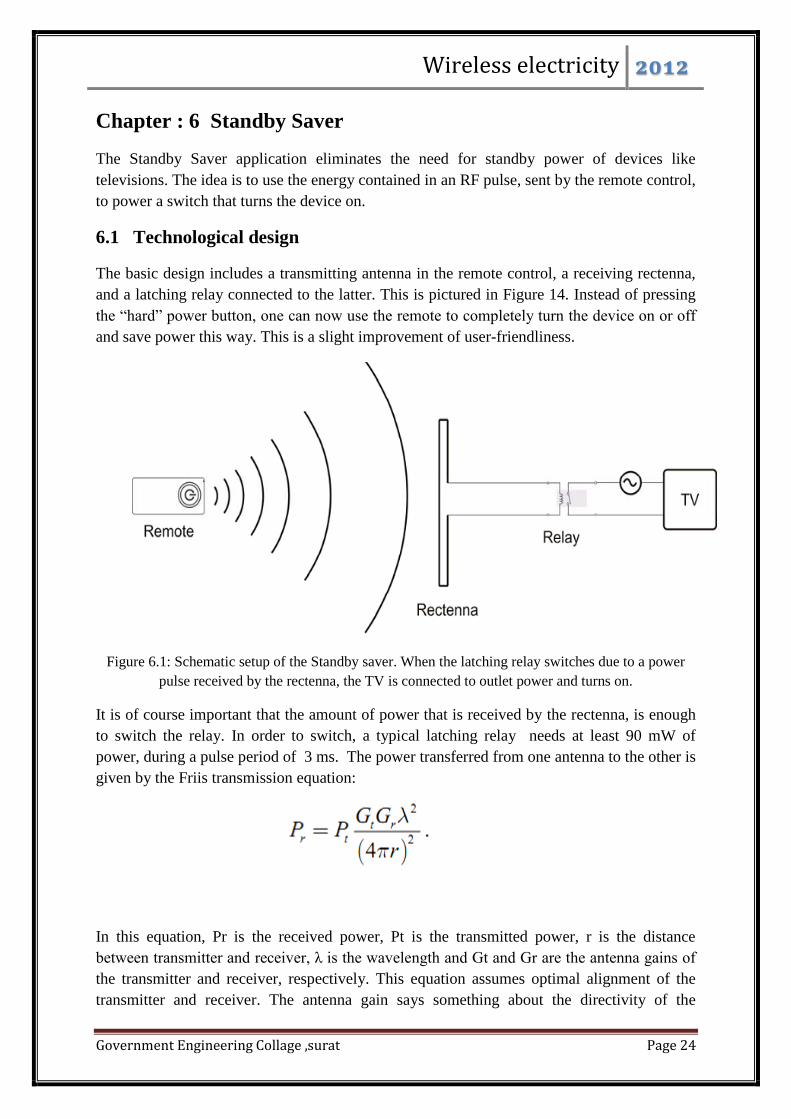
6.1 Technological design
The basic design includes a transmitting antenna in the remote control, a receiving rectenna,
and a latching relay connected to the latter. This is pictured in Figure 14. Instead of pressing
the “hard” power button, one can now use the remote to completely turn the device on or off
and save power this way. This is a slight improvement of user-friendliness.
Figure 6.1: Schematic setup of the Standby saver. When the latching relay switches due to a power
pulse received by the rectenna, the TV is connected to outlet power and turns on.
It is of course important that the amount of power that is received by the rectenna, is enough
to switch the relay. In order to switch, a typical latching relay needs at least 90 mW of
power, during a pulse period of 3 ms. The power transferred from one antenna to the other is
given by the Friis transmission equation:
In this equation, Pr is the received power, Pt is the transmitted power, r is the distance
between transmitter and receiver, λ is the wavelength and Gt and Gr are the antenna gains of
the transmitter and receiver, respectively. This equation assumes optimal alignment of the
transmitter and receiver. The antenna gain says something about the directivity of the

Wireless electricity 2012
Government Engineering Collage ,surat Page 25
antenna. A gain equal to 1 means isotropic radiation in all directions (or reception from all
directions for receiving antennas), a higher gain means the power distribution is more
focused. The antenna gain is given by:
Here, Ae is the effective aperture of the antenna, which is equal to the aperture efficiency
times the physical area of the antenna Ap. The directivity of an antenna a thus increases with
frequency (decreases with wavelength). The aperture efficiency of a typical antenna is
approximately 0.5. Equation (1) can now be written as:
where the extra η factor accounts for the conversion efficiency of the rectenna. Thus, to
optimize power transfer, the antennas should be made as large as possible, and the frequency
as high as possible. However, when the frequency becomes too high, the antenna becomes
too directive, making it harder for the user to point the remote control correctly. A reasonable
size for the antenna in the remote control could be 3cm x 1cm. The one in the television
could be larger, say 10cm x 50cm. A reasonable frequency is 5.8 GHz, which is a license-free
ISM-band. If we assume 5 meter distance between sender and receiver, and incorporate the
limited conversion efficiency of the receiving antenna (η = 83% for printed dipole rectennas,
it can be calculated that the following power is required at the transmitter:
This is a very high power level for a battery-powered device. But this amount of power is
only required for 3 milliseconds. A solution could therefore be to divide the radiated energy
over a larger amount of time. For example, 500 milliseconds at 11.6 watts yields the same
energy as 3 milliseconds at 1934 watts. A capacitive element between rectenna and relay,
could accumulate this energy and discharge with a 3 millisecond pulse. This could however
lead to additional losses. Summarizing, this application could be possible at 5.8 Ghz, with
pulses of 500
milliseconds at about 12 watt input power. However, in practice the power requirement may
be higher because of additional losses which are not accounted for in the above discussion.
Also, the user has to point the remote control correctly for half a second. On the other hand, it
may be possible to optimize relays to have minimal power requirements, which could again
decrease the power needed.

Wireless electricity 2012
Government Engineering Collage ,surat Page 26
6.2 Environmental analysis
The power saved by the Standby Saver will of course be an improvement to the environment.
Currently standby-leakages contribute to 5% of the total domestic power use in developed
countries, thereby using 45 billion kWh of electricity per year in the United States alone.
Leaking electricity will account for 90% of the increase of CO2 emissions from offices and
households between 1990 and 2010. Strong reduction of this type of energy wastage will both
save the environment as well as reduce the operating costs of various domestic electric
devices.
The standby power used, varies widely among different modern TV’s, from a modest 0.31
Watt to an astonishing 76.11 Watt. Average standby power of a TV is estimated at 1.9 Watt.
The average standby energy consumption of TV’s in households is 21.1 kWh/year. This is
not much for a single household, but summed over all households and all other devices, it
does become significant.
However, the Standby Saver will draw more power from batteries than a regular remote
control. By still using infrared signals, or low power RF signals, for the functions to be
performed when the device is on, this extra power is limited. The energy needed for one
on/off switch is 0.5 Joule. The energy contained in two alkaline AA batteries (typical for a
remote control) is 30.8 kJ s 12W=6 × 52. Hence, ideally, one could turn a TV on or off more
than 5 thousand times before replacing batteries. So, because the on/off button is used much
less frequent than the other buttons, the extra battery use is negligible.
One must however keep in mind that the Standby Saver is not suitable for all electronics that
have a standby mode, but only for ones with a remote control. Also, some devices can lose
some functionality when not used in standby mode, like VCRs that use a timer. So relative to
the total standby power consumption, only a small fraction is removed.
Furthermore, implementing this technology in current electronic household devices is
probably not possible since it requires the replacement of current circuitry, which is too
expensive to be beneficial. Hence, only new products can be equipped with this feature.
Summarizing, we have to realize that if this application would become common in new
televisions, only a very slight reduction in domestic power use will probably be noticeable,
over several years of time.
Wireless electricity 2012
Government Engineering Collage ,surat Page 27
6.3 Health hazards
In the past, numerous studies have been carried out on the possible health hazards of RF
radiation. There are a few different ways by which non-iozing electromagnetic radiation can
be hazardous.
The predominant effect of exposure to RF fields is the heating of body tissue as energy is
absorbed by the body. Prolonged exposure to strong RF fields may increase the body
temperature, producing symptoms similar to those of physical activity. In extreme cases, or
when exposed to other sources of heat at the same time, the body's cooling system may be
unable to cope with the heat load.
Thermal effects include heat damage to organs which have poor temperature control, such as
the lens of the eye and the testes, skin burns, deep burns, tissue damage, heat exhaustion, heat
stroke, decreased ability to perform mental or physical tasks and even birth defects.
Besides thermal effects, one of the most important issues to be considered is the possibly
increased risk of cancer by exposure to radiofrequencies. Most epidemiological studies have
found no significant correlation between exposure to radio frequency radiation and an
increased risk of cancer. There is also no replicated evidence of DNA or repair damage due to
RF exposure. Most of RF studies concluded that RF exposure is not genotoxic or mutagenic.
The nature and the degree of the health effects of overexposure to RF fields depend on
frequency, intensity of the fields, duration of exposure and distance from the source.
As mentioned before, the most problematic effect of RF radiation on the body is the heating
effect. A measure that is often used in this context is the Specific Absorption Rate (SAR),
which is the power absorbed by the body per unit mass. At an exposure to electromagnetic
radiation in the frequency range 10 MHz to a few GHz at a SAR value of 4 W/kg for 30
minutes, the body temperature can increase with almost 1 degree Celsius. This result was
found from a study with volunteers.
In terms of tissue properties, the SAR value can be defined as:
In this formula, SAR has units W/kg, σ (S/m) is the electrical conductivity of the absorbing
tissue per meter, ρ (kg/m) is the mass density and Erms is the root-mean-square value of the
electric field, which is equal to ½ 2 Emax, where Emax is the amplitude of the electric
field.
From the intensity of an isotropic radiating source:

Wireless electricity 2012
Government Engineering Collage ,surat Page 28
The amplitude of the electric field can be calculated:
Here, I is the intensity, c is the speed of light, ε0 is the permittivity of free space, εr is the
relative permittivity, Emax the amplitude of the electric field, P the power of the source and
the distance to the source. So the SAR value can also be written as:
For a male human, the average density ρ is approximately 1070 kg/m3. The speed of light
c =3·108 m/s and the permittivity of free space is ε0 = 8.85 · 10−12F/m. The parameters σ
and εr depend strongly on the type of tissue, and the frequency. To determine the SAR value
for the entire human body, an average has to be found for these parameters. In Appendix A,
we have made a calculation of the average σ and εr; the results are σ = 3.87 S/m and εr =
36.9.
Table 6.1: SAR limits for unaware exposure of the general public, according to several
international organizations.
In Table 2, a distinction is made between the limits of average exposure of the entire body,
and the exposure of only a part of the body. For the remote control application, we estimate
that on average, the body is 0.4 m, and the part closest to the transmitter (the thumb) at 0.02
m. Using the input power of 12 Watts proposed in section 5.1, the whole body and partial
body SAR during the transmission of the pulse would become 0.22 W/kg and 88 W/kg,
respectively. However, the SAR limits are defined as an average over 6 minutes (in Europe).

Wireless electricity 2012
Government Engineering Collage ,surat Page 29
Assuming that you will not press the power more than once in six minutes, the SAR values
have to multiplied by (0.5 seconds / 6*60 seconds). This yields 0.00031 and 0.12 W/kg,
respectively, which is well below the allowed values. The SAR will still be in compliance
with regulations if used up to 16 times in the six minutes averaging time.
In the above calculation, the transmitter is assumed to be a perfectly isotropic source. This is
obviously not the case in our application, because the beam is made more directive. If the
user is outside the directive beam, the SAR value will be lower than calculated. Only if the
user is in the course of the directive beam, the SAR will be higher. Based on this, we can
conclude that there are no health hazards caused by this application, because the SAR value is
below allowed safety values. As said before, effects other than body heating have never been
consistently proven, so that is not something to worry about either.
6.4 Economic aspects
Batteries are more expensive than electricity from the power grid. This is mainly because of
the cost of producing batteries and the materials involved. Even though they can be two
thousand times more expensive, consumers still use them in cases where it is impossible or
very inconvenient to use the power grid. This influences both our applications, as in the
bicycle lights we are replacing batteries, while in the power-on function there will be a bigger
drain on the batteries in the remote control.
The standby function on electrical devices, such as TVs, computers and video and DVD
players uses a lot of electric energy. As mentioned before the average standby energy
consumption just for TV’s in households is 21.1 kWh/year. At an energy cost of € 0.20 per
kWh, this means that just € 4.20 is lost. As there are seven million households in the
Netherlands, this is still almost thirty million euros in the Netherlands. An earlier calculation
shows that on normal batteries, the application can be used 5000 times before the batteries
run out. This puts very little extra drain on the batteries. It can be concluded that though the
price of batteries is approximately two thousand times the power grid price, battery use will
not stop customers using this application.
The antenna in the remote control will take up physical space. This will make the remote
bigger and more expensive to make also increasing the price at which consumers buy the TV.
This is even more true for the receiving antenna circuit in the TV. Compared to the total price
of a TV, the extra costs for antennas will not have a large influence.
In conclusion, the TV will become more expensive because of more materials that are used
and using the Standby Saver will save also a little money. But this will not be the deciding
factor in buying one; the environmental aspects will be of more in

Wireless electricity 2012
Government Engineering Collage ,surat Page 30
Chapter 7. : CONCLUSION AND FUTURE WORK:
At the end of the research, we were able to design a system for transmitting watts of power
wirelessly from the transmitting coil to the receiving coil that was enough to light a 40W
bulb. We were able to design discrete components such as the relaxation oscillator, switch
mode-power amplifier and a full bridge voltage rectifier for the system design process. We
also managed to demonstrate evanescent waves by measuring exponential decay of voltage as
an increase in distance between the transmitter and the receiver coils.
There can be significant research work that can be done in the future of this research. Future
work includes connecting the relaxation oscillator with the power amplifier using current
amplifier chip for providing enough current to drive the gate of the MOSFET to drive the
efficient class D H-Bridge power amplifier. Also, reduction in the size of the transmitting and
receiving coils and utilizing the regulated signal to power a DC load could be something that
could be worked in the future as a means to make this system feasible for practical
applications.

Wireless electricity 2012
Government Engineering Collage ,surat Page 31
CHAPTER 8: REFERENCES:
8.1 ORIGINAL MIT PAPER:
[1]Andre Kurs, Aristeidis Karalis, Robert Moffatt, J. D. Joannopoulos, Peter Fisher, Marin
Soljacic. 2008. Wireless Power Transfer via Strongly Coupled Magnetic Resonances.Science.
http://www.sciencemag.org/cgi/rapidpdf/1143254?ijkey=94ff.Ay4jRMqU&keytype=ref&site
id=sci (accessed December 5, 2011).
8.2 LINK TO THE PROJECT BY ADAM AND LUCAS:
[2]http://www.cornellcollege.edu/physics/courses/phy312/Student-Projects/Magnetic-
Resonance/Magnetic-Resonance.html
8.3 THEORY AND COMPONENTS DESIGN:
[3] G. L. Peterson, “THE WIRELESS TRANSMISSION OF ELECTRICAL ENERGY,”
[online document], 2004, [cited 12/10/04], http://www.tfcbooks.com/articles/tws8c.htm
[4] U.S. Department of Energy, “Energy Savers: Solar Power Satellites,” [online document]
rev 2004 June 17, [cited 12/10/04],
http://www.eere.energy.gov/consumerinfo/factsheets/l123.html
[5] S. Kopparthi, Pratul K. Ajmera, "Power delivery for remotely located Microsystems,"
Proc. Of IEEE Region 5, 2004 Annual Tech. Conference, 2004 April 2, pp. 31-39.
[6] Tomohiro Yamada, Hirotaka Sugawara, Kenichi Okada, Kazuya Masu, Akio Oki and
Yasuhiro Horiike,"Battery-less Wireless Communication System through Human Body for
in-vivo Healthcare Chip,"IEEE Topical Meeting on Silicon Monolithic Integrated Circuits in
RF Systems, pp. 322-325, Sept. 2004.
[7] “Category: Radio spectrum -Wikipedia, the free encyclopedia,” [online document], 2004
Aug 26 [cited 12/11/04], http://en.wikipedia.org/wiki/Category:Radio_spectrum.
[8] Zia A. Yamayee and Juan L. Bala, Jr., Electromechanical Energy Devices and Power
Systems, John Wiley and Sons, 1947
[9] “The Spark Transmitter. 2. Maximizing Power, part 1. “ November
2004,http://home.freeuk.net/dunckx/wireless/maxpower1/maxpower1.html.
[10] R. Victor Jones, “Diode Applications,” [Online Document], 2001 Oct 25, [cited 2004
Dec 11],
http://people.deas.harvard.edu/~jones/es154/lectures/lecture_2/diode_circuits/diode_appl.htm
l.

Wireless electricity 2012
Government Engineering Collage ,surat Page 32
[11] Central Semiconductor Corp, “PNP Silicon Transistor”, November
2004,http://www.semiconductors.philips.com/acrobat_download/datasheets/2N2222_CNV_2
.pdf.
[12] Neha Bagga, Joshua Gruntmeir, Samuel Lewis, “Wireless Power Transmission”,
Dec.2004.