Embed Size (px)
Citation preview
INSTRUCTION MANUAL
AP-90MWIRELESS ACCESS POINT
[IEEE802.11ac] standard[IEEE802.11n] standard
[IEEE802.11a/b/g] standardDual band communications[IEEE802.3af] PoE standard
INTRODUCTION
1 BEFORE USING THE AP-90M
2 INSTALLATION GUIDE
3 CONNECTING WIRELESS LAN [BASIC]
4 CONNECTING WIRELESS LAN [ADVANCED]
5 OTHER FUNCTIONS
6 MAINTENANCE
7 INFORMATION

i
INTRODUCTION
Form2001
Thank you for choosing this Icom product. The AP-90M wireless access point is designed and built with Icom’s IP network technology. We hope you agree with Icom’s philosophy of “technology first.” Many hours of research and development went into the design of your AP-90M.The AP-90M complies with the IEEE802.11ac/n/a/b/g standards and enables you to communicate in dual bands.
➥ The wireless LAN unit for the internal and external antenna is built into the AP-90M. The IEEE802.11ac standard can only be used when 5 GHz is selected for the external antenna.
➥ If you set the same frequency band to the internal antenna and the external antenna, the wireless system will not work properly.
ALL RIGHTS RESERVED. This document contains material protected under International and Domestic Copyright Laws and Treaties. Any unauthorized reprint or use of this material is prohibited. No part of this document may be reproduced or transmitted in any form or by any means, electronic or mechanical, including photocopying, recording, or by any information storage and retrieval system without express written permission from Icom Incorporated.All stated specifications and design are subject to change without notice or obligation.
Adobe and Reader are registered trademarks of Adobe Systems Incorporated in the United States and/or other countries.Microsoft and Windows are registered trademarks of Microsoft Corporation in the United States and/or other countries.Icom, Icom Inc. and the Icom logo are registered trademarks of Icom Incorporated (Japan) in Japan, the United States, the United Kingdom, Germany, France, Spain, Russia, Australia, New Zealand, and/or other countries.All other products or brands are registered trademarks or trademarks of their respective holders.
INTRODUCTION
Form2001
ii
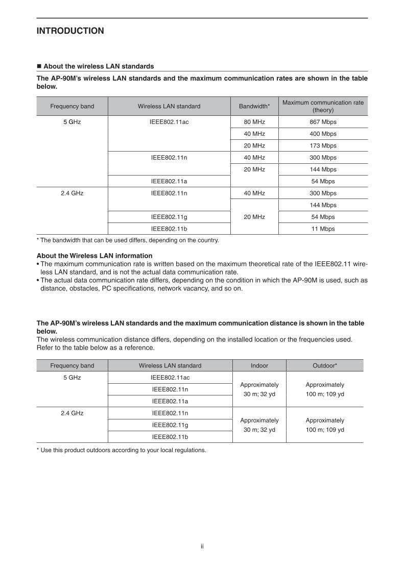
About the wireless LAN standards
The AP-90M’s wireless LAN standards and the maximum communication rates are shown in the table below.
Frequency band Wireless LAN standard Bandwidth*Maximum communication rate
(theory)
5 GHz IEEE802.11ac 80 MHz 867 Mbps
40 MHz 400 Mbps
20 MHz 173 Mbps
IEEE802.11n 40 MHz 300 Mbps
20 MHz 144 Mbps
IEEE802.11a 54 Mbps
2.4 GHz IEEE802.11n 40 MHz 300 Mbps
20 MHz
144 Mbps
IEEE802.11g 54 Mbps
IEEE802.11b 11 Mbps
Frequency band Wireless LAN standard Indoor Outdoor*
5 GHz IEEE802.11acApproximately
30 m; 32 yd
Approximately
100 m; 109 ydIEEE802.11n
IEEE802.11a
2.4 GHz IEEE802.11nApproximately
30 m; 32 yd
Approximately
100 m; 109 ydIEEE802.11g
IEEE802.11b
About the Wireless LAN information• The maximum communication rate is written based on the maximum theoretical rate of the IEEE802.11 wire-
less LAN standard, and is not the actual data communication rate.• The actual data communication rate differs, depending on the condition in which the AP-90M is used, such as
distance, obstacles, PC specifications, network vacancy, and so on.
The AP-90M’s wireless LAN standards and the maximum communication distance is shown in the table below.The wireless communication distance differs, depending on the installed location or the frequencies used.Refer to the table below as a reference.
* The bandwidth that can be used differs, depending on the country.
* Use this product outdoors according to your local regulations.
INTRODUCTION
Form2001
iii
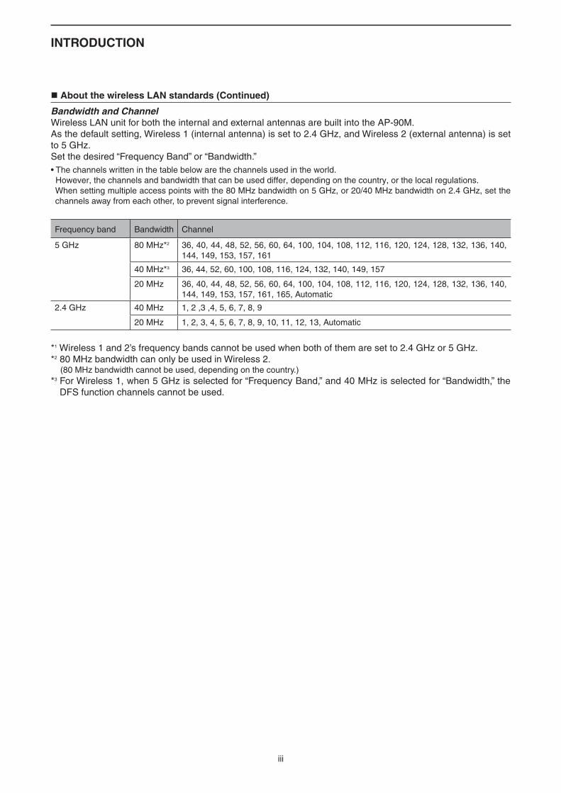
About the wireless LAN standards (Continued)
Bandwidth and ChannelWireless LAN unit for both the internal and external antennas are built into the AP-90M.As the default setting, Wireless 1 (internal antenna) is set to 2.4 GHz, and Wireless 2 (external antenna) is set to 5 GHz.Set the desired “Frequency Band” or “Bandwidth.”• The channels written in the table below are the channels used in the world. However, the channels and bandwidth that can be used differ, depending on the country, or the local regulations. When setting multiple access points with the 80 MHz bandwidth on 5 GHz, or 20/40 MHz bandwidth on 2.4 GHz, set the channels away from each other, to prevent signal interference.
Frequency band Bandwidth Channel
5 GHz 80 MHz*2 36, 40, 44, 48, 52, 56, 60, 64, 100, 104, 108, 112, 116, 120, 124, 128, 132, 136, 140, 144, 149, 153, 157, 161
40 MHz*3 36, 44, 52, 60, 100, 108, 116, 124, 132, 140, 149, 157
20 MHz 36, 40, 44, 48, 52, 56, 60, 64, 100, 104, 108, 112, 116, 120, 124, 128, 132, 136, 140, 144, 149, 153, 157, 161, 165, Automatic
2.4 GHz 40 MHz 1, 2 ,3 ,4, 5, 6, 7, 8, 9
20 MHz 1, 2, 3, 4, 5, 6, 7, 8, 9, 10, 11, 12, 13, Automatic
*1 Wireless 1 and 2’s frequency bands cannot be used when both of them are set to 2.4 GHz or 5 GHz.*2 80 MHz bandwidth can only be used in Wireless 2. (80 MHz bandwidth cannot be used, depending on the country.)*3 For Wireless 1, when 5 GHz is selected for “Frequency Band,” and 40 MHz is selected for “Bandwidth,” the
DFS function channels cannot be used.
INTRODUCTION
Form2001
iv
Features
➥ A communication can be made on the maximum rate 867 Mbps (theory) based on the [IEEE802.11ac] and the [IEEE802.11n] standards.
• The [IEEE802.11ac] standard can only be used when 5 GHz is selected for the external antenna. • The [IEEE802.11ac] and the [IEEE802.11n] standards are enabled when “None” or “AES” are set for “Encryption.”
➥ Dual band communications using the 5 GHz and 2.4 GHz bands can be made, based on the [IEEE802.11a] and the [IEEE802.11b/g] standards.
➥ For using multiple wireless devices that are based on different wireless LAN standards at the same time, a protection system is built into the AP-90M, for the communication rate maintenance.
➥ The DFS function automatically avoids radio-frequency interference to Weather radars. The DFS conditions differ, depending on your location.
➥ The authentication system supports “Open System,” “Shared Key,” “IEEE802.1X,” “WPA,” “WPA2,” “WPA-PSK,” and “WPA2-PSK.”
➥ If “IEEE802.1X,” “WPA” or “WPA2” is selected, the RADIUS authentication server can be used.
➥ Web authentication function, which authorizes wireless LAN stations is built into the AP-90M.
➥ The AP-90M complies with the PoE (Power over Ethernet) power reception function based on the [IEEE802.3af] standard. Therefore, power can be received using a HUB (user supplied) that supports the [IEE802.3af] stan-dard.
➥ With the function that the “Wi-Fi Alliance” proposes, SSID and Security (WPA-PSK/WPA2-PSK) can automati-cally be set to the AP-90M (virtual AP) and the wireless LAN station that supports the WPS (Wi-Fi Protected Setup) function.
• This device is not certified by the Wi-Fi alliance. (As of July 2017)
➥ Supports the 10BASE-T/100BASE-TX/1000BASE-T automatic switching function.
➥ Auto MDI/MDI-X system for the port polarity.
➥ Settings can be automatically backed-up at power ON, using a USB flash drive. Also, the firmware can be updated or settings can be restored, using a flash drive. • To use these functions, a setting file or a firmware file with a proper file name is required.
➥ Set the “USB Authentication Key” function to avoid data theft or accidental setting changes, using other than the USB flash drive set to this function.
➥ Supports the SNMP system for the network management.
➥ No license nor certificate needed to use this product.
v
INTRODUCTION
Form2001
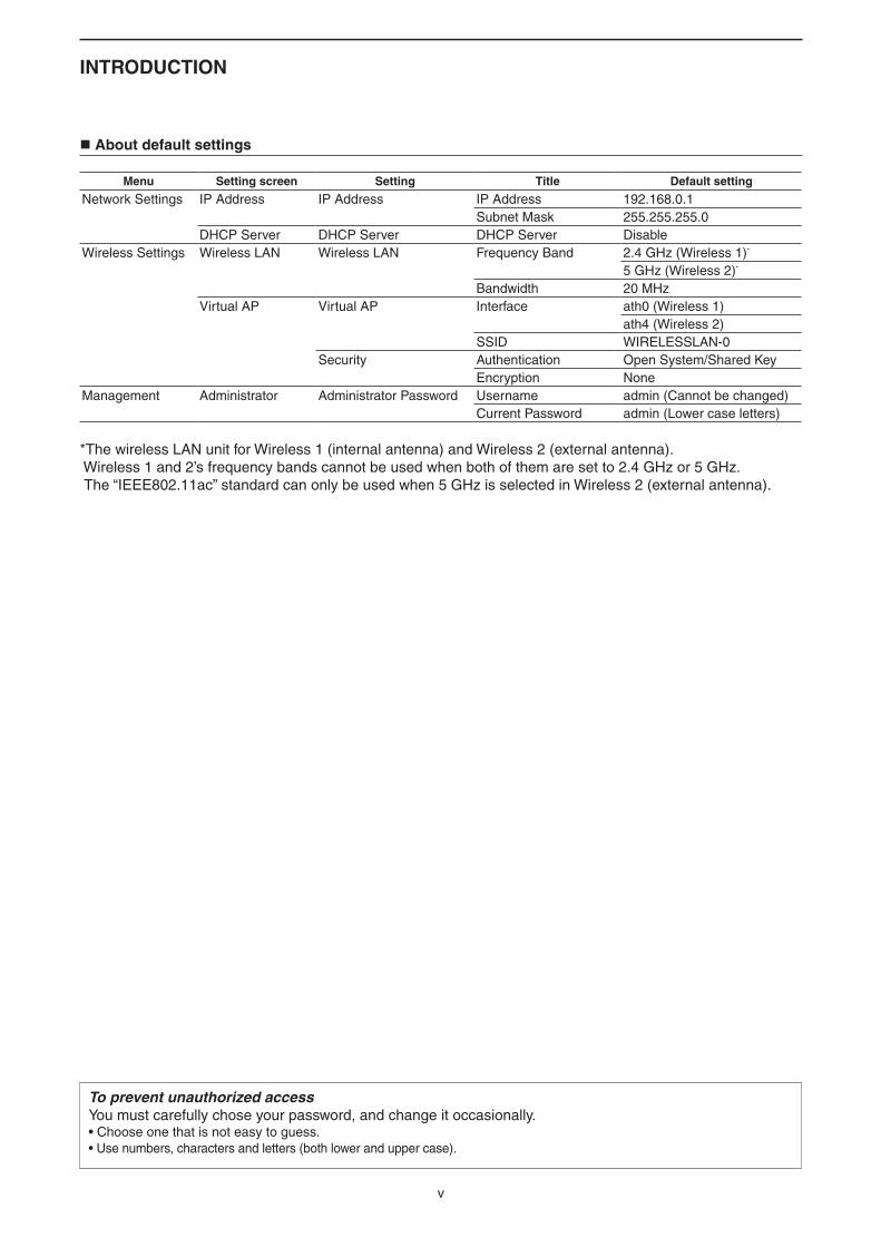
Menu Setting screen Setting Title Default setting
Network Settings IP Address IP Address IP Address 192.168.0.1Subnet Mask 255.255.255.0
DHCP Server DHCP Server DHCP Server DisableWireless Settings Wireless LAN Wireless LAN Frequency Band 2.4 GHz (Wireless 1)*
5 GHz (Wireless 2)*
Bandwidth 20 MHzVirtual AP Virtual AP Interface ath0 (Wireless 1)
ath4 (Wireless 2)SSID WIRELESSLAN-0
Security Authentication Open System/Shared KeyEncryption None
Management Administrator Administrator Password Username admin (Cannot be changed)Current Password admin (Lower case letters)
*The wireless LAN unit for Wireless 1 (internal antenna) and Wireless 2 (external antenna). Wireless 1 and 2’s frequency bands cannot be used when both of them are set to 2.4 GHz or 5 GHz. The “IEEE802.11ac” standard can only be used when 5 GHz is selected in Wireless 2 (external antenna).
To prevent unauthorized accessYou must carefully chose your password, and change it occasionally.• Choose one that is not easy to guess.• Use numbers, characters and letters (both lower and upper case).
About default settings
vi
INTRODUCTION
Form2001
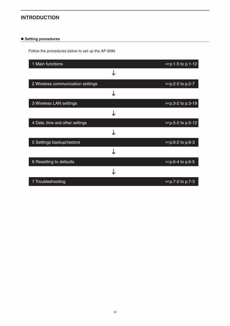
Setting procedures
Follow the procedures below to set up the AP-90M.
1 Main functions +p.1-5 to p.1-12
2 Wireless communication settings +p.2-2 to p.2-7
3 Wireless LAN settings +p.3-2 to p.3-19
4 Date, time and other settings +p.5-2 to p.5-12
5 Settings backup/restore +p.6-2 to p.6-3
6 Resetting to defaults +p.6-4 to p.6-5
7 Troubleshooting +p.7-2 to p.7-3
INTRODUCTION
Form2001
vii
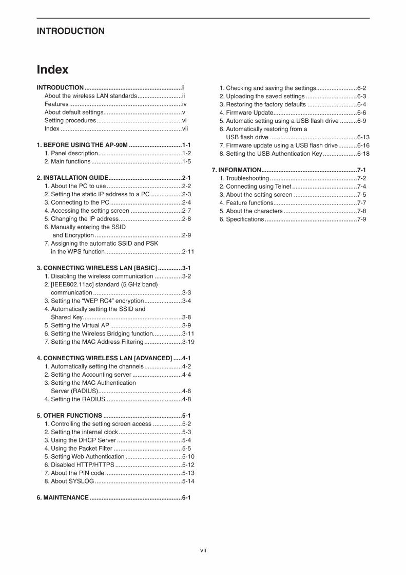
IndexINTRODUCTION .........................................................i About the wireless LAN standards ..........................ii Features ..................................................................iv About default settings..............................................v Setting procedures ..................................................vi Index .......................................................................vii
1. BEFORE USING THE AP-90M ...............................1-1 1. Panel description .................................................1-2 2. Main functions .....................................................1-5
2. INSTALLATION GUIDE ...........................................2-1 1. About the PC to use ............................................2-2 2. Setting the static IP address to a PC ..................2-3 3. Connecting to the PC ..........................................2-4 4. Accessing the setting screen ..............................2-7 5. Changing the IP address .....................................2-8 6. Manually entering the SSID
and Encryption ...................................................2-9 7. Assigning the automatic SSID and PSK
in the WPS function .............................................2-11
3. CONNECTING WIRELESS LAN [BASIC] ..............3-1 1. Disabling the wireless communication ................3-2 2. [IEEE802.11ac] standard (5 GHz band)
communication ....................................................3-3 3. Setting the “WEP RC4” encryption ......................3-4 4. Automatically setting the SSID and
Shared Key ..........................................................3-8 5. Setting the Virtual AP ..........................................3-9 6. Setting the Wireless Bridging function.................3-11 7. Setting the MAC Address Filtering ......................3-19
4. CONNECTING WIRELESS LAN [ADVANCED] .....4-1 1. Automatically setting the channels ......................4-2 2. Setting the Accounting server .............................4-4 3. Setting the MAC Authentication
Server (RADIUS) .................................................4-6 4. Setting the RADIUS ............................................4-8
5. OTHER FUNCTIONS ..............................................5-1 1. Controlling the setting screen access .................5-2 2. Setting the internal clock .....................................5-3 3. Using the DHCP Server ......................................5-4 4. Using the Packet Filter ........................................5-5 5. Setting Web Authentication .................................5-10 6. Disabled HTTP/HTTPS .......................................5-12 7. About the PIN code .............................................5-13 8. About SYSLOG ...................................................5-14
6. MAINTENANCE ......................................................6-1
1. Checking and saving the settings ........................6-2 2. Uploading the saved settings ..............................6-3 3. Restoring the factory defaults .............................6-4 4. Firmware Update .................................................6-6 5. Automatic setting using a USB flash drive ..........6-9 6. Automatically restoring from a
USB flash drive ...................................................6-13 7. Firmware update using a USB flash drive ...........6-16 8. Setting the USB Authentication Key ....................6-18
7. INFORMATION ........................................................7-1 1. Troubleshooting ...................................................7-2 2. Connecting using Telnet ......................................7-4 3. About the setting screen .....................................7-5 4. Feature functions .................................................7-7 5. About the characters ...........................................7-8 6. Specifications ......................................................7-9

1-1
BEFORE USING THE AP-90M 1
1. Panel description .....................................................................................................................................1-2 Top panel ...............................................................................................................................................1-2 Rear panel/Back side .............................................................................................................................1-3 Antenna attachment ...............................................................................................................................1-42. Main functions .........................................................................................................................................1-5 Access point function .............................................................................................................................1-5 Wireless LAN (SSID) .............................................................................................................................1-5 Maximum Number of Stations ...............................................................................................................1-5 ‘IEEE802.11ac’ standard ........................................................................................................................1-5 ‘IEEE802.11n’ standard .........................................................................................................................1-5 Wireless LAN (SSID) .............................................................................................................................1-6 Roaming function ...................................................................................................................................1-7 Wireless bridging function ......................................................................................................................1-8 Wireless bridging function (Continued) ..................................................................................................1-9 Virtual AP function .................................................................................................................................1-10 DFS function and automatic channel setting .........................................................................................1-11 WPS function .........................................................................................................................................1-12
1 BEFORE USING THE AP-90M
1-2
1. Panel description
Top panel
q w e r
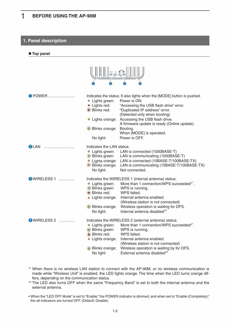
q POWER ………………… Indicates the status. It also lights when the [MODE] button is pushed. Lights green: Power is ON. Lights red: “Accessing the USB flash drive” error. Blinks red: “Duplicated IP address” error.
(Detected only when booting) Lights orange: Accessing the USB flash drive.
A firmware update is ready (Online update). Blinks orange: Booting.
When [MODE] is operated. No light: Power is OFF.
w LAN …………………… Indicates the LAN status. Lights green: LAN is connected (1000BASE-T)
Blinks green: LAN is communicating (1000BASE-T) Lights orange: LAN is connected (10BASE-T/100BASE-TX)
Blinks orange: LAN is communicating (10BASE-T/100BASE-TX) No light: Not connected.
e WIRELESS 1 ………… Indicates the WIRELESS 1 (internal antenna) status. Lights green: More than 1 connection/WPS succeeded*1.
Blinks green: WPS is running. Blinks red: WPS failed. Lights orange: Internal antenna enabled. (Wireless station is not connected) Blinks orange: Wireless operation is waiting for DFS.
No light: Internal antenna disabled*2
r WIRELESS 2 ………… Indicates the WIRELESS 2 (external antenna) status. Lights green: More than 1 connection/WPS succeeded*1.
Blinks green: WPS is running. Blinks red: WPS failed. Lights orange: Internal antenna enabled. (Wireless station is not connected) Blinks orange: Wireless operation is waiting by for DFS.
No light: External antenna disabled*2
*1 When there is no wireless LAN station to connect with the AP-90M, or no wireless communication is made while “Wireless Unit” is enabled, the LED lights orange. The time when the LED turns orange dif-fers, depending on the communication status.
*2 The LED also turns OFF when the same “Frequency Band” is set to both the internal antenna and the external antenna.
• When the “LED OFF Mode” is set to “Enable,” the POWER indicator is dimmed, and when set to “Enable (Completely),” the all indicators are turned OFF. (Default: Disable)
1 BEFORE USING THE AP-90M
1-3
1. Panel description (Continued)
DC GNDLANUSBWPSq
w
e
r
t
y
u
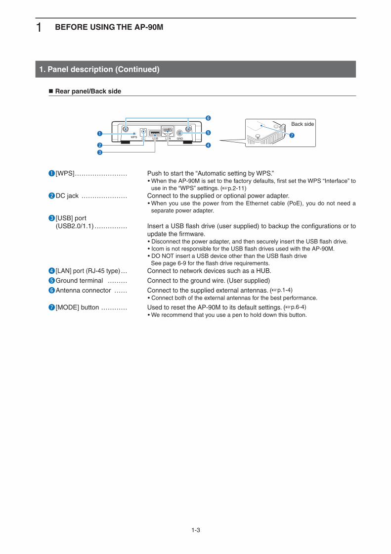
Back side
q [WPS] …………………… Push to start the “Automatic setting by WPS.”• When the AP-90M is set to the factory defaults, first set the WPS “Interface” to
use in the “WPS” settings. (+p.2-11)w DC jack ………………… Connect to the supplied or optional power adapter.
• When you use the power from the Ethernet cable (PoE), you do not need a separate power adapter.
e [USB] port (USB2.0/1.1) …………… Insert a USB flash drive (user supplied) to backup the configurations or to
update the firmware.• Disconnect the power adapter, and then securely insert the USB flash drive.• Icom is not responsible for the USB flash drives used with the AP-90M.• DO NOT insert a USB device other than the USB flash drive See page 6-9 for the flash drive requirements.
r [LAN] port (RJ-45 type) … Connect to network devices such as a HUB.
t Ground terminal ……… Connect to the ground wire. (User supplied)
y Antenna connector …… Connect to the supplied external antennas. (+p.1-4)• Connect both of the external antennas for the best performance.
u [MODE] button ………… Used to reset the AP-90M to its default settings. (+p.6-4)• We recommend that you use a pen to hold down this button.
Rear panel/Back side
1 BEFORE USING THE AP-90M
1-4
1. Panel description (Continued)
AP-90M
WIRELESS ACCESS POINT
Antenna x2(Supplied)
Rotate to the right
0˚
AP-90M
45˚
90˚
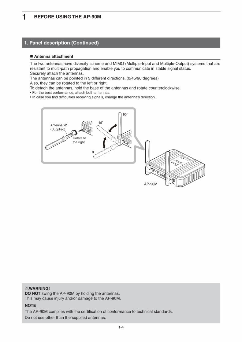
RWARNING!DO NOT swing the AP-90M by holding the antennas. This may cause injury and/or damage to the AP-90M.
NOTEThe AP-90M complies with the certification of conformance to technical standards.
Do not use other than the supplied antennas.
Antenna attachment
The two antennas have diversity scheme and MIMO (Multiple-Input and Multiple-Output) systems that are resistant to multi-path propagation and enable you to communicate in stable signal status.Securely attach the antennas.The antennas can be pointed in 3 different directions. (0/45/90 degrees)Also, they can be rotated to the left or right.To detach the antennas, hold the base of the antennas and rotate counterclockwise.• For the best performance, attach both antennas.• In case you find difficulties receiving signals, change the antenna’s direction.

1 BEFORE USING THE AP-90M
1-5
2. Main functions
Access point function
The AP-90M is a wireless access point that complies with the “IEEE802.11ac” and “IEEE802.11n” stan-dards. It is designed for dual band communications in the 2.4 GHz and 5 GHz bands.• Communication with wireless LAN stations that comply with “IEEE802.11 (14CH)” cannot be made.
Wireless LAN (SSID)
An SSID (or ESS ID) is preset in the AP-90M and the wireless LAN to separate the connecting destination. (+p.2-9)• The AP-90M is equipped with a wireless LAN unit using internal and external antenna. To use multiple virtual APs, the same SSIDs cannot be set in one unit.
Maximum Number of Stations
This function limits the number of wireless LAN stations that can be connected at a time to each virtual AP. This prevents the communication traffic speed from being reducing.
‘IEEE802.11ac’ standard
With data communication using a quadruple frequency bandwidth (channel) and multiple antennas, com-munication with a maximum speed of 867 Mbps* (theoretical value) can be made.* The ‘IEEE802.11ac’ standard can be used only when Encryption is set to “None” or “AES.” The maximum speed of 867 Mbps (theoretical value) can only be used on the external antenna (Wireless 2) and when the Frequency Band is set to “5 GHz.”
In addition, the Bandwidth must be set to “80 MHz” to use the maximum 867 Mbps. (+p.3-3) • The ‘IEEE802.11ac’ is compatible with the ‘IEEE802.11n/a’ standard.
‘IEEE802.11n’ standard
With data communication using a double frequency bandwidth (channel) and multiple antennas, communi-cation with a maximum speed of 300 Mbps* (theoretical value) can be made.* The ‘IEEE802.11n’ standard can be used only when Encryption is set to “None” or “AES.” In addition, the Bandwidth must be set to “40 MHz” to use the maximum of 300 Mbps. (+p.3-3) • The ‘IEEE802.11n’ is compatible with the ‘IEEE802.11a/b/g’ standard.
192.168.0.10192.168.0.1192.168.0.11
PC PCAP-90M
5 GHz band 2.4 GHz band
1 BEFORE USING THE AP-90M
1-6
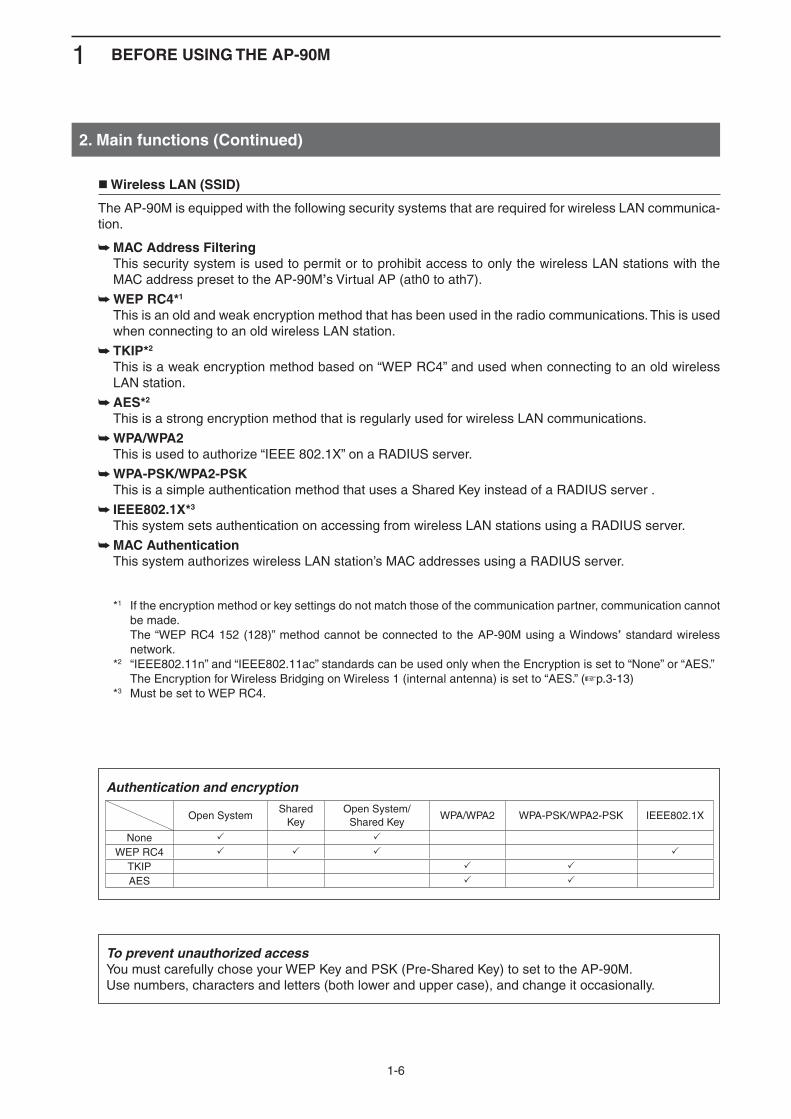
Open SystemShared
KeyOpen System/
Shared KeyWPA/WPA2 WPA-PSK/WPA2-PSK IEEE802.1X
None
WEP RC4
TKIP
AES
Wireless LAN (SSID)
The AP-90M is equipped with the following security systems that are required for wireless LAN communica-tion.
MAC Address Filtering ➥ This security system is used to permit or to prohibit access to only the wireless LAN stations with the
MAC address preset to the AP-90M’s Virtual AP (ath0 to ath7).
WEP RC4* ➥ 1
This is an old and weak encryption method that has been used in the radio communications. This is used when connecting to an old wireless LAN station.
TKIP* ➥ 2
This is a weak encryption method based on “WEP RC4” and used when connecting to an old wireless LAN station.
AES* ➥ 2
This is a strong encryption method that is regularly used for wireless LAN communications.
WPA/WPA2 ➥ This is used to authorize “IEEE 802.1X” on a RADIUS server.
WPA-PSK/WPA2-PSK ➥ This is a simple authentication method that uses a Shared Key instead of a RADIUS server .
IEEE802.1X* ➥ 3
This system sets authentication on accessing from wireless LAN stations using a RADIUS server.
MAC Authentication ➥ This system authorizes wireless LAN station’s MAC addresses using a RADIUS server.
*1 If the encryption method or key settings do not match those of the communication partner, communication cannot be made.
The “WEP RC4 152 (128)” method cannot be connected to the AP-90M using a Windows’ standard wireless network.
*2 “IEEE802.11n” and “IEEE802.11ac” standards can be used only when the Encryption is set to “None” or “AES.” The Encryption for Wireless Bridging on Wireless 1 (internal antenna) is set to “AES.” (+p.3-13) *3 Must be set to WEP RC4.
2. Main functions (Continued)
Authentication and encryption
To prevent unauthorized accessYou must carefully chose your WEP Key and PSK (Pre-Shared Key) to set to the AP-90M.Use numbers, characters and letters (both lower and upper case), and change it occasionally.
1 BEFORE USING THE AP-90M
1-7
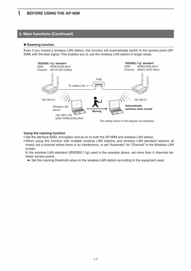
Roaming function
Even if you moved a wireless LAN station, this function will automatically switch to the access point (AP-90M) with the best signal. This enables you to use the wireless LAN station in larger areas.
Using the roaming function• Set the identical SSID, encryption and so on to both the AP-90M and wireless LAN station.• When using this function with multiple wireless LAN stations and wireless LAN standard stations all
mixed, set a channel where there is no interference, or set “Automatic” for “Channel” in the Wireless LAN screen.
In the wireless LAN standard (IEEE802.11g) used in the example above, set more than 4 channels be-tween access points.
Set the roaming threshold value on the wireless LAN station according to the equipment used. ➥
2. Main functions (Continued)
To cabled LAN
HUB
192.168.0.100SSID: WIRELESSLAN-0
192.168.0.2 192.168.0.1
“IEEE802.11g” standardSSID: WIRELESSLAN-0Channel: 001CH (2412 MHz)
Wireless LANdevice Moving
Automatically switches when moved
“IEEE802.11g” standardSSID: WIRELESSLAN-0Channel: 006CH (2437 MHz)
The setting values in this diagram are examples.
1 BEFORE USING THE AP-90M
1-8
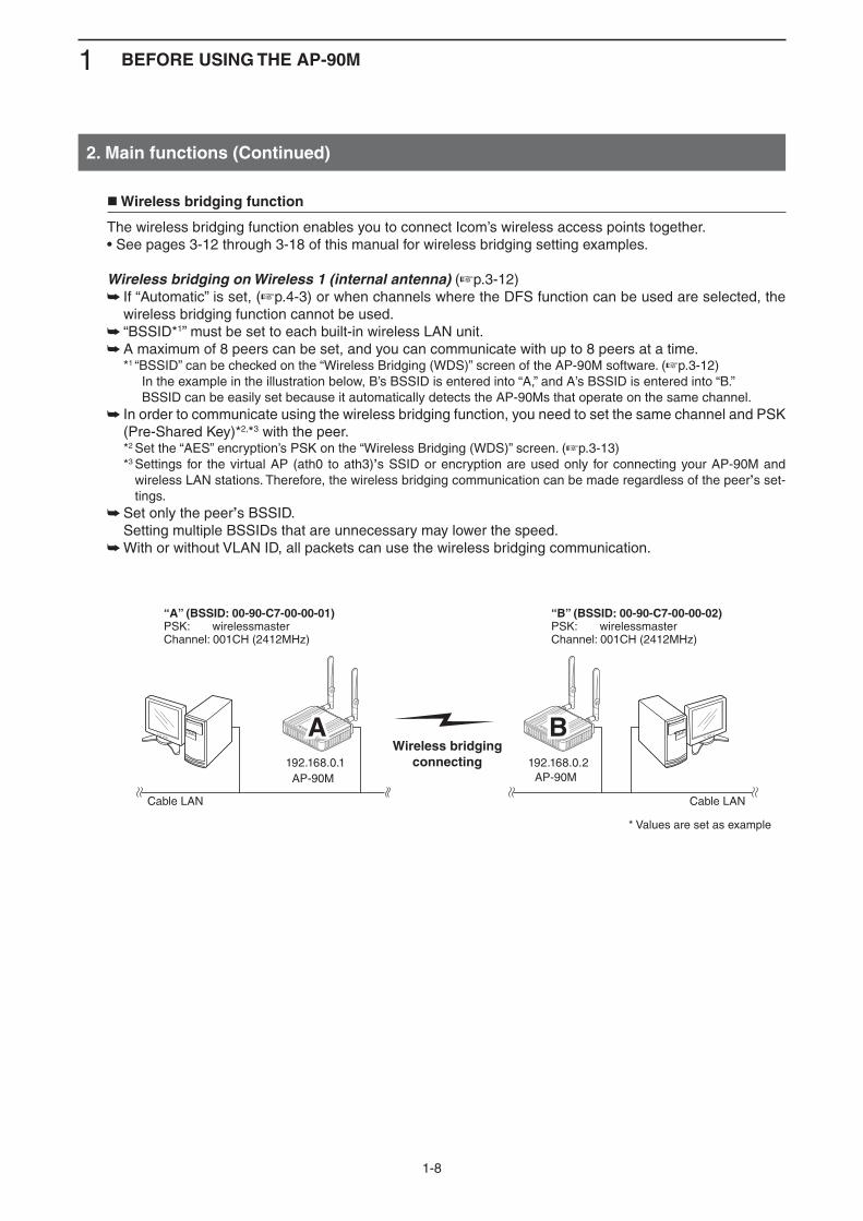
Wireless bridging function
The wireless bridging function enables you to connect Icom’s wireless access points together.• See pages 3-12 through 3-18 of this manual for wireless bridging setting examples.
Wireless bridging on Wireless 1 (internal antenna) (+p.3-12) If “Automatic” is set, ( ➥ +p.4-3) or when channels where the DFS function can be used are selected, the wireless bridging function cannot be used.“BSSID* ➥ 1” must be set to each built-in wireless LAN unit.A maximum of 8 peers can be set, and you can communicate with up to 8 peers at a time. ➥
*1 “BSSID” can be checked on the “Wireless Bridging (WDS)” screen of the AP-90M software. (+p.3-12) In the example in the illustration below, B’s BSSID is entered into “A,” and A’s BSSID is entered into “B.” BSSID can be easily set because it automatically detects the AP-90Ms that operate on the same channel.
In order to communicate using the wireless bridging function, you need to set the same channel and PSK ➥(Pre-Shared Key)*2,*3 with the peer.
*2 Set the “AES” encryption’s PSK on the “Wireless Bridging (WDS)” screen. (+p.3-13) *3 Settings for the virtual AP (ath0 to ath3)’s SSID or encryption are used only for connecting your AP-90M and
wireless LAN stations. Therefore, the wireless bridging communication can be made regardless of the peer’s set-tings.
Set only the peer ➥ ’s BSSID. Setting multiple BSSIDs that are unnecessary may lower the speed.
With or without VLAN ID, all packets can use the wireless bridging communication. ➥
2. Main functions (Continued)
* Values are set as example
Wireless bridgingconnecting
AA BB
Cable LAN Cable LAN
“A” (BSSID: 00-90-C7-00-00-01)PSK: wirelessmasterChannel: 001CH (2412MHz)
192.168.0.1 192.168.0.2
“B” (BSSID: 00-90-C7-00-00-02)PSK: wirelessmasterChannel: 001CH (2412MHz)
AP-90M AP-90M
1 BEFORE USING THE AP-90M
1-9
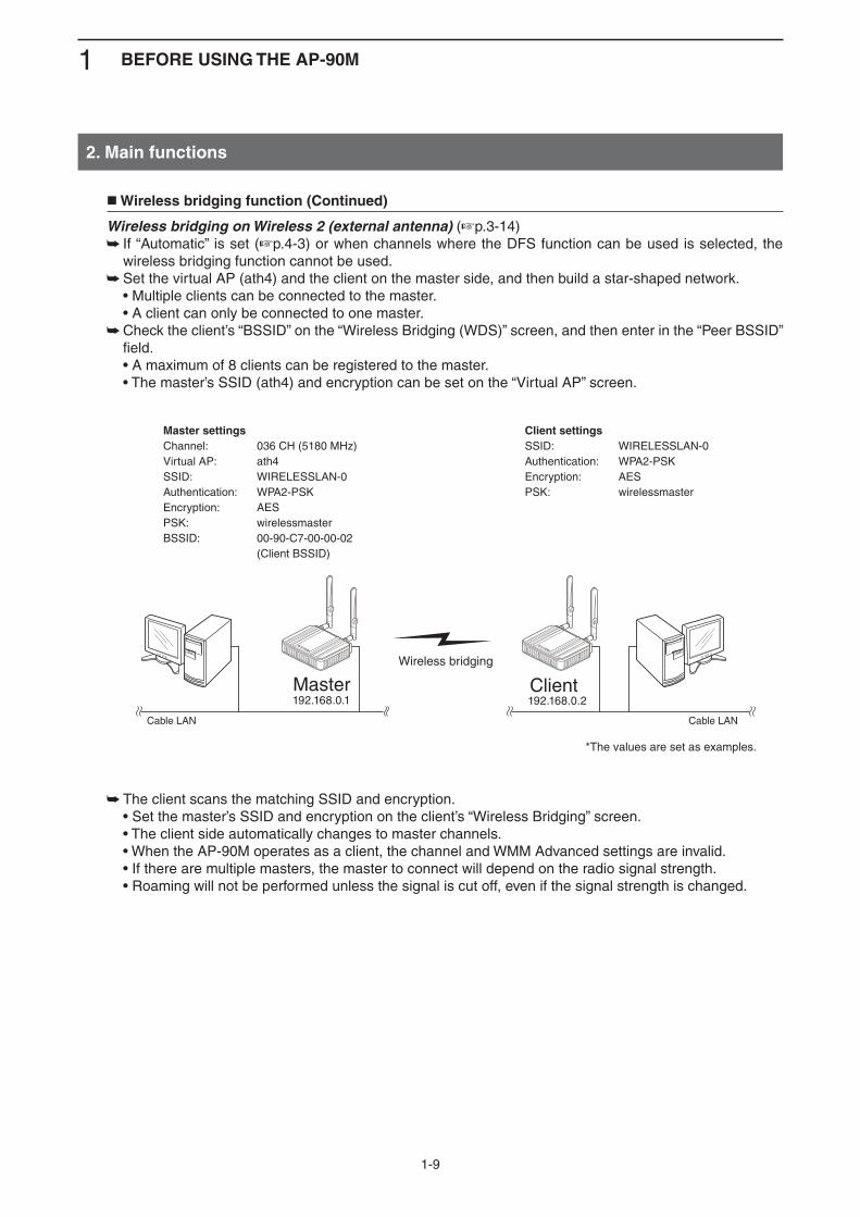
Wireless bridging function (Continued)
Wireless bridging on Wireless 2 (external antenna) (+p.3-14) If “Automatic” is set ( ➥ +p.4-3) or when channels where the DFS function can be used is selected, the wireless bridging function cannot be used.Set the virtual AP (ath4) and the client on the master side, and then build a star-shaped network. ➥
• Multiple clients can be connected to the master. • A client can only be connected to one master.
Check the client’s “BSSID” on the “Wireless Bridging (WDS)” screen, and then enter in the “Peer BSSID” ➥field.
• A maximum of 8 clients can be registered to the master. • The master’s SSID (ath4) and encryption can be set on the “Virtual AP” screen.
The client scans the matching SSID and encryption. ➥ • Set the master’s SSID and encryption on the client’s “Wireless Bridging” screen. • The client side automatically changes to master channels. • When the AP-90M operates as a client, the channel and WMM Advanced settings are invalid. • If there are multiple masters, the master to connect will depend on the radio signal strength. • Roaming will not be performed unless the signal is cut off, even if the signal strength is changed.
2. Main functions
*The values are set as examples.
Wireless bridging
Master Client
Cable LAN Cable LAN
Master settingsChannel: 036 CH (5180 MHz)Virtual AP: ath4 SSID: WIRELESSLAN-0Authentication: WPA2-PSKEncryption: AESPSK: wirelessmasterBSSID: 00-90-C7-00-00-02 (Client BSSID)
Client settingsSSID: WIRELESSLAN-0Authentication: WPA2-PSKEncryption: AESPSK: wirelessmaster
192.168.0.1 192.168.0.2
1 BEFORE USING THE AP-90M
1-10
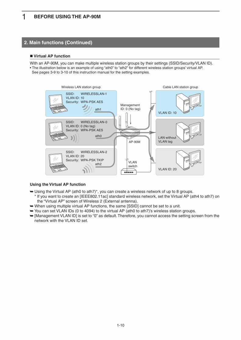
Virtual AP function
With an AP-90M, you can make multiple wireless station groups by their settings (SSID/Security/VLAN ID).• The illustration below is an example of using “ath0” to “ath2” for different wireless station groups’ virtual AP. See pages 3-9 to 3-10 of this instruction manual for the setting examples.
Using the Virtual AP function
Using the Virtual AP (ath0 to ath7)*, you can create a wireless network of up to 8 groups. ➥ * If you want to create an [IEEE802.11ac] standard wireless network, set the Virtual AP (ath4 to ath7) on
the “Virtual AP” screen of Wireless 2 (External antenna). When using multiple virtual AP functions, the same [SSID] cannot be set to a unit. ➥You can set VLAN IDs (0 to 4094) to the virtual AP (ath0 to ath7)’s wireless station groups. ➥ [Management VLAN ID] is set to “0” as default. Therefore, you cannot access the setting screen from the ➥network with the VLAN ID set.
2. Main functions (Continued)
SSID: WIRELESSLAN-0VLAN ID: 0 (No tag)Security: WPA-PSK AES
LAN without VLAN tag
SSID: WIRELESSLAN-2VLAN ID: 20Security: WPA-PSK TKIP
SSID: WIRELESSLAN-1VLAN ID: 10Security: WPA-PSK AES
VLAN ID: 10
VLAN ID: 20
ath0
ath2
ath1ManagementID: 0 (No tag)
Wireless LAN station group Cable LAN station group
VLANswitch
AP-90M
1 BEFORE USING THE AP-90M
1-11
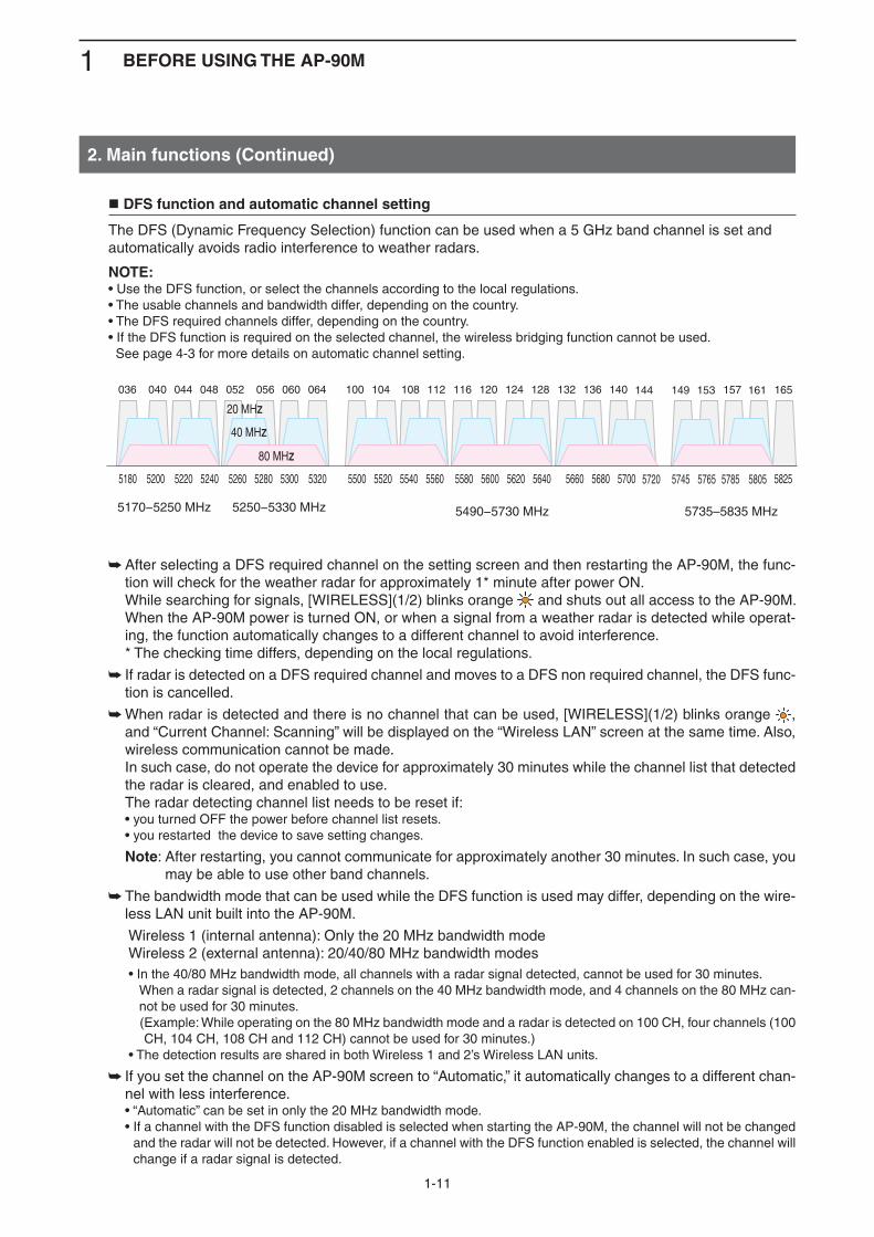
DFS function and automatic channel setting
The DFS (Dynamic Frequency Selection) function can be used when a 5 GHz band channel is set and automatically avoids radio interference to weather radars.
NOTE:• Use the DFS function, or select the channels according to the local regulations.• The usable channels and bandwidth differ, depending on the country.• The DFS required channels differ, depending on the country.• If the DFS function is required on the selected channel, the wireless bridging function cannot be used. See page 4-3 for more details on automatic channel setting.
After selecting a DFS required channel on the setting screen and then restarting the AP-90M, the func- ➥tion will check for the weather radar for approximately 1* minute after power ON.
While searching for signals, [WIRELESS](1/2) blinks orange and shuts out all access to the AP-90M. When the AP-90M power is turned ON, or when a signal from a weather radar is detected while operat-ing, the function automatically changes to a different channel to avoid interference.
* The checking time differs, depending on the local regulations.
If radar is detected on a DFS required channel and moves to a DFS non required channel, the DFS func- ➥tion is cancelled.
When radar is detected and there is no channel that can be used, [WIRELESS](1/2) blinks orange ➥ , and “Current Channel: Scanning” will be displayed on the “Wireless LAN” screen at the same time. Also, wireless communication cannot be made.
In such case, do not operate the device for approximately 30 minutes while the channel list that detected the radar is cleared, and enabled to use.
The radar detecting channel list needs to be reset if: • you turned OFF the power before channel list resets. • you restarted the device to save setting changes.
Note: After restarting, you cannot communicate for approximately another 30 minutes. In such case, you may be able to use other band channels.
The bandwidth mode that can be used while the DFS function is used may differ, depending on the wire- ➥less LAN unit built into the AP-90M.
Wireless 1 (internal antenna): Only the 20 MHz bandwidth mode Wireless 2 (external antenna): 20/40/80 MHz bandwidth modes • In the 40/80 MHz bandwidth mode, all channels with a radar signal detected, cannot be used for 30 minutes. When a radar signal is detected, 2 channels on the 40 MHz bandwidth mode, and 4 channels on the 80 MHz can-
not be used for 30 minutes. ( Example: While operating on the 80 MHz bandwidth mode and a radar is detected on 100 CH, four channels (100
CH, 104 CH, 108 CH and 112 CH) cannot be used for 30 minutes.) • The detection results are shared in both Wireless 1 and 2’s Wireless LAN units.
If you set the channel on the AP-90M screen to “Automatic,” it automatically changes to a different chan- ➥nel with less interference.
• “Automatic” can be set in only the 20 MHz bandwidth mode. • If a channel with the DFS function disabled is selected when starting the AP-90M, the channel will not be changed
and the radar will not be detected. However, if a channel with the DFS function enabled is selected, the channel will change if a radar signal is detected.
2. Main functions (Continued)
5180 5200 5220 5240 5260 5280 5300 5320 5500 5520 5540 5560 5580 5600 5620 5640 5660 5680 5700
5490−5730 MHz5250−5330 MHz 5170−5250 MHz
5720 5745 5765 5785 5805 5825
5735–5835 MHz
036
20 MHz
40 MHz
80 MHz
040 044 048 052 056 060 064 100 104 108 112 116 120 124 128 132 136 140 144 149 153 157 161 165

1 BEFORE USING THE AP-90M
1-12
WPS function
With the function that the “Wi-Fi Alliance” proposed, SSID and Security (WPA-PSK/WPA2-PSK) can automati-cally be set to the AP-90M and the wireless LAN station that supports the WPS (Wi-Fi Protected Setup) function.• To automatically set it and start the WPS function, you can select either of the following methods.
Using the [WPS] button ( ➥ +p.1-3) that is located on the back of the AP-90M. (Push Button)
Setting the communicator’s PIN code. ➥ (PIN (Personal Identification Number)) • See Section 2 (+p.2-11) for examples on setting the SSID and Shared Key to the wireless LAN station
using the WPS function. • See Section 3 (+p.3-8) for an example on automatically setting with the WPS function.
Using the WPS functionUse a wireless LAN station that supports the WPS function. ➥ If your wireless LAN station has no [WPS] button, use the application that supports WPS, or a regular ➥wireless network connection using Windows (Windows 7 or later). Enable the virtual AP and select the “Interface (ath0 to ath7)” to automatically set the virtual AP using the ➥WPS function. (+p.2-11)
If you select an invalid virtual AP for “Interface,” the [WPS] button cannot be used. (+p.1-3)
2. Main functions (Continued)
q Push [WPS]
Wireless LAN station
DC GNDLANUSBWPS
w Push [WPS]
Using the WPS function
WirelessLAN station
q Connect the cabled LAN station.w Access the setting screen.e Set the SSID and Shared Key.
r Start the connection software.t Select the “SSID” of the virtual AP.y Select the encryption.
Not using the WPS function
AP-90MAP-90M
2-1
1. About the PC to use ................................................................................................................................2-2 Setting by connecting the cable LAN station .........................................................................................2-2 Setting by connecting the wireless LAN station .....................................................................................2-22. Setting the static IP address to a PC .....................................................................................................2-33. Connecting to the PC ..............................................................................................................................2-4 Using a cable LAN station .....................................................................................................................2-4 Using a wireless LAN station .................................................................................................................2-54. Accessing the setting screen .................................................................................................................2-75. Changing the IP address .........................................................................................................................2-86. Manually entering the SSID and Encryption .........................................................................................2-9 Manually entering the SSID ...................................................................................................................2-9 Manually entering the Encryption ..........................................................................................................2-107. Assigning the automatic SSID and PSK in the WPS function .............................................................2-11 Enabling the WPS function ....................................................................................................................2-11 Automatically setting the wireless LAN by using the WPS function .......................................................2-12
INSTALLATION GUIDE 2
2 INSTALLATION GUIDE
2-2
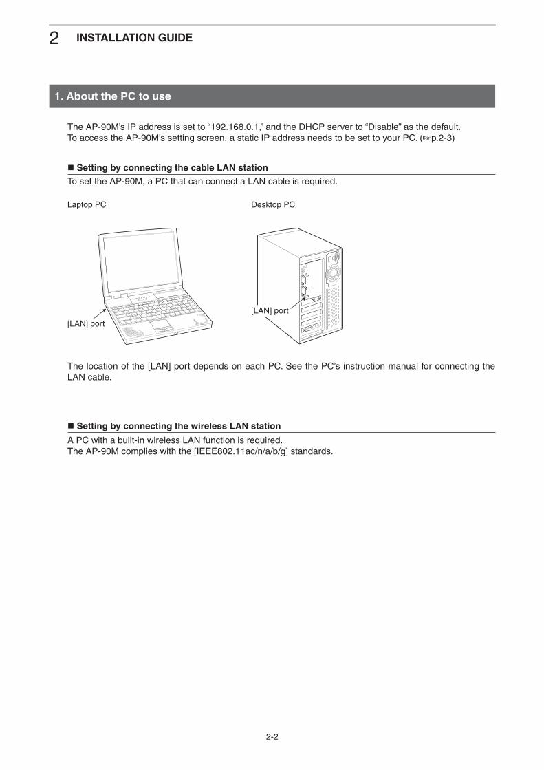
The AP-90M’s IP address is set to “192.168.0.1,” and the DHCP server to “Disable” as the default.To access the AP-90M’s setting screen, a static IP address needs to be set to your PC. (+p.2-3)
1. About the PC to use
Setting by connecting the cable LAN stationTo set the AP-90M, a PC that can connect a LAN cable is required.
Laptop PC Desktop PC
The location of the [LAN] port depends on each PC. See the PC’s instruction manual for connecting the LAN cable.
Setting by connecting the wireless LAN station
A PC with a built-in wireless LAN function is required.The AP-90M complies with the [IEEE802.11ac/n/a/b/g] standards.
[LAN] port
[LAN] port

2 INSTALLATION GUIDE
2-3
Click [Start] (Windows logo) and then click [Control Panel].1
In the [Control Panel] window, click [Network and Internet] and then click [Network and Sharing Center].2
Click [Change adapter settings].3
Right-click [Local Area Connection] (cable LAN station) or [Wireless Network Connection] (wireless LAN station), and then click [Properties] in the displayed menu list.
4
If the [User Account Control] message appears, click [Yes] to continue.5
In the [Local Area Connection Properties] (for a cable LAN station) or the [Wireless Network Connec-tion Properties] (for a wireless LAN station) screen, select “Internet Protocol Version 4 (TCP/IPv4),” and then click [Properties].The “Internet Protocol Version 4 (TCP/IPv4) Properties” screen is displayed.
6
Select “Use the following IP address” and enter the IP address (example: 192.168.0.100) and the Subnet mask (example: 255.255.255.0), and then click [OK].
7
Close the window.8
The following procedures describe how to set the a static IP address (example: 192.168.0.100), based on Microsoft Windows 7.The AP-90M’s IP address is set to “192.168.0.1,” and the DHCP server to “Disable” as the default.
2. Setting the static IP address to a PC
q Right-click
w Click
w Enter
e Click
q Select
If necessary, change the PC’s IP address after setting up the AP-90M.

2 INSTALLATION GUIDE
2-4
If you are connecting the AP-90M using its default settings, disconnect the network from your PC.
3. Connecting to the PC
Using a cable LAN station
Turn ON the AP-90M and the PC (cable LAN).Make sure the devices are turned OFF when you connect them to together.
R WARNING!To prevent electrical shock, television interference (TVI), broadcast interference (BCI) and other prob-lems, ground the AP-90M through the ground terminal.
NEVER connect the ground terminal to a gas or electric pipe. This may result in an electrical shock or cause a fire or explosion.
AP-90M
WIRELESS ACCESS POINT
Ground wire(User supplied)
Ground terminal
Power adapter(User supplied)
AC outlet
AP-90M
PC
To the ground terminal
To the DC jack
To the [LAN] port
LAN cable(User supplied:Category 5e or higher)(Example: 192.168.0.100)
(Default: 192.168.0.1)
Indication check
[POWER]: Green [LAN]: Green/Orange*� [WIRELESS1]: Orange[WIRELESS2]: Orange
*Indication differs, depending on the status
(+Continued on the next page)

2 INSTALLATION GUIDE
2-5
3. Connecting to the PC (Continued)
Using a wireless LAN station
Turn ON the AP-90M and the PC (cable LAN).
R WARNING!To prevent electrical shock, television interference (TVI), broadcast interference (BCI) and other problems, ground the AP-90M through the ground terminal.
NEVER connect the ground terminal to a gas or electric pipe. This may result in an electrical shock or cause a fire or explosion.
AP-90M
WIRELESS ACCESS POINT
Ground wire(User supplied)
Ground terminal
Power adapter(User supplied)
AC outlet
AP-90M
Wireless LAN PC
To the ground terminal
To the DC jack
(Default: 192.168.0.1)
Indication check
[POWER]: Green [LAN]: OFF [WIRELESS1]: Orange[WIRELESS2]: Orange
Turn the ON the AP-90M’s power and then start a PC (wireless LAN) that is equipped with a wireless LAN system.
1
Click the wireless network connection icon.• It may take a few minutes until the icon appears.
2
Click
(+Continued on the next page)
2 INSTALLATION GUIDE
2-6
3. Connecting to the PC
Using a wireless LAN station (Continued)
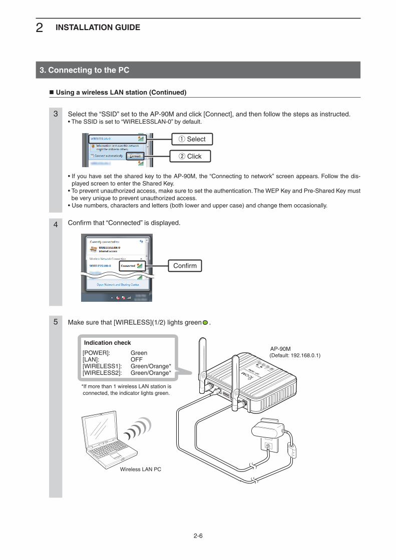
Select the “SSID” set to the AP-90M and click [Connect], and then follow the steps as instructed.• The SSID is set to “WIRELESSLAN-0” by default.
• If you have set the shared key to the AP-90M, the “Connecting to network” screen appears. Follow the dis-played screen to enter the Shared Key.
• To prevent unauthorized access, make sure to set the authentication. The WEP Key and Pre-Shared Key must be very unique to prevent unauthorized access.
• Use numbers, characters and letters (both lower and upper case) and change them occasionally.
3
Confirm that “Connected” is displayed.4
Make sure that [WIRELESS](1/2) lights green .5
w Click
q Select
Confirm
AP-90M
WIRELESS ACCESS POINT
Indication check
[POWER]: Green [LAN]: OFF [WIRELESS1]: Green/Orange*[WIRELESS2]: Green/Orange*
*If more than 1 wireless LAN station is connected, the indicator lights green.
AP-90M
Wireless LAN PC
(Default: 192.168.0.1)
2 INSTALLATION GUIDE
2-7
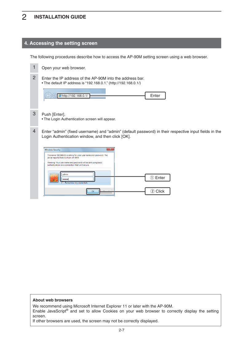
Open your web browser.1
Enter the IP address of the AP-90M into the address bar.• The default IP address is “192.168.0.1.” (http://192.168.0.1/)
2
Push [Enter].• The Login Authentication screen will appear.
3
Enter “admin” (fixed username) and “admin” (default password) in their respective input fields in the Login Authentication window, and then click [OK].
4
The following procedures describe how to access the AP-90M setting screen using a web browser.
4. Accessing the setting screen
http://192.168.0.1/ Enter
w Click
q Enter
About web browsersWe recommend using Microsoft Internet Explorer 11 or later with the AP-90M.Enable JavaScript® and set to allow Cookies on your web browser to correctly display the setting screen.If other browsers are used, the screen may not be correctly displayed.
2 INSTALLATION GUIDE
2-8
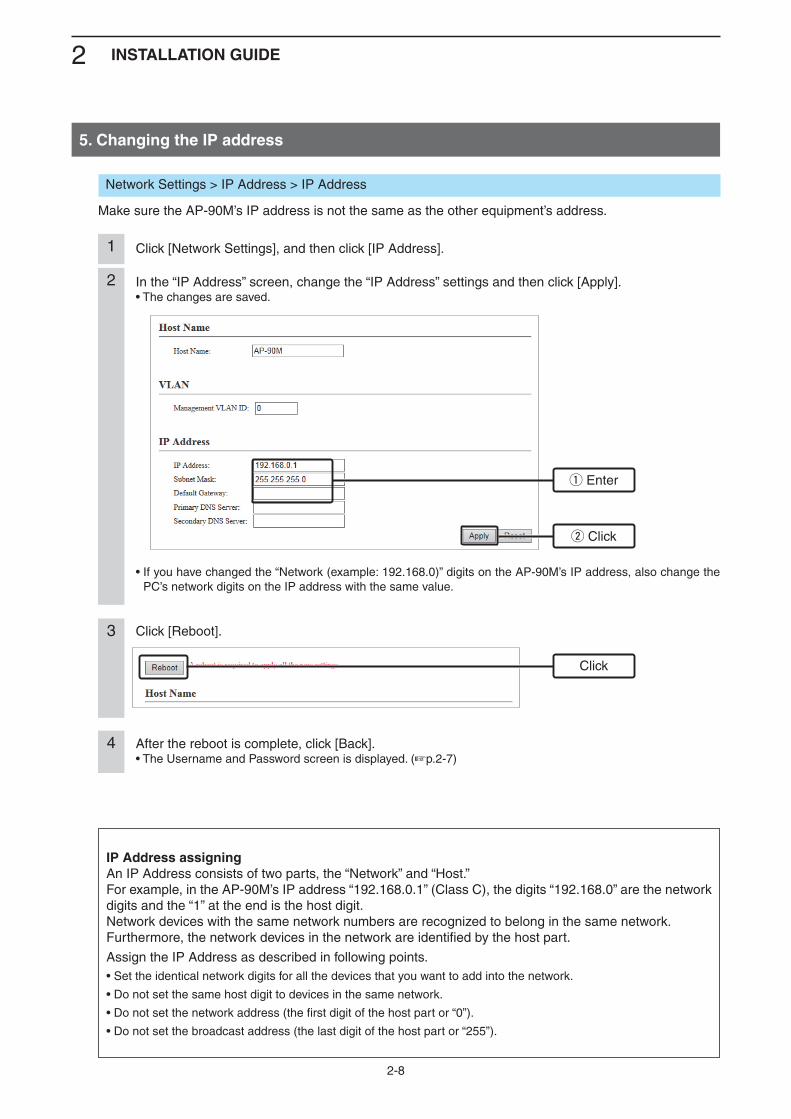
In the “IP Address” screen, change the “IP Address” settings and then click [Apply].• The changes are saved.
2
Click [Reboot].3
After the reboot is complete, click [Back].• The Username and Password screen is displayed. (+p.2-7)
4
Click [Network Settings], and then click [IP Address].1
5. Changing the IP address
w Click
q Enter
Click
IP Address assigningAn IP Address consists of two parts, the “Network” and “Host.”For example, in the AP-90M’s IP address “192.168.0.1” (Class C), the digits “192.168.0” are the network digits and the “1” at the end is the host digit.Network devices with the same network numbers are recognized to belong in the same network.Furthermore, the network devices in the network are identified by the host part.
Assign the IP Address as described in following points.• Set the identical network digits for all the devices that you want to add into the network.
• Do not set the same host digit to devices in the same network.
• Do not set the network address (the first digit of the host part or “0”).
• Do not set the broadcast address (the last digit of the host part or “255”).
• If you have changed the “Network (example: 192.168.0)” digits on the AP-90M’s IP address, also change the PC’s network digits on the IP address with the same value.
Network Settings > IP Address > IP Address
Make sure the AP-90M’s IP address is not the same as the other equipment’s address.
2 INSTALLATION GUIDE
2-9
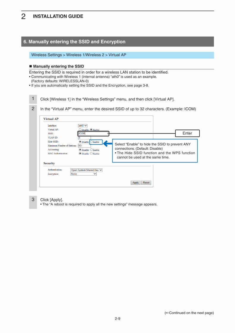
In the “Virtual AP” menu, enter the desired SSID of up to 32 characters. (Example: ICOM)2
Click [Apply].• The “A reboot is required to apply all the new settings” message appears.
3
Click [Wireless 1] in the “Wireless Settings” menu, and then click [Virtual AP].1
6. Manually entering the SSID and Encryption
Enter
Wireless Settings > Wireless 1/Wireless 2 > Virtual AP
Manually entering the SSIDEntering the SSID is required in order for a wireless LAN station to be identified.• Communicating with Wireless 1 (internal antenna) “ath0” is used as an example. (Factory defaults: WIRELESSLAN-0)• If you are automatically setting the SSID and the Encryption, see page 3-8.
Select “Enable” to hide the SSID to prevent ANY connections. (Default: Disable)• The Hide SSID function and the WPS function
cannot be used at the same time.
(+Continued on the next page)
2 INSTALLATION GUIDE
2-10
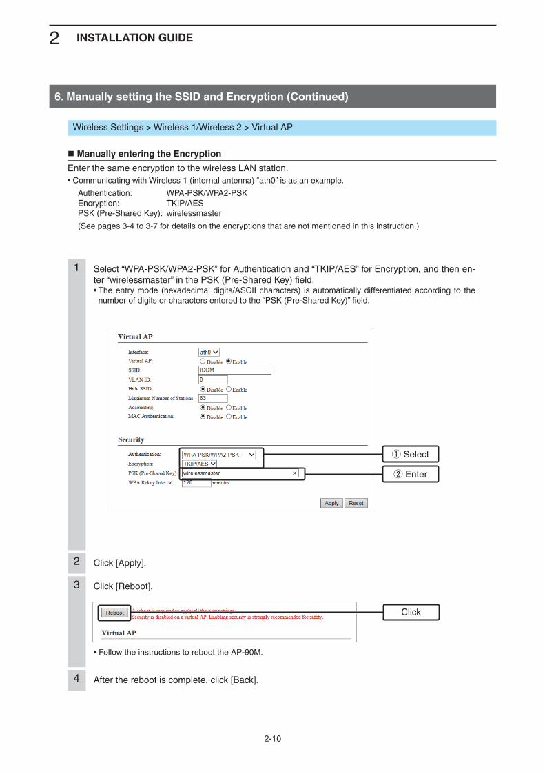
Select “WPA-PSK/WPA2-PSK” for Authentication and “TKIP/AES” for Encryption, and then en-ter “wirelessmaster” in the PSK (Pre-Shared Key) field.• The entry mode (hexadecimal digits/ASCII characters) is automatically differentiated according to the
number of digits or characters entered to the “PSK (Pre-Shared Key)” field.
1
6. Manually setting the SSID and Encryption (Continued)
Wireless Settings > Wireless 1/Wireless 2 > Virtual AP
Manually entering the Encryption
Enter the same encryption to the wireless LAN station.• Communicating with Wireless 1 (internal antenna) “ath0” is as an example.
Authentication: WPA-PSK/WPA2-PSK Encryption: TKIP/AES PSK (Pre-Shared Key): wirelessmaster
(See pages 3-4 to 3-7 for details on the encryptions that are not mentioned in this instruction.)
w Enter
q Select
Click [Apply].2
Click [Reboot].
• Follow the instructions to reboot the AP-90M.
3
After the reboot is complete, click [Back].4
Click
2 INSTALLATION GUIDE
2-11
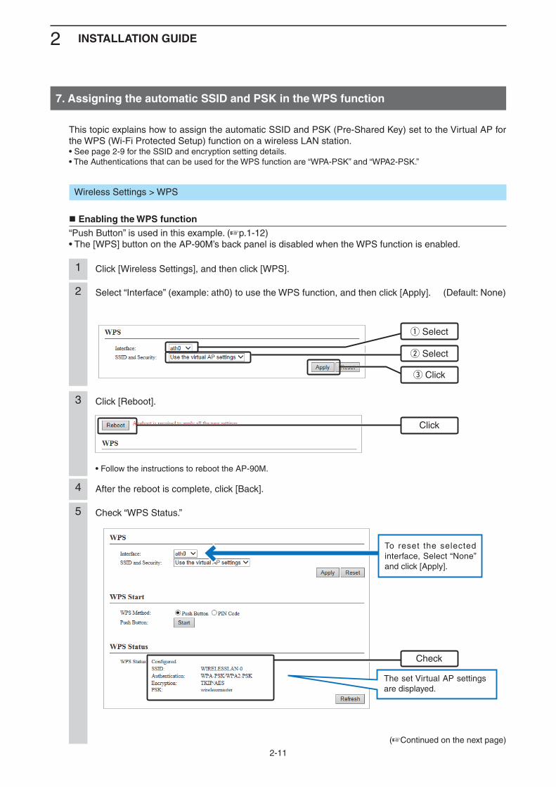
Select “Interface” (example: ath0) to use the WPS function, and then click [Apply]. (Default: None)2
Click [Wireless Settings], and then click [WPS].1
7. Assigning the automatic SSID and PSK in the WPS function
q Select
w Select
e Click
Wireless Settings > WPS
Enabling the WPS function“Push Button” is used in this example. (+p.1-12)• The [WPS] button on the AP-90M’s back panel is disabled when the WPS function is enabled.
This topic explains how to assign the automatic SSID and PSK (Pre-Shared Key) set to the Virtual AP for the WPS (Wi-Fi Protected Setup) function on a wireless LAN station.• See page 2-9 for the SSID and encryption setting details.• The Authentications that can be used for the WPS function are “WPA-PSK” and “WPA2-PSK.”
Click [Reboot].
• Follow the instructions to reboot the AP-90M.
3
After the reboot is complete, click [Back].4
Click
(+Continued on the next page)
5 Check “WPS Status.”
Check
The set Virtual AP settings are displayed.
To reset the selected interface, Select “None” and click [Apply].
2 INSTALLATION GUIDE
2-12
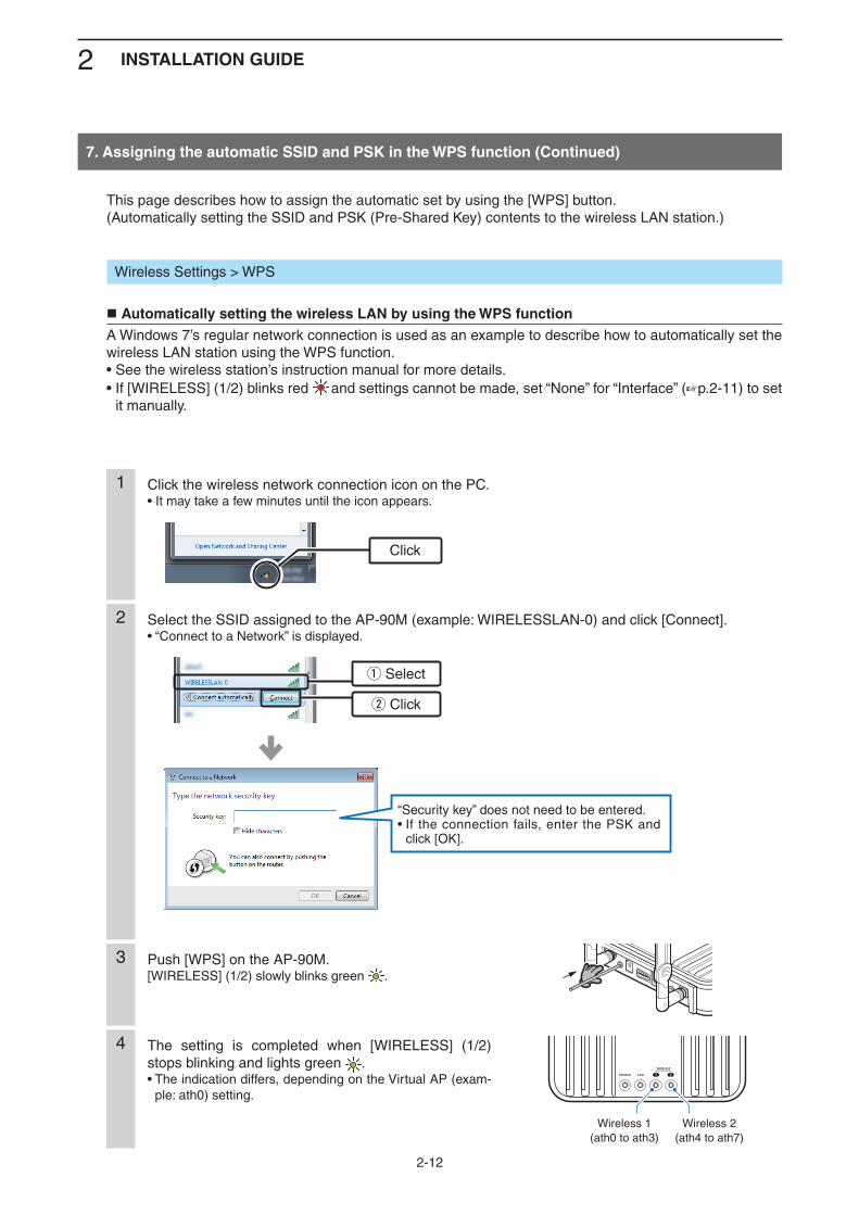
Push [WPS] on the AP-90M.[WIRELESS] (1/2) slowly blinks green .
3
Click the wireless network connection icon on the PC.• It may take a few minutes until the icon appears.
1
7. Assigning the automatic SSID and PSK in the WPS function (Continued)
Wireless Settings > WPS
Automatically setting the wireless LAN by using the WPS functionA Windows 7’s regular network connection is used as an example to describe how to automatically set the wireless LAN station using the WPS function.• See the wireless station’s instruction manual for more details.• If [WIRELESS] (1/2) blinks red and settings cannot be made, set “None” for “Interface” (+p.2-11) to set
it manually.
This page describes how to assign the automatic set by using the [WPS] button.(Automatically setting the SSID and PSK (Pre-Shared Key) contents to the wireless LAN station.)
Click
Select the SSID assigned to the AP-90M (example: WIRELESSLAN-0) and click [Connect].• “Connect to a Network” is displayed.
2
w Click
q Select
The setting is completed when [WIRELESS] (1/2) stops blinking and lights green .• The indication differs, depending on the Virtual AP (exam-
ple: ath0) setting.
4
Wireless 1(ath0 to ath3)
Wireless 2(ath4 to ath7)
“Security key” does not need to be entered.• If the connection fails, enter the PSK and
click [OK].
3-1
CONNECTING TO A WIRELESS LAN 3 (BASIC)
1. Disabling the wireless communication ..................................................................................................3-2 Disabling the Wireless Unit .....................................................................................................................3-22. [IEEE802.11ac] standard (5 GHz band) communication .......................................................................3-3 Communicating in the 80 MHz bandwidth ..............................................................................................3-33. Setting the “WEP RC4” encryption ..........................................................................................................3-4 About the WEP Key ................................................................................................................................3-4 ASCII characters and hexadecimal digits ...............................................................................................3-4 Entering the WEP Key with hexadecimal digits ......................................................................................3-5 Entering the WEP Key with ASCII characters .........................................................................................3-6 Generating the WEP Key ........................................................................................................................3-74. Automatically setting the SSID and Shared Key ....................................................................................3-8 Enabling the WPS function .....................................................................................................................3-85. Setting the Virtual AP ...............................................................................................................................3-96. Setting the Wireless Bridging function ...................................................................................................3-11 Using Wireless 1 (internal antenna) ........................................................................................................3-12 Using Wireless 2 (External antenna) ......................................................................................................3-14 Setting the Master unit ............................................................................................................................3-15 Setting the wireless bridging function to the AP-90M for the RS-AP3 management ..............................3-187. Setting the MAC Address Filtering..........................................................................................................3-19
3 CONNECTING TO A WIRELESS LAN (BASIC)
3-2
1. Disabling the wireless communication
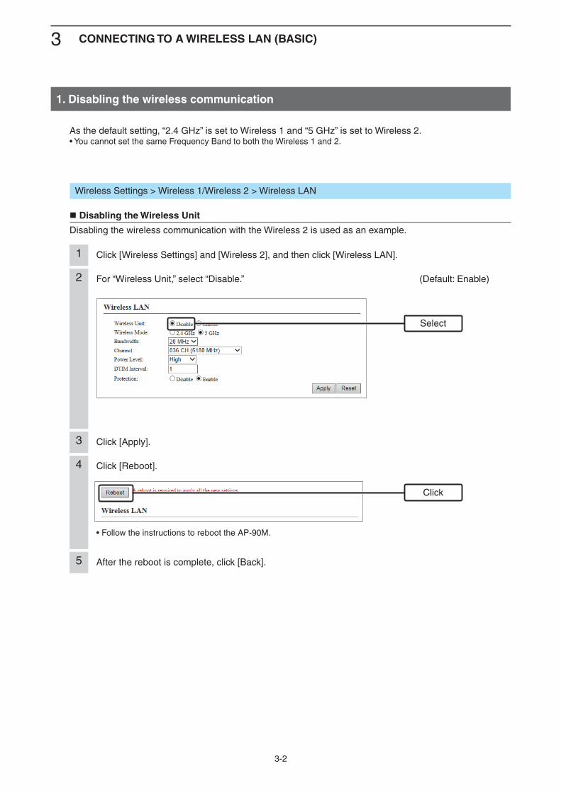
For “Wireless Unit,” select “Disable.” (Default: Enable)2
Click [Wireless Settings] and [Wireless 2], and then click [Wireless LAN].1
Select
Wireless Settings > Wireless 1/Wireless 2 > Wireless LAN
Disabling the Wireless Unit
Disabling the wireless communication with the Wireless 2 is used as an example.
As the default setting, “2.4 GHz” is set to Wireless 1 and “5 GHz” is set to Wireless 2.• You cannot set the same Frequency Band to both the Wireless 1 and 2.
Click [Reboot].
• Follow the instructions to reboot the AP-90M.
4
After the reboot is complete, click [Back].5
Click
Click [Apply].3
3 CONNECTING TO A WIRELESS LAN (BASIC)
3-3
2. [IEEE802.11ac] standard (5 GHz band) communication
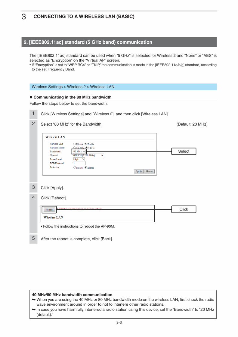
Select “80 MHz” for the Bandwidth. (Default: 20 MHz)2
Click [Wireless Settings] and [Wireless 2], and then click [Wireless LAN].1
Select
Wireless Settings > Wireless 2 > Wireless LAN
Communicating in the 80 MHz bandwidth
Follow the steps below to set the bandwidth.
The [IEEE802.11ac] standard can be used when “5 GHz” is selected for Wireless 2 and “None” or “AES” is selected as “Encryption” on the “Virtual AP” screen.• If “Encryption” is set to “WEP RC4” or “TKIP,” the communication is made in the [IEEE802.11a/b/g] standard, according
to the set Frequency Band.
Click [Reboot].
• Follow the instructions to reboot the AP-90M.
4
After the reboot is complete, click [Back].5
Click
Click [Apply].3
40 MHz/80 MHz bandwidth communication When you are using the 40 MHz or 80 MHz bandwidth mode on the wireless LAN, first check the radio ➥wave environment around in order to not to interfere other radio stations. In case you have harmfully interfered a radio station using this device, set the “Bandwidth” to “20 MHz ➥
(default).”

3 CONNECTING TO A WIRELESS LAN (BASIC)
3-4
There are three ways to configure the “WEP RC4” encryption.Directly entering the hexadecimal encryption keys. ( ➥ +p.3-5)Directly entering the ASCII lettered encryption keys. ( ➥ +p.3-6)Generating the encryption keys according to the entered “Key Generator” character strings. ➥ (+p.3-7)
• “Encryption” is not set as a default.• If you cannot set “WEP RC4,” the WPS function may be set to the Virtual AP (ath0 to ath7) used. (+p.2-11)• See page 2-11 for the “WPA-PSK (TKIP)/(AES)” setting examples.
3. Setting the “WEP RC4” encryption
About the WEP KeyDepending on the “Encryption” setting and the bit number in the parenthesis, the number of digits or char-acters that can be entered differs.The entry mode (hexadecimal digits/ASCII characters) is automatically selected according to the number of entered digits or characters.
ASCII characters and hexadecimal digitsIf “Encryption” cannot be set for the communicator’s entry mode, enter characters, according to the follow-ing table.For example, “4153434949” (10 hexadecimal digits) in the hexadecimal code will be “ASCII” (5 numbers and letters) in the ASCII characters.
AuthenticationEncryption
Entry mode
Open System Shared Key Hexadecimal ASCII
✓ None (Default) — —
✓ ✓ WEP RC4 64 (40) 10 digits 5 characters
✓ ✓ WEP RC4 (128) 26 digits 13 characters
✓ ✓ WEP RC4 152 (128) 32 digits 16 characters
ASCII ! ” # $ % & ’ ( ) * + , - . /
Hexadecimal 20 21 22 23 24 25 26 27 28 29 2a 2b 2c 2d 2e 2f
ASCII 0 1 2 3 4 5 6 7 8 9 : ; < = > ?
Hexadecimal 30 31 32 33 34 35 36 37 38 39 3a 3b 3c 3d 3e 3f
ASCII @ A B C D E F G H I J K L M N O
Hexadecimal 40 41 42 43 44 45 46 47 48 49 4a 4b 4c 4d 4e 4f
ASCII P Q R S T U V W X Y Z [ \ ] ^ _
Hexadecimal 50 51 52 53 54 55 56 57 58 59 5a 5b 5c 5d 5e 5f
ASCII ` a b c d e f g h i j k l m n o
Hexadecimal 60 61 62 63 64 65 66 67 68 69 6a 6b 6c 6d 6e 6f
ASCII p q r s t u v w x y z { | } ~
Hexadecimal 70 71 72 73 74 75 76 77 78 79 7a 7b 7c 7d 7e
To prevent unauthorized accessYou must carefully chose the WEP Key, and change it occasionally. Choose one that is not easy to guess and use numbers, characters and letters (both lower and upper case).
3 CONNECTING TO A WIRELESS LAN (BASIC)
3-5
3. Setting the “WEP RC4” encryption (Continued)
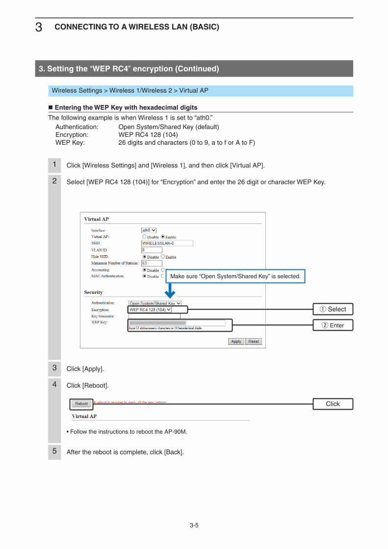
Select [WEP RC4 128 (104)] for “Encryption” and enter the 26 digit or character WEP Key.2
Wireless Settings > Wireless 1/Wireless 2 > Virtual AP
Entering the WEP Key with hexadecimal digits
The following example is when Wireless 1 is set to “ath0.” Authentication: Open System/Shared Key (default) Encryption: WEP RC4 128 (104) WEP Key: 26 digits and characters (0 to 9, a to f or A to F)
w Enter
q Select
Click [Apply].3
Click [Reboot].
• Follow the instructions to reboot the AP-90M.
4
After the reboot is complete, click [Back].5
Click
Click [Wireless Settings] and [Wireless 1], and then click [Virtual AP].1
Make sure “Open System/Shared Key” is selected.
3 CONNECTING TO A WIRELESS LAN (BASIC)
3-6
3. Setting the “WEP RC4” encryption (Continued)
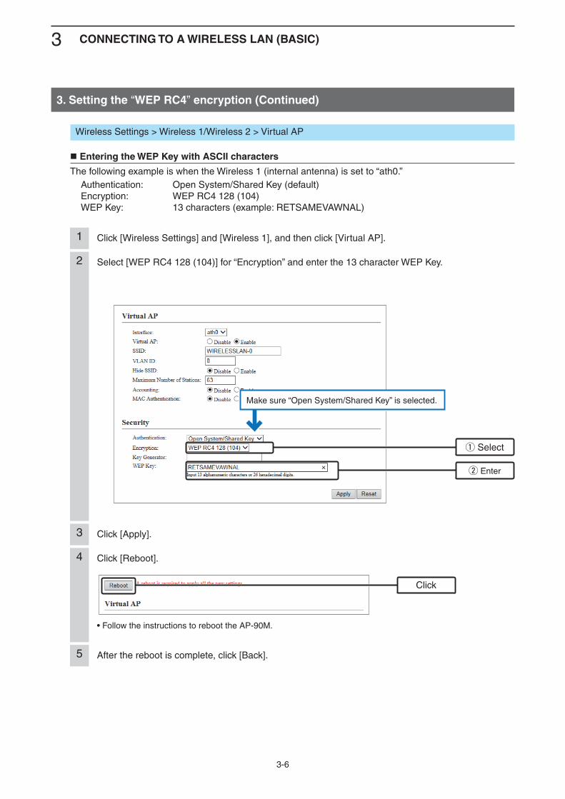
Select [WEP RC4 128 (104)] for “Encryption” and enter the 13 character WEP Key.2
Wireless Settings > Wireless 1/Wireless 2 > Virtual AP
Entering the WEP Key with ASCII characters
The following example is when the Wireless 1 (internal antenna) is set to “ath0.” Authentication: Open System/Shared Key (default) Encryption: WEP RC4 128 (104) WEP Key: 13 characters (example: RETSAMEVAWNAL)
w Enter
q Select
Click [Apply].3
Click [Reboot].
• Follow the instructions to reboot the AP-90M.
4
After the reboot is complete, click [Back].5
Click
Click [Wireless Settings] and [Wireless 1], and then click [Virtual AP].1
Make sure “Open System/Shared Key” is selected.

3 CONNECTING TO A WIRELESS LAN (BASIC)
3-7
3. Setting the “WEP RC4” encryption (Continued)
Select [WEP RC4 128 (104)] for “Encryption” and enter the desired character string of up to 31 characters into “Key Generator.”
2
Wireless Settings > Wireless 1/Wireless 2 > Virtual AP
Generating the WEP Key
The following example is when Wireless 1 is set to “ath0.” Authentication: Open System/Shared Key (default) Encryption: WEP RC4 128 (104) Key Generator: Desired character string of up to 31 characters (example: ICOM)
w Enter
q Select
Click [Apply].3
Click [Reboot].
• Follow the instructions to reboot the AP-90M.
4
After the reboot is complete, click [Back].5
Click
Click [Wireless Settings] and [Wireless 1], and then click [Virtual AP].1
The generated WEP Key is displayed.
About the Key GeneratorThe Key Generator is not compatible with other than Icom products. ➥Enter the desired characters to automatically generate the WEP key into the text box. ➥The generated digits or characters differ, depending on the “Encryption” setting. ➥
Make sure “Open System/Shared Key” is selected.

3 CONNECTING TO A WIRELESS LAN (BASIC)
3-8
Select the Virtual AP to use the WPS function. (Example: ath0) (default: None)2
Select [Automatic Setting by WPS] for “SSID and Security” and then click [Apply].“A reboot is required to apply all the new settings.” is displayed.• To use the SSID and Shared Key that are manually set to the AP-90M, select “Use the Virtual AP set-
tings.” (default)
3
Click [Wireless Settings], and then click [WPS].1
4. Automatically setting the SSID and Shared Key
Select
Wireless Settings > WPS
Enabling the WPS function
The “Push Button” method is used an example. (+p.1-12)• If you enable the WPS function, the [WPS] button on the AP-90M’s back panel is enabled. Changing “SSID” and “Security” on the “Virtual AP” screen (example: ath0) will be disabled.
Using the WPS (Wi-Fi Protected Setup) function, you can use the SSID and Shared Key that are automati-cally generated in the AP-90M and the PC (WPS compatible).• To manually set the SSID and Security without using the WPS function, see page 2-9.
Click [Reboot].
• Follow the instructions to reboot the AP-90M.
4
After the reboot is complete, click [Back].5
Click
q Select
w Click
3 CONNECTING TO A WIRELESS LAN (BASIC)
3-9
5. Setting the Virtual AP
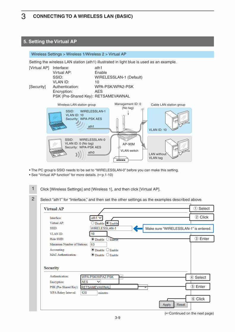
Click [Wireless Settings] and [Wireless 1], and then click [Virtual AP].1
(+Continued on the next page)
Select “ath1” for “Interface,” and then set the other settings as the examples described above.2
q Select
w Click
e Enter
r Select
t Enter
y Click
Make sure “WIRELESSLAN-1” is entered.
Wireless Settings > Wireless 1/Wireless 2 > Virtual AP
Setting the wireless LAN station (ath1) illustrated in light blue is used as an example.
[Virtual AP] Interface: ath1 Virtual AP: Enable SSID: WIRELESSLAN-1 (Default) VLAN ID: 10[Security] Authentication: WPA-PSK/WPA2-PSK Encryption: AES PSK (Pre-Shared Key): RETSAMEVAWNAL
• The PC group’s SSID needs to be set to “WIRELESSLAN-0” before you can make this setting.• See “Virtual AP function” for more details. (+p.1-10)
SSID: WIRELESSLAN-0VLAN ID: 0 (No tag)Security: WPA-PSK AES
LAN without VLAN tag
SSID: WIRELESSLAN-1VLAN ID: 10Security: WPA-PSK AES
VLAN ID: 10
ath0
ath1
Management ID: 0(No tag)
Wireless LAN station group Cable LAN station group
VLAN switch
AP-90M
3 CONNECTING TO A WIRELESS LAN (BASIC)
3-10
5. Setting the Virtual AP (Continued)
Wireless Settings > Wireless 1/Wireless 2 > Virtual AP
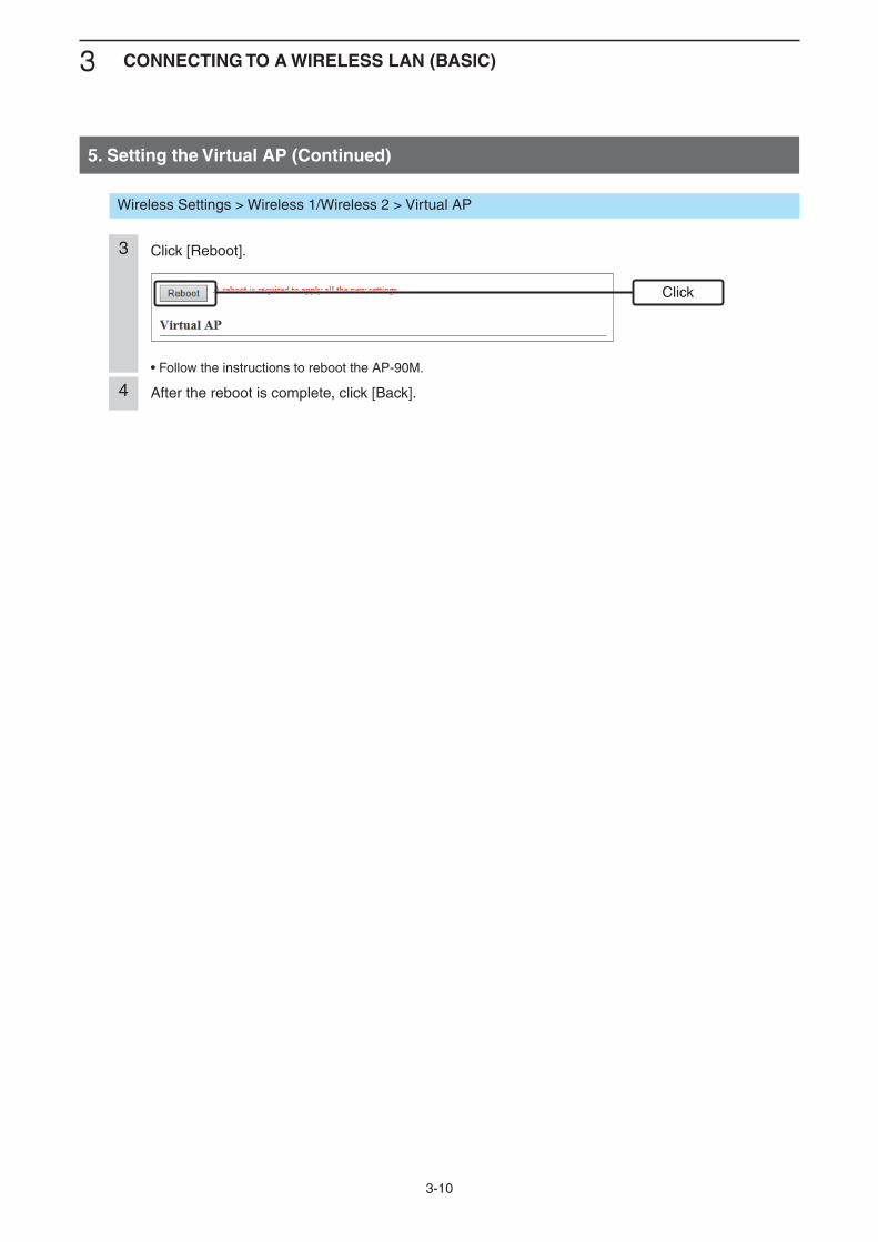
Click [Reboot].
• Follow the instructions to reboot the AP-90M.
3
After the reboot is complete, click [Back].4
Click
3 CONNECTING TO A WIRELESS LAN (BASIC)
3-11
6. Setting the Wireless Bridging function
Using Wireless 1 (internal antenna) (+p.3-12)• You need to set the AP’s “BSSID” to each access point.• You need to set the same channel and the special Shared Key for the Wireless Bridging function to each access point.
Using the Wireless 2 (external antenna) (+p.3-14)• Check the client’s “BSSID,” which is displayed on the “Wireless Bridging (WBR)” screen, and then set the BBSID to
the master’s “Peer BSSID.”• You must set “SSID,” which is set to the master’s virtual AP (ath4) and “Encryption,” to the client.
Management using the RS-AP3 (+p.3-18)When you manage the AP-90M settings using the RS-AP3 access point management tool, set the “Wireless Bridging” function on the AP-90M’s setting screen (Wireless 1/Wireless 2) to be able to communicate.
3 CONNECTING TO A WIRELESS LAN (BASIC)
3-12
00-90-C7-00-00-02
6. Setting the Wireless Bridging function (Continued)
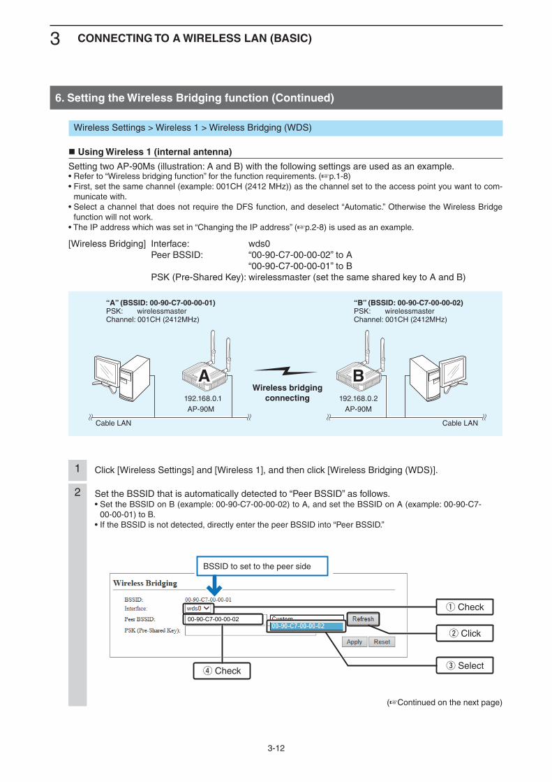
Click [Wireless Settings] and [Wireless 1], and then click [Wireless Bridging (WDS)].1
(+Continued on the next page)
Set the BSSID that is automatically detected to “Peer BSSID” as follows.• Set the BSSID on B (example: 00-90-C7-00-00-02) to A, and set the BSSID on A (example: 00-90-C7-
00-00-01) to B.• If the BSSID is not detected, directly enter the peer BSSID into “Peer BSSID.”
2
q Check
w Click
e Selectr Check
BSSID to set to the peer side
Wireless Settings > Wireless 1 > Wireless Bridging (WDS)
Using Wireless 1 (internal antenna)
Setting two AP-90Ms (illustration: A and B) with the following settings are used as an example.• Refer to “Wireless bridging function” for the function requirements. (+p.1-8)• First, set the same channel (example: 001CH (2412 MHz)) as the channel set to the access point you want to com-
municate with.• Select a channel that does not require the DFS function, and deselect “Automatic.” Otherwise the Wireless Bridge
function will not work.• The IP address which was set in “Changing the IP address” (+p.2-8) is used as an example.
[Wireless Bridging] Interface: wds0 Peer BSSID: “00-90-C7-00-00-02” to A “00-90-C7-00-00-01” to B PSK (Pre-Shared Key): wirelessmaster (set the same shared key to A and B)
* Values are set as example
Wireless bridgingconnecting
AA BB
Cable LAN Cable LAN
“A” (BSSID: 00-90-C7-00-00-01)PSK: wirelessmasterChannel: 001CH (2412MHz)
192.168.0.1 192.168.0.2
“B” (BSSID: 00-90-C7-00-00-02)PSK: wirelessmasterChannel: 001CH (2412MHz)
AP-90M AP-90M
3 CONNECTING TO A WIRELESS LAN (BASIC)
3-13
6. Setting the Wireless Bridging function (Continued)
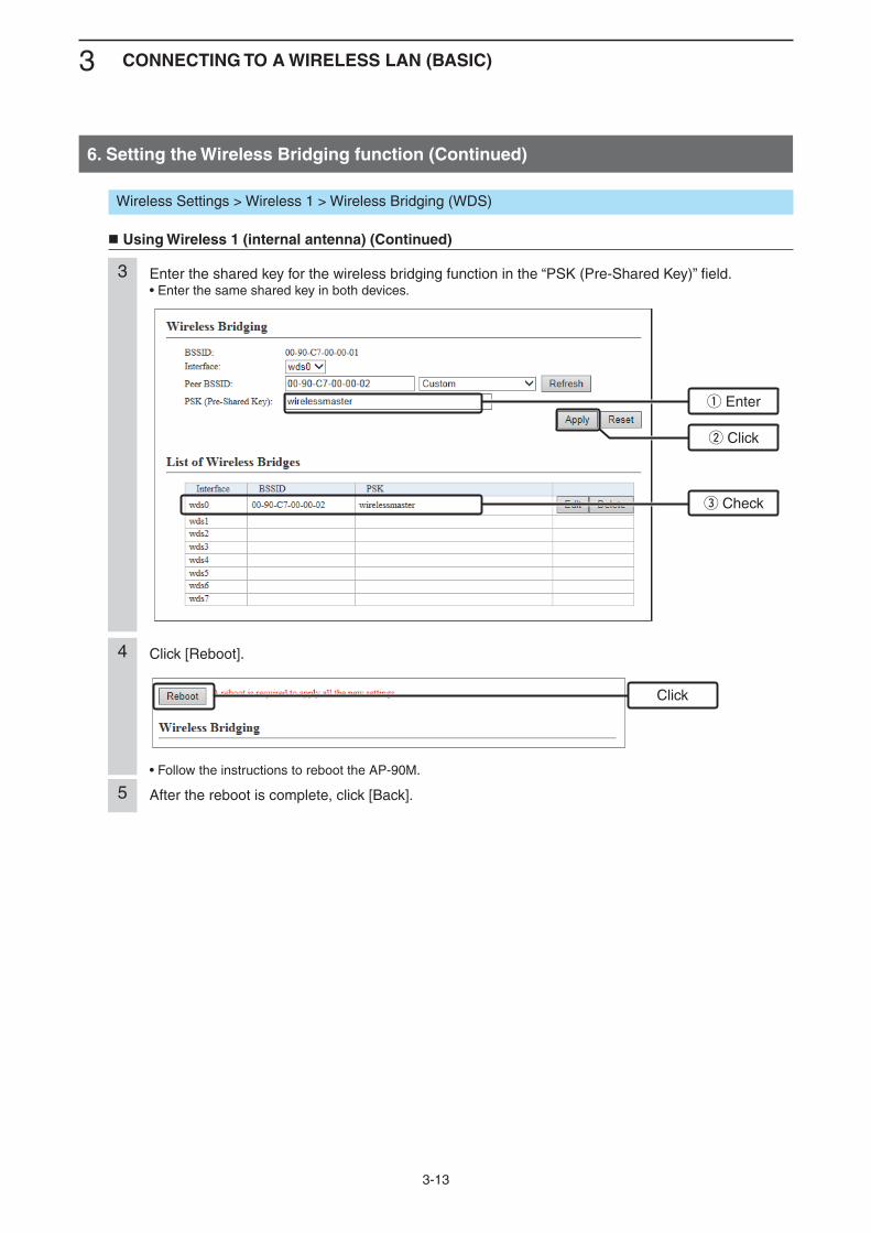
Enter the shared key for the wireless bridging function in the “PSK (Pre-Shared Key)” field.• Enter the same shared key in both devices.
3
q Enter
e Check
w Click
Wireless Settings > Wireless 1 > Wireless Bridging (WDS)
Using Wireless 1 (internal antenna) (Continued)
Click [Reboot].
• Follow the instructions to reboot the AP-90M.
4
After the reboot is complete, click [Back].5
Click
3 CONNECTING TO A WIRELESS LAN (BASIC)
3-14
Wireless Settings > Wireless 2 > Wireless Bridging (WBR)
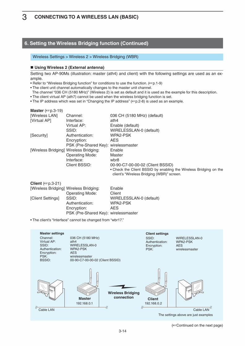
Using Wireless 2 (External antenna)Setting two AP-90Ms (illustration: master (ath4) and client) with the following settings are used as an ex-ample.• Refer to “Wireless Bridging function” for conditions to use the function. (+p.1-9)• The client unit channel automatically changes to the master unit channel. The channel “036 CH (5180 MHz)” (Wireless 2) is set as default and it is used as the example for this description.• The client virtual AP (ath7) cannot be used when the wireless bridging function is set.• The IP address which was set in “Changing the IP address” (+p.2-8) is used as an example.
Master (+p.3-19)[Wireless LAN] Channel: 036 CH (5180 MHz) (default)[Virtual AP] Interface: ath4 Virtual AP: Enable (default) SSID: WIRELESSLAN-0 (default)[Security] Authentication: WPA2-PSK Encryption: AES PSK (Pre-Shared Key): wirelessmaster[Wireless Bridging] Wireless Bridging: Enable Operating Mode: Master Interface: wbr8 Client BSSID: 00-90-C7-00-00-02 (Client BSSID) • Check the Client BSSID by enabling the Wireless Bridging on the
client’s “Wireless Bridging (WBR)” screen.
Client (+p.3-21)[Wireless Bridging] Wireless Bridging: Enable Operating Mode: Client[Client Settings] SSID: WIRELESSLAN-0 (default) Authentication: WPA2-PSK Encryption: AES PSK (Pre-Shared Key): wirelessmaster
• The client’s “Interface” cannot be changed from “wbr17.”
6. Setting the Wireless Bridging function (Continued)
Wireless Bridgingconnection
Cable LAN Cable LAN
The settings above are just examples.
Master settingsChannel: 036 CH (5180 MHz)Virtual AP: ath4 SSID: WIRELESSLAN-0Authentication: WPA2-PSKEncryption: AESPSK: wirelessmasterBSSID: 00-90-C7-00-00-02 (Client BSSID)
192.168.0.1 192.168.0.2
Client settingsSSID: WIRELESSLAN-0Authentication: WPA2-PSKEncryption: AESPSK: wirelessmaster
Master Client
(+Continued on the next page)
3 CONNECTING TO A WIRELESS LAN (BASIC)
3-15
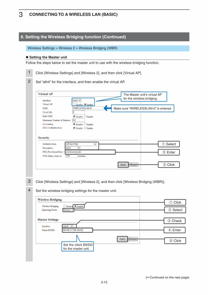
Click [Wireless Settings] and [Wireless 2], and then click [Virtual AP].1
Click [Wireless Settings] and [Wireless 2], and then click [Wireless Bridging (WBR)].3
Set “ath4” for the interface, and then enable the virtual AP.2
Set the wireless bridging settings for the master unit.4
Wireless Settings > Wireless 2 > Wireless Bridging (WBR)
Setting the Master unit
Follow the steps below to set the master unit to use with the wireless bridging function.
6. Setting the Wireless Bridging function (Continued)
(+Continued on the next page)
q Select
w Enter
r Enter
e Check
e Click
t Click
Make sure “WIRELESSLAN-0” is entered.
w Select
q Click
The Master unit's virtual AP for the wireless bridging.
Set the client BSSID for the master unit.
3 CONNECTING TO A WIRELESS LAN (BASIC)
3-16
Wireless Settings > Wireless 2 > Wireless Bridging (WBR)
Setting the Master unit (Continued)
6. Setting the Wireless Bridging function
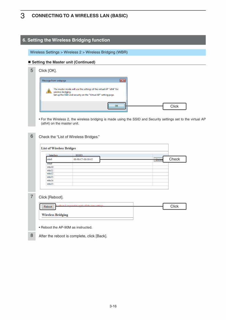
Click [OK].
• For the Wireless 2, the wireless bridging is made using the SSID and Security settings set to the virtual AP (ath4) on the master unit.
5
Check the “List of Wireless Bridges.”6
After the reboot is complete, click [Back].8
Click
Click
Check
7 Click [Reboot].
• Reboot the AP-90M as instructed.
3 CONNECTING TO A WIRELESS LAN (BASIC)
3-17
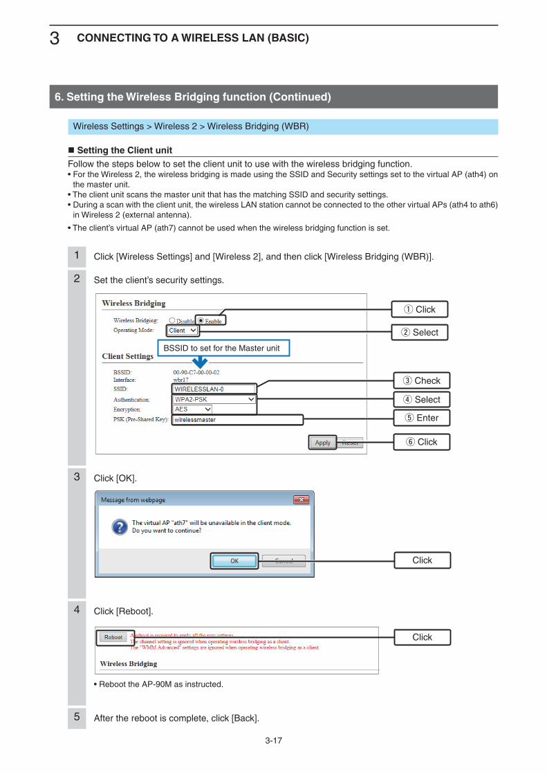
4 Click [Reboot].
• Reboot the AP-90M as instructed.
Click [OK].3
After the reboot is complete, click [Back].5
Click
Click
Click [Wireless Settings] and [Wireless 2], and then click [Wireless Bridging (WBR)].1
Set the client’s security settings.2
Wireless Settings > Wireless 2 > Wireless Bridging (WBR)
Setting the Client unitFollow the steps below to set the client unit to use with the wireless bridging function.• For the Wireless 2, the wireless bridging is made using the SSID and Security settings set to the virtual AP (ath4) on
the master unit.• The client unit scans the master unit that has the matching SSID and security settings.• During a scan with the client unit, the wireless LAN station cannot be connected to the other virtual APs (ath4 to ath6)
in Wireless 2 (external antenna).
• The client’s virtual AP (ath7) cannot be used when the wireless bridging function is set.
6. Setting the Wireless Bridging function (Continued)
y Click
w Select
q Click
BSSID to set for the Master unit
t Enter
r Select
e Check
3 CONNECTING TO A WIRELESS LAN (BASIC)
3-18
Wireless Settings > Wireless 1 > Wireless Bridging (WDS)
Wireless Settings > Wireless 2 > Wireless Bridging (WBR)
Management > Management Tools
Setting the wireless bridging function to the AP-90M for the RS-AP3 management
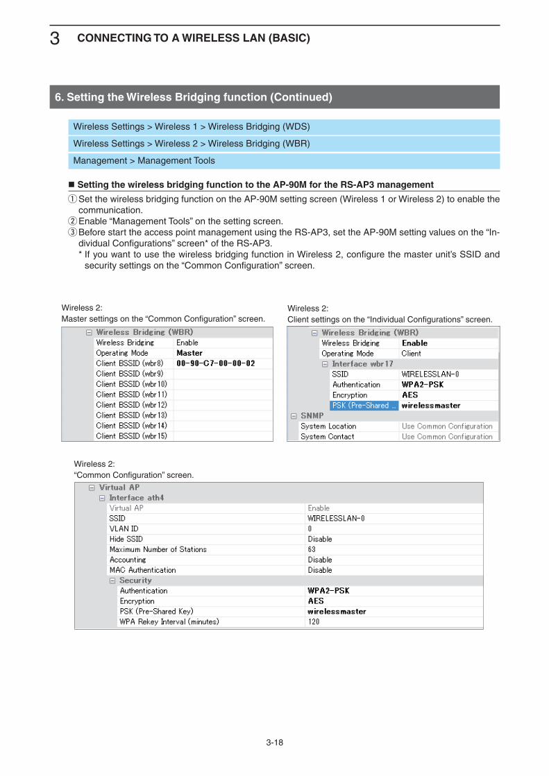
q Set the wireless bridging function on the AP-90M setting screen (Wireless 1 or Wireless 2) to enable the communication.
w Enable “Management Tools” on the setting screen.e Before start the access point management using the RS-AP3, set the AP-90M setting values on the “In-
dividual Configurations” screen* of the RS-AP3. * If you want to use the wireless bridging function in Wireless 2, configure the master unit’s SSID and
security settings on the “Common Configuration” screen.
6. Setting the Wireless Bridging function (Continued)
Wireless 2:Master settings on the “Common Configuration” screen.
Wireless 2:“Common Configuration” screen.
Wireless 2:Client settings on the “Individual Configurations” screen.
3 CONNECTING TO A WIRELESS LAN (BASIC)
3-19
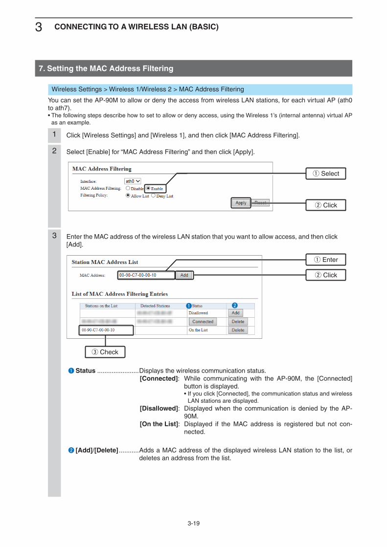
7. Setting the MAC Address Filtering
Click [Wireless Settings] and [Wireless 1], and then click [MAC Address Filtering].1
Select [Enable] for “MAC Address Filtering” and then click [Apply].2
Enter the MAC address of the wireless LAN station that you want to allow access, and then click [Add].
3
q Select
q Enter
w Click
w Click
e Check
Wireless Settings > Wireless 1/Wireless 2 > MAC Address Filtering
You can set the AP-90M to allow or deny the access from wireless LAN stations, for each virtual AP (ath0 to ath7).• The following steps describe how to set to allow or deny access, using the Wireless 1’s (internal antenna) virtual AP
as an example.
q Status .......................Displays the wireless communication status. [Connected]: While communicating with the AP-90M, the [Connected]
button is displayed. • If you click [Connected], the communication status and wireless
LAN stations are displayed. [Disallowed]: Displayed when the communication is denied by the AP-
90M. [On the List]: Displayed if the MAC address is registered but not con-
nected.
w [Add]/[Delete] ........... Adds a MAC address of the displayed wireless LAN station to the list, or deletes an address from the list.
Kq Kw

4-1
CONNECTING WIRELESS LAN(ADVANCED)
4
1. Automatically setting the channels.......................................................................................................... 4-2 Automatically setting the channels in the 2.4 GHz band.......................................................................... 4-2 Automatically setting the channels in the 5 GHz band............................................................................. 4-32. Setting the Accounting server ................................................................................................................. 4-4 Setting the Virtual APs individually .......................................................................................................... 4-4 Setting the Virtual APs together ............................................................................................................... 4-53. Setting the MAC Authentication Server (RADIUS) .................................................................................. 4-6 Setting the Virtual APs individually .......................................................................................................... 4-6 Setting the Virtual APs together ............................................................................................................... 4-74. Setting the RADIUS ................................................................................................................................... 4-8 Setting the Virtual APs individually .......................................................................................................... 4-8 Setting the Virtual APs together ............................................................................................................... 4-9
4 CONNECTING WIRELESS LAN (ADVANCED)
4-2
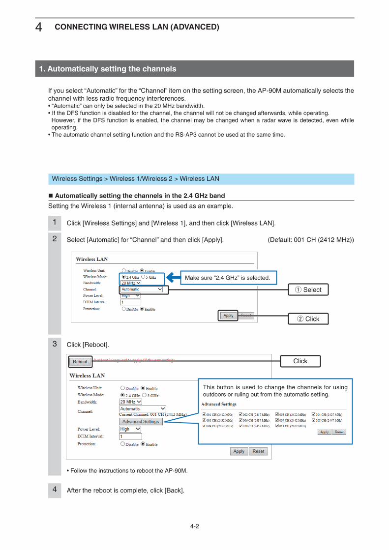
1. Automatically setting the channels
Select [Automatic] for “Channel” and then click [Apply]. (Default: 001 CH (2412 MHz))2
Click [Wireless Settings] and [Wireless 1], and then click [Wireless LAN].1
q Select
w Click
Wireless Settings > Wireless 1/Wireless 2 > Wireless LAN
Automatically setting the channels in the 2.4 GHz band
Setting the Wireless 1 (internal antenna) is used as an example.
If you select “Automatic” for the “Channel” item on the setting screen, the AP-90M automatically selects the channel with less radio frequency interferences.• “Automatic” can only be selected in the 20 MHz bandwidth.• If the DFS function is disabled for the channel, the channel will not be changed afterwards, while operating. However, if the DFS function is enabled, the channel may be changed when a radar wave is detected, even while operating.
• The automatic channel setting function and the RS-AP3 cannot be used at the same time.
Click [Reboot].
• Follow the instructions to reboot the AP-90M.
3
After the reboot is complete, click [Back].4
Click
This button is used to change the channels for using outdoors or ruling out from the automatic setting.
Make sure “2.4 GHz” is selected.
4 CONNECTING WIRELESS LAN (ADVANCED)
4-3
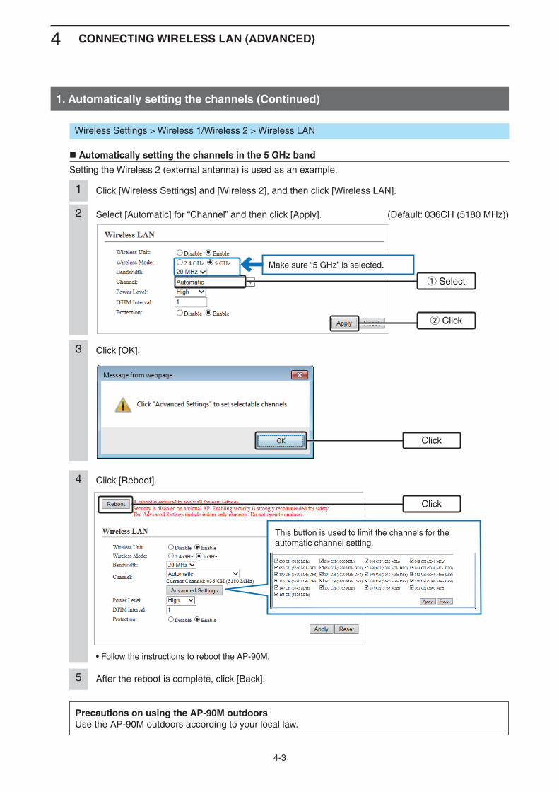
1. Automatically setting the channels (Continued)
Select [Automatic] for “Channel” and then click [Apply]. (Default: 036CH (5180 MHz))2
Click [OK].3
Click [Wireless Settings] and [Wireless 2], and then click [Wireless LAN].1
q Select
w Click
Click
Wireless Settings > Wireless 1/Wireless 2 > Wireless LAN
Automatically setting the channels in the 5 GHz band
Setting the Wireless 2 (external antenna) is used as an example.
Click [Reboot].
• Follow the instructions to reboot the AP-90M.
4
After the reboot is complete, click [Back].5
Click
Precautions on using the AP-90M outdoorsUse the AP-90M outdoors according to your local law.
Make sure “5 GHz” is selected.
This button is used to limit the channels for the automatic channel setting.
4 CONNECTING WIRELESS LAN (ADVANCED)
4-4
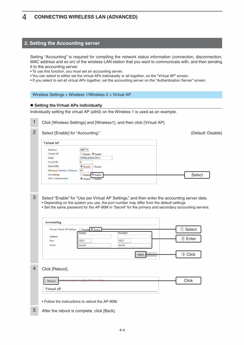
2. Setting the Accounting server
Select [Enable] for “Accounting.” (Default: Disable)2
Click [Wireless Settings] and [Wireless1], and then click [Virtual AP].1
Select
q Select
w Enter
e Click
Wireless Settings > Wireless 1/Wireless 2 > Virtual AP
Setting the Virtual APs individually
Individually setting the virtual AP (ath0) on the Wireless 1 is used as an example.
Setting “Accounting” is required for compiling the network status information (connection, disconnection, MAC address and so on) of the wireless LAN station that you want to communicate with, and then sending it to the accounting server.• To use this function, you must set an accounting server.• You can select to either set the virtual APs individually or all together, on the “Virtual AP” screen.• If you select to set all virtual APs together, set the accounting server on the “Authentication Server” screen.
3 Select “Enable” for “Use per Virtual AP Settings,” and then enter the accounting server data.• Depending on the system you use, the port number may differ from the default settings.• Set the same password for the AP-90M in “Secret” for the primary and secondary accounting servers.
Click [Reboot].
• Follow the instructions to reboot the AP-90M.
4
After the reboot is complete, click [Back].5
Click
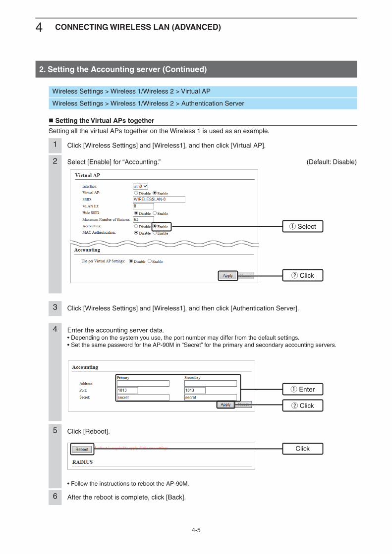
4 CONNECTING WIRELESS LAN (ADVANCED)
4-5
2. Setting the Accounting server (Continued)
Select [Enable] for “Accounting.” (Default: Disable)2
Click [Wireless Settings] and [Wireless1], and then click [Virtual AP].1
Click [Wireless Settings] and [Wireless1], and then click [Authentication Server].3
q Select
w Click
q Enter
w Click
Wireless Settings > Wireless 1/Wireless 2 > Virtual AP
Wireless Settings > Wireless 1/Wireless 2 > Authentication Server
Setting the Virtual APs together
Setting all the virtual APs together on the Wireless 1 is used as an example.
4 Enter the accounting server data.• Depending on the system you use, the port number may differ from the default settings.• Set the same password for the AP-90M in “Secret” for the primary and secondary accounting servers.
Click [Reboot].
• Follow the instructions to reboot the AP-90M.
5
After the reboot is complete, click [Back].6
Click
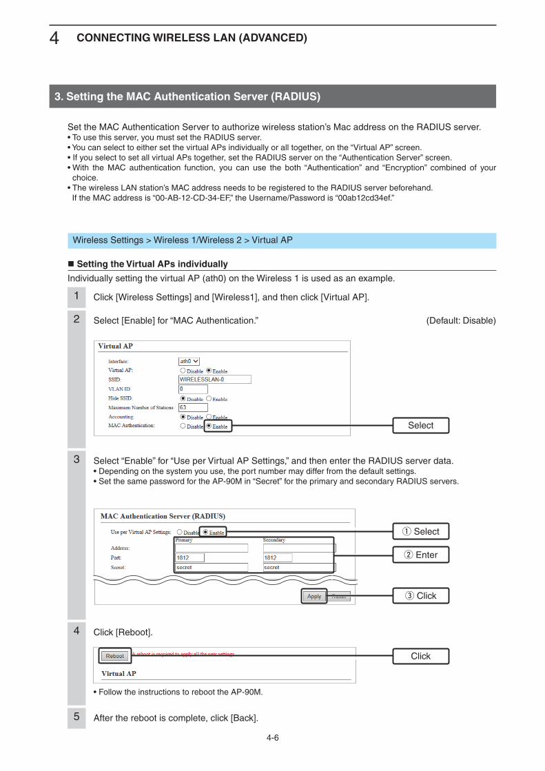
4 CONNECTING WIRELESS LAN (ADVANCED)
4-6
e Click
3. Setting the MAC Authentication Server (RADIUS)
Select [Enable] for “MAC Authentication.” (Default: Disable)2
Click [Wireless Settings] and [Wireless1], and then click [Virtual AP].1
Select
q Select
w Enter
Wireless Settings > Wireless 1/Wireless 2 > Virtual AP
Setting the Virtual APs individually
Individually setting the virtual AP (ath0) on the Wireless 1 is used as an example.
Set the MAC Authentication Server to authorize wireless station’s Mac address on the RADIUS server.• To use this server, you must set the RADIUS server.• You can select to either set the virtual APs individually or all together, on the “Virtual AP” screen.• If you select to set all virtual APs together, set the RADIUS server on the “Authentication Server” screen.• With the MAC authentication function, you can use the both “Authentication” and “Encryption” combined of your
choice.• The wireless LAN station’s MAC address needs to be registered to the RADIUS server beforehand. If the MAC address is “00-AB-12-CD-34-EF,” the Username/Password is “00ab12cd34ef.”
3 Select “Enable” for “Use per Virtual AP Settings,” and then enter the RADIUS server data.• Depending on the system you use, the port number may differ from the default settings.• Set the same password for the AP-90M in “Secret” for the primary and secondary RADIUS servers.
Click [Reboot].
• Follow the instructions to reboot the AP-90M.
4
After the reboot is complete, click [Back].5
Click
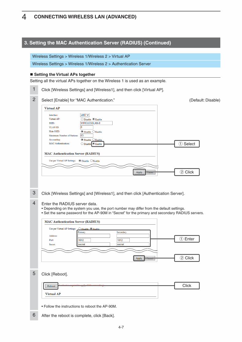
4 CONNECTING WIRELESS LAN (ADVANCED)
4-7
3. Setting the MAC Authentication Server (RADIUS) (Continued)
Select [Enable] for “MAC Authentication.” (Default: Disable)2
Click [Wireless Settings] and [Wireless1], and then click [Virtual AP].1
Click [Wireless Settings] and [Wireless1], and then click [Authentication Server].3
q Select
w Click
q Enter
w Click
Wireless Settings > Wireless 1/Wireless 2 > Virtual AP
Wireless Settings > Wireless 1/Wireless 2 > Authentication Server
Setting the Virtual APs together
Setting all the virtual APs together on the Wireless 1 is used as an example.
4 Enter the RADIUS server data.• Depending on the system you use, the port number may differ from the default settings.• Set the same password for the AP-90M in “Secret” for the primary and secondary RADIUS servers.
Click [Reboot].
• Follow the instructions to reboot the AP-90M.
5
After the reboot is complete, click [Back].6
Click
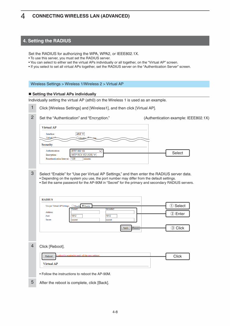
4 CONNECTING WIRELESS LAN (ADVANCED)
4-8
e Click
4. Setting the RADIUS
Set the “Authentication” and “Encryption.” (Authentication example: IEEE802.1X)2
Click [Wireless Settings] and [Wireless1], and then click [Virtual AP].1
Select
q Select
w Enter
Wireless Settings > Wireless 1/Wireless 2 > Virtual AP
Setting the Virtual APs individually
Individually setting the virtual AP (ath0) on the Wireless 1 is used as an example.
Set the RADIUS for authorizing the WPA, WPA2, or IEEE802.1X.• To use this server, you must set the RADIUS server.• You can select to either set the virtual APs individually or all together, on the “Virtual AP” screen.• If you select to set all virtual APs together, set the RADIUS server on the “Authentication Server” screen.
3 Select “Enable” for “Use per Virtual AP Settings,” and then enter the RADIUS server data.• Depending on the system you use, the port number may differ from the default settings.• Set the same password for the AP-90M in “Secret” for the primary and secondary RADIUS servers.
Click [Reboot].
• Follow the instructions to reboot the AP-90M.
4
After the reboot is complete, click [Back].5
Click
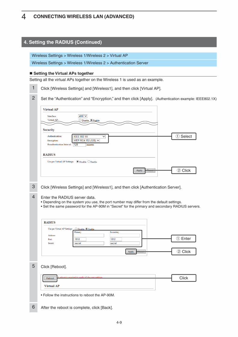
4 CONNECTING WIRELESS LAN (ADVANCED)
4-9
4. Setting the RADIUS (Continued)
Set the “Authentication” and “Encryption,” and then click [Apply]. (Authentication example: IEEE802.1X)2
Click [Wireless Settings] and [Wireless1], and then click [Virtual AP].1
Click [Wireless Settings] and [Wireless1], and then click [Authentication Server].3
q Select
w Click
q Enter
w Click
Wireless Settings > Wireless 1/Wireless 2 > Virtual AP
Wireless Settings > Wireless 1/Wireless 2 > Authentication Server
Setting the Virtual APs together
Setting all the virtual APs together on the Wireless 1 is used as an example.
4 Enter the RADIUS server data.• Depending on the system you use, the port number may differ from the default settings.• Set the same password for the AP-90M in “Secret” for the primary and secondary RADIUS servers.
Click [Reboot].
• Follow the instructions to reboot the AP-90M.
5
After the reboot is complete, click [Back].6
Click
5-1
OTHER FUNCTIONS 5
1. Controlling the setting screen access ................................................................................................... 5-22. Setting the internal clock ........................................................................................................................ 5-33. Using the DHCP Server ........................................................................................................................... 5-44. Using the Packet Filter ............................................................................................................................ 5-5 q Inhibiting the communication between wireless LAN stations in the Virtual AP .................................... 5-6 w Inhibiting the communication between Virtual APs ............................................................................... 5-7 e Limiting the AP-90M setting screen access to only the administrator’s PC .......................................... 5-8 r Enabling the internet access from a virtual AP and disabling the access to the local network ............. 5-95. Setting Web Authentication .................................................................................................................... 5-10 Setting the Web Authentication screens ................................................................................................ 5-10 Creating a custom page ......................................................................................................................... 5-116. Disabled HTTP/HTTPS ............................................................................................................................. 5-12 If you cannot access the setting screen ................................................................................................. 5-127. About the PIN code.................................................................................................................................. 5-13 Checking the PIN code .......................................................................................................................... 5-138. About SYSLOG ........................................................................................................................................ 5-14
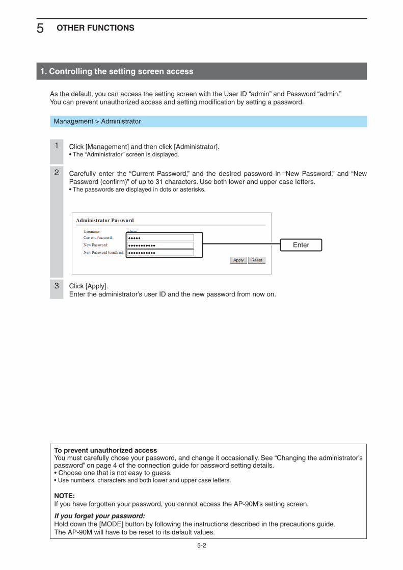
5 OTHER FUNCTIONS
5-2
1. Controlling the setting screen access
To prevent unauthorized accessYou must carefully chose your password, and change it occasionally. See “Changing the administrator’s password” on page 4 of the connection guide for password setting details.• Choose one that is not easy to guess.• Use numbers, characters and both lower and upper case letters.
NOTE: If you have forgotten your password, you cannot access the AP-90M’s setting screen.
If you forget your password:Hold down the [MODE] button by following the instructions described in the precautions guide.The AP-90M will have to be reset to its default values.
Click [Management] and then click [Administrator].• The “Administrator” screen is displayed.
1
Carefully enter the “Current Password,” and the desired password in “New Password,” and “New Password (confirm)” of up to 31 characters. Use both lower and upper case letters.• The passwords are displayed in dots or asterisks.
2
Click [Apply].Enter the administrator’s user ID and the new password from now on.
3
As the default, you can access the setting screen with the User ID “admin” and Password “admin.”You can prevent unauthorized access and setting modification by setting a password.
Management > Administrator
Enter
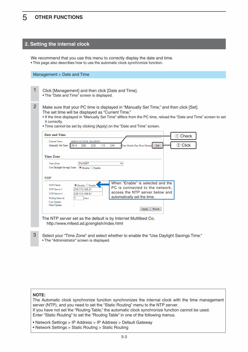
5 OTHER FUNCTIONS
5-3
We recommend that you use this menu to correctly display the date and time.• This page also describes how to use the automatic clock synchronize function.
Management > Date and Time
2. Setting the internal clock
NOTE:The Automatic clock synchronize function synchronizes the internal clock with the time management server (NTP), and you need to set the “Static Routing” menu to the NTP server.If you have not set the “Routing Table,” the automatic clock synchronize function cannot be used.Enter “Static Routing” to set the “Routing Table” in one of the following menus.
• Network Settings > IP Address > IP Address > Default Gateway• Network Settings > Static Routing > Static Routing
Click [Management] and then click [Date and Time].• The “Date and Time” screen is displayed.
1
Make sure that your PC time is displayed in “Manually Set Time,” and then click [Set].The set time will be displayed as “Current Time.”• If the time displayed in “Manually Set Time” differs from the PC time, reload the “Date and Time” screen to set
it correctly.• Time cannot be set by clicking [Apply] on the “Date and Time” screen.
2
The NTP server set as the default is by Internet Multifeed Co. http://www.mfeed.ad.jp/english/index.html
When “Enable” is selected and the PC is connected to the network, access the NTP server below and automatically set the time.
q Check
w Click
Select your “Time Zone” and select whether to enable the “Use Daylight Savings Time.”• The “Administrator” screen is displayed.
3
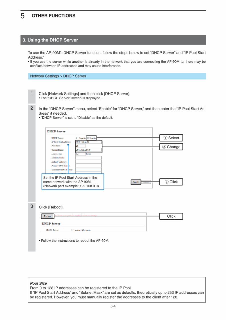
5 OTHER FUNCTIONS
5-4
3. Using the DHCP Server
Click [Network Settings] and then click [DHCP Server].• The “DHCP Server” screen is displayed.
1
In the “DHCP Server” menu, select “Enable” for “DHCP Server,” and then enter the “IP Pool Start Ad-dress” if needed.• “DHCP Server” is set to “Disable” as the default.
2
Click [Reboot].
• Follow the instructions to reboot the AP-90M.
3
Pool SizeFrom 0 to 128 IP addresses can be registered to the IP Pool.If “IP Pool Start Address” and “Subnet Mask” are set as defaults, theoretically up to 253 IP addresses can be registered. However, you must manually register the addresses to the client after 128.
Set the IP Pool Start Address in the same network with the AP-90M. (Network part example: 192.168.0.0)
To use the AP-90M’s DHCP Server function, follow the steps below to set “DHCP Server” and “IP Pool Start Address.”• If you use the server while another is already in the network that you are connecting the AP-90M to, there may be
conflicts between IP addresses and may cause interference.
Network Settings > DHCP Server
w Change
e Click
Click
q Select
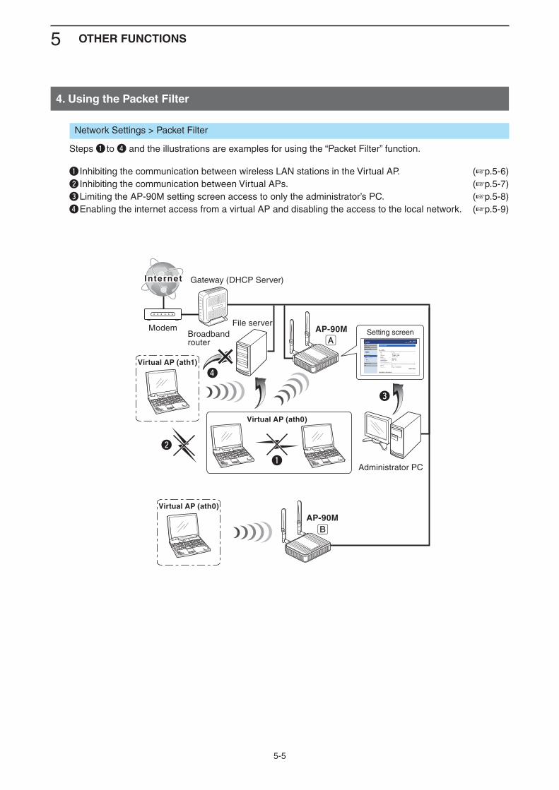
5 OTHER FUNCTIONS
5-5
4. Using the Packet Filter
Network Settings > Packet Filter
Steps q to r and the illustrations are examples for using the “Packet Filter” function.
q Inhibiting the communication between wireless LAN stations in the Virtual AP. (+p.5-6)w Inhibiting the communication between Virtual APs. (+p.5-7)e Limiting the AP-90M setting screen access to only the administrator’s PC. (+p.5-8)r Enabling the internet access from a virtual AP and disabling the access to the local network. (+p.5-9)
InternetInternet
ModemBroadbandrouter
AP-90MFile server
Administrator PC
Setting screen
e
Virtual AP (ath0)
q
w
rVirtual AP (ath1)
A
B
Virtual AP (ath0)
Gateway (DHCP Server)
AP-90M
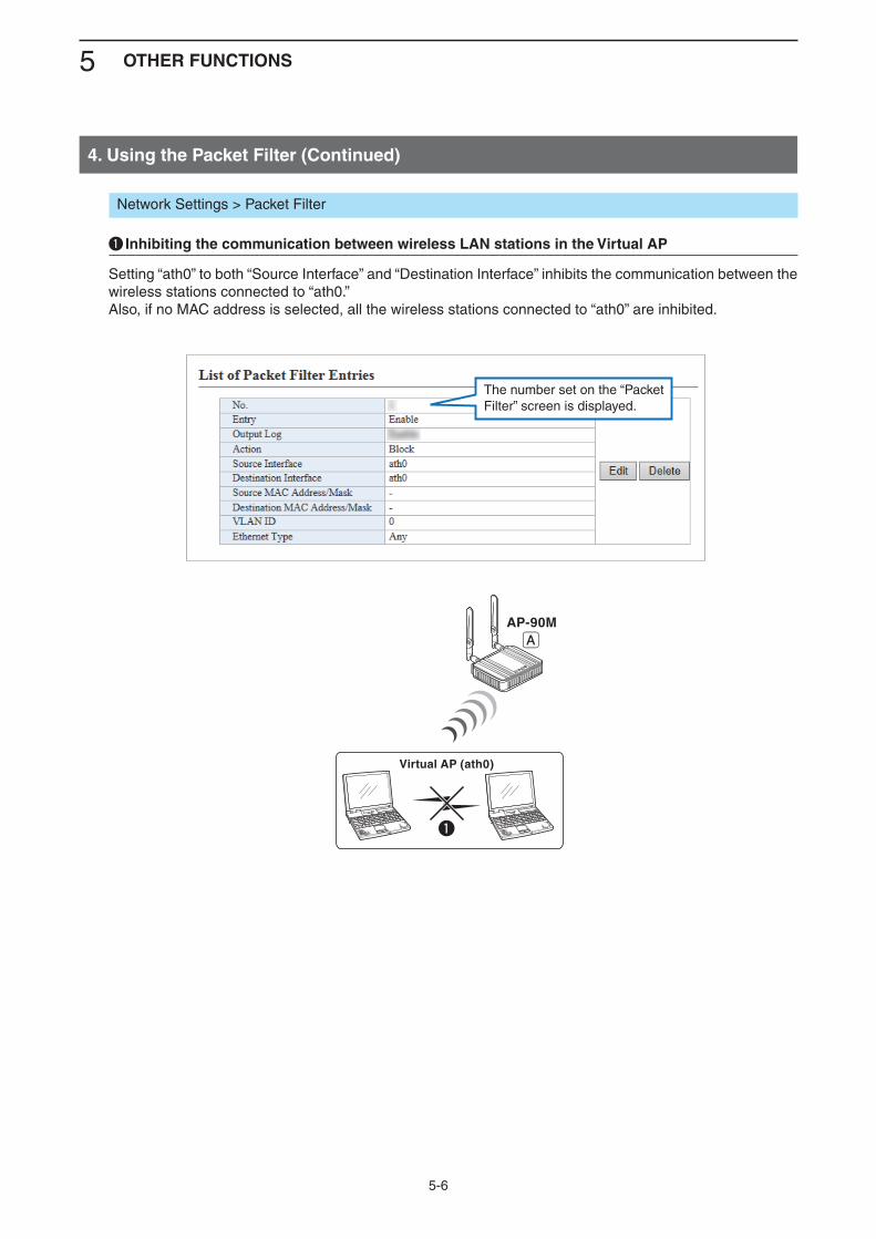
5 OTHER FUNCTIONS
5-6
4. Using the Packet Filter (Continued)
Network Settings > Packet Filter
q Inhibiting the communication between wireless LAN stations in the Virtual AP
Setting “ath0” to both “Source Interface” and “Destination Interface” inhibits the communication between the wireless stations connected to “ath0.”Also, if no MAC address is selected, all the wireless stations connected to “ath0” are inhibited.
AP-90M
Virtual AP (ath0)
q
A
The number set on the “Packet Filter” screen is displayed.
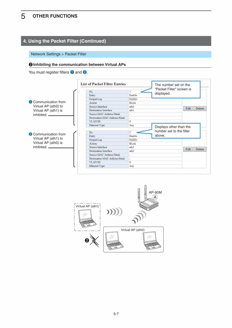
5 OTHER FUNCTIONS
5-7
4. Using the Packet Filter (Continued)
Network Settings > Packet Filter
w Inhibiting the communication between Virtual APs
You must register filters q and w.
AP-90M
Virtual AP (ath0)
w
Virtual AP (ath1)
A
q Communication from Virtual AP (ath0) to Virtual AP (ath1) is inhibited.
w Communication from Virtual AP (ath1) to Virtual AP (ath0) is inhibited.
The number set on the “Packet Filter” screen is displayed.
Displays other than the number set to the filter above.
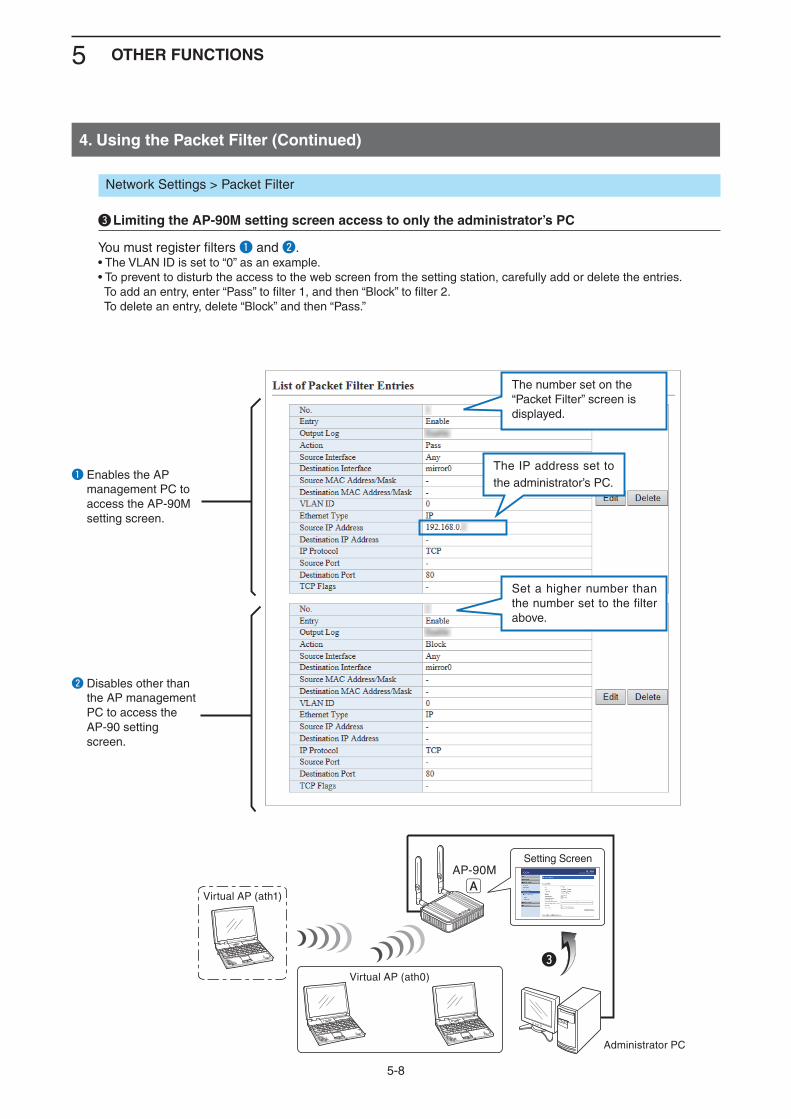
5 OTHER FUNCTIONS
5-8
4. Using the Packet Filter (Continued)
Network Settings > Packet Filter
e Limiting the AP-90M setting screen access to only the administrator’s PC
You must register filters q and w.• The VLAN ID is set to “0” as an example.• To prevent to disturb the access to the web screen from the setting station, carefully add or delete the entries. To add an entry, enter “Pass” to filter 1, and then “Block” to filter 2. To delete an entry, delete “Block” and then “Pass.”
AP-90M
Administrator PC
Setting Screen
eVirtual AP (ath0)
Virtual AP (ath1)A
q Enables the AP management PC to access the AP-90M setting screen.
The number set on the “Packet Filter” screen is displayed.
Set a higher number than the number set to the filter above.
The IP address set to the administrator’s PC.
w Disables other than the AP management PC to access the AP-90 setting screen.
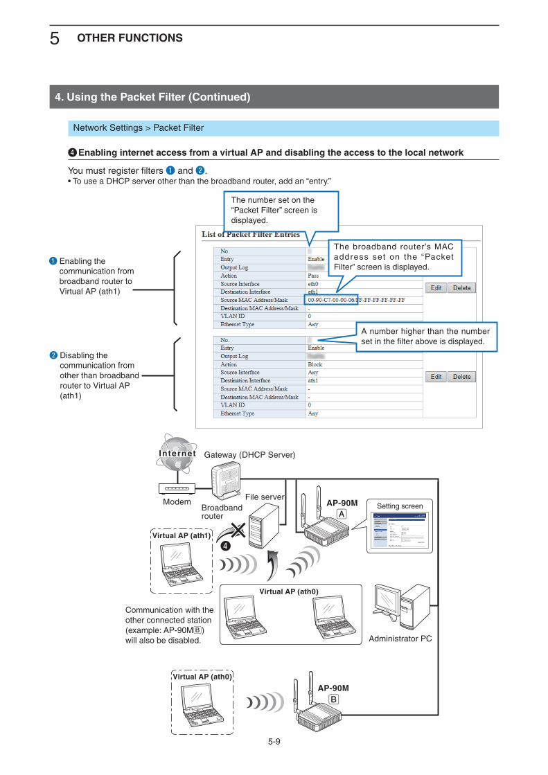
5 OTHER FUNCTIONS
5-9
4. Using the Packet Filter (Continued)
Network Settings > Packet Filter
r Enabling internet access from a virtual AP and disabling the access to the local network
You must register filters q and w.• To use a DHCP server other than the broadband router, add an “entry.”
InternetInternet
ModemBroadbandrouter
AP-90MFile server
Administrator PC
Setting screen
Virtual AP (ath0)
rVirtual AP (ath1)
A
B
Virtual AP (ath0)
Gateway (DHCP Server)
AP-90M
q Enabling the communication from broadband router to Virtual AP (ath1)
The number set on the “Packet Filter” screen is displayed.
The broadband router’s MAC address set on the “Packet Filter” screen is displayed.
A number higher than the number set in the filter above is displayed.
w Disabling the communication from other than broadband router to Virtual AP (ath1)
Communication with the other connected station (example: AP-90MB) will also be disabled.
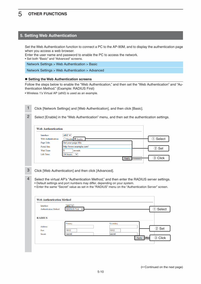
5 OTHER FUNCTIONS
5-10
5. Setting Web Authentication
Set the Web Authentication function to connect a PC to the AP-90M, and to display the authentication page when you access a web browser.Enter the user name and password to enable the PC to access the network.• Set both “Basic” and “Advanced” screens.
Network Settings > Web Authentication > Basic
Network Settings > Web Authentication > Advanced
Setting the Web Authentication screens
Follow the steps below to enable the “Web Authentication,” and then set the “Web Authentication” and “Au-thentication Method.” (Example: RADIUS First)• Wireless 1’s Virtual AP (ath0) is used as an example.
Select [Enable] in the “Web Authentication” menu, and then set the authentication settings.2
Select the virtual AP’s “Authentication Method,” and then enter the RADIUS server settings.• Default settings and port numbers may differ, depending on your system.• Enter the same “Secret” value as set in the “RADIUS” menu on the “Authentication Server” screen.
4
Click [Network Settings] and [Web Authentication], and then click [Basic].1
Click [Web Authentication] and then click [Advanced].3
q Select
q Select
w Set
w Set
e Click
e Click
(+Continued on the next page)
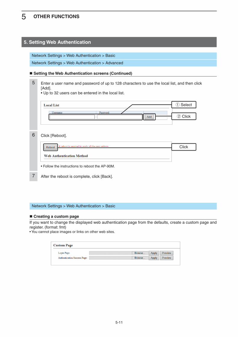
5 OTHER FUNCTIONS
5-11
5. Setting Web Authentication
Network Settings > Web Authentication > Basic
Creating a custom pageIf you want to change the displayed web authentication page from the defaults, create a custom page and register. (format: fmt)• You cannot place images or links on other web sites.
Network Settings > Web Authentication > Basic
Network Settings > Web Authentication > Advanced
Setting the Web Authentication screens (Continued)
Enter a user name and password of up to 128 characters to use the local list, and then click [Add].• Up to 32 users can be entered in the local list.
5
q Select
Click [Reboot].
• Follow the instructions to reboot the AP-90M.
6
After the reboot is complete, click [Back].7
Click
w Click
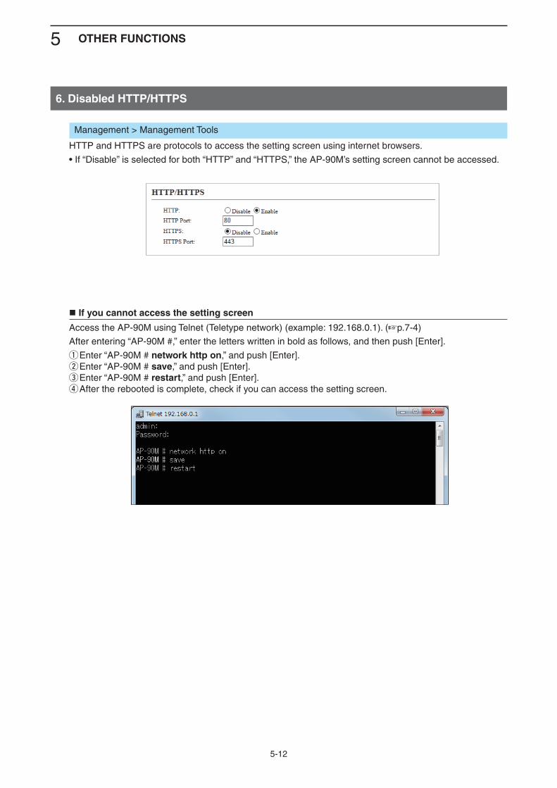
5 OTHER FUNCTIONS
5-12
6. Disabled HTTP/HTTPS
Management > Management Tools
HTTP and HTTPS are protocols to access the setting screen using internet browsers.
• If “Disable” is selected for both “HTTP” and “HTTPS,” the AP-90M’s setting screen cannot be accessed.
If you cannot access the setting screen
Access the AP-90M using Telnet (Teletype network) (example: 192.168.0.1). (+p.7-4)
After entering “AP-90M #,” enter the letters written in bold as follows, and then push [Enter].
q Enter “AP-90M # network http on,” and push [Enter].w Enter “AP-90M # save,” and push [Enter].e Enter “AP-90M # restart,” and push [Enter].r After the rebooted is complete, check if you can access the setting screen.
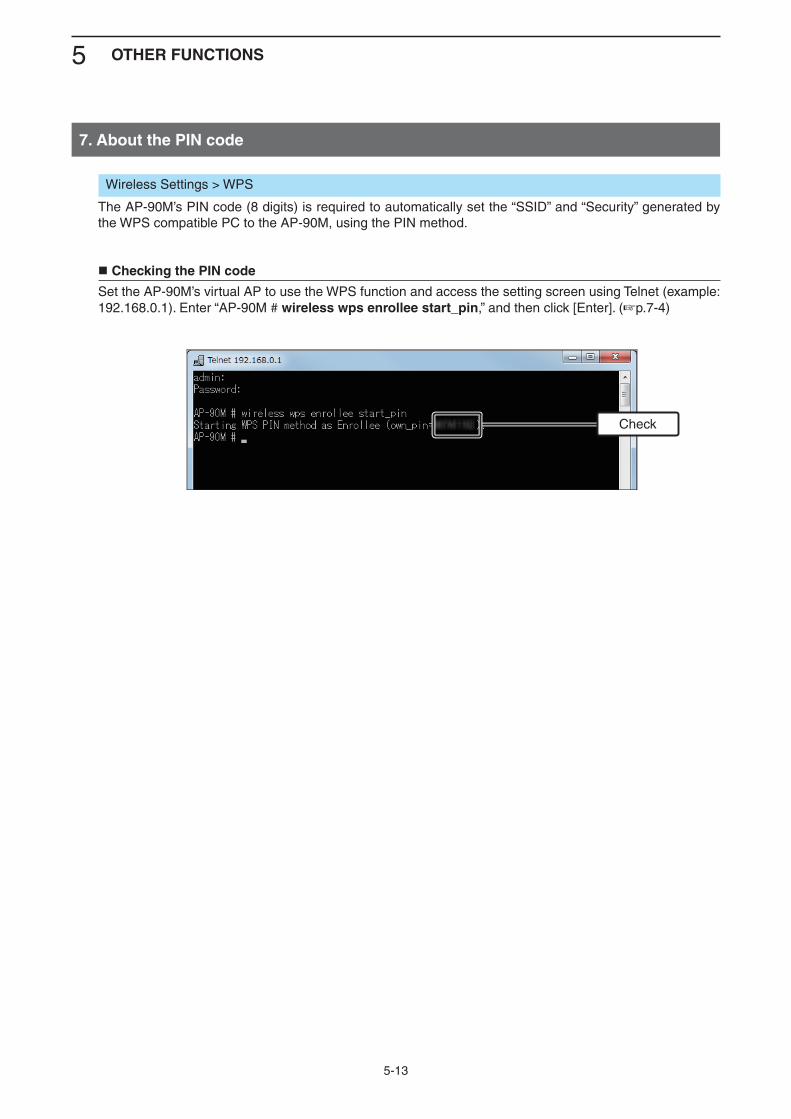
5 OTHER FUNCTIONS
5-13
7. About the PIN code
Wireless Settings > WPS
The AP-90M’s PIN code (8 digits) is required to automatically set the “SSID” and “Security” generated by the WPS compatible PC to the AP-90M, using the PIN method.
Checking the PIN code
Set the AP-90M’s virtual AP to use the WPS function and access the setting screen using Telnet (example: 192.168.0.1). Enter “AP-90M # wireless wps enrollee start_pin,” and then click [Enter]. (+p.7-4)
Check
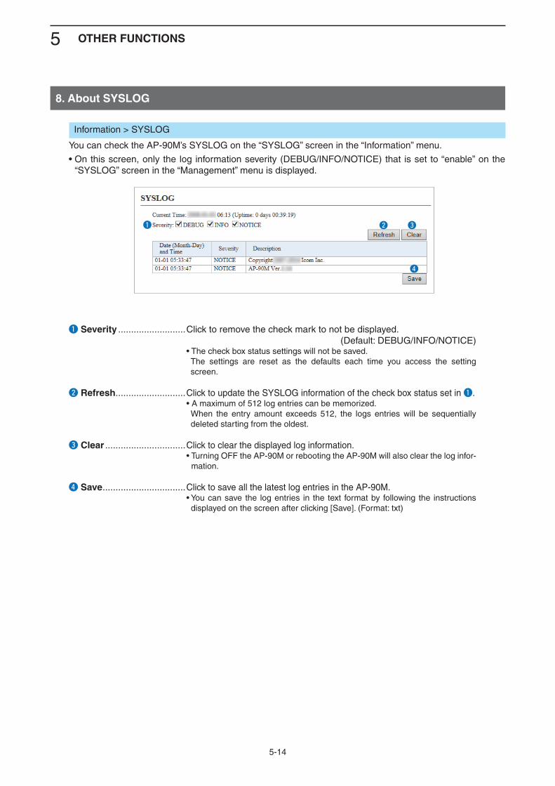
5 OTHER FUNCTIONS
5-14
8. About SYSLOG
Information > SYSLOG
You can check the AP-90M’s SYSLOG on the “SYSLOG” screen in the “Information” menu.
• On this screen, only the log information severity (DEBUG/INFO/NOTICE) that is set to “enable” on the “SYSLOG” screen in the “Management” menu is displayed.
q Severity ..........................Click to remove the check mark to not be displayed. (Default: DEBUG/INFO/NOTICE) • The check box status settings will not be saved. The settings are reset as the defaults each time you access the setting
screen.
w Refresh ...........................Click to update the SYSLOG information of the check box status set in q. • A maximum of 512 log entries can be memorized. When the entry amount exceeds 512, the logs entries will be sequentially
deleted starting from the oldest.
e Clear ...............................Click to clear the displayed log information. • Turning OFF the AP-90M or rebooting the AP-90M will also clear the log infor-
mation.
r Save ................................Click to save all the latest log entries in the AP-90M. • You can save the log entries in the text format by following the instructions
displayed on the screen after clicking [Save]. (Format: txt)
Kw Ke
Kr
Kq
6-1
MAINTENANCE 6
1. Checking and saving the settings .......................................................................................................... 6-22. Uploading the saved settings ................................................................................................................. 6-33. Restoring the factory defaults ................................................................................................................ 6-4 A Pushing [MODE] ................................................................................................................................... 6-4 B Using the setting screen ....................................................................................................................... 6-54. Firmware Update ..................................................................................................................................... 6-6 About the firmware ................................................................................................................................. 6-6 Firmware update note ............................................................................................................................ 6-6 A Manually updating the firmware ............................................................................................................ 6-7 B Firmware update online ........................................................................................................................ 6-85. Automatic setting using a USB flash drive ........................................................................................... 6-9 USB flash drive note .............................................................................................................................. 6-10 Supported USB flash drive specification ............................................................................................... 6-10 Naming the automatic setting files ......................................................................................................... 6-11 Automatic setting backups ..................................................................................................................... 6-11 Managing multiple setting files on one USB flash drive ......................................................................... 6-126. Automatically restoring from a USB flash drive ................................................................................... 6-13 Saving and restoring the setting file ....................................................................................................... 6-137. Firmware update using a USB flash drive ............................................................................................. 6-16 Updating the firmware ............................................................................................................................ 6-168. Setting the USB Authentication Key ...................................................................................................... 6-18 Entering the USB authentication key ..................................................................................................... 6-18
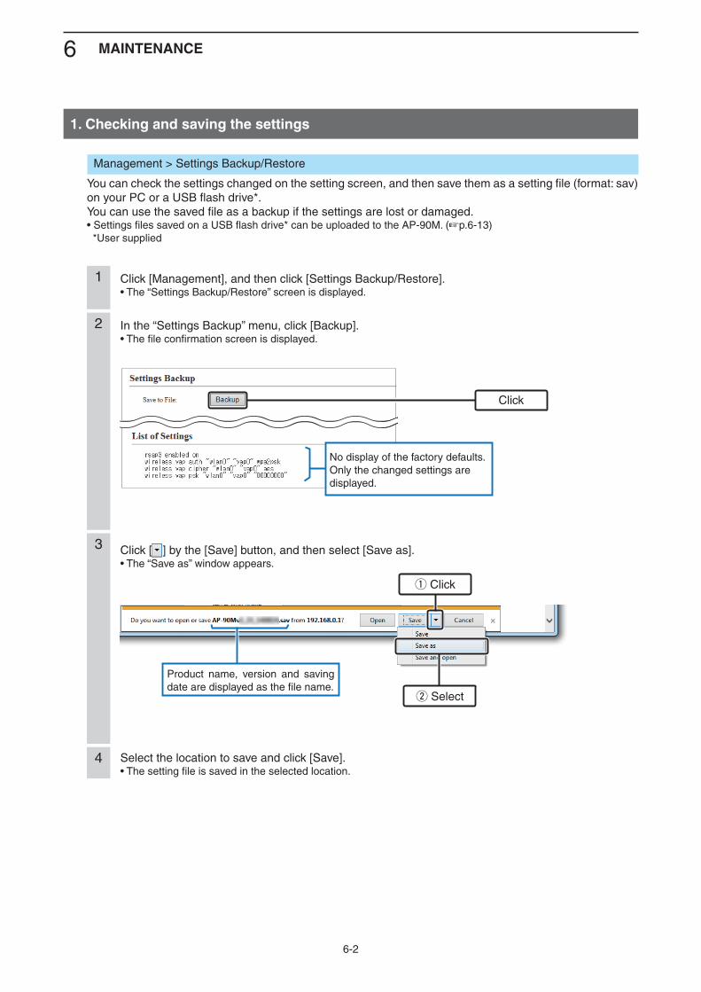
6 MAINTENANCE
6-2
1. Checking and saving the settings
Click [Management], and then click [Settings Backup/Restore].• The “Settings Backup/Restore” screen is displayed.
1
In the “Settings Backup” menu, click [Backup].• The file confirmation screen is displayed.
2
Click [ ] by the [Save] button, and then select [Save as].• The “Save as” window appears.
3
Select the location to save and click [Save].• The setting file is saved in the selected location.
4
No display of the factory defaults.Only the changed settings are displayed.
Product name, version and saving date are displayed as the file name.
Management > Settings Backup/Restore
You can check the settings changed on the setting screen, and then save them as a setting file (format: sav) on your PC or a USB flash drive*.You can use the saved file as a backup if the settings are lost or damaged.• Settings files saved on a USB flash drive* can be uploaded to the AP-90M. (+p.6-13) *User supplied
q Click
Click
w Select
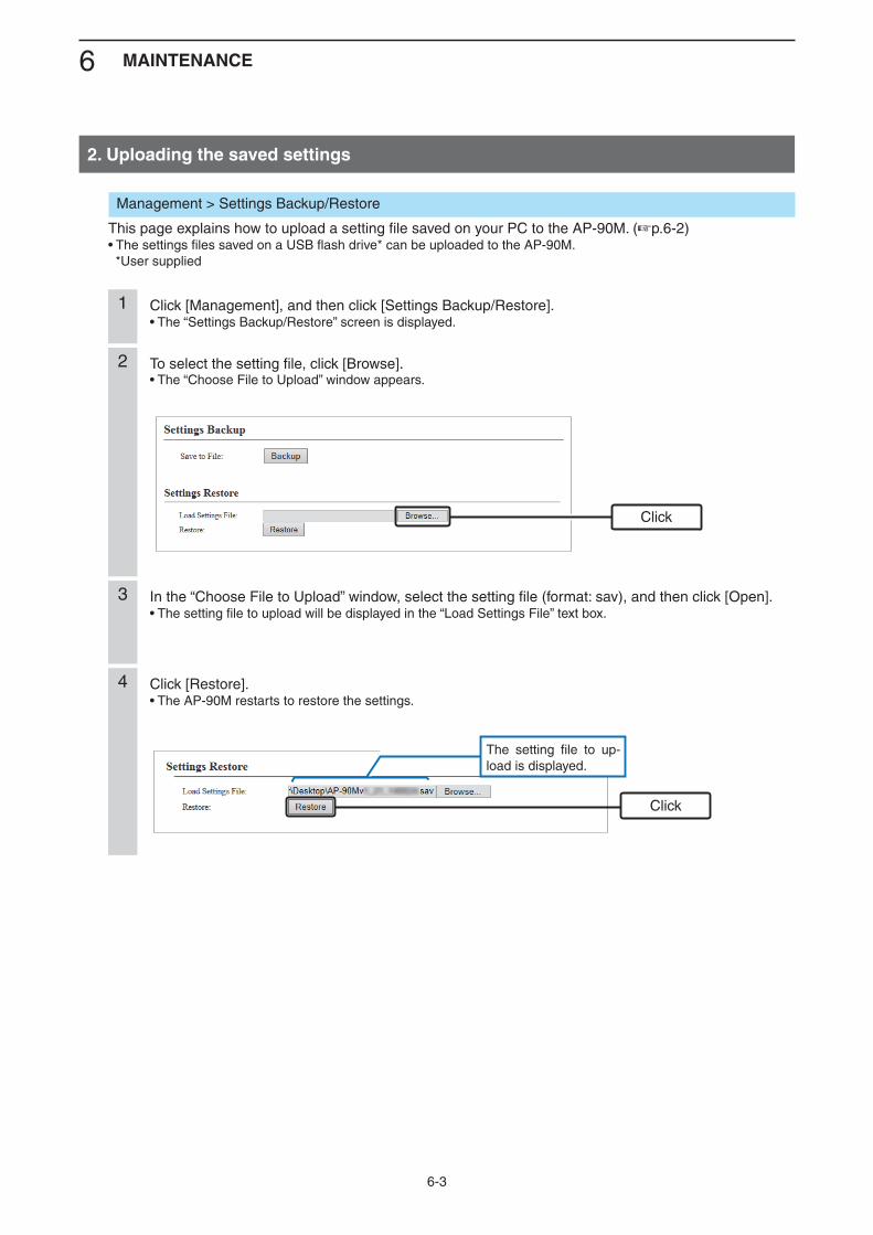
6 MAINTENANCE
6-3
Management > Settings Backup/Restore
This page explains how to upload a setting file saved on your PC to the AP-90M. (+p.6-2)• The settings files saved on a USB flash drive* can be uploaded to the AP-90M. *User supplied
Click [Management], and then click [Settings Backup/Restore].• The “Settings Backup/Restore” screen is displayed.
1
To select the setting file, click [Browse].• The “Choose File to Upload” window appears.
2
In the “Choose File to Upload” window, select the setting file (format: sav), and then click [Open].• The setting file to upload will be displayed in the “Load Settings File” text box.
3
Click [Restore].• The AP-90M restarts to restore the settings.
4
The setting file to up-load is displayed.
Click
Click
2. Uploading the saved settings
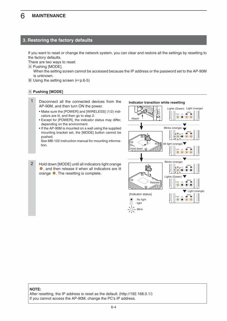
6 MAINTENANCE
6-4
If you want to reset or change the network system, you can clear and restore all the settings by resetting to the factory defaults.There are two ways to reset:A Pushing [MODE]. When the setting screen cannot be accessed because the IP address or the password set to the AP-90M
is unknown.B Using the setting screen (+p.6-5)
A Pushing [MODE]
Disconnect all the connected devices from the AP-90M, and then turn ON the power.• Make sure the [POWER] and [WIRELESS] (1/2) indi-
cators are lit, and then go to step 2.• Except for [POWER], the indicator status may differ,
depending on the environment.• If the AP-90M is mounted on a wall using the supplied
mounting bracket set, the [MODE] button cannot be pushed.
See MB-102 instruction manual for mounting informa-tion.
1
Hold down [MODE] until all indicators light orange , and then release it when all indicators are lit
orange . The resetting is complete.
2
Attach
Release
Hold down
Light (orange)Lights (Green)
Blinks (orange)
All light (orange)
Blinks (orange)
Lights (Green)
Light (orange)
AP-90M
WIRELESS ACCESS POINT
: No light
[Indicator status]
Indicator transition while resetting
: light
: Blink
NOTE:After resetting, the IP address is reset as the default. (http://192.168.0.1/)If you cannot access the AP-90M, change the PC’s IP address.
3. Restoring the factory defaults

6 MAINTENANCE
6-5
Management > Factory Defaults
If you can access the setting screen with the IP address and the administrator’s password, you can restore all the default settings from the setting screen.If the IP address and the password are unknown, see page 6-4.
B Using the setting screen
Click [Management], and then click [Factory Defaults].• The “Factory Defaults” screen is displayed.
1
Select the restore button, and then click [Restore]. (Default: Restore All Settings)2
Click [OK].• The AP-90M restarts to restore the default settings.
3
After the restart is complete, click [Back].4
Click
q Select
w Click
NOTE about “Factory Defaults”:Restore All Settings ➥
Restores all the set values to their defaults, including the IP address. (http://192.168.0.1/) If you cannot access the AP-90M, change the PC’s IP address.
Restore Wireless Settings ➥ Restores only the settings set on the “Wireless Settings” screen to their default values. After the restoring is complete, “SSID” is set to “WIRELESSLAN-0,” and “Encryption” is set to “None.” If the SSID or encryption set by restoring the factory defaults differ from those set in the AP-90M, you
will not be able to access the setting screen. In such a case, change the settings in the “Wireless Set-tings” menu and the wireless LAN station settings.
3. Restoring the factory defaults (Continued)
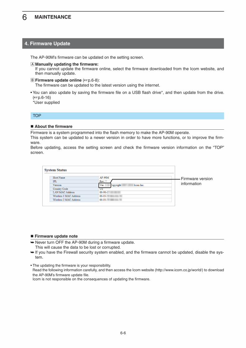
6 MAINTENANCE
6-6
Firmware version information
The AP-90M’s firmware can be updated on the setting screen.
A Manually updating the firmware: If you cannot update the firmware online, select the firmware downloaded from the Icom website, and
then manually update.
B Firmware update online (+p.6-8): The firmware can be updated to the latest version using the internet.
• You can also update by saving the firmware file on a USB flash drive*, and then update from the drive. (+p.6-16)
*User supplied
TOP
About the firmwareFirmware is a system programmed into the flash memory to make the AP-90M operate.This system can be updated to a newer version in order to have more functions, or to improve the firm-ware.Before updating, access the setting screen and check the firmware version information on the “TOP” screen.
Firmware update noteNever turn OFF the AP-90M during a firmware update. ➥
This will cause the data to be lost or corrupted. If you have the Firewall security system enabled, and the firmware cannot be updated, disable the sys- ➥tem.
• The updating the firmware is your responsibility. Read the following information carefully, and then access the Icom website (http://www.icom.co.jp/world/) to download the AP-90M’s firmware update file.
Icom is not responsible on the consequences of updating the firmware.
4. Firmware Update
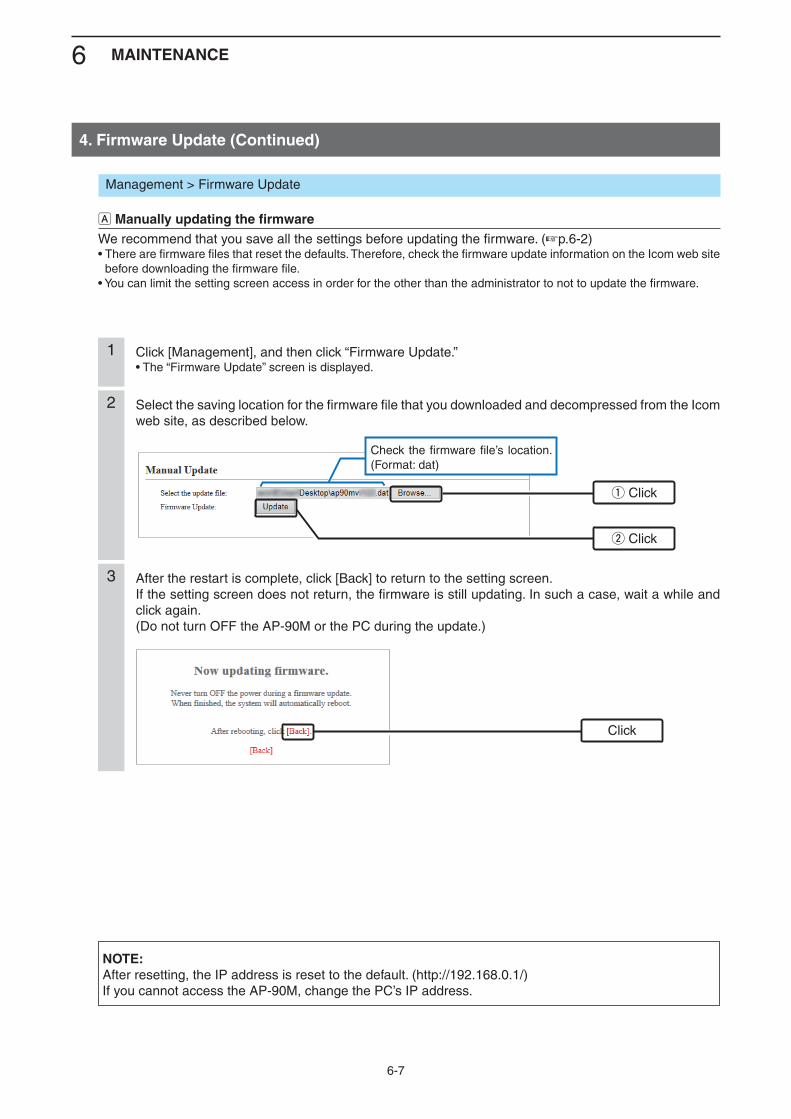
6 MAINTENANCE
6-7
Click [Management], and then click “Firmware Update.”• The “Firmware Update” screen is displayed.
1
Select the saving location for the firmware file that you downloaded and decompressed from the Icom web site, as described below.
2
After the restart is complete, click [Back] to return to the setting screen.If the setting screen does not return, the firmware is still updating. In such a case, wait a while and click again.(Do not turn OFF the AP-90M or the PC during the update.)
3
Check the firmware file’s location. (Format: dat)
Management > Firmware Update
A Manually updating the firmwareWe recommend that you save all the settings before updating the firmware. (+p.6-2)• There are firmware files that reset the defaults. Therefore, check the firmware update information on the Icom web site
before downloading the firmware file.• You can limit the setting screen access in order for the other than the administrator to not to update the firmware.
Click
q Click
w Click
NOTE:After resetting, the IP address is reset to the default. (http://192.168.0.1/)If you cannot access the AP-90M, change the PC’s IP address.
4. Firmware Update (Continued)
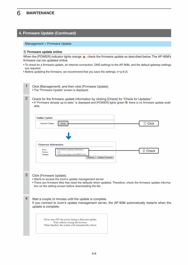
6 MAINTENANCE
6-8
Management > Firmware Update
B Firmware update onlineWhen the [POWER] indicator lights orange , check the firmware update as described below. The AP-90M’s firmware can be updated online.• To check for a firmware update, an internet connection, DNS settings to the AP-90M, and the default gateway settings
are required.• Before updating the firmware, we recommend that you save the settings. (+p.6-2)
Click [Management], and then click [Firmware Update].• The “Firmware Update” screen is displayed.
1
Check for the firmware update information by clicking [Check] for “Check for Updates.”• If “Firmware already up-to-date.” is displayed and [POWER] lights green , there is no firmware update avail-
able.
2
Click [Firmware Update].• Starts to access the Icom’s update management server.• There are firmware files that reset the defaults when updated. Therefore, check the firmware update informa-
tion on the setting screen before downloading the file.
3
Wait a couple of minutes until the update is complete.If you connect to Icom’s update management server, the AP-90M automatically restarts when the update is complete.
4
w Check
q Click
4. Firmware Update (Continued)
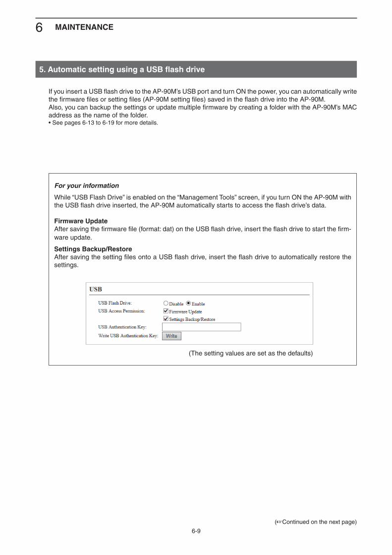
6 MAINTENANCE
6-9
(+Continued on the next page)
If you insert a USB flash drive to the AP-90M’s USB port and turn ON the power, you can automatically write the firmware files or setting files (AP-90M setting files) saved in the flash drive into the AP-90M.Also, you can backup the settings or update multiple firmware by creating a folder with the AP-90M’s MAC address as the name of the folder.• See pages 6-13 to 6-19 for more details.
5. Automatic setting using a USB flash drive
For your information
While “USB Flash Drive” is enabled on the “Management Tools” screen, if you turn ON the AP-90M with the USB flash drive inserted, the AP-90M automatically starts to access the flash drive’s data.
Firmware UpdateAfter saving the firmware file (format: dat) on the USB flash drive, insert the flash drive to start the firm-ware update.
Settings Backup/RestoreAfter saving the setting files onto a USB flash drive, insert the flash drive to automatically restore the settings.
(The setting values are set as the defaults)

6 MAINTENANCE
6-10
USB flash drive note• A USB flash drive such as one with biometric authentication, or one with password protection is not sup-
ported.• Before using a USB flash drive, backup the flash drive’s data.• Turn OFF the AP-90M’s power before inserting or removing the USB flash drive, to prevent data loss or
corruption. NEVER remove the flash drive while transferring data (the [POWER] indicator lights orange ). This may cause data loss or corruption, or may damage the USB flash drive.
• Securely insert the USB flash drive.• The [POWER] indicator lights orange while accessing the flash drive data. The [POWER] indicator lights green when the “Settings Backup/Restore” operation is complete. All indicators light orange while updating the firmware.• When “USB Authentication Key” is set (+p.6-19), if the flash drive’s key does not match the set authentication
key, the automatic setting function cannot be used.• When restoring setting data, the original setting data is automatically saved as “bakdata.sav” on the USB
flash drive, as a backup.• If the setting file or the firmware file saved in the flash drive is the same as the ones in the AP-90M, is
damaged, or the flash drive is for other than the AP-90M, the automatic setting or firmware update cannot be used.
If the version does not match the AP-90M, the automatic setting function starts.• If both the setting file and the firmware file are saved on the flash drive, the automatic setting starts by
restoring, and then updating the firmware.
Supported USB flash drive specification
Interface: USB 2.0/1.1Device: USB flash drive (USB Mass Storage Class)Format: FAT16/FAT32 (exFAT and NTFS are not supported)
5. Automatic setting using a USB flash drive (Continued)
(+Continued on the next page)
6 MAINTENANCE
6-11
Naming the automatic setting files
Name the setting file “savedata” (format: sav) on the USB flash drive.• You can only use the setting file saved in the “Save to File” setting on the “Setting Backup/Restore” screen in the “Management” menu. (+p.6-2)
Name the firmware file “firmware” (format: dat) on the USB flash drive.• Download the firmware file to use for the automatic firmware update from the Icom website and decom-
press the file. Then name the file “firmware.”
Automatic setting backups A total of 10 latest setting data files can be automatically backed up in the following naming manner.
The latest setting backup data file is automatically named “bakdata.sav.”
Example: The second latest is named “bakdata_1.sav.” The third latest is named “bakdata_2.sav.”
• If the number of backups exceeds 10, the oldest setting backup file (bakdata_10.sav) is deleted, and each number shifts to one higher number. (Example: “bakdata_9.sav” shifts to “bakdata_10.sav”)
• Firmware files are not backed up.• The setting file (bakdata.sav) is automatically backed up when you change a setting in the AP-90M.
5. Automatic setting using a USB flash drive (Continued)
(+Continued on the next page)
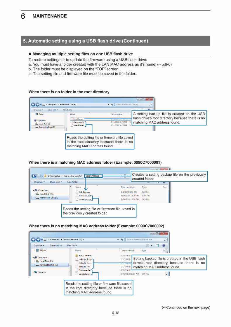
6 MAINTENANCE
6-12
(+Continued on the next page)
Managing multiple setting files on one USB flash drive To restore settings or to update the firmware using a USB flash drive:a. You must have a folder created with the LAN MAC address as it’s name. (+p.6-6) b. The folder must be displayed on the “TOP” screen.c. The setting file and firmware file must be saved in the folder..
5. Automatic setting using a USB flash drive (Continued)
When there is no folder in the root directory
When there is a matching MAC address folder (Example: 0090C7000001)
When there is no matching MAC address folder (Example: 0090C7000002)
Reads the setting file or firmware file saved in the root directory because there is no matching MAC address found.
Reads the setting file or firmware file saved in the root directory because there is no matching MAC address found.
Reads the setting file or firmware file saved in the previously created folder.
A setting backup file is created on the USB flash drive’s root directory because there is no matching MAC address found.
Setting backup file is created in the USB flash drive’s root directory because there is no matching MAC address found.
Creates a setting backup file on the previously created folder.
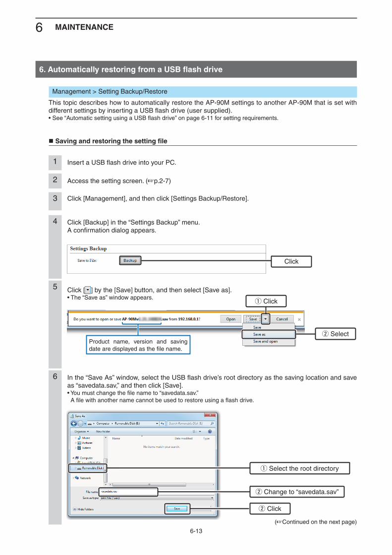
6 MAINTENANCE
6-13
Management > Setting Backup/Restore
This topic describes how to automatically restore the AP-90M settings to another AP-90M that is set with different settings by inserting a USB flash drive (user supplied).• See “Automatic setting using a USB flash drive” on page 6-11 for setting requirements.
Saving and restoring the setting file
Click [ ] by the [Save] button, and then select [Save as].• The “Save as” window appears.
5
Product name, version and saving date are displayed as the file name.
(+Continued on the next page)
Insert a USB flash drive into your PC.1
Access the setting screen. (+p.2-7)2
Click [Management], and then click [Settings Backup/Restore]. 3
Click [Backup] in the “Settings Backup” menu.A confirmation dialog appears.
4
In the “Save As” window, select the USB flash drive’s root directory as the saving location and save as “savedata.sav,” and then click [Save].• You must change the file name to “savedata.sav.” A file with another name cannot be used to restore using a flash drive.
6
Click
q Click
w Select
q Select the root directory
w Change to “savedata.sav”
w Click
6. Automatically restoring from a USB flash drive
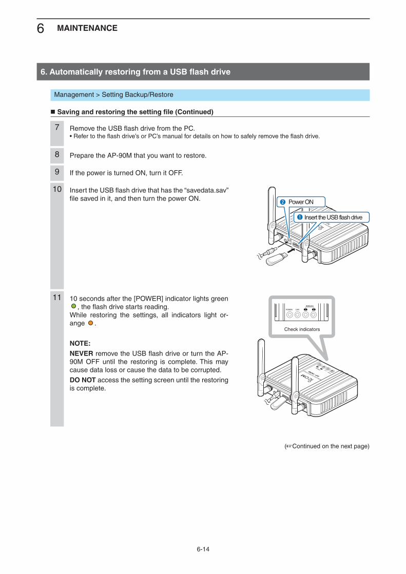
6 MAINTENANCE
6-14
Management > Setting Backup/Restore
Saving and restoring the setting file (Continued)
(+Continued on the next page)
Remove the USB flash drive from the PC.• Refer to the flash drive’s or PC’s manual for details on how to safely remove the flash drive.
7
Prepare the AP-90M that you want to restore.8
If the power is turned ON, turn it OFF.9
Insert the USB flash drive that has the “savedata.sav” file saved in it, and then turn the power ON.
10
10 seconds after the [POWER] indicator lights green , the flash drive starts reading.
While restoring the settings, all indicators light or-ange .
NOTE:NEVER remove the USB flash drive or turn the AP-90M OFF until the restoring is complete. This may cause data loss or cause the data to be corrupted.
DO NOT access the setting screen until the restoring is complete.
11
AP-90M
WIRELESS ACCESS POINTq
w
Insert the USB flash drive
Power ON
AP-90M
WIRELESS ACCESS POINT
Check indicators
6. Automatically restoring from a USB flash drive
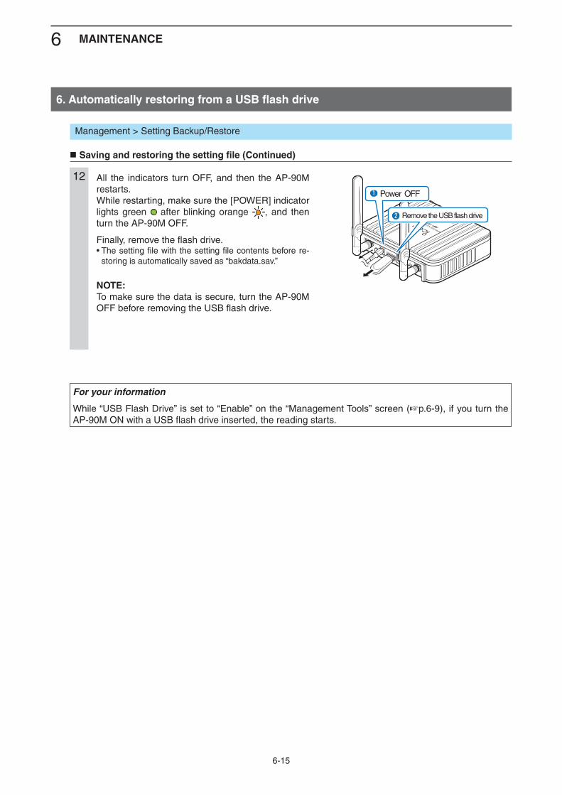
6 MAINTENANCE
6-15
Management > Setting Backup/Restore
Saving and restoring the setting file (Continued)
6. Automatically restoring from a USB flash drive
For your information
While “USB Flash Drive” is set to “Enable” on the “Management Tools” screen (+p.6-9), if you turn the AP-90M ON with a USB flash drive inserted, the reading starts.
All the indicators turn OFF, and then the AP-90M restarts.While restarting, make sure the [POWER] indicator lights green after blinking orange , and then turn the AP-90M OFF.
Finally, remove the flash drive.• The setting file with the setting file contents before re-
storing is automatically saved as “bakdata.sav.”
NOTE:To make sure the data is secure, turn the AP-90M OFF before removing the USB flash drive.
12
AP-90M
WIRELESS ACCESS POINTw
q
Remove the USB flash drive
Power OFF
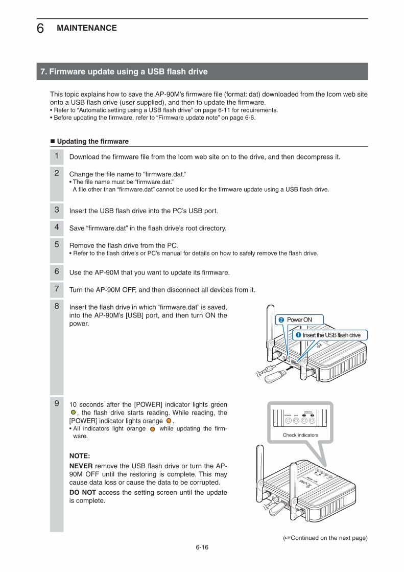
6 MAINTENANCE
6-16
(+Continued on the next page)
10 seconds after the [POWER] indicator lights green , the flash drive starts reading. While reading, the
[POWER] indicator lights orange .• All indicators light orange while updating the firm-
ware.
NOTE:NEVER remove the USB flash drive or turn the AP-90M OFF until the restoring is complete. This may cause data loss or cause the data to be corrupted.
DO NOT access the setting screen until the update is complete.
9
AP-90M
WIRELESS ACCESS POINT
Check indicators
This topic explains how to save the AP-90M’s firmware file (format: dat) downloaded from the Icom web site onto a USB flash drive (user supplied), and then to update the firmware.• Refer to “Automatic setting using a USB flash drive” on page 6-11 for requirements.• Before updating the firmware, refer to “Firmware update note” on page 6-6.
Updating the firmware
Download the firmware file from the Icom web site on to the drive, and then decompress it.1
Change the file name to “firmware.dat.”• The file name must be “firmware.dat.” A file other than “firmware.dat” cannot be used for the firmware update using a USB flash drive.
2
Insert the USB flash drive into the PC’s USB port.3
Save “firmware.dat” in the flash drive’s root directory.4
Remove the flash drive from the PC.• Refer to the flash drive’s or PC’s manual for details on how to safely remove the flash drive.
5
Use the AP-90M that you want to update its firmware.6
Turn the AP-90M OFF, and then disconnect all devices from it.7
Insert the flash drive in which “firmware.dat” is saved, into the AP-90M’s [USB] port, and then turn ON the power.
8
AP-90M
WIRELESS ACCESS POINTq
w
Insert the USB flash drive
Power ON
7. Firmware update using a USB flash drive
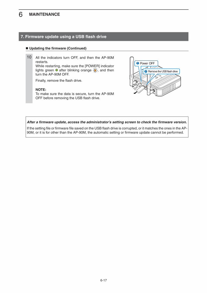
6 MAINTENANCE
6-17
All the indicators turn OFF, and then the AP-90M restarts.While restarting, make sure the [POWER] indicator lights green after blinking orange , and then turn the AP-90M OFF.
Finally, remove the flash drive.
NOTE:To make sure the data is secure, turn the AP-90M OFF before removing the USB flash drive.
10
AP-90M
WIRELESS ACCESS POINTw
q
Remove the USB flash drive
Power OFF
Updating the firmware (Continued)
7. Firmware update using a USB flash drive
After a firmware update, access the administrator’s setting screen to check the firmware version.
If the setting file or firmware file saved on the USB flash drive is corrupted, or it matches the ones in the AP-90M, or it is for other than the AP-90M, the automatic setting or firmware update cannot be performed.
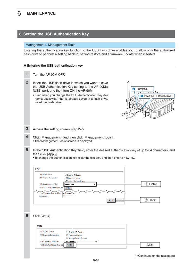
6 MAINTENANCE
6-18
Click [Management], and then click [Management Tools].• The “Management Tools” screen is displayed.
4
Turn the AP-90M OFF.1
Insert the USB flash drive in which you want to save the USB Authentication Key setting to the AP-90M’s [USB] port, and then turn ON the AP-90M.• Even when you change the USB Authentication Key (file
name: usbkey.dat) that is already saved in a flash drive, insert the flash drive.
2
AP-90M
WIRELESS ACCESS POINTq
w
Insert the USB flash drive
Power ON
In the “USB Authentication Key” field, enter the desired authentication key of up to 64 characters, and then click [Apply].• To change the authentication key, clear the text box, and then enter a new key.
5
Click [Write].6
Management > Management Tools
Entering the authentication key function to the USB flash drive enables you to allow only the authorized flash drive to perform a setting backup, setting restore and a firmware update when inserted.
Entering the USB authentication key
Access the setting screen. (+p.2-7)3
(+Continued on the next page)
8. Setting the USB Authentication Key
w Click
Click
q Enter
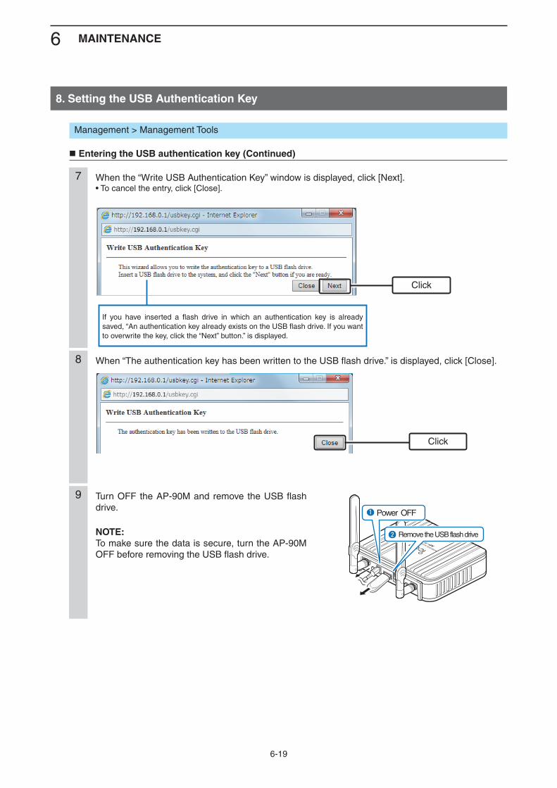
6 MAINTENANCE
6-19
When the “Write USB Authentication Key” window is displayed, click [Next].• To cancel the entry, click [Close].
7
When “The authentication key has been written to the USB flash drive.” is displayed, click [Close].8
If you have inserted a flash drive in which an authentication key is already saved, “An authentication key already exists on the USB flash drive. If you want to overwrite the key, click the “Next” button.” is displayed.
Management > Management Tools
Entering the USB authentication key (Continued)
Turn OFF the AP-90M and remove the USB flash drive.
NOTE:To make sure the data is secure, turn the AP-90M OFF before removing the USB flash drive.
9
AP-90M
WIRELESS ACCESS POINTw
q
Remove the USB flash drive
Power OFF
Click
Click
8. Setting the USB Authentication Key
1. Troubleshooting .........................................................................................................................................7-22. Connecting using Telnet ...........................................................................................................................7-4 M For Windows 7 ........................................................................................................................................7-4 M About the Telnet commands ...................................................................................................................7-43. About the setting screen...........................................................................................................................7-54. Feature functions.......................................................................................................................................7-7 M Wireless LAN system ..............................................................................................................................7-7 M Network Management system ................................................................................................................7-7 M Other features .........................................................................................................................................7-75. About the characters .................................................................................................................................7-8 M Network Settings .....................................................................................................................................7-8 M Wireless Settings ....................................................................................................................................7-8 M Management ...........................................................................................................................................7-86. Specifications ............................................................................................................................................7-9 M General ...................................................................................................................................................7-9 M Cable LAN ...............................................................................................................................................7-9 M Wireless LAN ..........................................................................................................................................7-9
INFORMATION 7
7 INFORMATION
Form2001
7-2
Form2001
1. Troubleshooting
The following conditions are not due to malfunctioning. Check before sending a request for repair.
The [POWER] indicator does not light
The power adapter is not connected. ➥
- Check the adapter or DC jack connection.The power adapter is connected to the power outlet interlocked with a PC. ➥
- Connect the power adapter to a different power outlet.
The [LAN] indicator does not light
The Ethernet cable is not properly connected to the AP-90M. ➥
- Make sure the Ethernet cable is securely connected.The HUB or PC is turned OFF. ➥
- Turn ON the HUB or PC.
The [WIRELESS] (1/2) indicator does not light green
The PC is not working properly. ➥
- Refer to the instruction manual of the PC or the wireless LAN adapter.The wireless LAN standards do not match between the wireless LAN station and the AP-90M. ➥
- Check the wireless LAN station’s wireless LAN standards.The wireless LAN function is disabled. ➥
- Enable the AP-90M’s wireless LAN function.The same frequency band is set to Wireless 1 and Wireless 2. ➥
- Set different frequency bands to Wireless 1 and Wireless 2.No radio communication is made for more than 4 minutes after the last communication. ➥
- Access the AP-90M again, and then make sure the indicators light.The AP-90M power was turned ON after turning ON the PC. ➥
- Restart the PC with the AP-90M power turned ON.The wireless LAN station’s communication mode is set to “Ad hoc.” ➥
- Set to “Infrastructure.”SSID is set incorrectly . ➥
- Check the SSID on both the AP-90M and wireless LAN station.The security mode is set incorrectly. ➥
- Set the same authentication mode to both the AP-90M and wireless LAN station.MAC address filtering is used. ➥
- Register the wireless LAN station’s MAC address to the AP-90M.The “Hide SSID” setting is enabled. ➥
- Disable the “Hide SSID” settings.
The [WIRELESS] (1/2) indicator lights green but cannot communicate
The encryption security is set incorrectly. ➥
- Check the encryption security settings for both the AP-90M and wireless LAN station.
The [WPS] button does not work (wireless LAN does not set automatically)
The WPS is set to “None.” ➥
- The WPS interface (ath0 to ath7) is not set or the interface number is set incorrectly. (+p.2-11)The automatic setting with other wireless LAN station is in process. ➥
- Wait until the automatic setting is complete.The automatic setting would not start after trying several times. ➥
- Disable the WPS function and set it manually.
7 INFORMATION
Form2001
7-3
1. Troubleshooting (Continued)
Cannot communicate with the [IEEE802.11n] or [IEEE802.11ac] standard
The wireless LAN station does not comply with the [IEEE802.11n] or [IEEE802.11ac] standard. ➥
- Use a wireless LAN station that complies with the standards.Encryption is not set to “AES.” ➥
- When communicating with the [IEEE802.11n] or [IEE802.11ac] standards, set the encryption to “AES” or disable the encryption.
The setting screen does not open properly
The JavaScript or Cookie functions are turned OFF. ➥
- Turn the functions ON. Your Microsoft Internet Explorer version is 8 or earlier, or your browser is other than Internet Explorer. ➥
- Use Microsoft Internet Explorer 9 or later.
Cannot access the AP-90M’s setting screen
The IP address is not set. ➥
- Set the PC’s IP address as a static IP address when accessing for the first time or after a reset. (+p.2-3)The wireless LAN settings for the PC and the AP-90M are different. ➥
- Set the same “Authentication” and “Encryption” to both the PC and the AP-90M.A proxy server is used for the web browser setting. ➥
- Set the web browser’s proxy server setting to OFF. Click the “Tools” in the web browser menu, and then click “Internet option.” Click the “Connections” tab, and click [LAN settings], and then confirm there is no check mark in “Automatically de-
tect settings” and “Use a proxy server for your LAN (These settings will not apply to dial-up on VPN connection).
Cannot change the settings on the AP-90M’s setting screen
The “Management Tools” is enabled, and the RS-AP3 is used. ➥
- Change the settings in the RS-AP3. - Complete the RS-AP3 settings, and then change the settings on the AP-90M.
Cannot operate the AP-90M using the RS-AP3
The “Management Tools” is disabled. ➥
- Select “Enable” for the “Management Tools.”The AP-90M’s IP address is not set to the RS-AP3 correctly. ➥
- Check the IP address, and set it correctly.The LAN cable is not connected properly. ➥
- Check the [LAN] port or the LAN cable connections.
Cannot use the wireless bridging function in Wireless 1 (internal antenna)
A DFS function channel or “Automatic” is selected for “Channel.” ➥
- Check the channel.The Shared Key “PSK: Pre-Shared Key” differs from the key set to the peer unit. ➥
- Check the shared key set to the peer unit.The peer unit’s BSSID is not registered correctly for the wireless bridging function. ➥
- Check the BSSID registered to the peer unit.
Cannot use the wireless bridging function in Wireless 2 (external antenna)
A DFS function channel is selected for the AP-90M (master unit), or a DFS function required channel is se- ➥
lected on an “Automatic” channel. - Check the channel used.
The client’s encryption setting differs from the master unit’s Virtual AP (ath4). ➥
- Check the master unit’s encryption setting.The client’s SSID differs from the master unit’s Virtual AP (ath4). ➥
- Check the master unit’s SSID.The client’s BSSID is not correctly registered to the master unit. ➥
- Check the client’s BSSID.
7 INFORMATION
Form2001
7-4
2. Connecting using Telnet
This topic explains how to connect using Telnet.
M For Windows 7
To use Telnet, access [Control Panel], [Programs], [Turn Windows features on or off] and enable [Telnet cli-ent], and then follow the steps below.
How to set1. Start up Windows.
2. Click the [Start] button, and then select [Search programs and files]. Type-in “telnet.exe” and push [Enter].
3. When the telnet screen appears, enter as follows. Microsoft Telnet> “open” and IP address. (Example: open 192.168.0.1)
4. Enter as follows, and then push [Enter] to log in. login: admin password: admin • “admin” is set as default. • Enter the administrator’s password set on the setting screen.
5. If Telnet can access the AP-90M, “AP-90M #” is displayed on the Telnet screen.
M About the Telnet commands
The following commands can be used for the Telnet function.
Command list: Push the [Tab] key to display the telnet command list. After typing a telnet command, push the [Tab] key to display the sub command
list.
Command help: After typing “help,” enter a command to display the command description. (Example) “help save” (“save” command description is displayed.)
Automatic complement: After typing first few characters of the command, push the [Tab] key. The rest of the characters for the command are automatically entered.
(Example) “n” + [Tab] -> network Suggested commands are displayed. (Example) “res” + [Tab] -> reset restart
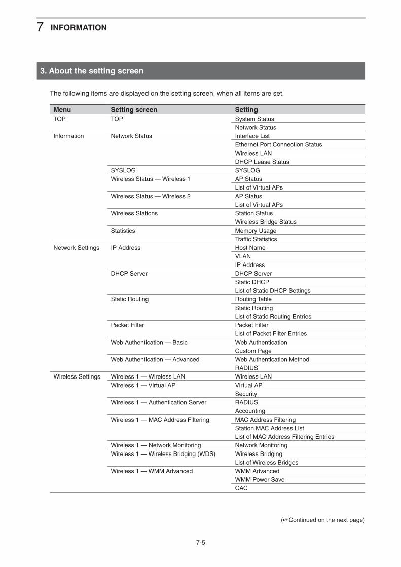
7 INFORMATION
Form2001
7-5
3. About the setting screen
The following items are displayed on the setting screen, when all items are set.
Menu Setting screen SettingTOP TOP System Status
Network StatusInformation Network Status Interface List
Ethernet Port Connection StatusWireless LANDHCP Lease Status
SYSLOG SYSLOGWireless Status — Wireless 1 AP Status
List of Virtual APsWireless Status — Wireless 2 AP Status
List of Virtual APsWireless Stations Station Status
Wireless Bridge StatusStatistics Memory Usage
Traffic StatisticsNetwork Settings IP Address Host Name
VLANIP Address
DHCP Server DHCP ServerStatic DHCPList of Static DHCP Settings
Static Routing Routing TableStatic RoutingList of Static Routing Entries
Packet Filter Packet FilterList of Packet Filter Entries
Web Authentication — Basic Web AuthenticationCustom Page
Web Authentication — Advanced Web Authentication MethodRADIUS
Wireless Settings Wireless 1 — Wireless LAN Wireless LANWireless 1 — Virtual AP Virtual AP
SecurityWireless 1 — Authentication Server RADIUS
AccountingWireless 1 — MAC Address Filtering MAC Address Filtering
Station MAC Address ListList of MAC Address Filtering Entries
Wireless 1 — Network Monitoring Network MonitoringWireless 1 — Wireless Bridging (WDS) Wireless Bridging
List of Wireless BridgesWireless 1 — WMM Advanced WMM Advanced
WMM Power SaveCAC
(+Continued on the next page)
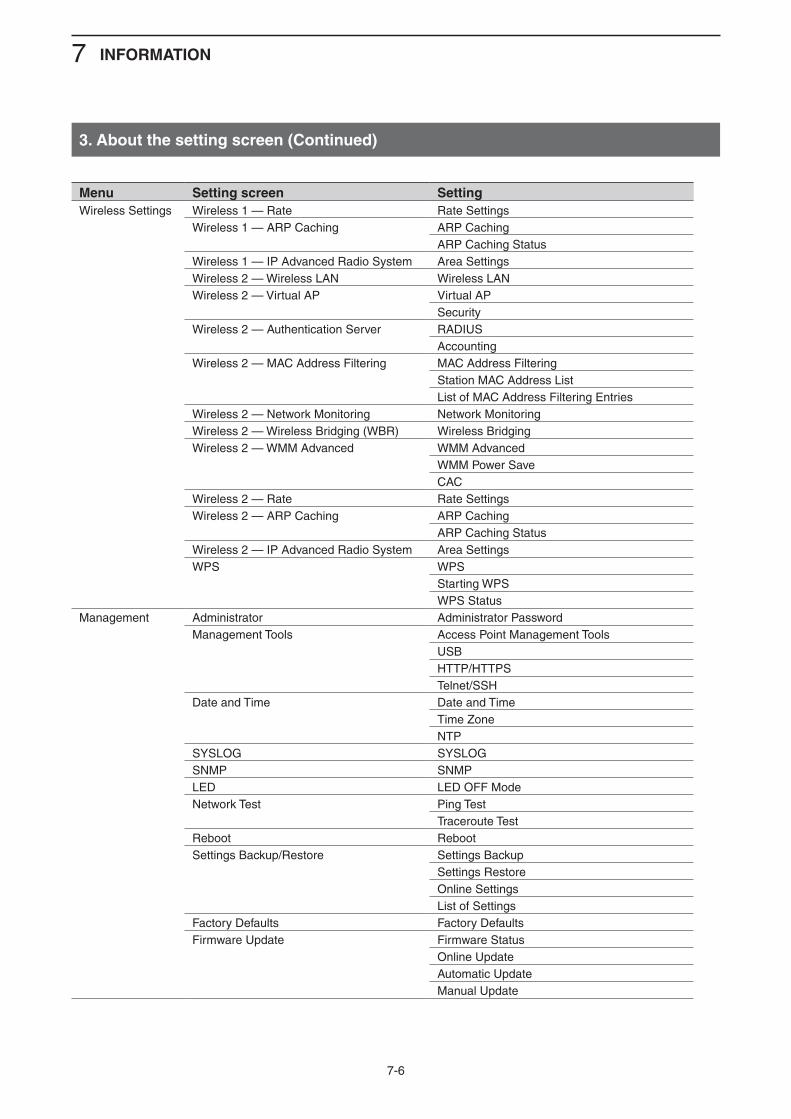
7 INFORMATION
Form2001
7-6
Menu Setting screen SettingWireless Settings Wireless 1 — Rate Rate Settings
Wireless 1 — ARP Caching ARP CachingARP Caching Status
Wireless 1 — IP Advanced Radio System Area SettingsWireless 2 — Wireless LAN Wireless LANWireless 2 — Virtual AP Virtual AP
SecurityWireless 2 — Authentication Server RADIUS
AccountingWireless 2 — MAC Address Filtering MAC Address Filtering
Station MAC Address ListList of MAC Address Filtering Entries
Wireless 2 — Network Monitoring Network MonitoringWireless 2 — Wireless Bridging (WBR) Wireless BridgingWireless 2 — WMM Advanced WMM Advanced
WMM Power SaveCAC
Wireless 2 — Rate Rate SettingsWireless 2 — ARP Caching ARP Caching
ARP Caching StatusWireless 2 — IP Advanced Radio System Area SettingsWPS WPS
Starting WPSWPS Status
Management Administrator Administrator PasswordManagement Tools Access Point Management Tools
USBHTTP/HTTPSTelnet/SSH
Date and Time Date and TimeTime ZoneNTP
SYSLOG SYSLOGSNMP SNMPLED LED OFF ModeNetwork Test Ping Test
Traceroute TestReboot RebootSettings Backup/Restore Settings Backup
Settings RestoreOnline SettingsList of Settings
Factory Defaults Factory DefaultsFirmware Update Firmware Status
Online UpdateAutomatic UpdateManual Update
3. About the setting screen (Continued)
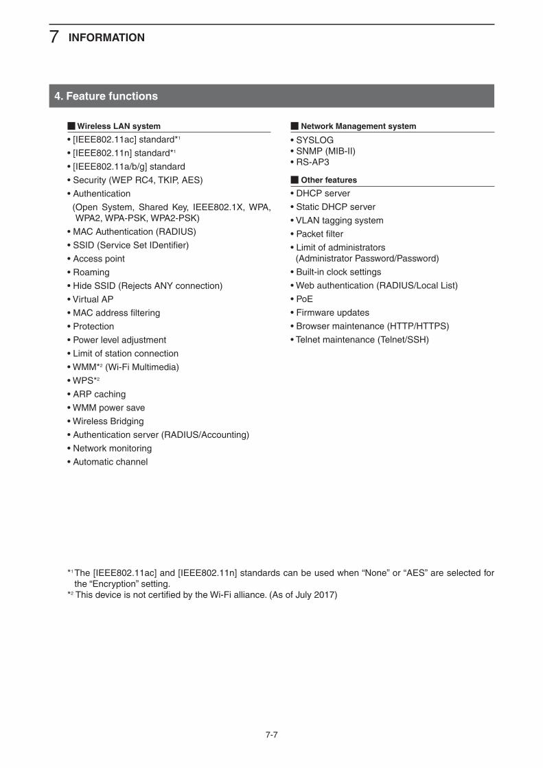
7 INFORMATION
Form2001
7-7
4. Feature functions
M Wireless LAN system
• [IEEE802.11ac] standard*1
• [IEEE802.11n] standard*1
• [IEEE802.11a/b/g] standard
• Security (WEP RC4, TKIP, AES)
• Authentication
( Open System, Shared Key, IEEE802.1X, WPA, WPA2, WPA-PSK, WPA2-PSK)
• MAC Authentication (RADIUS)
• SSID (Service Set IDentifier)
• Access point
• Roaming
• Hide SSID (Rejects ANY connection)
• Virtual AP
• MAC address filtering
• Protection
• Power level adjustment
• Limit of station connection
• WMM*2 (Wi-Fi Multimedia)
• WPS*2
• ARP caching
• WMM power save
• Wireless Bridging
• Authentication server (RADIUS/Accounting)
• Network monitoring
• Automatic channel
M Network Management system
• SYSLOG• SNMP (MIB-II)• RS-AP3
M Other features
• DHCP server
• Static DHCP server
• VLAN tagging system
• Packet filter
• Limit of administrators (Administrator Password/Password)
• Built-in clock settings
• Web authentication (RADIUS/Local List)
• PoE
• Firmware updates
• Browser maintenance (HTTP/HTTPS)
• Telnet maintenance (Telnet/SSH)
*1 The [IEEE802.11ac] and [IEEE802.11n] standards can be used when “None” or “AES” are selected for the “Encryption” setting.
*2 This device is not certified by the Wi-Fi alliance. (As of July 2017)
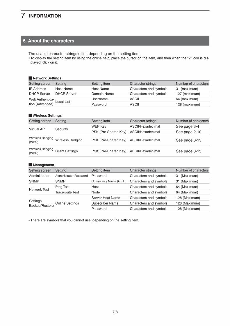
7 INFORMATION
Form2001
7-8
5. About the characters
The usable character strings differ, depending on the setting item.• To display the setting item by using the online help, place the cursor on the item, and then when the “?” icon is dis-
played, click on it.
M Network Settings
Setting screen Setting Setting item Character strings Number of characters
IP Address Host Name Host Name Characters and symbols 31 (maximum)DHCP Server DHCP Server Domain Name Characters and symbols 127 (maximum)
Web Authentica-tion (Advanced)
Local ListUsername ASCII 64 (maximum)
Password ASCII 128 (maximum)
M Wireless Settings
Setting screen Setting Setting item Character strings Number of characters
Virtual AP SecurityWEP Key ASCII/Hexadecimal See page 3-4PSK (Pre-Shared Key) ASCII/Hexadecimal See page 2-10
Wireless Bridging(WDS)
Wireless Bridging PSK (Pre-Shared Key) ASCII/Hexadecimal See page 3-13
Wireless Bridging(WBR)
Client Settings PSK (Pre-Shared Key) ASCII/Hexadecimal See page 3-15
M Management
Setting screen Setting Setting item Character strings Number of characters
Administrator Administrator Password Password Characters and symbols 31 (Maximum)
SNMP SNMP Community Name (GET) Characters and symbols 31 (Maximum)
Network TestPing Test Host Characters and symbols 64 (Maximum)
Traceroute Test Node Characters and symbols 64 (Maximum)
SettingsBackup/Restore
Online Settings
Server Host Name Characters and symbols 128 (Maximum)
Subscriber Name Characters and symbols 128 (Maximum)
Password Characters and symbols 128 (Maximum)
• There are symbols that you cannot use, depending on the setting item.
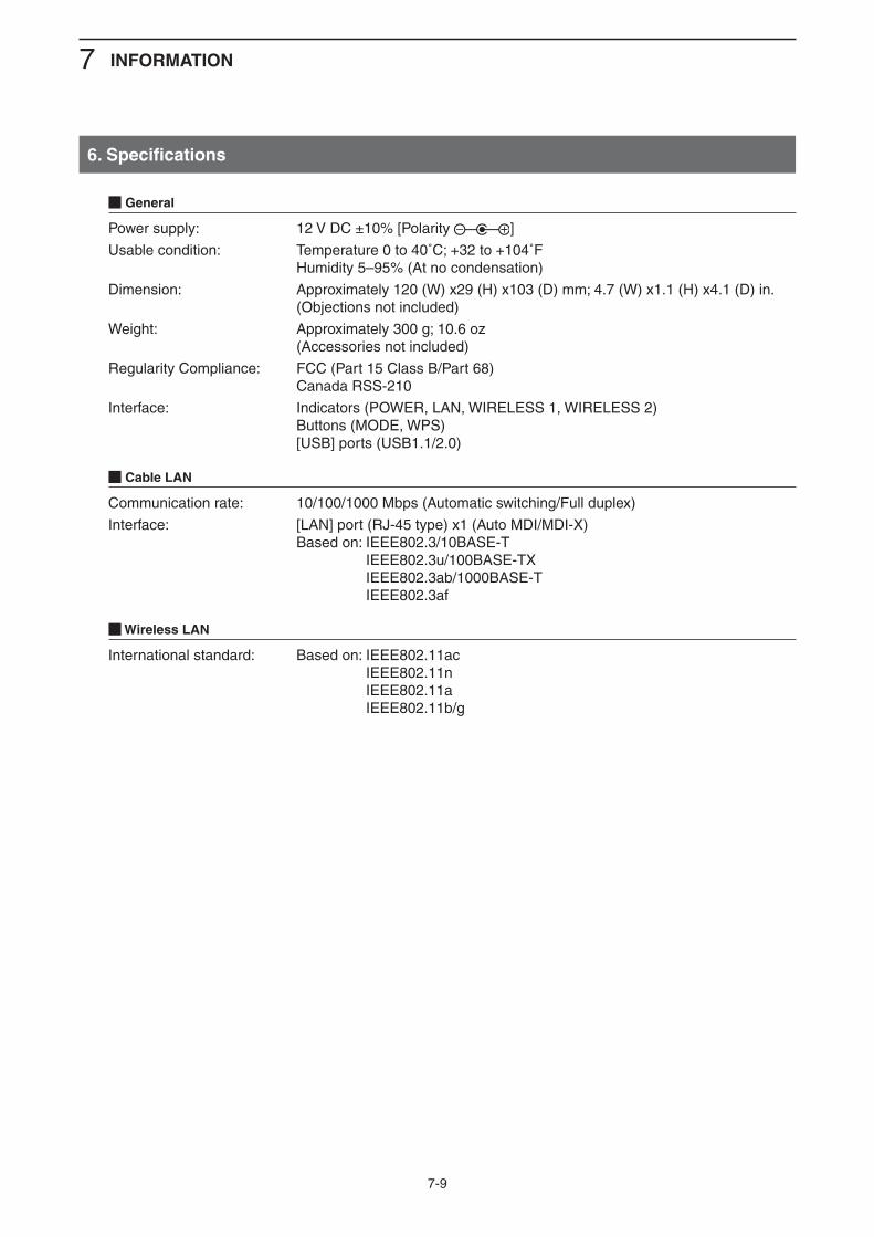
7 INFORMATION
Form2001
7-9
6. Specifications
M General
Power supply: 12 V DC ±10% [Polarity ]
Usable condition: Temperature 0 to 40˚C; +32 to +104˚F Humidity 5–95% (At no condensation)
Dimension: Approximately 120 (W) x29 (H) x103 (D) mm; 4.7 (W) x1.1 (H) x4.1 (D) in. (Objections not included)
Weight: Approximately 300 g; 10.6 oz (Accessories not included)
Regularity Compliance: FCC (Part 15 Class B/Part 68) Canada RSS-210
Interface: Indicators (POWER, LAN, WIRELESS 1, WIRELESS 2) Buttons (MODE, WPS) [USB] ports (USB1.1/2.0)
M Cable LAN
Communication rate: 10/100/1000 Mbps (Automatic switching/Full duplex)
Interface: [LAN] port (RJ-45 type) x1 (Auto MDI/MDI-X) Based on: IEEE802.3/10BASE-T
IEEE802.3u/100BASE-TX IEEE802.3ab/1000BASE-T IEEE802.3af
M Wireless LAN
International standard: Based on: IEEE802.11ac IEEE802.11n IEEE802.11a IEEE802.11b/g

1-1-32 Kamiminami, Hirano-ku, Osaka 547-0003, JapanA7168-3EX-1© 2015–2017 Icom Inc.