Embed Size (px)
Citation preview

Be sure to read this installer reference guide before conducting the installation of this product.
WIRED REMOTECONTROLLER
INSTALLER REFERENCE GUIDE
BRC073A1
Installer reference guide BRC073A1
1 4P392225-1 – 2014.11
Contents
Contents
1. About this document ......................................... 2
2. Safety Precautions ............................................. 2
3. Accessories ........................................................ 5
4. User interface installation procedure .............. 5
5. Functions and menu items of the user interface buttons ................................... 11
6. Power-on ........................................................... 14
7. Field settings .................................................... 15
8. Test operation method (pair split only) .......... 17
9. Checking procedure of Error History ............. 21
10. Registration method of the Maintenance Contact information ................ 22
11. Confirmation of registered details ................ 23
12. Clock & Calendar ........................................... 24
13. Language ........................................................ 25
14. Prohibit Buttons ............................................. 26
15. Function Prohibition ...................................... 27
16. Prohibit Mode ................................................. 28
17. Software update with Updater ...................... 30
BRC073A1 Installer reference guide4P392225-1 – 2014.11 2
About this document
1. About this documentTarget audienceAuthorized installers
Documentation setThis document is part of a documentation set. The complete set consists of:
Document Contains... FormatInstallation and operation manual
Installation and operation instructions Paper (in the box)
Installer reference guidePreparation of the installation, technical specifications, reference data,.. Digital files on http://www.
daikineurope.com/support-and-manuals/product-information/
User reference guide
Detailed step-by-step instructions and background information for basic and advanced usage
Latest revisions of the supplied documentation may be available on the regional Daikin web site or via our dealer.For detailed instructions refer to the installation videos available on http://www.daikineurope.com/support-and-manuals/product-information/. More specifically, for how to connect the S21 connector, refer to the installation videos of the Daikin online controller.
2. Safety PrecautionsThe original instructions are written in English. All other languages are translations of the original instructions.
� Also see the installation manual attached to the indoor unit.
Please read these Safety Precautions carefully before installing the user interface.
● This manual classifies the precautions into WARNING and CAUTION. They both contain important information regarding safety. Be sure to follow all the precautions below.
WARNING Failure to follow these instructions properly may result in personal injury or loss of life.
CAUTIONFailure to observe these instructions properly may result in property damage or personal injury, which may be serious depending on the circumstances.
● After completing the installation, conduct a trial operation to check for faults and explain to the customer how to operate the air conditioner with the aid of the User reference guide. Ask the customer to store the Installer reference guide along with the User reference guide for future reference.

Installer reference guide BRC073A1
3 4P392225-1 – 2014.11
Safety Precautions
WARNINGAsk your dealer or qualified personnel to carry out installation work. Do not attempt to install the user interface yourself. Improper installation may result in water leakage, electric shocks or fire.Consult your local dealer regarding relocation and reinstallation of the user interface. Improper installation work may result in leakage, electric shocks or fire hazards.Install the user interface in accordance with the instructions in this Installer reference guide. Improper installation may result in water leakage, electric shocks or fire.Be sure to use only the specified accessories and parts for installation work. Failure to use the specified parts may result in the unit falling down, water leakage, electric shocks or fire.Install the user interface on a foundation strong enough to withstand the weight of the user interface. Insufficient strength may result in the user interface falling down and causing injury.Electrical work must be performed in accordance with the relevant local and national regulations and with the instructions in this Installer reference guide. Be sure to use a dedicated power supply circuit only. Insufficient power circuit capacity and improper workmanship may result in electric shocks or fire.Always perform installation work with the power turned off.Touching electric parts may result in electric shock.Do not disassemble, reconstruct or repair.This may result in electric shock and/or fire.Make sure that all wiring is secured, the specified wires are used and that there is no strain on the terminal connections or wires. Improper connections or securing of wires may result in abnormal heat build-up or fire.The choice of materials and installations must comply with the applicable national and international standards.

BRC073A1 Installer reference guide4P392225-1 – 2014.11 4
Safety Precautions
CAUTIONTo avoid leakage and electric shock due to entry of water or insects, fill the wiring through hole with putty.To avoid electric shocks, do not operate with wet hands.Do not wash the user interface with water, as this may result in electric shocks or fire.Install the indoor and outdoor units, power cord and connection wires at least 1 meter away from televisions or radios to prevent interference and noise. (Depending on the incoming signal strength, a distance of 1 meter may not be sufficient to eliminate noise.)Do not install the air conditioner in the following locations:
1. Where there is a high concentration of mineral oil spray or vapour (e.g. a kitchen). Plastic parts may deteriorate and fall off which could result in water leakage.
2. Where corrosive gas, such as sulphurous acid gas, is produced. Corroding of copper pipes or soldered parts may result in refrigerant leakage.
3. Near machinery emitting electromagnetic radiation. Electromagnetic radiation may disturb the operation of the control system and result in malfunctioning of the unit.
4. Where flammable gas may leak, where there is carbon fibre or ignitable dust suspensions in the air or where volatile flammables such as paint thinner or gasoline are handled. Operating the unit in such conditions may result in fire.
5. High temperature areas or direct flames. Overheating and/or fire may occur.
6. Moist areas or places which may be exposed to water. If water enters the user interface, electric shock may be caused and the inner electronics may fail.
When the thermostat function of the user interface is used, select the installation location while considering it should be a place:
● Where the average temperature in the room can be detected. ● Which is not exposed to direct sunlight. ● Which is not near a heat source. ● Which is not affected by the outside air or air draught due to, for example, opening/closing of
doors, the air outlet of the indoor unit or the like. ● Which is NOT located outdoors.
Installer reference guide BRC073A1
5 4P392225-1 – 2014.11
Accessories
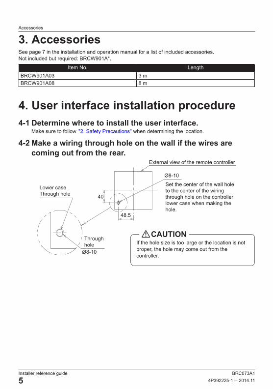
3. AccessoriesSee page 7 in the installation and operation manual for a list of included accessories.Not included but required: BRCW901A*.
Item No. LengthBRCW901A03 3 mBRCW901A08 8 m
4. User interface installation procedure4-1 Determine where to install the user interface.
Make sure to follow "2. Safety Precautions" when determining the location.
4-2 Make a wiring through hole on the wall if the wires are coming out from the rear.
Set the center of the wall hole to the center of the wiring through hole on the controller lower case when making the hole.
40
48.5
Lower case Through hole
Ø8-10
Through hole
External view of the remote controller
Ø8-10
If the hole size is too large or the location is not proper, the hole may come out from the controller.
CAUTION

BRC073A1 Installer reference guide4P392225-1 – 2014.11 6
User interface installation procedure
4-3 Determine the direction of the controller wiring outlet (rear outlet, left outlet, top left outlet).4-3-1 Rear outlet 4-3-2 Left outlet
Cut off the resin area (hatched area). Cut off the thin area (hatched area) with nippers or the like and then remove the burrs with a file or the like.
4-3-3 Top left outlet
Cut off the thin area (hatched area) with nippers or the like and then remove the burrs with a file or the like.
Installer reference guide BRC073A1
7 4P392225-1 – 2014.11
User interface installation procedure
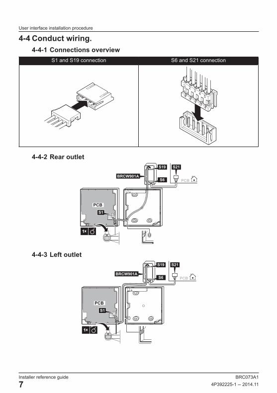
4-4 Conduct wiring.4-4-1 Connections overview
S1 and S19 connection S6 and S21 connection
23
45
H JS
T
4-4-2 Rear outlet
1×
PCB
PCB
S19 S21
S6
S1
1×
BRCW901A
4-4-3 Left outlet
PCB
1×
PCB
S19 S21
S6
S1
BRCW901A

BRC073A1 Installer reference guide4P392225-1 – 2014.11 8
User interface installation procedure
4-4-4 Top left outlet
1×
PCB
S19 S21
S6
S1
PCB
BRCW901A
● Do not perform wiring close to a power line in order to avoid electrical noise (external noise).
● Seal the wiring draw-in port securely with putty (field supply) to prevent the entry of insects or the like.
CAUTION
● The adapter does not provide any form of strain release. The installer must provide something to release the strain on the cables near the adapter.
CAUTION
● Earth both ends of the BRCW901A* option cable.NOTICE
4-5 Fixing procedure of the lower case.In the case of wiring a user interface through the rear outlet, perform the wiring through the outlet hole in the lower case before it is installed on the wall.
4-5-1 Wall mountingSecure by using the attached wood screws (2×).
Wood screws(Ø3.5×16)

Installer reference guide BRC073A1
9 4P392225-1 – 2014.11
User interface installation procedure
4-5-2 Switchbox mountingSecure by using the attached small screws (2×).
(Installation pitch)
46
84
Switchbox for two units (with no cover) Switchbox
(field supply)(Use optional accessory KJB211A)
Small screws (M4×16)
(Installation pitch)
28
84
Switchbox for one unit (with no cover)
Small screws (M4×16)
Switchbox(field supply)(Use optional accessory KJB111A)
● Select a flat surface for installation if possible. ● Do not tighten the installation screws too much to avoid deforming the lower case.
CAUTION
BRC073A1 Installer reference guide4P392225-1 – 2014.11 10
User interface installation procedure
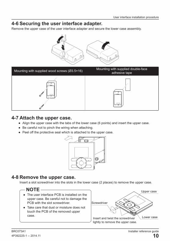
4-6 Securing the user interface adapter.Remove the upper case of the user interface adapter and secure the lower case assembly.
31
2
Mounting with supplied wood screws (Ø3.5×16) Mounting with supplied double-face adhesive tape
4-7 Attach the upper case. ● Align the upper case with the tabs of the lower case (6 points) and insert the upper case. ● Be careful not to pinch the wiring when attaching. ● Peel off the protective seal which is attached to the upper case.
4-8 Remove the upper case. Insert a slot screwdriver into the slots in the lower case (2 places) to remove the upper case.
● The user interface PCB is installed on the upper case. Be careful not to damage the PCB with the slot screwdriver.
● Take care that dust or moisture does not touch the PCB of the removed upper case.
NOTE
Insert and twist the screwdriverlightly to remove the upper case.
Screwdriver
Lower case
Upper case

Installer reference guide BRC073A1
11 4P392225-1 – 2014.11
Functions and menu items of the user interface buttons
5. Functions and menu items of the user interface buttons
5-1 Functions and menu items(1) Operation Mode Selector button(11) LCD (with backlight)
(4) Up button(5) Down button(6) Right button(7) Left button
(9) Operation lamp
(8) On/Off button
(10) Cancel button
(2) Fan Speed/Airflow direction button
(3) Menu/Enter button
(1) Operation Mode Selector button ● This button is enabled by default. To disable, refer to "14. Prohibit Buttons" on page 26.
● Press this button to select the operation mode of your preference.
● Available modes may vary with the connected model.
(2) Fan Speed/Airflow direction button ● Used to change the fan speed and airflow direction.
● Available fan speeds and airflow directions may vary with the connected model.
(3) Menu/Enter button ● This button is enabled by default. To disable, refer to "5-2 Enable/disable the Menu/Enter and Cancel button" on page 13.
● Used to display the main menu or enter the selected item. (For details on the main menu, see the User reference guide.)
Main menu*
Airflow DirectionEnergy Saving OptionsScheduleMaintenance InformationConfigurationCurrent SettingsClock & CalendarLanguage
(4) Up button ● Used to raise the set temperature. ● The next item on the upper side will be highlighted. (Keep pressing the button to cycle through the values or items.)
● Used to change the selected item.

BRC073A1 Installer reference guide4P392225-1 – 2014.11 12
Functions and menu items of the user interface buttons
(5) Down button ● Used to lower the set temperature. ● The next item on the lower side will be highlighted. (Keep pressing the button to cycle through the values or items.)
● Used to change the selected item.(6) Right button
● Used to highlight the next item on the right-hand side.
● The display contents are changed to the next screen.
(7) Left button ● Used to highlight the next items on the left-hand side.
● The display contents are changed to the previous screen.
(8) On/Off button ● Press to start or stop the air conditioner.
(9) Operation lamp (Green) ● This lamp lights up during operation. ● This lamp will blink if an error or mode conflict occurs.
● This lamp is not lit when the unit operation is OFF.
(10) Cancel button ● Used to return to the previous screen. ● Press and hold this button for 4 seconds or longer to display the Service Settings menu.
(11) LCD (with backlight) ● The backlight will be lit for approximately 30 seconds when one of the buttons is pressed.
● The actions linked to the buttons, except for the On/Off button, are not carried out when the backlight is not lit.
Service Settings menu*
Test Operation**Maintenance ContactField SettingsError History
* Available menu items are depending on the connected model.
** Not displayed in case of multi-split setup.
● To operate the Up/Down/Left/Right button, always press , , , or .CAUTION
Installer reference guide BRC073A1
13 4P392225-1 – 2014.11
Functions and menu items of the user interface buttons
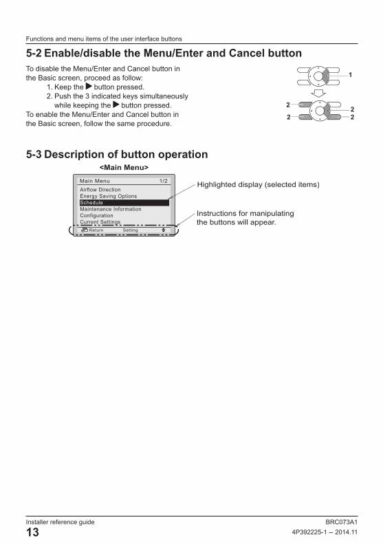
5-2 Enable/disable the Menu/Enter and Cancel buttonTo disable the Menu/Enter and Cancel button in the Basic screen, proceed as follow:
1. Keep the button pressed.2. Push the 3 indicated keys simultaneously
while keeping the button pressed.To enable the Menu/Enter and Cancel button in the Basic screen, follow the same procedure.
2
222
1
5-3 Description of button operation
Instructions for manipulating the buttons will appear.
<Main Menu>
Highlighted display (selected items)Airflow DirectionEnergy Saving OptionsScheduleMaintenance InformationConfigurationCurrent Settings
1/2Main Menu
SettingReturn
BRC073A1 Installer reference guide4P392225-1 – 2014.11 14
Power-on
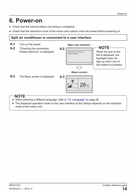
6. Power-on ● Check that the indoor/outdoor unit wiring is completed.
● Check that the switchbox cover of the indoor and outdoor units are closed before powering on.
Split air conditioner is connected to a user interface
6-1 Turn on the power. <Main user interface>6-2 "Checking the connection.
Please stand by." is displayed.6-2
Checking the connection.Please stand by.
When the text on the left is displayed, the backlight does not light up when one of the buttons is pressed.
NOTE
<Basic screen>
6-3 The Basic screen is displayed. 6-3
28°C
● When selecting a different language, refer to "13. Language" on page 25. ● The displayed operation mode on the user interface at first startup depends on the operation
mode of the indoor unit.
NOTE
Installer reference guide BRC073A1
15 4P392225-1 – 2014.11
Field settings
7. Field settings<Basic screen>
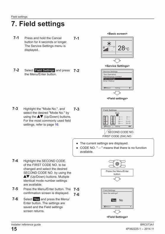
7-1 Press and hold the Cancel button for 4 seconds or longer. The Service Settings menu is displayed.
7-1
28°C
<Service Settings>7-2 Select Field Settings and press
the Menu/Enter button.7-2
Test OperationMaintenance ContactField SettingsError History
Service Settings
SettingReturn
<Field settings>
7-3 Highlight the "Mode No.", and select the desired "Mode No." by using the (Up/Down) buttons. For the most commonly used field settings, refer to page 16.
7-3 Field SettingsMode
1b
SettingReturn
● The current settings are displayed. ● CODE NO. " -- " means that there is no function
available.
7-4 Highlight the SECOND CODE. of the FIRST CODE NO. to be changed and select the desired SECOND CODE NO. by using the
(Up/Down) buttons. Multiple identical mode number settings are available.
Press the Menu/Enter button.
7-5 Press the Menu/Enter button. The confirmation screen is displayed.
7-6 Select Yes and press the Menu/Enter button. The settings are saved and the Field settings screen returns.
7-57-6
NoYes
Field SettingsSave the settings?
SettingReturn
<Field Settings>
FIRST CODE (SW) NO.SECOND CODE NO.

BRC073A1 Installer reference guide4P392225-1 – 2014.11 16
Field settings
7-7 After all changes are completed, press the Cancel button twice.
7-8 The backlight goes out and "Checking the connection. Please stand by" is displayed during initialization. After the initialization, the Basic screen returns.
Mode No.
(Note 1)
FIRST CODE
NO.Description of the setting
SECOND CODE NO. (Note 2)
01 02 03 04
1b 13 Icon or Icon+Text on Basic screen Icon+Text Icon — —
1e 2 Setback function. Do not use Heat only Cool onlyCool and Heat

Installer reference guide BRC073A1
17 4P392225-1 – 2014.11
Test operation method (pair split only)
8. Test operation method (pair split only) ∗ In case of multi-split models, see the manual attached to the outdoor unit.
● In case of multi-split setup, test operation cannot be used.NOTE
Also see the installation manuals attached to the indoor unit and the outdoor unit.
● Check that the wiring of the indoor unit and the outdoor unit is completed. ● Check that the switchbox cover of the indoor unit and the outdoor unit is closed. ● After refrigerant piping, drain piping and electric wiring are completed, clean the inside of the indoor
unit and the decorative panel. ● Perform the test operation according to the following procedure.
● The backlight will be lit for approximately 30 seconds when pressing one of the operation buttons.
● Operate the buttons only when the backlight is lit. However, the On/Off button can be operated when the backlight is not lit.
NOTE
8-1 Make sure to turn on the power at least 6 hours before starting test operation to protect the compressor.
Make sure that the outer panel and piping cover are closed before operation (danger of electric shock).
CAUTION
8-2 Confirm that both the liquid and gas stop valves are opened.
After the air purge of the vacuum pump, the refrigerant pressure may not rise even though the stop valve is opened. The reason is that the refrigerant system of the outdoor unit is blocked by the electrical expansion valve or the like. Operation is no problem.
NOTE
<Basic screen>8-3 Set the operation mode to cooling by
using the Operation Mode Selector button.
8-4 Press and hold the Cancel button for 4 seconds or longer. The Service Settings menu is displayed.
8-38-4
28°C
<Service Settings>
Press and hold the Cancel button for 4 seconds or
longer while the backlight is lit.

BRC073A1 Installer reference guide4P392225-1 – 2014.11 18
Test operation method (pair split only)
8-5 Select Test Operation and press the Menu/Enter button. The Basic screen returns and "Test operation" is displayed.
8-5Test OperationMaintenance ContactField SettingsError History
Service Settings
SettingReturnPress the Menu/Enter
button.
8-6 Press the On/Off button within about 10 seconds. Test operation starts. Check the operation condition for 3 minutes.
Test operation can also be started by first performing 8-6, followed by 8-5.
NOTE
8-6
Test Operation
Press the On/Off button (within 10 seconds).
<Main menu>8-7 Press the Menu/Enter button in the
Basic screen. The Main menu is displayed.
8-7
SettingReturn
Airflow DirectionEnergy Saving OptionsScheduleMaintenance InformationConfigurationCurrent Settings
1/2Main Menu
Press the Menu/Enter button.
8-8 Select Airflow Direction and press the Menu/Enter button.
8-9 Press the buttons to select the desired airflow direction and press the Menu/Enter button. The Basic screen returns.
8-88-9
Return SettingReturn Setting
Swing stop
Air�ow Direction
Swing stopDirection1 Direction2
Change the airflow direction using the (Up/Down)
buttons.
Press the Menu/Enter button.
8-10 Press and hold the Cancel button for 4 seconds or longer in the Basic screen. The Service Settings menu is displayed.
8-10
Test Operation
<Service Settings menu>
Press and hold the Cancel button for 4 seconds or
longer while the backlight is lit.

Installer reference guide BRC073A1
19 4P392225-1 – 2014.11
Test operation method (pair split only)
8-11 Select Test Operation in the Service Settings menu and press the Menu/Enter button. The Basic screen returns and normal operation is possible.
8-11Test OperationMaintenance ContactField SettingsError History
Service Settings
SettingReturn
<Basic screen>
Press the Menu/Enter button.
8-12 Check the functions according to the User reference guide.
8-13 When the decoration panel is not installed, turn off the power after test operation finishes.
Test operation will automatically finish after 30 minutes.
NOTE
● If the interior work is not completed when the test operation is finished, explain to the customer that he should not operate the unit until the interior work is completed in order to protect the indoor unit.
● (If the indoor unit is operated, the indoor unit may be contaminated with the materials which arise from paints or adhesives during the interior work and water splash or water leak may occur.)
CAUTION
● If it is not possible to operate the unit due to any malfunction, refer to Malfunction diagnosis method .
● When the test operation finishes, check that the error code history is not displayed in the Maintenance Information screen according to the following procedure.
CAUTION
<Basic screen>8-14 Press the Menu/Enter button in the
Basic screen. The Main menu is displayed.
8-14
28°C
<Main menu>
Press the Menu/Enter button.
8-15 Select Maintenance Information and press the Menu/Enter button.
8-15
SettingReturn
Airflow DirectionEnergy Saving OptionsScheduleMaintenance Information ConfigurationCurrent Settings
1/2Main Menu
Press the Menu/Enter button.
BRC073A1 Installer reference guide4P392225-1 – 2014.11 20
Test operation method (pair split only)
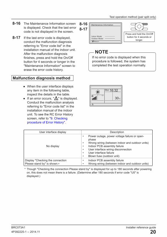
8-16 The Maintenance Information screen is displayed. Check that the last error code is not displayed in the screen.
8-17 If the last error code is displayed, conduct the malfunction diagnosis referring to "Error code list" in the installation manual of the indoor unit. After the malfunction diagnosis finishes, press and hold the On/Off button for 4 seconds or longer in the "Maintenance Information" screen to erase the error code history.
8-168-17
Indoor Model ––––––––––Outdoor Model ––––––––––
Maintenance Information
Return
If no error code is displayed when this procedure is followed, the system has completed the test operation normally.
NOTE
Press and hold the On/Off button for 4 seconds or
longer.
Malfunction diagnosis method
● When the user interface displays any item in the following table, inspect the details in the table.
● If an error occurs, " " is displayed. Conduct the malfunction analysis referring to "Error code list" in the installation manual of the indoor unit. To see the RC Error History screen, refer to "9. Checking procedure of Error History".
Mon 16:32
30°C
User interface display Description
No display
• Power outage, power voltage failure or open-phase
• Wrong wiring (between indoor and outdoor units)• Indoor PCB assembly failure• User interface wiring disconnection• User interface failure• Blown fuse (outdoor unit)
Display "Checking the connection Please stand by" is shown.∗
• Indoor PCB assembly failure• Wrong wiring (between indoor and outdoor units)
* Though "Checking the connection Please stand by" is displayed for up to 180 seconds after powering on, this does not mean there is a failure. (Determine after 180 seconds if error code "U5" is displayed.)
Installer reference guide BRC073A1
21 4P392225-1 – 2014.11
Checking procedure of Error History
9. Checking procedure of Error History<Basic screen>
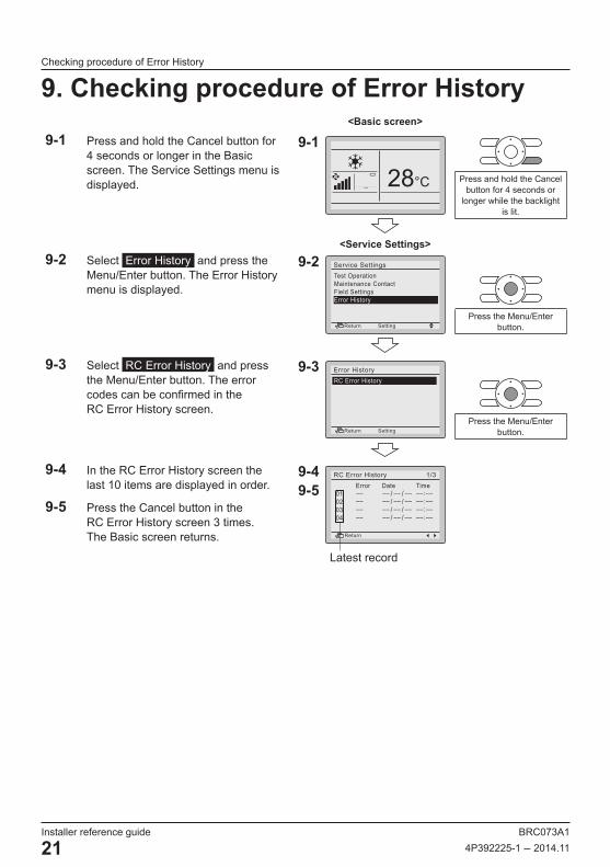
9-1 Press and hold the Cancel button for 4 seconds or longer in the Basic screen. The Service Settings menu is displayed.
9-1
28°C
<Service Settings>
Press and hold the Cancel button for 4 seconds or
longer while the backlight is lit.
9-2 Select Error History and press the Menu/Enter button. The Error History menu is displayed.
9-2Test OperationMaintenance ContactField SettingsError History
Service Settings
SettingReturnPress the Menu/Enter
button.
9-3 Select RC Error History and press the Menu/Enter button. The error codes can be confirmed in the RC Error History screen.
9-3 2/2RC Error HistoryError History
SettingReturnPress the Menu/Enter
button.
9-4 In the RC Error History screen the last 10 items are displayed in order.
9-5 Press the Cancel button in the RC Error History screen 3 times. The Basic screen returns.
9-49-5
1/3 Error Date TimeRC Error History
Return
Latest record
BRC073A1 Installer reference guide4P392225-1 – 2014.11 22
Registration method of the Maintenance Contact information
10. Registration method of the Maintenance Contact information
● Registration of the service contact information.
<Basic screen>
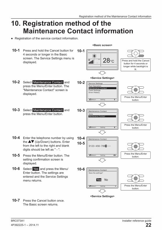
10-1 Press and hold the Cancel button for 4 seconds or longer in the Basic screen. The Service Settings menu is displayed.
10-1
28°C
<Service Settings>
Press and hold the Cancel button for 4 seconds or longer while backlight is
lit.
10-2 Select Maintenance Contact and press the Menu/Enter button. The "Maintenance Contact" screen is displayed.
10-2Test OperationMaintenance ContactField SettingsError History
Service Settings
SettingReturnPress the Menu/Enter
button.
10-3 Select Maintenance Contact and press the Menu/Enter button.
10-3NoneMaintenance Contact
Maintenance Contact
SettingReturnPress the Menu/Enter
button.
10-4 Enter the telephone number by using the (Up/Down) buttons. Enter from the left to the right and blank digits should be left as " - ".
10-5 Press the Menu/Enter button. The setting confirmation screen is displayed.
10-410-5
0123–456–7890–––
Maintenance Contact
SettingReturnPress the Menu/Enter
button.
10-6 Select Yes and press the Menu/Enter button. The settings are entered and the Service Settings menu returns.
10-6
NoYes
Maintenance ContactSave the settings?
SettingReturn
<Service Settings>
Press the Menu/Enter button.
10-7 Press the Cancel button once. The Basic screen returns.
Installer reference guide BRC073A1
23 4P392225-1 – 2014.11
Confirmation of registered details
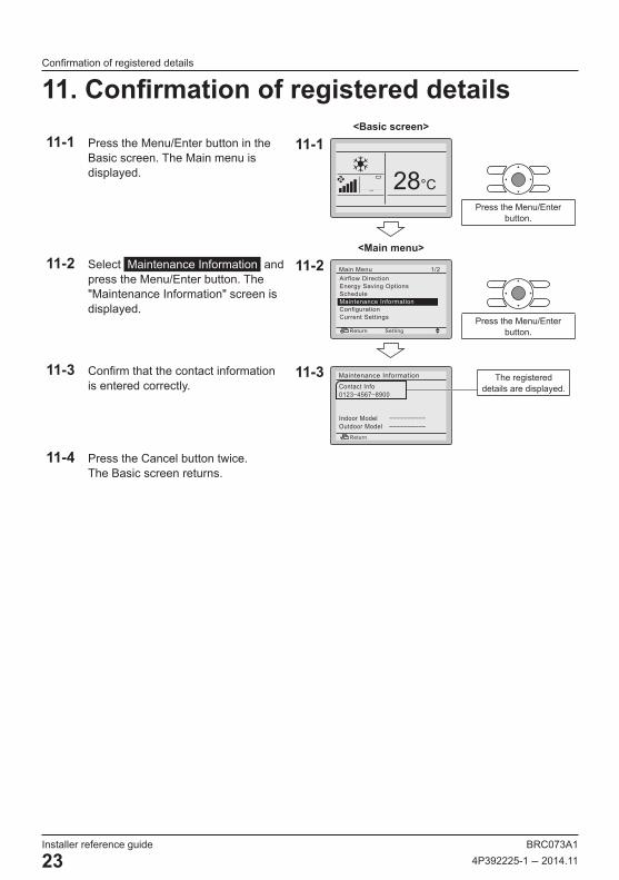
11. Confirmation of registered details<Basic screen>
11-1 Press the Menu/Enter button in the Basic screen. The Main menu is displayed.
11-1
28°C
<Main menu>
Press the Menu/Enter button.
11-2 Select Maintenance Information and press the Menu/Enter button. The "Maintenance Information" screen is displayed.
11-2
SettingReturn
Airflow DirectionEnergy Saving OptionsScheduleMaintenance Information ConfigurationCurrent Settings
1/2Main Menu
Press the Menu/Enter button.
11-3 Confirm that the contact information is entered correctly.
11-3Contact Info0123–4567–8900
Indoor Model ––––––––––Outdoor Model ––––––––––
Maintenance Information
Return
11-4 Press the Cancel button twice. The Basic screen returns.
The registered details are displayed.

BRC073A1 Installer reference guide4P392225-1 – 2014.11 24
Clock & Calendar
12. Clock & Calendar<Basic screen>
12-1 Press the Menu/Enter button in the Basic screen. The Main menu is displayed.
12-1
28°C
<Main menu>
Press the Menu/Enter button.
12-2 Select Clock & Calendar and press the Menu/Enter button. The "Clock & Calendar" menu is displayed.
12-2
SettingReturn
Clock & CalendarLanguage
2/2Main Menu
Press the Menu/Enter button.
12-3 Select Date & Time and press the Menu/Enter button. The "Date & Time" screen is displayed.
12-3Date & Time12H/24H Clock
Clock & Calendar
SettingReturnPress the Menu/Enter
button.
12-4 Select the "Year", "Month", "Day" and time by using the (Left/Right) buttons and change the value by using the (Up/Down) buttons. When the buttons are pressed and held, the values change continuously.
12-5 Press the Menu/Enter button. The confirmation screen is displayed.
12-412-5
0:00Wednesday
1Day1Month2014Year
Setting
Date & Time
Return
The day of the week is set automatically. NOTE
Press the Menu/Enter button.
12-6 Select Yes and press the Menu/Enter button. The settings are confirmed and the Basic screen returns.
12-6
NoYes
Date & TimeSave the settings?
SettingReturn
<Basic screen>
Press the Menu/Enter button.
If a power outage lasts longer than 48 hours, the time is reset and needs to be set again.NOTE
Installer reference guide BRC073A1
25 4P392225-1 – 2014.11
Language
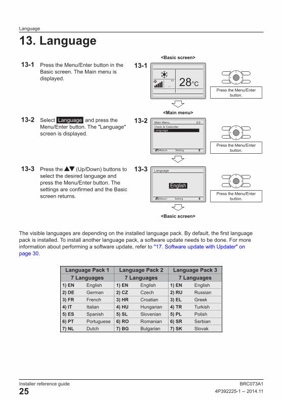
13. Language<Basic screen>
13-1 Press the Menu/Enter button in the Basic screen. The Main menu is displayed.
13-1
28°C
<Main menu>
Press the Menu/Enter button.
13-2 Select Language and press the Menu/Enter button. The "Language" screen is displayed.
13-2
SettingReturn
Clock & CalendarLanguage
2/2Main Menu
Press the Menu/Enter button.
13-3 Press the (Up/Down) buttons to select the desired language and press the Menu/Enter button. The settings are confirmed and the Basic screen returns.
13-3
English
Language
SettingReturn
<Basic screen>
Press the Menu/Enter button.
The visible languages are depending on the installed language pack. By default, the first language pack is installed. To install another language pack, a software update needs to be done. For more information about performing a software update, refer to "17. Software update with Updater" on page 30.
Language Pack 1 Language Pack 2 Language Pack 37 Languages 7 Languages 7 Languages
1) EN English 1) EN English 1) EN English2) DE German 2) CZ Czech 2) RU Russian3) FR French 3) HR Croatian 3) EL Greek4) IT Italian 4) HU Hungarian 4) TR Turkish5) ES Spanish 5) SL Slovenian 5) PL Polish6) PT Portuguese 6) RO Romanian 6) SR Serbian7) NL Dutch 7) BG Bulgarian 7) SK Slovak
BRC073A1 Installer reference guide4P392225-1 – 2014.11 26
Prohibit Buttons
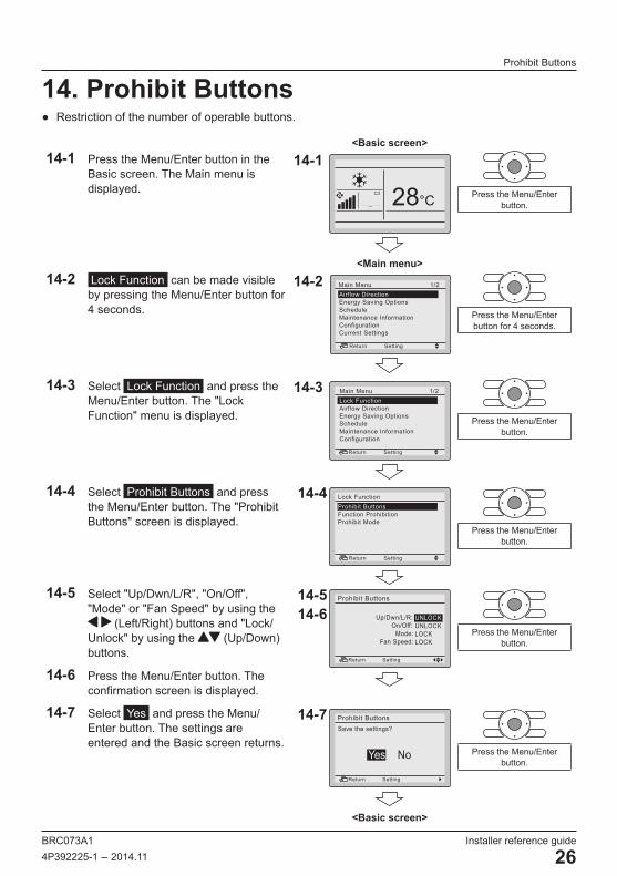
14. Prohibit Buttons ● Restriction of the number of operable buttons.
<Basic screen>14-1 Press the Menu/Enter button in the
Basic screen. The Main menu is displayed.
14-1
28°C
<Main menu>
Press the Menu/Enter button.
14-2 Lock Function can be made visible by pressing the Menu/Enter button for 4 seconds.
14-2
SettingReturn
Airflow DirectionEnergy Saving OptionsScheduleMaintenance InformationConfigurationCurrent Settings
1/2Main Menu
Press the Menu/Enter button for 4 seconds.
14-3 Select Lock Function and press the Menu/Enter button. The "Lock Function" menu is displayed.
14-3
SettingReturn
Lock FunctionAirflow DirectionEnergy Saving OptionsScheduleMaintenance InformationConfiguration
1/2Main Menu
Press the Menu/Enter button.
14-4 Select Prohibit Buttons and press the Menu/Enter button. The "Prohibit Buttons" screen is displayed.
14-4
SettingReturn
Prohibit ButtonsFunction ProhibitionProhibit Mode
Lock Function
Press the Menu/Enter button.
14-5 Select "Up/Dwn/L/R", "On/Off", "Mode" or "Fan Speed" by using the
(Left/Right) buttons and "Lock/Unlock" by using the (Up/Down) buttons.
14-6 Press the Menu/Enter button. The confirmation screen is displayed.
14-514-6 Up/Dwn/L/R:
On/Off: Mode: Fan Speed:
Prohibit Buttons
SettingReturn
UNLOCKUNLOCKLOCKLOCK
Press the Menu/Enter button.
14-7 Select Yes and press the Menu/Enter button. The settings are entered and the Basic screen returns.
14-7
NoYes
Prohibit ButtonsSave the settings?
SettingReturn
<Basic screen>
Press the Menu/Enter button.

Installer reference guide BRC073A1
27 4P392225-1 – 2014.11
Function Prohibition
15. Function Prohibition ● Restriction of the number of operable functions.
<Basic screen>15-1 Press the Menu/Enter button in the
Basic screen. The Main menu is displayed.
15-1
28°C
<Main menu>
Press the Menu/Enter button.
15-2 Lock Function can be made visible by pressing the Menu/Enter button for 4 seconds.
15-2
SettingReturn
Airflow DirectionEnergy Saving OptionsScheduleMaintenance InformationConfigurationCurrent Settings
1/2Main Menu
Press the Menu/Enter button for 4 seconds.
15-3 Select Lock Function and press the Menu/Enter button. The "Lock Function" menu is displayed.
15-3
SettingReturn
Lock FunctionAirflow DirectionEnergy Saving OptionsScheduleMaintenance InformationConfiguration
1/2Main Menu
Press the Menu/Enter button.
15-4 Select Function Prohibition and press the Menu/Enter button. The "Function Prohibition" screen is displayed.
15-4Prohibit ButtonsFunction ProhibitionProhibit Mode
SettingReturn
Lock Function
Press the Menu/Enter button.
15-5 Select the desired function by using the (Left/Right) buttons and "Lock/Unlock" by using the (Up/Down) buttons.
15-6 Press the Menu/Enter button. The confirmation screen is displayed.
15-515-6
SettingReturn
Schedule Configuration
Clock & CalendarEnergy Saving list
Setpoint RangeSetback Condition
:UNLOCK:UNLOCK:UNLOCK:UNLOCK:UNLOCK:UNLOCK
Function Prohibition 1/2
Press the Menu/Enter button.
BRC073A1 Installer reference guide4P392225-1 – 2014.11 28
Prohibit Mode
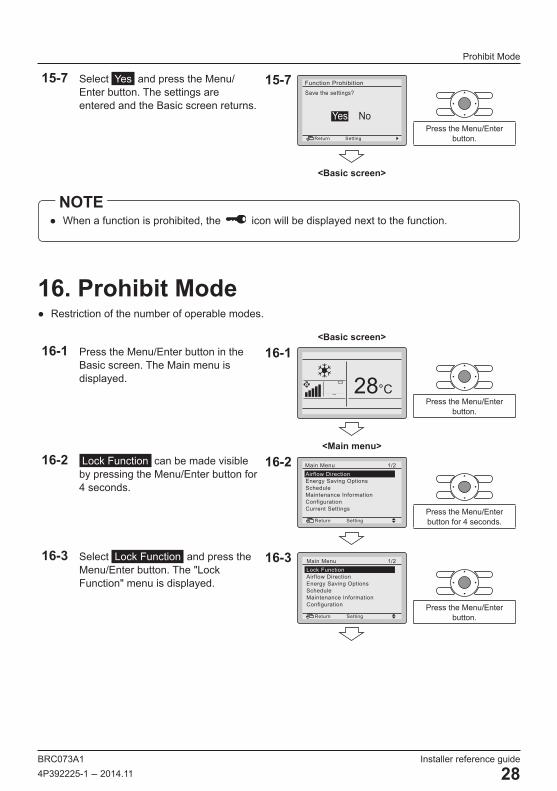
15-7 Select Yes and press the Menu/Enter button. The settings are entered and the Basic screen returns.
15-7
NoYes
Function Prohibition Save the settings?
SettingReturn
<Basic screen>
Press the Menu/Enter button.
● When a function is prohibited, the icon will be displayed next to the function.NOTE
16. Prohibit Mode ● Restriction of the number of operable modes.
<Basic screen>16-1 Press the Menu/Enter button in the
Basic screen. The Main menu is displayed.
16-1
28°C
<Main menu>
Press the Menu/Enter button.
16-2 Lock Function can be made visible by pressing the Menu/Enter button for 4 seconds.
16-2
SettingReturn
Airflow DirectionEnergy Saving OptionsScheduleMaintenance InformationConfigurationCurrent Settings
1/2Main Menu
Press the Menu/Enter button for 4 seconds.
16-3 Select Lock Function and press the Menu/Enter button. The "Lock Function" menu is displayed.
16-3
SettingReturn
Lock FunctionAirflow DirectionEnergy Saving OptionsScheduleMaintenance InformationConfiguration
1/2Main Menu
Press the Menu/Enter button.

Installer reference guide BRC073A1
29 4P392225-1 – 2014.11
Prohibit Mode
16-4 Select Prohibit Mode and press the Menu/Enter button. The "Prohibit Mode" screen is displayed.
16-4
SettingReturn
Prohibit ButtonsFunction ProhibitionProhibit Mode
Lock Function
Press the Menu/Enter button.
16-5 Select “Fan”, “Cool”, “Heat”, “Auto” or “Dry” using the (Left/Right) buttons and “Enable/Disable” the selected mode by using the (Up/ Down) buttons.
16-6 Press the Menu/Enter button. The confirmation screen is displayed.
16-516-6
SettingReturn
FanCoolHeatAutoDry
:Enable:Enable:Enable:Enable:Enable
Prohibit Mode
Press the Menu/Enter button.
16-7 Select Yes and press the Menu/Enter button. The settings are confirmed and the Basic screen returns.
16-7
SettingReturn
Save the settings?Prohibit Mode
NoYes
<Basic screen>
Press the Menu/Enter button.
● When the currently active mode is locked, this mode will still be active upon returning to the Basic screen. Only when the mode is changed, the disabled mode will not be available anymore. When all modes are locked, it is not possible to change to another mode other than the currently active mode.
NOTE
BRC073A1 Installer reference guide4P392225-1 – 2014.11 30
Software update with Updater
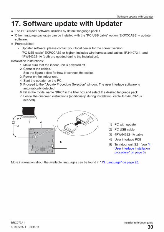
17. Software update with Updater ● The BRC073A1 software includes by default language pack 1. ● Other language packages can be installed with the "PC USB cable" option (EKPCCAB3) + updater
software. ● Prerequisites:
- Updater software: please contact your local dealer for the correct version. - "PC USB cable" EKPCCAB3 or higher: includes wire harness and cables 4P344073-1- and
4PW64322-1A (both are needed during the installation).Installation instructions:
1. Make sure that the indoor unit is powered off.2. Connect the cables.
See the figure below for how to connect the cables.3. Power on the indoor unit.4. Start the updater on the PC.5. Proceed to the "Update Procedure Selection" window. The user interface software is
automatically detected.6. Fill in the model name "BRC" in the filter box and select the desired language pack.7. Follow the onscreen instructions (additionally, during installation, cable 4P344073-1 is
needed).
X1A
13
42
5
1) PC with updater2) PC USB cable3) 4PW64322-1A cable4) User interface PCB5) To indoor unit S21 (see "4.
User interface installation procedure" on page 5)
More information about the available languages can be found in "13. Language" on page 25.

Cop
yrig
ht 2
014
Dai
kin
4P392225-1 2014.11