Embed Size (px)
Citation preview
AC 21-99 Aircraft Wiring and Bonding
Sect 2 Chap 1
1
SECTION 2 CHAPTER 1
WIRE AND CABLE
INTRODUCTION
1. In order to make installation, maintenance, and repair easier, runs of electric wire and cable in aircraft are broken at specified locations by junctions such as connectors, terminal blocks, busses, etc. Before assembly to these junctions, wires and cables must be cut to length, identified, stripped, and if required, tinned.
2. This chapter describes a variety of wire and cables suitable for use in aircraft.
REFERENCE SPECIFICATIONS
3. The following specifications are applicable to aircraft wire and cable preparation:
MIL-C-17 Cable, Radio Frequency, Flexible and Semirigid, General Specification
MIL-C-5756 Cable and Wire Power, Electric, Portable
MIL-C-85485 Cable, Electric, Filter Line, Radio Frequency Absorptive
MIL-DTL-16878 Wire, Electrical, Insulated, General Specification
MIL-DTL-25038 Wire, Electrical, High Temperature and Fire Resistant Aircraft
MIL-DTL-8777 Wire, Electrical Silicone Insulated Copper, 600 Volts, 200C
MIL-W-22759 Wire, Electric, Fluoropolymer Insulated, Copper or Copper Alloy
MIL-W-7072 (Cancelled)
Wire Electric, 600 Volts, Aluminium, Aircraft
NEMA WC 27500 Cable, Electrical, Shielded and Unshielded, Aerospace
SAE AS 81044 Wire, Electric, Crosslinked Polyalkene, Crosslinked Alkane-imide Polymer, or Polyarylene Insulated, Copper or Copper Alloy
MIL-DTL-81381
Wire, Electric, Polyimide Insulated, Copper and Copper Alloy
DEFINITIONS
Insulated Wire
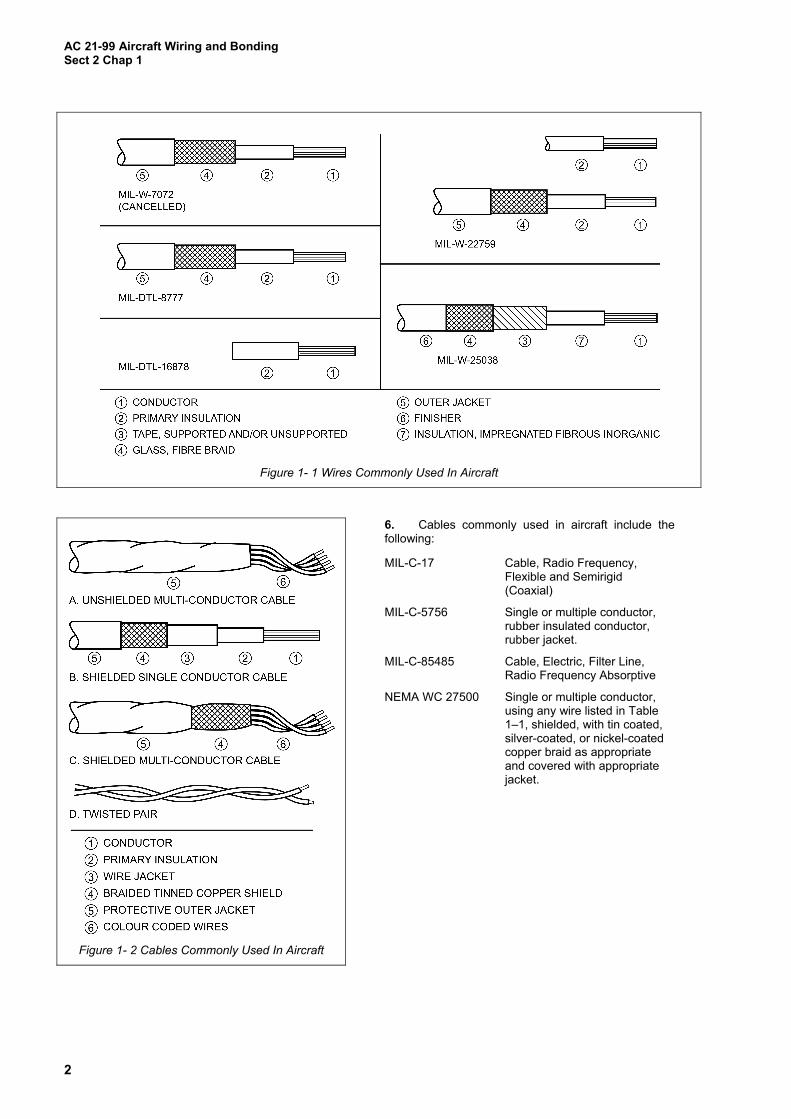
4. For the purposes of electric and electronic installation in aircraft, an insulated wire consists of a metal conductor covered with a dielectric or insulating material (refer to Figure 1–1). Insulated wire is usually referred to as “wire” and will be so designated in this manual. Wires used in aircraft contain stranded conductors for flexibility. Insulations may consist of several materials and layers to provide dielectric insulation, thermal protection, abrasion resistance, moisture resistance, and fluid resistance. Wires commonly used in aircraft are described in Table 1–1. Insulations commonly used in aircraft are described in Table 1–2.
Cable
5. The term “cable,” as used in aircraft electrical installations (refer to Figure 1–2), includes the following:
a. Two or more insulated conductors, contained in a common covering, or twisted together without a common covering (multi-conductor cable).
a. One or more insulated conductors with an overall shield, or with an overall shield and a jacket over the shield (shielded cable).
b. Two insulated conductors twisted together (twisted pair).
c. A single insulated centre conductor with a metallic braided outer conductor (coaxial cable). The concentricity of centre and outer conductor is carefully controlled during manufacture to ensure that they are coaxial.
AC 21-99 Aircraft Wiring and Bonding Sect 2 Chap 1
2
Figure 1- 1 Wires Commonly Used In Aircraft
Figure 1- 2 Cables Commonly Used In Aircraft
6. Cables commonly used in aircraft include the following:
MIL-C-17 Cable, Radio Frequency, Flexible and Semirigid (Coaxial)
MIL-C-5756 Single or multiple conductor, rubber insulated conductor, rubber jacket.
MIL-C-85485 Cable, Electric, Filter Line, Radio Frequency Absorptive
NEMA WC 27500 Single or multiple conductor, using any wire listed in Table 1–1, shielded, with tin coated, silver-coated, or nickel-coated copper braid as appropriate and covered with appropriate jacket.
AC 21-99 Aircraft Wiring and Bonding
Sect 2 Chap 1
3
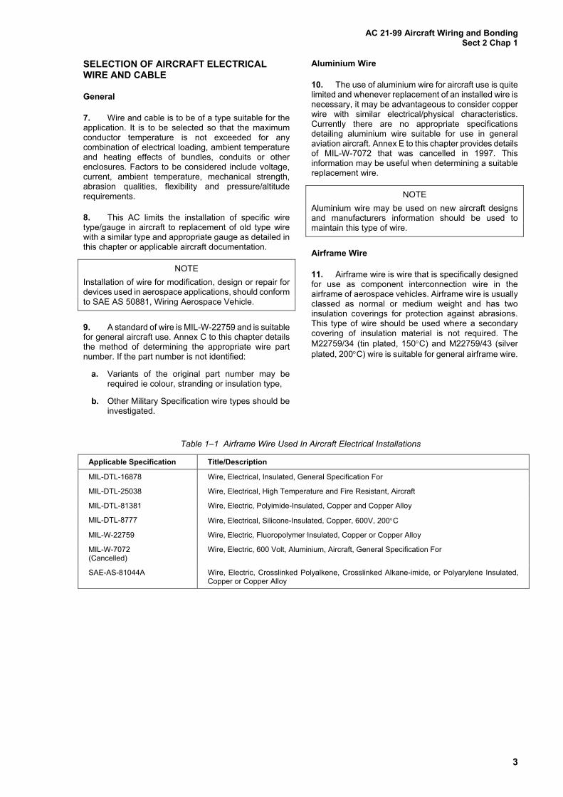
SELECTION OF AIRCRAFT ELECTRICAL WIRE AND CABLE
General
7. Wire and cable is to be of a type suitable for the application. It is to be selected so that the maximum conductor temperature is not exceeded for any combination of electrical loading, ambient temperature and heating effects of bundles, conduits or other enclosures. Factors to be considered include voltage, current, ambient temperature, mechanical strength, abrasion qualities, flexibility and pressure/altitude requirements.
8. This AC limits the installation of specific wire type/gauge in aircraft to replacement of old type wire with a similar type and appropriate gauge as detailed in this chapter or applicable aircraft documentation.
NOTE
Installation of wire for modification, design or repair for devices used in aerospace applications, should conform to SAE AS 50881, Wiring Aerospace Vehicle.
9. A standard of wire is MIL-W-22759 and is suitable for general aircraft use. Annex C to this chapter details the method of determining the appropriate wire part number. If the part number is not identified:
a. Variants of the original part number may be required ie colour, stranding or insulation type,
b. Other Military Specification wire types should be investigated.
Aluminium Wire
10. The use of aluminium wire for aircraft use is quite limited and whenever replacement of an installed wire is necessary, it may be advantageous to consider copper wire with similar electrical/physical characteristics. Currently there are no appropriate specifications detailing aluminium wire suitable for use in general aviation aircraft. Annex E to this chapter provides details of MIL-W-7072 that was cancelled in 1997. This information may be useful when determining a suitable replacement wire.
NOTE
Aluminium wire may be used on new aircraft designs and manufacturers information should be used to maintain this type of wire.
Airframe Wire
11. Airframe wire is wire that is specifically designed for use as component interconnection wire in the airframe of aerospace vehicles. Airframe wire is usually classed as normal or medium weight and has two insulation coverings for protection against abrasions. This type of wire should be used where a secondary covering of insulation material is not required. The M22759/34 (tin plated, 150C) and M22759/43 (silver plated, 200C) wire is suitable for general airframe wire.
Table 1–1 Airframe Wire Used In Aircraft Electrical Installations
Applicable Specification Title/Description
MIL-DTL-16878 Wire, Electrical, Insulated, General Specification For
MIL-DTL-25038 Wire, Electrical, High Temperature and Fire Resistant, Aircraft
MIL-DTL-81381 Wire, Electric, Polyimide-Insulated, Copper and Copper Alloy
MIL-DTL-8777 Wire, Electrical, Silicone-Insulated, Copper, 600V, 200C
MIL-W-22759 Wire, Electric, Fluoropolymer Insulated, Copper or Copper Alloy
MIL-W-7072 (Cancelled)
Wire, Electric, 600 Volt, Aluminium, Aircraft, General Specification For
SAE-AS-81044A Wire, Electric, Crosslinked Polyalkene, Crosslinked Alkane-imide, or Polyarylene Insulated, Copper or Copper Alloy
AC 21-99 Aircraft Wiring and Bonding Sect 2 Chap 1
4
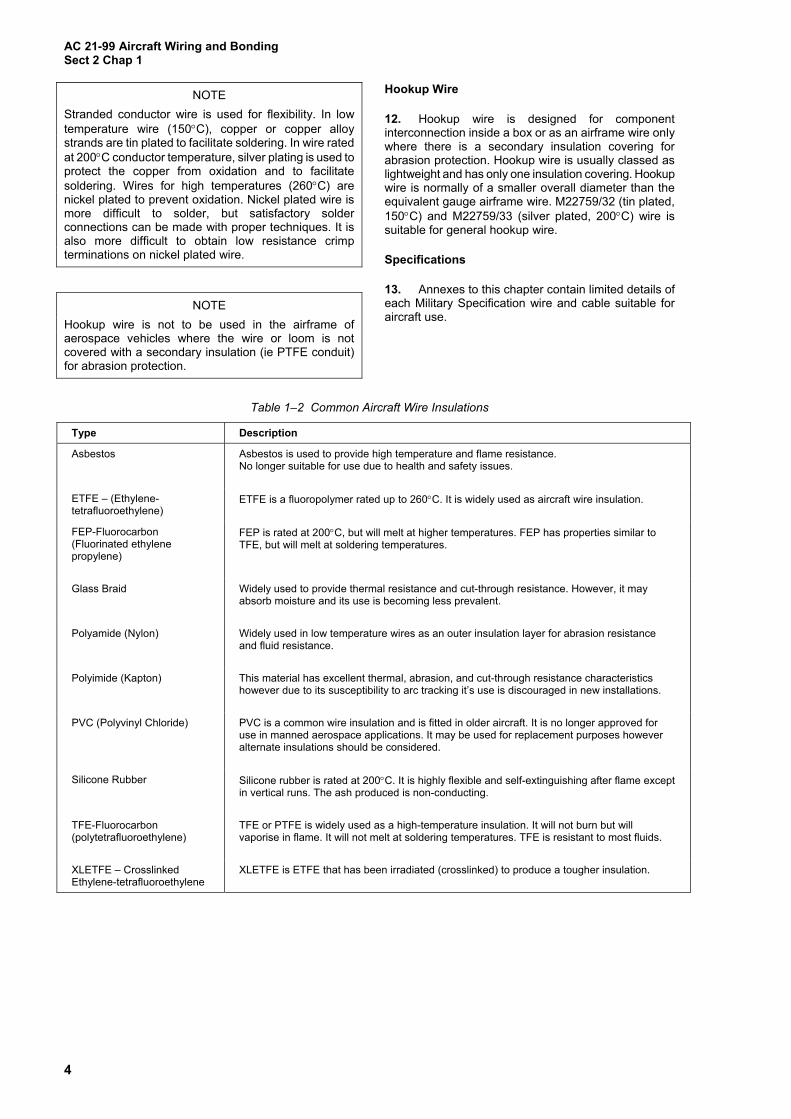
NOTE
Stranded conductor wire is used for flexibility. In low temperature wire (150C), copper or copper alloy strands are tin plated to facilitate soldering. In wire rated at 200C conductor temperature, silver plating is used to protect the copper from oxidation and to facilitate soldering. Wires for high temperatures (260C) are nickel plated to prevent oxidation. Nickel plated wire is more difficult to solder, but satisfactory solder connections can be made with proper techniques. It is also more difficult to obtain low resistance crimp terminations on nickel plated wire.
NOTE
Hookup wire is not to be used in the airframe of aerospace vehicles where the wire or loom is not covered with a secondary insulation (ie PTFE conduit) for abrasion protection.
Hookup Wire
12. Hookup wire is designed for component interconnection inside a box or as an airframe wire only where there is a secondary insulation covering for abrasion protection. Hookup wire is usually classed as lightweight and has only one insulation covering. Hookup wire is normally of a smaller overall diameter than the equivalent gauge airframe wire. M22759/32 (tin plated, 150C) and M22759/33 (silver plated, 200C) wire is suitable for general hookup wire.
Specifications
13. Annexes to this chapter contain limited details of each Military Specification wire and cable suitable for aircraft use.
Table 1–2 Common Aircraft Wire Insulations
Type Description
Asbestos Asbestos is used to provide high temperature and flame resistance. No longer suitable for use due to health and safety issues.
ETFE – (Ethylene-tetrafluoroethylene)
ETFE is a fluoropolymer rated up to 260C. It is widely used as aircraft wire insulation.
FEP-Fluorocarbon (Fluorinated ethylene propylene)
FEP is rated at 200C, but will melt at higher temperatures. FEP has properties similar to TFE, but will melt at soldering temperatures.
Glass Braid Widely used to provide thermal resistance and cut-through resistance. However, it may absorb moisture and its use is becoming less prevalent.
Polyamide (Nylon) Widely used in low temperature wires as an outer insulation layer for abrasion resistance and fluid resistance.
Polyimide (Kapton) This material has excellent thermal, abrasion, and cut-through resistance characteristics however due to its susceptibility to arc tracking it’s use is discouraged in new installations.
PVC (Polyvinyl Chloride) PVC is a common wire insulation and is fitted in older aircraft. It is no longer approved for use in manned aerospace applications. It may be used for replacement purposes however alternate insulations should be considered.
Silicone Rubber Silicone rubber is rated at 200C. It is highly flexible and self-extinguishing after flame except in vertical runs. The ash produced is non-conducting.
TFE-Fluorocarbon (polytetrafluoroethylene)
TFE or PTFE is widely used as a high-temperature insulation. It will not burn but will vaporise in flame. It will not melt at soldering temperatures. TFE is resistant to most fluids.
XLETFE – Crosslinked Ethylene-tetrafluoroethylene
XLETFE is ETFE that has been irradiated (crosslinked) to produce a tougher insulation.

AC 21-99 Aircraft Wiring and Bonding
Sect 2 Chap 1
5
Limitations
14. Insulation. Except for existing installations, the use of polyvinyl chloride (PVC) insulated wire and cable for manned aerospace applications is prohibited.
15. Kapton. Due to the undesirable properties exhibited by polyimide (Kapton) insulated wiring, its use in aircraft should be avoided wherever practicable.
Wire Temperature Ratings
16. Generally, aircraft electrical wire must be selected to perform continuously in a specified temperature range ie 150C, 200C, 260C or fire resistant. Degradation will occur if the wire is subjected to continuous operation at elevated temperatures. Factors to be considered that will affect the temperature are:
a. Wire Gauge. The wire should be of a gauge to ensure adequate current carrying capacity so that the voltage drops are acceptable.
b. Current Carrying Capacity. The continuous duty current for each wire gauge is specified in Annex I to this chapter.
c. Bundle/Looms or Conduit. Annex I to this chapter details current ratings for the following:
(1) wires positioned in free air, and
(2) wires in bundles, conduit or confined areas.
NOTE
The ratings listed in Annex I are based upon bundles of 33 or more wires. For further information on current ratings, refer to SAE AS 50881 or contact the publication sponsor.
d. Aluminium Wire. The use of aluminium wire shall be restricted in applications and should not be:
(1) directly attached to engine mounted accessories or any area of severe vibration, or
e. installed where frequent connection/disconnection is necessary.
f. Aluminium Terminations. Aluminium terminations should conform to SAE AS 70991. Refer to Section 2, Chapter 6 of this publication for details of aluminium terminals.
g. Minimum Wire Size. The minimum wire sizes are specified below unless authorised by specific aircraft publications.
(1) Copper Wire. SAE AS 50881 prohibits the use of wires smaller than 22 AWG for use in aircraft, helicopters and lighter than air vehicles. This restriction is due to maintenance difficulties, however many service aircraft have now been manufactured using 24 AWG and 26 AWG wire. When required, these wires should be repaired/replaced with similar gauge wires. Appropriate precautions should be taken to prevent failure caused by vibration and handling and wires should be adequately supported at each termination. For direct attachment to engine mounted accessories, wire size smaller than 18 AWG should not normally be used, however where 20 AWG wires are required they may be used, provided they are grouped, spot tied and clamped to the connector. If fewer than four 20 AWG wires are used with one connector, insulated tubing is to be used.
(2) Aluminium Wire Size. Aluminium wire is restricted to 8 AWG minimum. (Refer to para 10).
h. Maximum Wire Size. The maximum wire sizes should be as listed below, unless specifically authorised by the applicable aircraft documentation.
(1) Copper wire - 2 AWG.
(2) Aluminium wire - 0 AWG.

AC 21-99 Aircraft Wiring and Bonding Sect 2 Chap 1
6
Annexes:
A. MIL-DTL-16878 Wire, Electrical, Insulated, General Specification
B. SAE-AS-81044 Wire, Electrical, Crosslinked Polyalkene, Crosslinked Alkane-imide Polymer or Polyarylene Insulated Copper or Copper Alloy
C. MIL-W-22759 Wire, Electric Fluoropolymer Insulated Copper or Copper Alloy
D. MIL-DTL-25038 Wire, Electrical, High Temperature, Fire Resistant and Flight Critical, General Specification
E. MIL-W-7072 Wire, Electric, 600 Volt, Aluminium, Aircraft, General Specification
F. NEMA WC 27500 Standard For Aerospace and Industrial Electrical Cable
G. MIL-DTL-81381 Wire, Electric, Polyimide-Insulated, Copper
H. MIL-C-85485 Cable, Electric, Filter Line, Radio Frequency Absorptive
I. Current Ratings of Wire and Maximum Allowable Nicked or Broken Strands
J. Wire Gauge Comparison

AC 21-99 Aircraft Wiring and Bonding
Annex A to Sect 2 Chap 1
1A–1
MIL-DTL-16878 WIRE, ELECTRICAL, INSULATED, GENERAL SPECIFICATION
Scope
1. This specification covers unshielded wire for hook-up and lead wiring of electrical and electronic components and equipment. The temperature rating of wire under this specification ranges from -65C to 260C, with potential rating from 250Vrms to 5000Vrms.
Specification Sheets
2. Specification Sheets are as follows:
Table 1-A-1 Specification Sheets
Description MIL-W-16878D MIL-W-16878E MIL-W-16878F MIL-DTL-16878G
600 Volt,105C, PVC TYPE B M16878/1 M16878/17
M16878/1 M16878/17
M16878/1 M16878/17
1000 Volt,105C, PVC TYPE C M16878/2 M16878/18
M16878/2 M16878/18
M16878/2 M16878/18
3000 Volt,105C, PVC TYPE D M16878/3 M16878/19
M16878/3 M16878/19
M16878/3 M16878/19
600 Volt, 200C/260C, PTFE
TYPE E M16878/4 M16878/21 M16878/25 M16878/26
M16878/4 M16878/21 M16878/25 M16878/26
NEMA HP 3 NEMA HP 3 NEMA HP 3 NEMA HP 3
1000 Volt, 200C/260C, PTFE
TYPE EE M16878/5 M16878/22 M16878/27 M16878/28 M16878/34 M16878/35
M16878/5 M16878/22 M16878/27 M16878/28 M16878/34 M16878/35
NEMA HP 3 NEMA HP 3 NEMA HP 3 NEMA HP 3 NEMA HP 3 NEMA HP 3
250 Volt, 200C/260C, PTFE
TYPE ET M16878/6 M16878/20 M16878/23 M16878/24
M16878/6 M16878/20 M16878/23 M16878/24
NEMA HP 3 NEMA HP 3 NEMA HP 3 NEMA HP 3
600 Volt, Silicone Rubber TYPE F M16878/7 M16878/29
M16878/7 M16878/29
M16878/7 M16878/29
1000 Volt, Silicone Rubber TYPE FF M16878/8 M16878/30 M16878/31 M16878/32
M16878/8 M16878/30 M16878/31 M16878/32
M16878/8 M16878/30 M16878/31 M16878/32
PE, 75C TYPE J M16878/10 M16878/33
M16878/10 M16878/33
M16878/10 M16878/33
FEP, 600 Volt, 200C TYPE K M16878/11 M16878/11 NEMA HP 4
FEP, 1000 Volt, 200C TYPE KK M16878/12 M16878/12 NEMA HP 4
FEP, 250 Volt, 200C TYPE KT M16878/13 M16878/13 NEMA HP 4
XLPE, 600 Volt, 125C - - - M16878/14 M16878/14 M16878/14
XLPE, 1000 Volt, 125C - - - M16878/15 M16878/15 M16878/15
XLPE, 3000 Volt, 125C - - - M16878/16 M16878/16 M16878/16
XLPO, 600 Volt, 105C - - - - - - M16878/36 M16878/36

AC 21-99 Aircraft Wiring and Bonding Annex A to Sect 2 Chap 1
1A–2
Table 1-A-1 Specification Sheets (continued)
Description MIL-W-16878D MIL-W-16878E MIL-W-16878F MIL-DTL-16878G
EPDM, 600 Volt, 125C - - - - - - M16878/37 M16878/37
EPDM, 5000 Volt, 125C - - - - - - M16878/38 M16878/38
NATIONAL ELECTRICAL MANUFACTURERS ASSOCIATION (NEMA)
NEMA HP 3 - Electrical and Electronic PTFE Insulated High Temperature Hook-Up Wire; Types ET (250 Volts), E (600 Volts) and EE (1000 Volts)
NEMA HP 4 - Electrical and Electronic FEP Insulated High Temperature Hook-Up Wire; Types KT (250 Volts), K (600 Volts) and KK (1000 Volts).
Part Number
3. Part numbers under this specification are coded as in the following example:
Table 1-A-2 Part Number Coding
M16878/3 B C B 903
Specification Sheet (para 2)
Conductor Material (para 4)
Conductor Size (para 5)
Conductor Stranding (para 6)
Insulation Colour Code (para 7)
Conductor Material
4. Conductor Material is designated by a single letter as follows:
B – Coated Copper
C – Coated Copper-Clad Steel
D – Coated High Strength Copper Alloy
Conductor Size
5. The conductor American Wire Gauge (AWG) size is designated by a single letter as follows:
Table 1-A-3 Conductor Size
AWG Letter AWG Letter
32 30 28 26 24 22 20 18 16 14 12
A B C D E F G H J K L
10 8 6 4 2 1 0
00 000
0000
M N P R S T U W Y Z

AC 21-99 Aircraft Wiring and Bonding
Annex A to Sect 2 Chap 1
1A–3
Conductor Stranding
6. The number of strands making up the conductor is designated by a single letter as follows:
Table 1-A-4 Conductor Stranding
Number of Strands Letter Number of Strands Letter
1 7
10 16 19 26 37 41 65
105
A B C D E F G H J K
133 259 427 665 817
1045 1330 1672 2109
L M M P R S T V W
Insulation Colour Code
7. The insulation colour code is in accordance with the identification coding of MIL-STD-681 and may be one, two, or three digits depending on the number of stripes or bands. The first number is the colour of the insulation; the second number is the colour of the first stripe or band; and the third number is the colour of the second stripe or band. The colours and their corresponding numbers are as follows:
Table 1-A-5 Colour Code
Colour Number Designator Colour Number Designator
Black 0 Green 5
Brown 1 Blue 6
Red 2 Violet (Purple) 7
Orange 3 Grey (Slate) 8
Yellow 4 White 9

AC 21-99 Aircraft Wiring and Bonding Annex A to Sect 2 Chap 1
1A–4
Blank Page
AC 21-99 Aircraft Wiring and Bonding
Annex B to Sect 2 Chap 1
1B–1
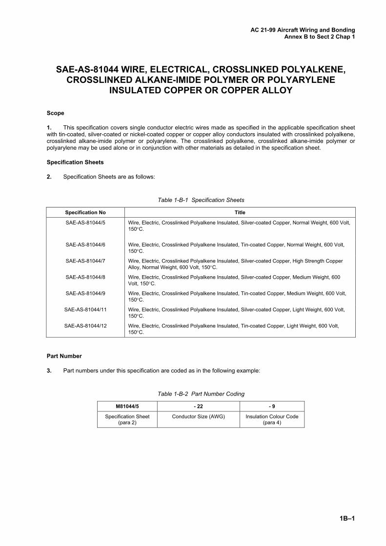
SAE-AS-81044 WIRE, ELECTRICAL, CROSSLINKED POLYALKENE, CROSSLINKED ALKANE-IMIDE POLYMER OR POLYARYLENE
INSULATED COPPER OR COPPER ALLOY
Scope
1. This specification covers single conductor electric wires made as specified in the applicable specification sheet with tin-coated, silver-coated or nickel-coated copper or copper alloy conductors insulated with crosslinked polyalkene, crosslinked alkane-imide polymer or polyarylene. The crosslinked polyalkene, crosslinked alkane-imide polymer or polyarylene may be used alone or in conjunction with other materials as detailed in the specification sheet.
Specification Sheets
2. Specification Sheets are as follows:
Table 1-B-1 Specification Sheets
Specification No Title
SAE-AS-81044/5 Wire, Electric, Crosslinked Polyalkene Insulated, Silver-coated Copper, Normal Weight, 600 Volt, 150C.
SAE-AS-81044/6 Wire, Electric, Crosslinked Polyalkene Insulated, Tin-coated Copper, Normal Weight, 600 Volt, 150C.
SAE-AS-81044/7 Wire, Electric, Crosslinked Polyalkene Insulated, Silver-coated Copper, High Strength Copper Alloy, Normal Weight, 600 Volt, 150C.
SAE-AS-81044/8 Wire, Electric, Crosslinked Polyalkene Insulated, Silver-coated Copper, Medium Weight, 600 Volt, 150C.
SAE-AS-81044/9 Wire, Electric, Crosslinked Polyalkene Insulated, Tin-coated Copper, Medium Weight, 600 Volt, 150C.
SAE-AS-81044/11 Wire, Electric, Crosslinked Polyalkene Insulated, Silver-coated Copper, Light Weight, 600 Volt, 150C.
SAE-AS-81044/12 Wire, Electric, Crosslinked Polyalkene Insulated, Tin-coated Copper, Light Weight, 600 Volt, 150C.
Part Number
3. Part numbers under this specification are coded as in the following example:
Table 1-B-2 Part Number Coding
M81044/5 - 22 - 9
Specification Sheet (para 2)
Conductor Size (AWG) Insulation Colour Code (para 4)
AC 21-99 Aircraft Wiring and Bonding Annex B to Sect 2 Chap 1
1B–2
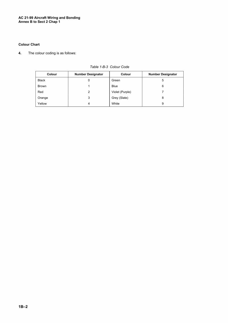
Colour Chart
4. The colour coding is as follows:
Table 1-B-3 Colour Code
Colour Number Designator Colour Number Designator
Black 0 Green 5
Brown 1 Blue 6
Red 2 Violet (Purple) 7
Orange 3 Grey (Slate) 8
Yellow 4 White 9

AC 21-99 Aircraft Wiring and Bonding
Annex C to Sect 2 Chap 1
1C–1
MIL-W-22759 WIRE, ELECTRIC FLUOROPOLYMER-INSULATED COPPER OR COPPER ALLOY
Scope
1. This specification covers fluoropolymer-insulated single conductor electric wires made with tin coated, silver coated or nickel-coated conductors of copper or copper alloy as specified in the applicable specification sheet. The fluoropolymer insulation of these wires may be polytetrafluoroethylene (TFE), fluorinated ethylene propylene (FEP), polyvinylidene fluoride (PVF2), ethylene-tetrafluoroethylene copolymer (ETFE), or other fluoropolymer resin. The fluoropolymer may be used alone or in combination with other insulation materials.
Specification Sheets
2. Specification Sheets are as follows:
Table 1-C-1 Specification Sheets
Specification No Title
MIL-W-22759/1 Wire, Electric, Fluoropolymer-insulated, TFE and TFE Coated Glass, Silver Coated Copper Conductor, 600 Volt, 200°C.
MIL-W-22759/2 Wire, Electric, Fluoropolymer-insulated, TFE and TFE-Coated Glass, Nickel Coated Copper Conductor, 600 Volt, 260°C.
MIL-W-22759/5 Wire, Electric, Fluoropolymer-insulated, Abrasion Resistant, Extruded TFE, Silver Coated Copper Conductor, 600 Volt, 200°C.
MIL-W-22759/7 Wire, Electric, Fluoropolymer-insulated, Abrasion Resistant, Extruded TFE, Medium Weight, Silver Coated Copper Conductor, 600 Volt, 200°C.
MIL-W-22759/8 Wire, Electric, Fluoropolymer-insulated, Abrasion Resistant, Extruded TFE, Medium Weight, Nickel Coated Copper Conductor, 600 Volt, 260°C.
MIL-W-22759/11 Wire, Electric, Fluoropolymer-insulated, Extruded TFE, Silver Coated Copper Conductor, 600 Volt, 200°C.
MIL-W-22759/12 Wire, Electric , Fluoropolymer-insulated, Extruded TFE, Nickel Coated Copper Conductor, 600 Volt, 260°C.
MIL-W-22759/16 Wire, Electric, Fluoropolymer-insulated, Extruded TFE, Medium Weight, Tin Coated Copper Conductor, 600 Volt, 150°C.
MIL-W-22759/22 Wire, Electric, Fluoropolymer-insulated, Extruded TFE, Silver Coated, High Strength, Copper Alloy Conductor, 600 Volt, 200°C.
MIL-W-22759/32 Wire, Electric, Fluoropolymer-insulated, Cross-Linked Modified ETFE, Light Weight, Tin Coated Copper Conductor, 600 Volt, 150°C.
MIL-W-22759/33 Wire, Electric, Fluoropolymer-insulated, Cross-Linked Modified ETFE, Light Weight, Silver Coated, High Strength, Copper Alloy Conductor, 600 Volt, 200°C.
MIL-W-22759/34 Wire, Electric, Fluoropolymer-insulated, Cross-Linked Modified ETFE, Normal Weight, Tin Coated Copper Conductor, 600 Volt, 150°C.
MIL-W-22759/41 Wire, Electric, Fluoropolymer-insulated, Cross-Linked Modified ETFE, Normal Weight, Nickel Coated Copper Conductor, 600 Volt, 200°C.
MIL-W-22759/43 Wire, Electric, Fluoropolymer-insulated, Cross-Linked Modified ETFE, Normal Weight, Silver-Coated Copper Conductor, 600 Volt, 200°C.

AC 21-99 Aircraft Wiring and Bonding Annex C to Sect 2 Chap 1
1C–2
Part Number
3. Part numbers under this specification are coded as in the following example:
Table 1-C-2 Part Number Coding
M22759/1 - 22 - 9
Specification Sheet (para 2)
Wire Size (AWG)
Insulation Colour Code (para 4)
Colour Chart
4. The colour coding is as follows:
Table 1-C-3 Colour Code
Colour Number Designator Colour Number Designator
Black 0 Green 5
Brown 1 Blue 6
Red 2 Violet (Purple) 7
Orange 3 Grey (Slate) 8
Yellow 4 White 9
AC 21-99 Aircraft Wiring and Bonding
Annex D to Sect 2 Chap 1
1D–1
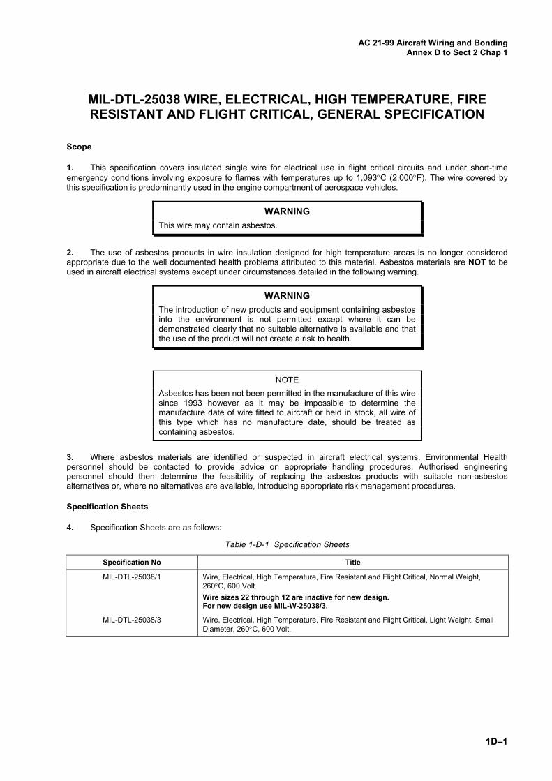
MIL-DTL-25038 WIRE, ELECTRICAL, HIGH TEMPERATURE, FIRE RESISTANT AND FLIGHT CRITICAL, GENERAL SPECIFICATION
Scope
1. This specification covers insulated single wire for electrical use in flight critical circuits and under short-time emergency conditions involving exposure to flames with temperatures up to 1,093C (2,000F). The wire covered by this specification is predominantly used in the engine compartment of aerospace vehicles.
WARNING This wire may contain asbestos.
2. The use of asbestos products in wire insulation designed for high temperature areas is no longer considered appropriate due to the well documented health problems attributed to this material. Asbestos materials are NOT to be used in aircraft electrical systems except under circumstances detailed in the following warning.
WARNING The introduction of new products and equipment containing asbestos into the environment is not permitted except where it can be demonstrated clearly that no suitable alternative is available and that the use of the product will not create a risk to health.
NOTE
Asbestos has been not been permitted in the manufacture of this wire since 1993 however as it may be impossible to determine the manufacture date of wire fitted to aircraft or held in stock, all wire of this type which has no manufacture date, should be treated as containing asbestos.
3. Where asbestos materials are identified or suspected in aircraft electrical systems, Environmental Health personnel should be contacted to provide advice on appropriate handling procedures. Authorised engineering personnel should then determine the feasibility of replacing the asbestos products with suitable non-asbestos alternatives or, where no alternatives are available, introducing appropriate risk management procedures.
Specification Sheets
4. Specification Sheets are as follows:
Table 1-D-1 Specification Sheets
Specification No Title
MIL-DTL-25038/1 Wire, Electrical, High Temperature, Fire Resistant and Flight Critical, Normal Weight, 260C, 600 Volt.
Wire sizes 22 through 12 are inactive for new design. For new design use MIL-W-25038/3.
MIL-DTL-25038/3 Wire, Electrical, High Temperature, Fire Resistant and Flight Critical, Light Weight, Small Diameter, 260C, 600 Volt.

AC 21-99 Aircraft Wiring and Bonding Annex D to Sect 2 Chap 1
1D–2
Part Number
5. Part numbers under this specification are coded as in the following example:
Table 1-D-2 Part Number Coding
M25038/3 - 22 - 9
Specification Sheet (para 2) Wire Size (AWG)
Insulation Colour Code (para 4)
Note: For M25038/3, add ‘H’ to the part number for heavier wall construction.
Colour Chart
6. The colour coding is as follows:
Table 1-D-3 Colour Code
Colour Number Designator
Colour Number Designator
Black 0 Green 5
Brown 1 Blue 6
Red 2 Violet (Purple) 7
Orange 3 Grey (Slate) 8
Yellow 4 White 9

AC 21-99 Aircraft Wiring and Bonding
Annex E to Sect 2 Chap 1
1E–1
MIL-W-7072 WIRE, ELECTRIC, 600 VOLT, ALUMINIUM, AIRCRAFT, GENERAL SPECIFICATION
(CANCELLED)
Scope
1. This specification covers 600 volt insulated single aluminium conductors capable of continuous operation at a maximum conductor temperature of 105C (221F). This wire is suitable for use in aircraft using any combination of electrical loading and ambient temperatures providing that the maximum conductor temperature is not exceeded.
NOTE
This specification and specification sheet were cancelled without replacement in May 1997 and September 1996 respectively. The details below are retained for information purposes only and may be useful when selecting replacement copper wire.
Specification Sheet
2. Specification Sheet is as follows:
Table 1-E-1 Specification Sheet
Specification No Title
MS25191 Wire, Electric, 600 Volt, Aluminium, Aircraft
Part Number
3. Part numbers under this specification are coded as in the following example:
Table 1-E-2 Part Number Coding
M25191 - 01 B
Specification Sheet (para 2)
Wire Size (para 4) Insulation Material (para 5)
AC 21-99 Aircraft Wiring and Bonding Annex E to Sect 2 Chap 1
1E–2
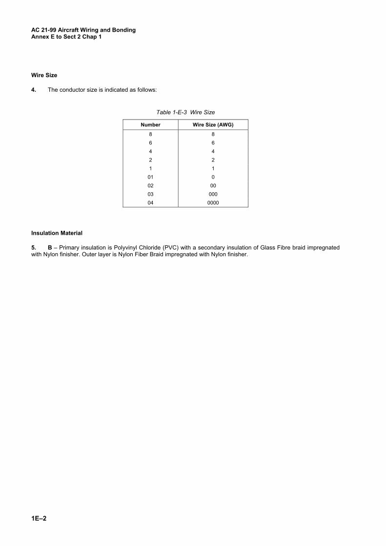
Wire Size
4. The conductor size is indicated as follows:
Table 1-E-3 Wire Size
Number Wire Size (AWG)
8 8
6 6
4 4
2 2
1 1
01 0
02 00
03 000
04 0000
Insulation Material
5. B – Primary insulation is Polyvinyl Chloride (PVC) with a secondary insulation of Glass Fibre braid impregnated with Nylon finisher. Outer layer is Nylon Fiber Braid impregnated with Nylon finisher.
AC 21-99 Aircraft Wiring and Bonding
Annex F to Sect 2 Chap 1
1F–1
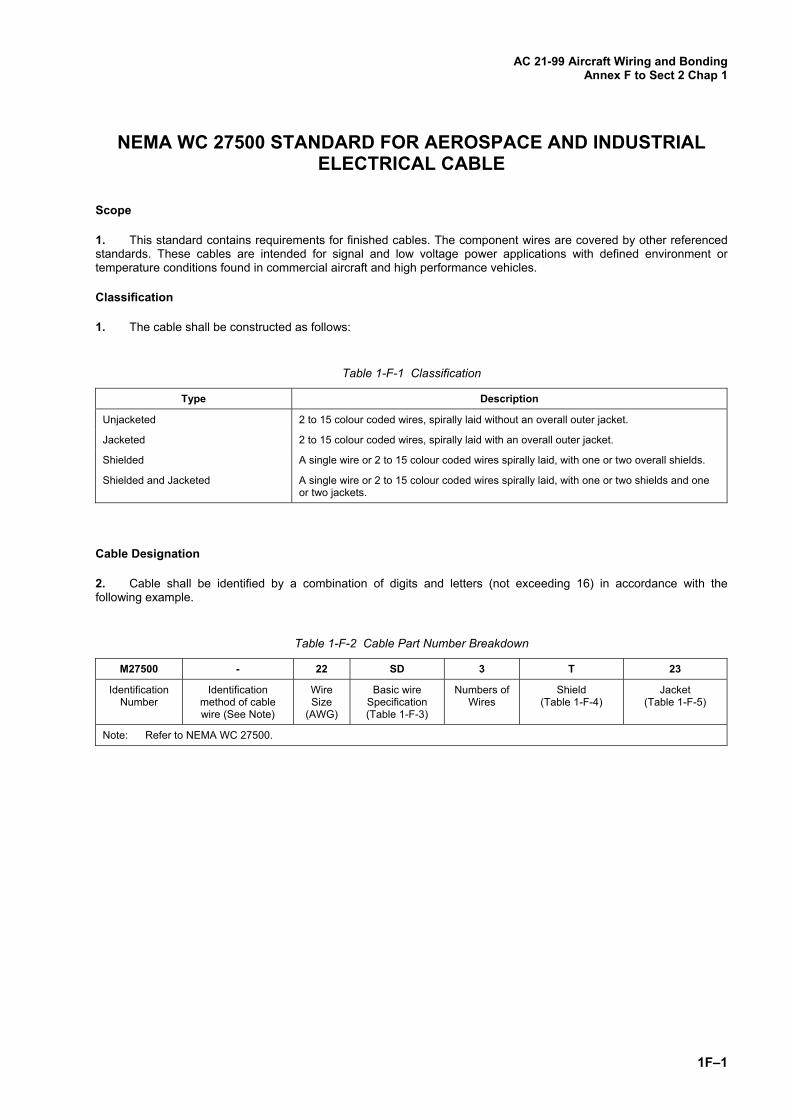
NEMA WC 27500 STANDARD FOR AEROSPACE AND INDUSTRIAL ELECTRICAL CABLE
Scope
1. This standard contains requirements for finished cables. The component wires are covered by other referenced standards. These cables are intended for signal and low voltage power applications with defined environment or temperature conditions found in commercial aircraft and high performance vehicles.
Classification
1. The cable shall be constructed as follows:
Table 1-F-1 Classification
Type Description
Unjacketed 2 to 15 colour coded wires, spirally laid without an overall outer jacket.
Jacketed 2 to 15 colour coded wires, spirally laid with an overall outer jacket.
Shielded A single wire or 2 to 15 colour coded wires spirally laid, with one or two overall shields.
Shielded and Jacketed A single wire or 2 to 15 colour coded wires spirally laid, with one or two shields and one or two jackets.
Cable Designation
2. Cable shall be identified by a combination of digits and letters (not exceeding 16) in accordance with the following example.
Table 1-F-2 Cable Part Number Breakdown
M27500 - 22 SD 3 T 23
Identification Number
Identification method of cable wire (See Note)
Wire Size
(AWG)
Basic wire Specification (Table 1-F-3)
Numbers of Wires
Shield (Table 1-F-4)
Jacket (Table 1-F-5)
Note: Refer to NEMA WC 27500.
AC 21-99 Aircraft Wiring and Bonding Annex F to Sect 2 Chap 1
1F–2
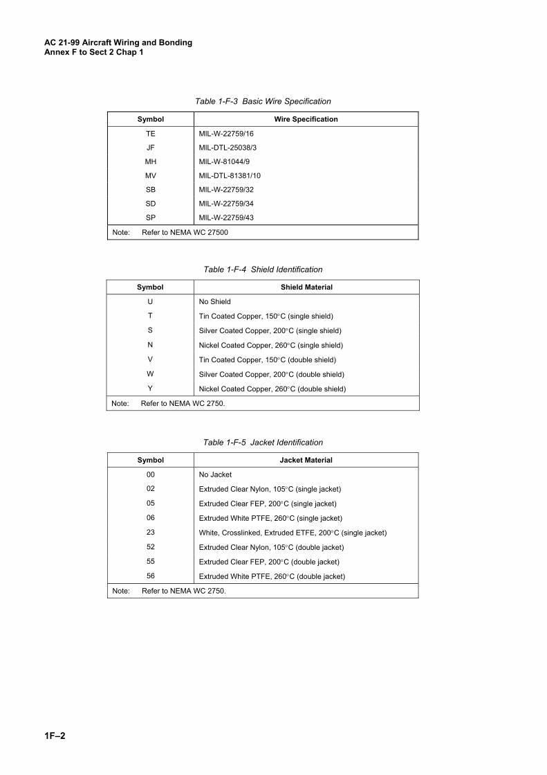
Table 1-F-3 Basic Wire Specification
Symbol Wire Specification
TE MIL-W-22759/16
JF MIL-DTL-25038/3
MH MIL-W-81044/9
MV MIL-DTL-81381/10
SB MIL-W-22759/32
SD MIL-W-22759/34
SP MIL-W-22759/43
Note: Refer to NEMA WC 27500
Table 1-F-4 Shield Identification
Symbol Shield Material
U No Shield
T Tin Coated Copper, 150C (single shield)
S Silver Coated Copper, 200C (single shield)
N Nickel Coated Copper, 260C (single shield)
V Tin Coated Copper, 150C (double shield)
W Silver Coated Copper, 200C (double shield)
Y Nickel Coated Copper, 260C (double shield)
Note: Refer to NEMA WC 2750.
Table 1-F-5 Jacket Identification
Symbol Jacket Material
00 No Jacket
02 Extruded Clear Nylon, 105C (single jacket)
05 Extruded Clear FEP, 200C (single jacket)
06 Extruded White PTFE, 260C (single jacket)
23 White, Crosslinked, Extruded ETFE, 200C (single jacket)
52 Extruded Clear Nylon, 105C (double jacket)
55 Extruded Clear FEP, 200C (double jacket)
56 Extruded White PTFE, 260C (double jacket)
Note: Refer to NEMA WC 2750.
AC 21-99 Aircraft Wiring and Bonding
Annex F to Sect 2 Chap 1
1F–3
Identification of Cable Wire
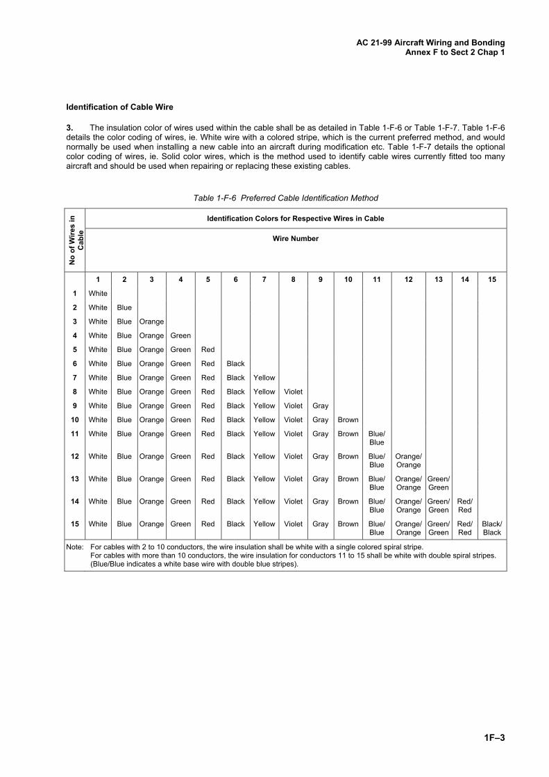
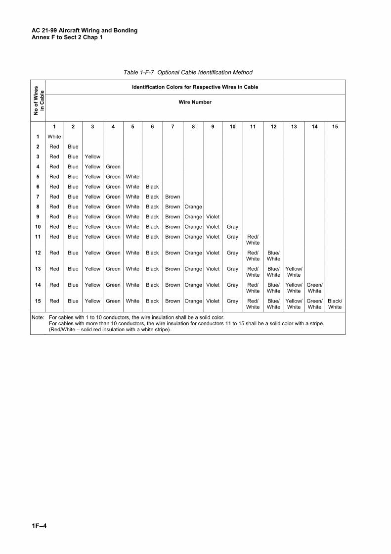
3. The insulation color of wires used within the cable shall be as detailed in Table 1-F-6 or Table 1-F-7. Table 1-F-6 details the color coding of wires, ie. White wire with a colored stripe, which is the current preferred method, and would normally be used when installing a new cable into an aircraft during modification etc. Table 1-F-7 details the optional color coding of wires, ie. Solid color wires, which is the method used to identify cable wires currently fitted too many aircraft and should be used when repairing or replacing these existing cables.
Table 1-F-6 Preferred Cable Identification Method
No
of W
ires
in
Cab
le
Identification Colors for Respective Wires in Cable
Wire Number
1 2 3 4 5 6 7 8 9 10 11 12 13 14 15
1 White
2 White Blue
3 White Blue Orange
4 White Blue Orange Green
5 White Blue Orange Green Red
6 White Blue Orange Green Red Black
7 White Blue Orange Green Red Black Yellow
8 White Blue Orange Green Red Black Yellow Violet
9 White Blue Orange Green Red Black Yellow Violet Gray
10 White Blue Orange Green Red Black Yellow Violet Gray Brown
11 White Blue Orange Green Red Black Yellow Violet Gray Brown Blue/Blue
12 White Blue Orange Green Red Black Yellow Violet Gray Brown Blue/Blue
Orange/ Orange
13 White Blue Orange Green Red Black Yellow Violet Gray Brown Blue/Blue
Orange/ Orange
Green/ Green
14 White Blue Orange Green Red Black Yellow Violet Gray Brown Blue/Blue
Orange/ Orange
Green/ Green
Red/Red
15 White Blue Orange Green Red Black Yellow Violet Gray Brown Blue/Blue
Orange/ Orange
Green/ Green
Red/Red
Black/Black
Note: For cables with 2 to 10 conductors, the wire insulation shall be white with a single colored spiral stripe. For cables with more than 10 conductors, the wire insulation for conductors 11 to 15 shall be white with double spiral stripes. (Blue/Blue indicates a white base wire with double blue stripes).
AC 21-99 Aircraft Wiring and Bonding Annex F to Sect 2 Chap 1
1F–4
Table 1-F-7 Optional Cable Identification Method
No
of W
ires
in C
able
Identification Colors for Respective Wires in Cable
Wire Number
1 2 3 4 5 6 7 8 9 10 11 12 13 14 15
1 White
2 Red Blue
3 Red Blue Yellow
4 Red Blue Yellow Green
5 Red Blue Yellow Green White
6 Red Blue Yellow Green White Black
7 Red Blue Yellow Green White Black Brown
8 Red Blue Yellow Green White Black Brown Orange
9 Red Blue Yellow Green White Black Brown Orange Violet
10 Red Blue Yellow Green White Black Brown Orange Violet Gray
11 Red Blue Yellow Green White Black Brown Orange Violet Gray Red/White
12 Red Blue Yellow Green White Black Brown Orange Violet Gray Red/White
Blue/ White
13 Red Blue Yellow Green White Black Brown Orange Violet Gray Red/White
Blue/ White
Yellow/ White
14 Red Blue Yellow Green White Black Brown Orange Violet Gray Red/White
Blue/ White
Yellow/ White
Green/ White
15 Red Blue Yellow Green White Black Brown Orange Violet Gray Red/White
Blue/ White
Yellow/ White
Green/ White
Black/White
Note: For cables with 1 to 10 conductors, the wire insulation shall be a solid color. For cables with more than 10 conductors, the wire insulation for conductors 11 to 15 shall be a solid color with a stripe. (Red/White – solid red insulation with a white stripe).
AC 21-99 Aircraft Wiring and Bonding
Annex G to Sect 2 Chap 1
1G–1
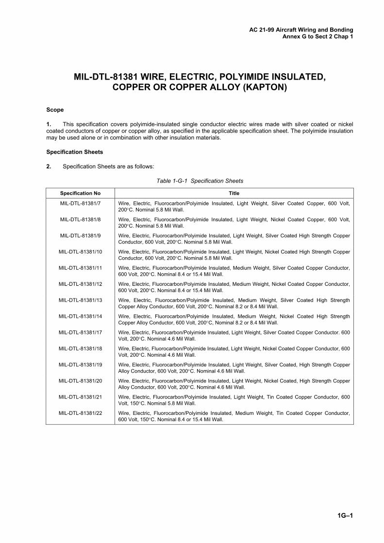
MIL-DTL-81381 WIRE, ELECTRIC, POLYIMIDE INSULATED, COPPER OR COPPER ALLOY (KAPTON)
Scope
1. This specification covers polyimide-insulated single conductor electric wires made with silver coated or nickel coated conductors of copper or copper alloy, as specified in the applicable specification sheet. The polyimide insulation may be used alone or in combination with other insulation materials.
Specification Sheets
2. Specification Sheets are as follows:
Table 1-G-1 Specification Sheets
Specification No Title
MIL-DTL-81381/7 Wire, Electric, Fluorocarbon/Polyimide Insulated, Light Weight, Silver Coated Copper, 600 Volt, 200C. Nominal 5.8 Mil Wall.
MIL-DTL-81381/8 Wire, Electric, Fluorocarbon/Polyimide Insulated, Light Weight, Nickel Coated Copper, 600 Volt, 200C. Nominal 5.8 Mil Wall.
MIL-DTL-81381/9 Wire, Electric, Fluorocarbon/Polyimide Insulated, Light Weight, Silver Coated High Strength Copper Conductor, 600 Volt, 200C. Nominal 5.8 Mil Wall.
MIL-DTL-81381/10 Wire, Electric, Fluorocarbon/Polyimide Insulated, Light Weight, Nickel Coated High Strength Copper Conductor, 600 Volt, 200C. Nominal 5.8 Mil Wall.
MIL-DTL-81381/11 Wire, Electric, Fluorocarbon/Polyimide Insulated, Medium Weight, Silver Coated Copper Conductor, 600 Volt, 200C. Nominal 8.4 or 15.4 Mil Wall.
MIL-DTL-81381/12 Wire, Electric, Fluorocarbon/Polyimide Insulated, Medium Weight, Nickel Coated Copper Conductor, 600 Volt, 200C. Nominal 8.4 or 15.4 Mil Wall.
MIL-DTL-81381/13 Wire, Electric, Fluorocarbon/Polyimide Insulated, Medium Weight, Silver Coated High Strength Copper Alloy Conductor, 600 Volt, 200C. Nominal 8.2 or 8.4 Mil Wall.
MIL-DTL-81381/14 Wire, Electric, Fluorocarbon/Polyimide Insulated, Medium Weight, Nickel Coated High Strength Copper Alloy Conductor, 600 Volt, 200C, Nominal 8.2 or 8.4 Mil Wall.
MIL-DTL-81381/17 Wire, Electric, Fluorocarbon/Polyimide Insulated, Light Weight, Silver Coated Copper Conductor. 600 Volt, 200C. Nominal 4.6 Mil Wall.
MIL-DTL-81381/18 Wire, Electric, Fluorocarbon/Polyimide Insulated, Light Weight, Nickel Coated Copper Conductor, 600 Volt, 200C. Nominal 4.6 Mil Wall.
MIL-DTL-81381/19 Wire, Electric, Fluorocarbon/Polyimide Insulated, Light Weight, Silver Coated, High Strength Copper Alloy Conductor, 600 Volt, 200C. Nominal 4.6 Mil Wall.
MIL-DTL-81381/20 Wire. Electric, Fluorocarbon/Polyimide Insulated, Light Weight, Nickel Coated, High Strength Copper Alloy Conductor, 600 Volt, 200C. Nominal 4.6 Mil Wall.
MIL-DTL-81381/21 Wire, Electric, Fluorocarbon/Polyimide Insulated, Light Weight, Tin Coated Copper Conductor, 600 Volt, 150C. Nominal 5.8 Mil Wall.
MIL-DTL-81381/22 Wire, Electric, Fluorocarbon/Polyimide Insulated, Medium Weight, Tin Coated Copper Conductor, 600 Volt, 150C. Nominal 8.4 or 15.4 Mil Wall.
AC 21-99 Aircraft Wiring and Bonding Annex G to Sect 2 Chap 1
1G–2
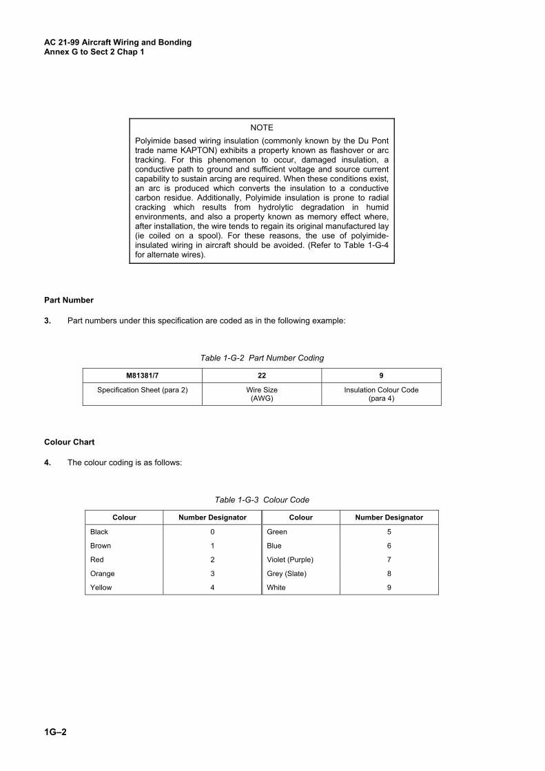
NOTE
Polyimide based wiring insulation (commonly known by the Du Pont trade name KAPTON) exhibits a property known as flashover or arc tracking. For this phenomenon to occur, damaged insulation, a conductive path to ground and sufficient voltage and source current capability to sustain arcing are required. When these conditions exist, an arc is produced which converts the insulation to a conductive carbon residue. Additionally, Polyimide insulation is prone to radial cracking which results from hydrolytic degradation in humid environments, and also a property known as memory effect where, after installation, the wire tends to regain its original manufactured lay (ie coiled on a spool). For these reasons, the use of polyimide-insulated wiring in aircraft should be avoided. (Refer to Table 1-G-4 for alternate wires).
Part Number
3. Part numbers under this specification are coded as in the following example:
Table 1-G-2 Part Number Coding
M81381/7 22 9
Specification Sheet (para 2) Wire Size (AWG)
Insulation Colour Code (para 4)
Colour Chart
4. The colour coding is as follows:
Table 1-G-3 Colour Code
Colour Number Designator Colour Number Designator
Black 0 Green 5
Brown 1 Blue 6
Red 2 Violet (Purple) 7
Orange 3 Grey (Slate) 8
Yellow 4 White 9

AC 21-99 Aircraft Wiring and Bonding
Annex G to Sect 2 Chap 1
1G–3
Cross Reference of Kapton to Non-Kapton Insulated Wires
5. When selecting a replacement wire, consideration must be given to the specific application and end use. Table 1-G-4, below, provides a direct equivalent for a Kapton wire, however this wire may not be the most appropriate or cost effective option in all applications.
Table 1-G-4. Equivalent Non-Kapton Insulated Wires
KAPTON NON-KAPTON
M81381/7 M22759/44
M81381/8 M22759/45
M81381/9 M22759/33
M81381/10 M22759/46
M81381/11 M22759/43
M81381/12 M22759/41
M81381/13 M22759/35
M81381/14 M22759/42
M81381/17 M22759/44
M81381/18 M22759/45
M81381/19 M22759/33
M81381/20 M22759/46
M81381/21 M22759/32
M81381/22 M22759/34

AC 21-99 Aircraft Wiring and Bonding Annex G to Sect 2 Chap 1
1G–4
Blank Page
AC 21-99 Aircraft Wiring and Bonding
Annex H to Sect 2 Chap 1
1H–1
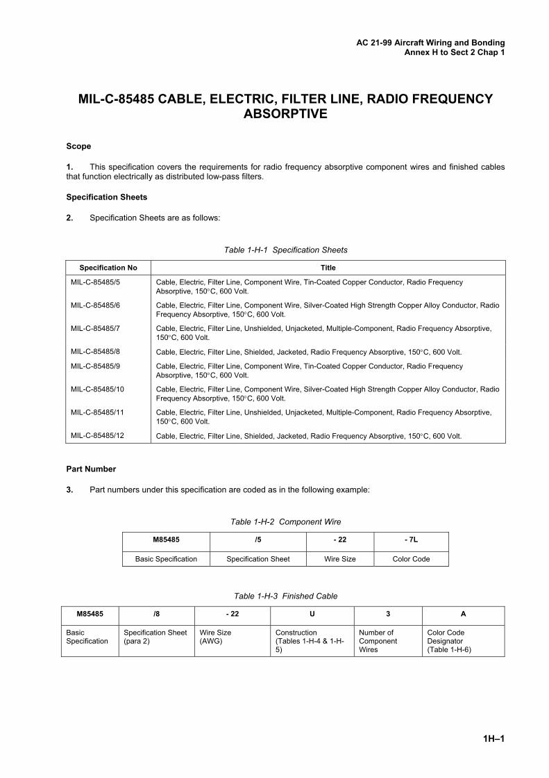
MIL-C-85485 CABLE, ELECTRIC, FILTER LINE, RADIO FREQUENCY ABSORPTIVE
Scope
1. This specification covers the requirements for radio frequency absorptive component wires and finished cables that function electrically as distributed low-pass filters.
Specification Sheets
2. Specification Sheets are as follows:
Table 1-H-1 Specification Sheets
Specification No Title
MIL-C-85485/5 Cable, Electric, Filter Line, Component Wire, Tin-Coated Copper Conductor, Radio Frequency Absorptive, 150C, 600 Volt.
MIL-C-85485/6 Cable, Electric, Filter Line, Component Wire, Silver-Coated High Strength Copper Alloy Conductor, Radio Frequency Absorptive, 150C, 600 Volt.
MIL-C-85485/7 Cable, Electric, Filter Line, Unshielded, Unjacketed, Multiple-Component, Radio Frequency Absorptive, 150C, 600 Volt.
MIL-C-85485/8 Cable, Electric, Filter Line, Shielded, Jacketed, Radio Frequency Absorptive, 150C, 600 Volt.
MIL-C-85485/9 Cable, Electric, Filter Line, Component Wire, Tin-Coated Copper Conductor, Radio Frequency Absorptive, 150C, 600 Volt.
MIL-C-85485/10 Cable, Electric, Filter Line, Component Wire, Silver-Coated High Strength Copper Alloy Conductor, Radio Frequency Absorptive, 150C, 600 Volt.
MIL-C-85485/11 Cable, Electric, Filter Line, Unshielded, Unjacketed, Multiple-Component, Radio Frequency Absorptive, 150C, 600 Volt.
MIL-C-85485/12 Cable, Electric, Filter Line, Shielded, Jacketed, Radio Frequency Absorptive, 150C, 600 Volt.
Part Number
3. Part numbers under this specification are coded as in the following example:
Table 1-H-2 Component Wire
M85485 /5 - 22 - 7L
Basic Specification Specification Sheet Wire Size Color Code
Table 1-H-3 Finished Cable
M85485 /8 - 22 U 3 A
Basic Specification
Specification Sheet (para 2)
Wire Size (AWG)
Construction (Tables 1-H-4 & 1-H-5)
Number of Component Wires
Color Code Designator (Table 1-H-6)

AC 21-99 Aircraft Wiring and Bonding Annex H to Sect 2 Chap 1
1H–2
Table 1-H-4 Shielded, Jacketed Cable Construction
Letter Code Conductor Type Shield Type
T Tin Coated Copper Tin Coated Copper
S Silver Coated Copper Silver Coated Copper
N Nickel Coated Copper Nickel Coated Copper
M Silver Coated High Strength Copper Alloy Silver Coated High Strength Copper Alloy
P Nickel Coated High Strength Copper Alloy Nickel Coated High Strength Copper Alloy
U Silver Coated High Strength Copper Alloy Tin Coated Copper
V Silver Coated High Strength Copper Alloy Silver Coated Copper
W Nickel Coated High Strength Copper Alloy Nickel Coated Copper
Note: Refer to MIL-C-85485 or publication sponsor for full details.
Table 1-H-5 Unshielded, Unjacketed Cable Construction
Letter Code Conductor Type
T Tin Coated Copper
S Silver Coated Copper
N Nickel Coated Copper
M Silver Coated High Strength Copper Alloy
P Nickel Coated High Strength Copper Alloy
Note: Refer to MIL-C-85485 or publication sponsor for full details.
Colour Chart
4. The color of the first component wire shall be light violet, designated by 7L. Any additional component wires shall be light violet with a colored stripe as per Table 1-H-6.
Table 1-H-6 Cable Colour Designation
Component Wire Number 1 2 3 4 5 6 7
Wire Insulation Base Color Light Violet Light Violet Light Violet Light Violet Light Violet Light Violet Light Violet
Stripe Color N/A Blue Orange Green Red Black Yellow
Note: Refer to MIL-C-85485 or publication sponsor for full details.

AC 21-99 Aircraft Wiring and Bonding
Annex I to Sect 2 Chap 1
1I–1
CURRENT RATINGS OF WIRE AND MAXIMUM ALLOWABLE NICKED OR BROKEN STRANDS
Table 1-I-1 Current Rating Of Wires In Amps (SAE AS 50881)
Wires in Bundles, Groups or Harnesses (Note 1)
Wire in Free Air & Ambient 70°C (Note 2)
Conductor Material
Wire Size
Wire Temp Rating Wire Temp Rating
105°C 150°C 200°C 105°C 150°C 200°C
Copper or 22 3 5 6 9 12.5 16
Copper Alloy 20 4 7 9 11 17 21
18 6 9 12 15 22.5 28
16 7 11 14 17 26 33
14 10 14 18 23 35 44
12 13 19 25 31 47 60
10 17 26 32 41 62 78
8 38 57 71 64 90 125
6 50 76 97 82 125
4 68 103 133 110 170
2 95 141 179 155
1 113 166 210 185
1/0 128 192 243 210
2/0 147 222 285 240
3/0 172 262 335 276
4/0 204 310 395 340
Aluminium 8 30 45
6 40 61
4 54 82
2 76 113
1 90 133
1/0 102 153
2/0 117 178
3/0 138 209
4/0 163 248
Notes:
1 Rating for 70°C ambient, 33 or more wires in harness with no more than 20% harness current capacity being used at operating altitude of 60,000 ft.
2 Rating of wires in FREE air at ambient temperature of 70°C.
AC 21-99 Aircraft Wiring and Bonding Annex I to Sect 2 Chap 1
1I–2
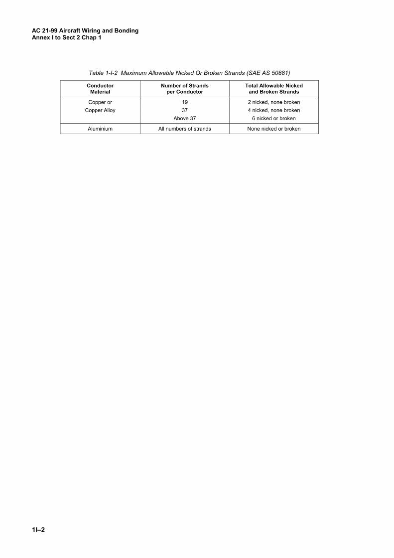
Table 1-I-2 Maximum Allowable Nicked Or Broken Strands (SAE AS 50881)
Conductor Material
Number of Strands per Conductor
Total Allowable Nicked and Broken Strands
Copper or 19 2 nicked, none broken
Copper Alloy 37 4 nicked, none broken
Above 37 6 nicked or broken
Aluminium All numbers of strands None nicked or broken
AC 21-99 Aircraft Wiring and Bonding
Annex J to Sect 2 Chap 1
1J–1
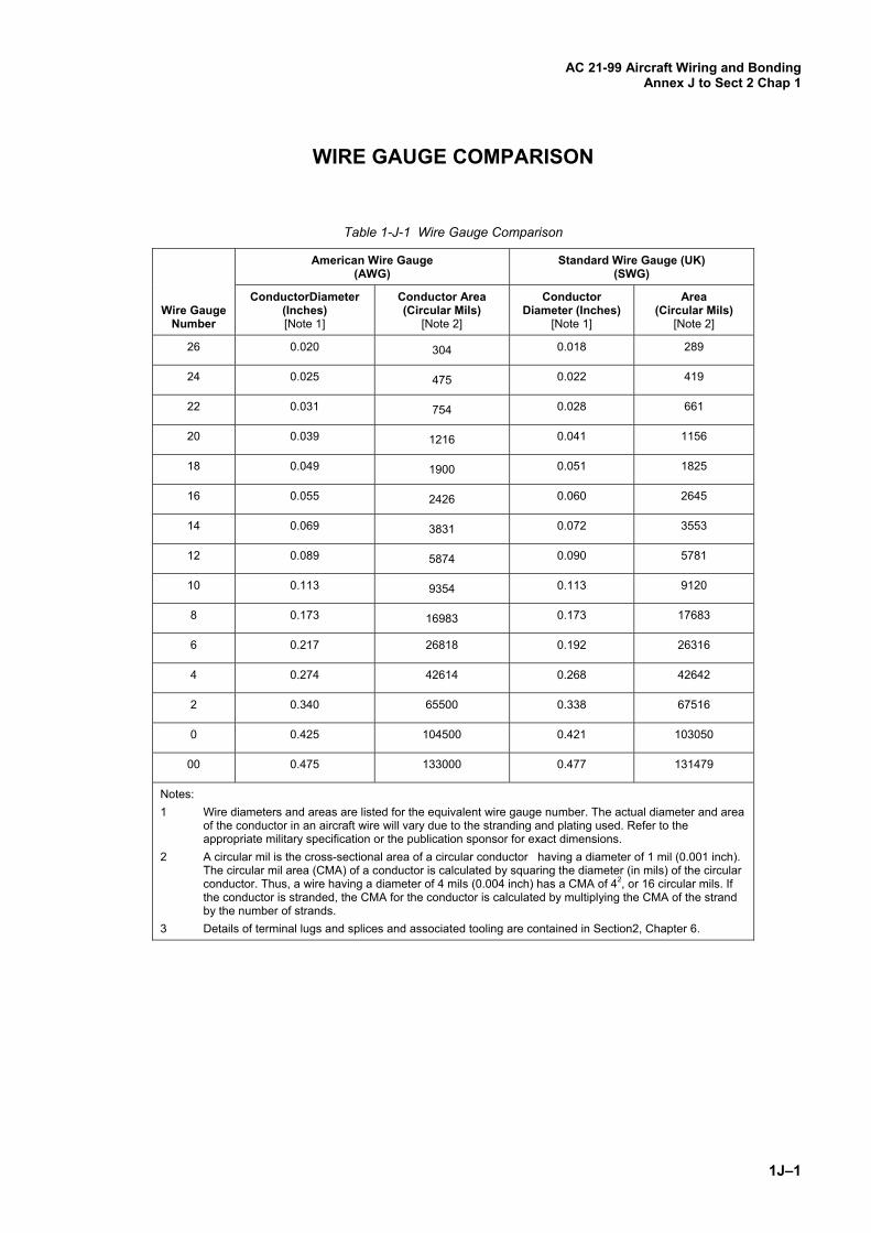
WIRE GAUGE COMPARISON
Table 1-J-1 Wire Gauge Comparison
Wire Gauge
Number
American Wire Gauge (AWG)
Standard Wire Gauge (UK) (SWG)
ConductorDiameter (Inches) [Note 1]
Conductor Area (Circular Mils)
[Note 2]
Conductor Diameter (Inches)
[Note 1]
Area (Circular Mils)
[Note 2]
26 0.020 304 0.018 289
24 0.025 475 0.022 419
22 0.031 754 0.028 661
20 0.039 1216 0.041 1156
18 0.049 1900 0.051 1825
16 0.055 2426 0.060 2645
14 0.069 3831 0.072 3553
12 0.089 5874 0.090 5781
10 0.113 9354 0.113 9120
8 0.173 16983 0.173 17683
6 0.217 26818 0.192 26316
4 0.274 42614 0.268 42642
2 0.340 65500 0.338 67516
0 0.425 104500 0.421 103050
00 0.475 133000 0.477 131479
Notes:
1 Wire diameters and areas are listed for the equivalent wire gauge number. The actual diameter and area of the conductor in an aircraft wire will vary due to the stranding and plating used. Refer to the appropriate military specification or the publication sponsor for exact dimensions.
2 A circular mil is the cross-sectional area of a circular conductor having a diameter of 1 mil (0.001 inch). The circular mil area (CMA) of a conductor is calculated by squaring the diameter (in mils) of the circular conductor. Thus, a wire having a diameter of 4 mils (0.004 inch) has a CMA of 42, or 16 circular mils. If the conductor is stranded, the CMA for the conductor is calculated by multiplying the CMA of the strand by the number of strands.
3 Details of terminal lugs and splices and associated tooling are contained in Section2, Chapter 6.
AC 21-99 Aircraft Wiring and Bonding Annex J to Sect 2 Chap 1
1J–2
Blank Page