Embed Size (px)
Citation preview

WIUser
Revision
4 June 2
Copyright
P Ser’s Gui
n 1.0
2013
t © 2013 Ti
erieside
irade
s

TIRADE Page 2
Copyright © 2013 Tirade
This user’s guide and the software described in it are copyrighted with all rights reserved. No part of this publication may be reproduced, transmitted, transcribed, stored in a retrieval system, or translated into any language in any form by any means without the written permission of Observint Technologies.
Notice Observint Technologies reserves the right to change specifications without prior notice.
While the information in this manual has been compiled with great care, it may not be deemed an assurance of product characteristics. Observint Technologies shall be liable only to the degree specified in the terms of sale and delivery.
The reproduction and distribution of the documentation and software supplied with this product and the use of its contents is subject to written authorization from Observint Technologies.
Trademarks Tirade logo is trademark of Observint Technologies.
All other registered and unregistered trademarks in this document are the sole property of their respective owners.

User’s Guide Contents
TIRADE Page 3
Contents
Copyright .......................................................................................................................................... 2 Notice ............................................................................................................................................... 2 Trademarks ...................................................................................................................................... 2
CONTENTS ........................................................................................................................................ 3
ABOUT THIS GUIDE .......................................................................................................................... 5
Prerequisite Skills and Knowledge .................................................................................................... 5 Conventions Used in this Document ................................................................................................. 5 Abbreviation List ............................................................................................................................... 5
INTRODUCTION ................................................................................................................................. 7
Deployment Scenarios ...................................................................................................................... 7 HotSpot ......................................................................................................................................... 7 Point to Multipoint .......................................................................................................................... 8 Light PTP ...................................................................................................................................... 8
INITIAL DEVICE SETUP ..................................................................................................................... 9
Initial AP Setup ................................................................................................................................. 9 Initial Station Setup ......................................................................................................................... 12
NETWORK OPERATION MODES .................................................................................................... 16
Bridge Mode ................................................................................................................................... 16 Router Mode ................................................................................................................................... 16
GENERAL DEVICE OPERATION .................................................................................................... 17
Web Management Structure ........................................................................................................... 17 Appling and Saving Configuration Changes ................................................................................... 18
CONFIGURATION GUIDE ................................................................................................................ 19
Status ............................................................................................................................................. 19 Information .................................................................................................................................. 19 Network ....................................................................................................................................... 20 Wireless ...................................................................................................................................... 20 Routes ......................................................................................................................................... 21 ARP ............................................................................................................................................ 21
Configuration .................................................................................................................................. 22 Network ....................................................................................................................................... 22 Bridge Mode ................................................................................................................................ 22
IP Settings .................................................................................................................................................... 23 VLAN to SSID Mapping ................................................................................................................................ 23 Management VLAN ...................................................................................................................................... 23
Router Mode ............................................................................................................................... 25 WAN Settings ............................................................................................................................................... 26 LAN Network Settings .................................................................................................................................. 28 LAN DHCP Settings ..................................................................................................................................... 29
Wireless ...................................................................................................................................... 30 Wireless Mode: Access Point (auto WDS) .................................................................................. 31
Basic Wireless Settings ................................................................................................................................ 31 Security Settings ........................................................................................................................................... 32 Advanced Wireless Settings......................................................................................................................... 33
Wireless Mode: Station ............................................................................................................... 35 Basic Wireless Settings ................................................................................................................................ 35 Security Settings ........................................................................................................................................... 35

User’s Guide Contents
TIRADE Page 4
Advanced Wireless Settings......................................................................................................................... 37 Wireless Mode: iPoll Access Point .............................................................................................. 38
Basic Settings ............................................................................................................................................... 38 Security Settings ........................................................................................................................................... 39 Advanced Wireless Settings......................................................................................................................... 40
Wireless Mode: iPoll Station ........................................................................................................ 41 Basic Settings ............................................................................................................................................... 41 Security Settings ........................................................................................................................................... 41 Advanced Wireless Settings......................................................................................................................... 42
Virtual AP .................................................................................................................................... 43 Wireless ACL .............................................................................................................................. 44 Traffic Shaping ............................................................................................................................ 44
Limit all traffic ................................................................................................................................................ 45 Limit per IP traffic .......................................................................................................................................... 45
Port Forwarding ........................................................................................................................... 45 Static Routes ............................................................................................................................... 47
Services .......................................................................................................................................... 47 WNMS ......................................................................................................................................... 47 System alerts .............................................................................................................................. 48
SNMP Traps Settings ................................................................................................................................... 49 SMTP Settings .............................................................................................................................................. 49
SNMP .......................................................................................................................................... 49 Clock/NTP ................................................................................................................................... 50 SSH ............................................................................................................................................ 50 HTTP ........................................................................................................................................... 51
System ........................................................................................................................................... 52 Administration ............................................................................................................................. 52
Device settings ............................................................................................................................................. 52 Account settings ........................................................................................................................................... 52 System functions .......................................................................................................................................... 53
Log .............................................................................................................................................. 53 LED Control ................................................................................................................................ 54 Firmware Upgrade ...................................................................................................................... 55
Tools ............................................................................................................................................... 56 Antenna Alignment ...................................................................................................................... 56 Site Survey .................................................................................................................................. 56 Delayed Reboot .......................................................................................................................... 57 Ping ............................................................................................................................................. 58 Traceroute ................................................................................................................................... 59 Spectrum Analyzer ...................................................................................................................... 59
UNIVERSAL ACCESS METHOD (UAM) .......................................................................................... 61
UAM Overview ................................................................................................................................ 61 UAM Configuration ......................................................................................................................... 61
White/Black List ........................................................................................................................... 63
APPENDIX ........................................................................................................................................ 64
A) Resetting Device to Factory Defaults ......................................................................................... 64 B) RADIUS Attributes ..................................................................................................................... 65
General Attributes ....................................................................................................................... 65 WISPr Attributes .......................................................................................................................... 66 ChilliSpot Attributes ..................................................................................................................... 66
INDEX ............................................................................................................................................... 68

User’s Guide About this Guide
TIRADE Page 5
About this Guide
Prerequisite Skills and Knowledge To use this document effectively, you should have a working knowledge of Local Area Networking (LAN) concepts and wireless Internet access infrastructures.
Conventions Used in this Document The following typographic conventions and symbols are used throughout this document:
Additional information that may be helpful but which is not required.
Important information that should be observed.
bold Menu commands, buttons, input fields, links, and configuration keys are displayed in bold
italic References to sections inside the document are displayed in italic.
code File names, directory names, form names, system-generated output, and user typed entries are displayed in constant-width type
Abbreviation List
Abbreviation Description
ACL Access Control List
AES Advanced Encryption Standard
AMSDU Aggregated Mac Service Data Unit
AP Access Point
CRC Cyclic Redundancy Check
DHCP Dynamic Host Control Protocol
EAP Extensible Authentication Protocol
GHz Gigahertz
GMT Greenwich Mean Time.
GUI Graphical User Interface
IEEE Institute of Electrical and Electronics Engineers
ISP Internet Service Provider
IP Internet Protocol
LAN Local Area Network
LED Light-Emitting Diode
MAC Media Access Control

User’s Guide About this Guide
TIRADE Page 6
Abbreviation Description
Mbps Megabits per second
MHz Megahertz
MIMO Multiple Input, Multiple Output
MSCHAPv2 Microsoft version of the Challenge-handshake authentication protocol, CHAP.
NAT Network address translation – translation of IP addresses (and ports)
PC Personal Computer
PDA Personal Digital Assistant
PTP Point To Point
PTMP Point To Multi Point
PSK Pre-Shared Key
QoS Quality of Service
PEAP Protected Extensible Authentication Protocol
RSSI Received Signal Strength Indication – received signal strength in mV, measured on BNC outdoor unit connector
RX Receive
SISO Simple Input, Simple Output
SNMP Simple Network Management Protocol
SMTP Simple Mail Transfer Protocol
SSID Service Set Identifier
TCP Transmission Control Protocol
TKIP Temporal Key Integrity Protocol
TTLS Tunneled Transport Layer Security (EAP-TTLS) protocol
TX Transmission
UDP User Datagram Protocol
UAM Universal Access Method
VLAN Virtual Local Area Network
VoIP Voice over Internet Protocol
WDS Wireless Distribution System
WEP Wired Equivalent Privacy
WISPr Wireless Internet Service Provider roaming
WLAN Wireless Local Area Network
WPA Wi-Fi Protected Access
WPA2 Wi-Fi Protected Access 2
User’s G
TIRADE
IntroTirade WwirelessWIP (AcWIP worsimple nIEEE 80functiona
Deplo
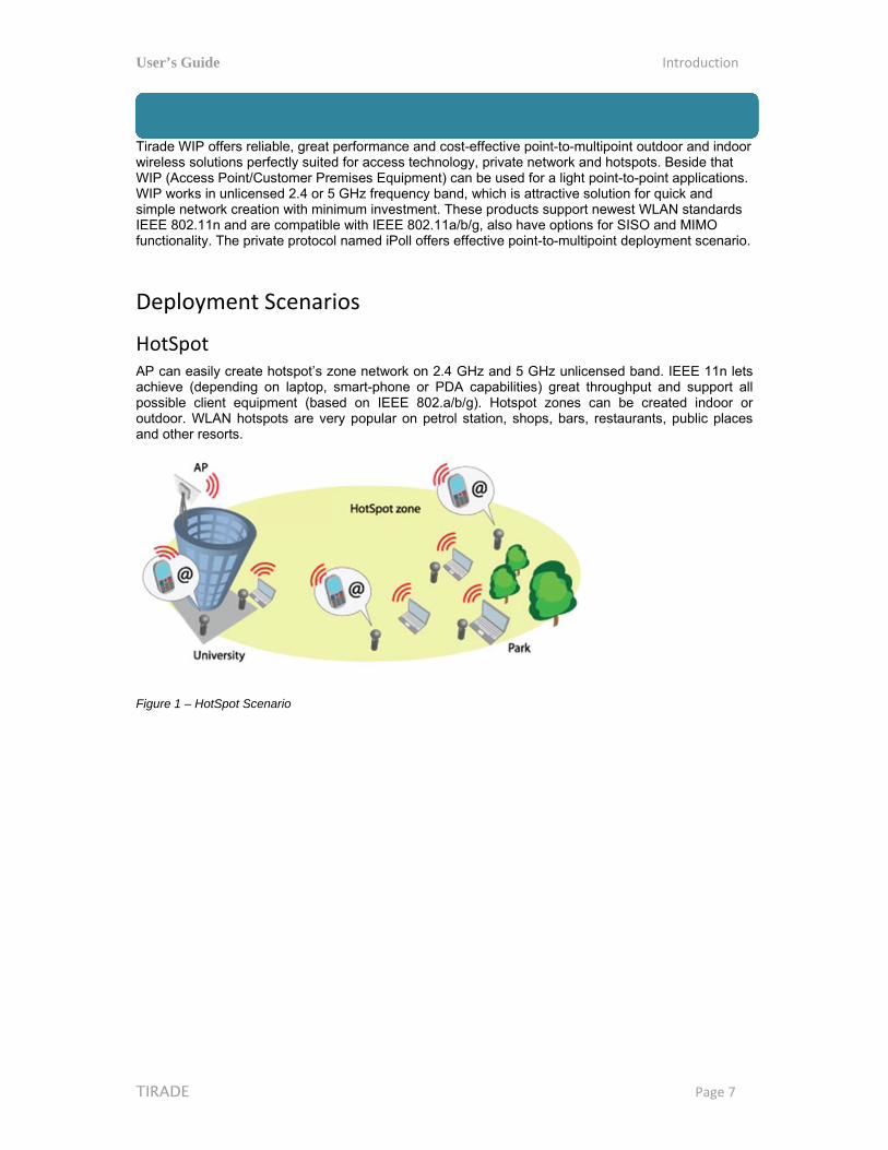
HotSpAP can achieve possibleoutdoor.and othe
Figure 1 –
Guide
E
oductioWIP offers res solutions peccess Point/Crks in unlicennetwork creat02.11n and aality. The pri
oyment
pot easily create(depending
e client equi. WLAN hotser resorts.
– HotSpot Sce
on liable, great
erfectly suiteCustomer Prensed 2.4 or 5tion with minre compatiblvate protoco
t Scenar
e hotspot’s zon laptop,
ipment (basspots are ve
enario
performanced for access emises Equip5 GHz frequenimum investle with IEEE ol named iPo
ios
zone networksmart-phoneed on IEEE
ery popular o
e and cost-eftechnology,
pment) can bency band, wtment. These802.11a/b/g
oll offers effec
k on 2.4 GHze or PDA caE 802.a/b/g)on petrol sta
ffective point private netwbe used for a
which is attrae products sug, also have octive point-to
z and 5 GHzapabilities) g. Hotspot z
ation, shops,
t-to-multipoinwork and hotsa light point-tctive solutionupport newesoptions for So-multipoint d
z unlicensed great througones can b bars, resta
Introd
P
nt outdoor anspots. Besidto-point appln for quick anst WLAN sta
SISO and MIMdeployment s
band. IEEEhput and su
be created iurants, publi
duction
Page 7
nd indoor e that ications. nd
andards MO scenario.
E 11n lets upport all ndoor or ic places

User’s Guide Introduction
TIRADE Page 8
Point to Multipoint This is the IEEE 802.11n wireless multipoint which delivers several times higher throughput than 802.11a/g. The WIP supports a private wireless point to multipoint protocol called iPoll which allows connecting more than one iPoll Stations to the iPoll Access Point thus creating a robust point to multi point network.
Figure 2 – Point to Multipoint Scenario
Light PTP Tirade WIP supports access point and station operating modes, therefore point-to-point can be created from AP and Station or from 2 Station’s or from 2 AP’s. For simplicity two Stations can be used because they have integrated directional antennas. There are available options for SISO and MIMO PTPs. Maximum achievable real data throughput is up to 160 Mbps.
Figure 3 – Light PTP Scenario

User’s Guide Initial Device Setup
TIRADE Page 9
Initial Device Setup The default product address is 192.168.2.66.
To access the Web management interface, configure your PC with a static IP address on the 192.168.2.0 subnet with mask 255.255.255.0. Connect the AP device in to the same physical network as your PC. Open the Web browser and type the default IP address of the AP device https://192.168.2.66/ and the login page will be loaded. Enter default administrator login settings:
Figure 4 – Login Page
The default administrator login settings are: Login: admin Password: admin01
After successful administrator login you will see the main page of the device Web management interface. The device now is ready for configuration.
Initial AP Setup Follow the steps for initial wireless Access Point setup that will be prepared to accept wireless Station connections (refer to the section Initial Station Setup for instructions).
Step 1. Connect an Ethernet cable between your computer and the AP.
Step 2. Make sure your computer is set to the same subnet as the AP, i.e. 192.168.2.150
Step 3. Start your Web browser.
Step 4. Each devices uses following default settings:
WAN IP: 192.168.2.66 Subnet mask: 255.255.255.0 Username: admin Password: admin01

User’s Guide Initial Device Setup
TIRADE Page 10
The initial login screen looks as follow:
Step 5. Enter the default password, and then press the Login button to enter the AP web management page.
Step 6. Navigate to the Configuration | Network tab and choose the Router network mode with NAT enabled, Static IP enabled on WAN side, LAN settings with DHCP server enabled (to loan an IP addresses for connected clients) on LAN side and click Save&Apply:

User’s Guide Initial Device Setup
TIRADE Page 11
Step 7. Navigate to the Configuration | Wireless tab, choose Access Point wireless mode with WDS enabled, specify the SSID with Broadcast enabled, Security parameters and IEEE mode and click Save&Apply:
Step 8. Verify connection. Navigate to Status | Information menu to check if the Stations are successfully connected to the WIP device:
User’s Guide Initial Device Setup
TIRADE Page 12
Initial Station Setup
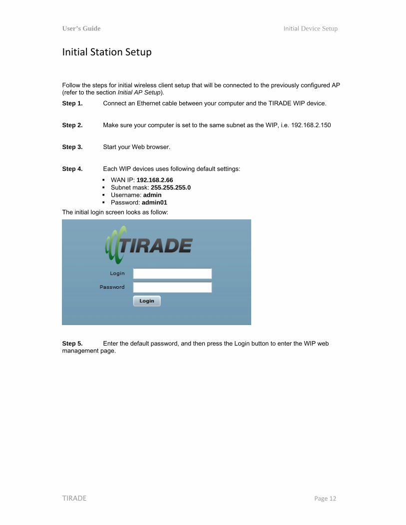
Follow the steps for initial wireless client setup that will be connected to the previously configured AP (refer to the section Initial AP Setup).
Step 1. Connect an Ethernet cable between your computer and the TIRADE WIP device.
Step 2. Make sure your computer is set to the same subnet as the WIP, i.e. 192.168.2.150
Step 3. Start your Web browser.
Step 4. Each WIP devices uses following default settings:
WAN IP: 192.168.2.66 Subnet mask: 255.255.255.0 Username: admin Password: admin01
The initial login screen looks as follow:
Step 5. Enter the default password, and then press the Login button to enter the WIP web management page.
User’s Guide Initial Device Setup
TIRADE Page 13
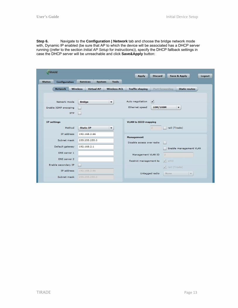
Step 6. Navigate to the Configuration | Network tab and choose the bridge network mode with, Dynamic IP enabled (be sure that AP to which the device will be associated has a DHCP server running ((refer to the section Initial AP Setup for instructions)), specify the DHCP fallback settings in case the DHCP server will be unreachable and click Save&Apply button:

User’s Guide Initial Device Setup
TIRADE Page 14
Step 7. Navigate to the Configuration | Wireless tab, choose Station WDS wireless mode, click Scan button near the SSID entry field to choose the SSID of the AP where the station will be associated to. Specify the Security parameters for the AP, check IEEE mode (these settings must conform with AP wireless settings) and click Save&Apply:
Step 8. Verify connection. Navigate to the Status | Network page. The Network page will show main network information about association with AP:

User’s Guide Initial Device Setup
TIRADE Page 15
The main Status | Information page will display wireless information of the link with access point. The connection status must be displayed as Connected and progress bars indicating the quality of the connection must be displayed:
User’s Guide Network Operation Modes
TIRADE Page 16
Network Operation Modes The device can operate as transparent Bridge or Router.
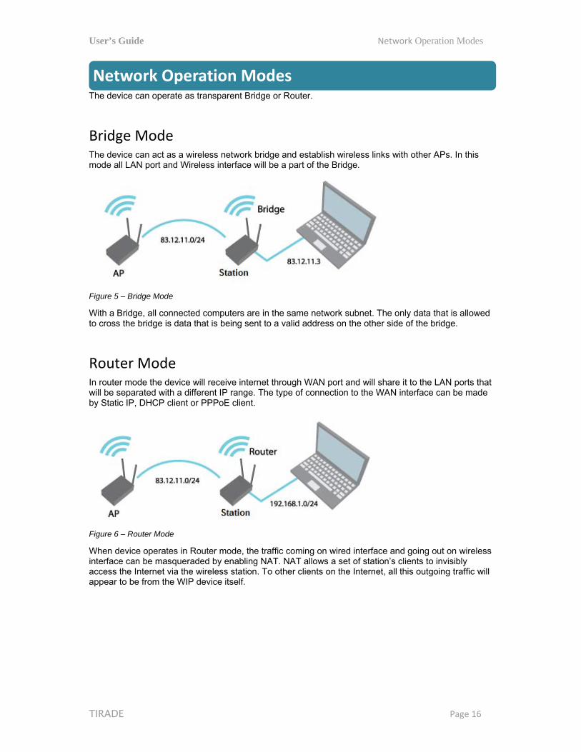
Bridge Mode The device can act as a wireless network bridge and establish wireless links with other APs. In this mode all LAN port and Wireless interface will be a part of the Bridge.
Figure 5 – Bridge Mode
With a Bridge, all connected computers are in the same network subnet. The only data that is allowed to cross the bridge is data that is being sent to a valid address on the other side of the bridge.
Router Mode In router mode the device will receive internet through WAN port and will share it to the LAN ports that will be separated with a different IP range. The type of connection to the WAN interface can be made by Static IP, DHCP client or PPPoE client.
Figure 6 – Router Mode
When device operates in Router mode, the traffic coming on wired interface and going out on wireless interface can be masqueraded by enabling NAT. NAT allows a set of station’s clients to invisibly access the Internet via the wireless station. To other clients on the Internet, all this outgoing traffic will appear to be from the WIP device itself.
User’s Guide General Device Operation
TIRADE Page 17
General Device Operation
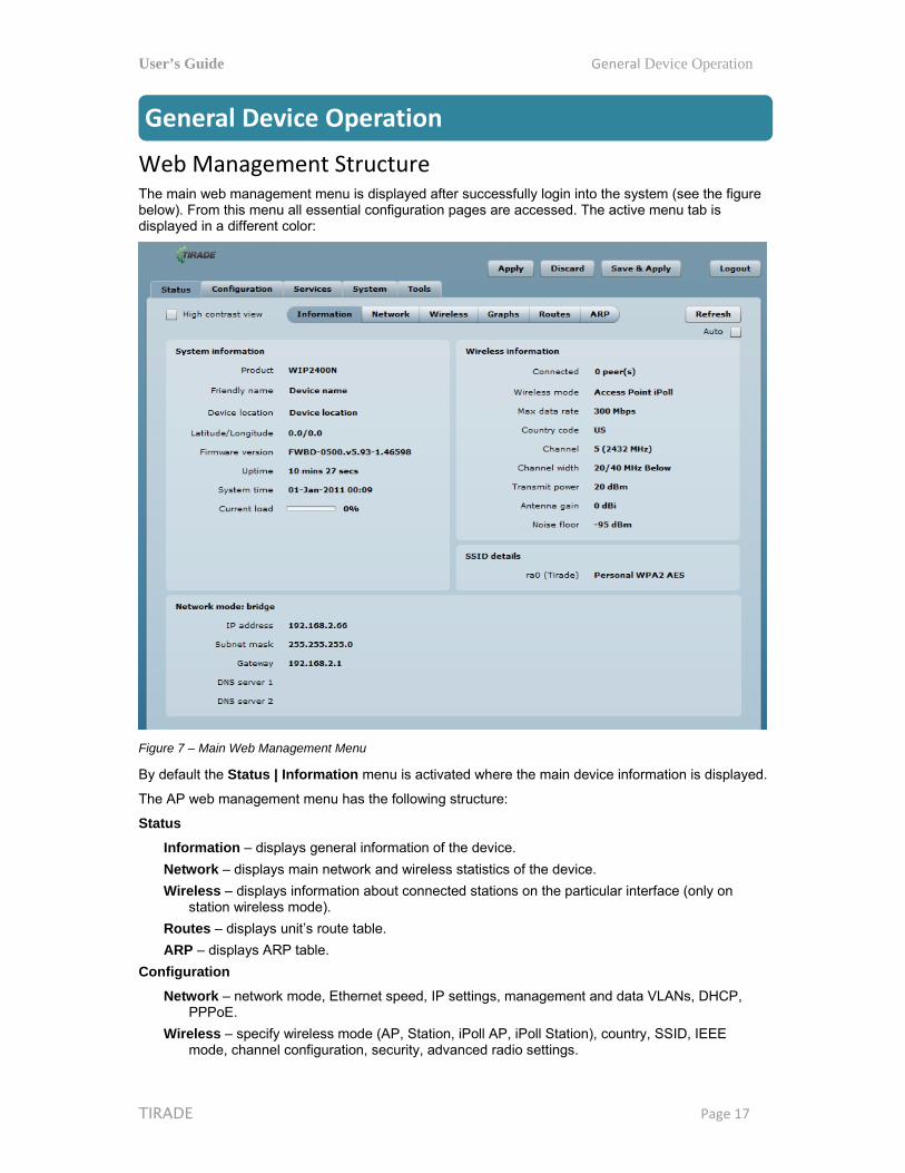
Web Management Structure The main web management menu is displayed after successfully login into the system (see the figure below). From this menu all essential configuration pages are accessed. The active menu tab is displayed in a different color:
Figure 7 – Main Web Management Menu
By default the Status | Information menu is activated where the main device information is displayed.
The AP web management menu has the following structure:
Status
Information – displays general information of the device.
Network – displays main network and wireless statistics of the device.
Wireless – displays information about connected stations on the particular interface (only on station wireless mode).
Routes – displays unit’s route table.
ARP – displays ARP table.
Configuration
Network – network mode, Ethernet speed, IP settings, management and data VLANs, DHCP, PPPoE.
Wireless – specify wireless mode (AP, Station, iPoll AP, iPoll Station), country, SSID, IEEE mode, channel configuration, security, advanced radio settings.
User’s Guide General Device Operation
TIRADE Page 18
Virtual AP – create and setup virtual AP (only in AP wireless mode).
Wireless ACL – access control by MAC address (only in AP and IPoll AP wireless modes).
Traffic shaping – download and upload traffic control.
Port forwarding – port forwarding rules (only in router network mode for AP and IPoll AP).
Static routes – static route rules (only in router network mode for AP and IPoll AP).
Services
WNMS – set WNMS server/collector URL allowing remote device configuration and monitoring.
System Alerts – set alerts which can be sent via SNMP Traps or/and SMTP notifications.
SNMP – SNMP service settings allowing remote device monitoring.
Clock/NTP – set device date manually or enable and configure NTP service.
SSH – control SSH connection.
HTTP – control HTTP connection.
System
Administration – change password, reboot, restore factory default settings, backup/restore configuration, troubleshooting file support.
Log – view device log, set system log forwarding settings.
LED – control operation of LEDs.
Firmware upgrade – upgrade device firmware.
Tools
Antenna alignment – measure received signal quality of the wireless link to align antenna in the best direction.
Site Survey – information about other wireless networks in the local area.
Delayed reboot – setup delayed reboot for WIP unit.
Ping – perform ping command.
Traceroute – perform graphical traceroute command.
Spectrum analyzer – check the signal strength on available channels.
Appling and Saving Configuration Changes There are three general buttons located on the right top corner of the WEB GUI allowing managing device configuration:
Apply – if pressed new configuration settings are applied instantly. It will take few seconds and the device will be running with new settings. It should be noted that pressing Apply button settings are not written to the permanent memory. Therefore, if the device is rebooted it will start with old configuration settings.
Discard – if pressed parameter changes are discarded. It should be noted that if Apply or Save&Apply is pressed it is not possible to discard changes.
Save&Apply – if pressed new configuration settings are applied instantly and written to the permanent memory.
It is not required to press Apply or Save&Apply in every Web GUI tab. The device remembers all changes made in every tab and after action button is used, all changes will be applied.
User’s Guide Configuration Guide
TIRADE Page 19
Configuration Guide This document contain product‘s powerful web management interface configuration description allowing setups ranging from very simple to very complex.
Status
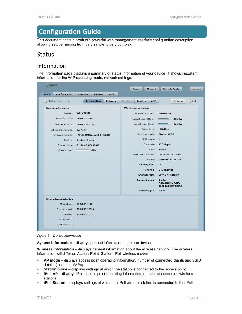
Information The Information page displays a summary of status information of your device. It shows important information for the WIP operating mode, network settings.
Figure 8 – Device Information
System information – displays general information about the device.
Wireless information – displays general information about the wireless network. The wireless information will differ on Access Point, Station, iPoll wireless modes:
AP mode – displays access point operating information, number of connected clients and SSID details (including VAPs).
Station mode – displays settings at which the station is connected to the access point. iPoll AP – displays iPoll access point operating information, number of connected wireless
stations. iPoll Station – displays settings at which the iPoll wireless station is connected to the iPoll
User’s Guide Configuration Guide
TIRADE Page 20
access point.
Network mode – displays short summary of the WIP current network configuration (bridge or router).
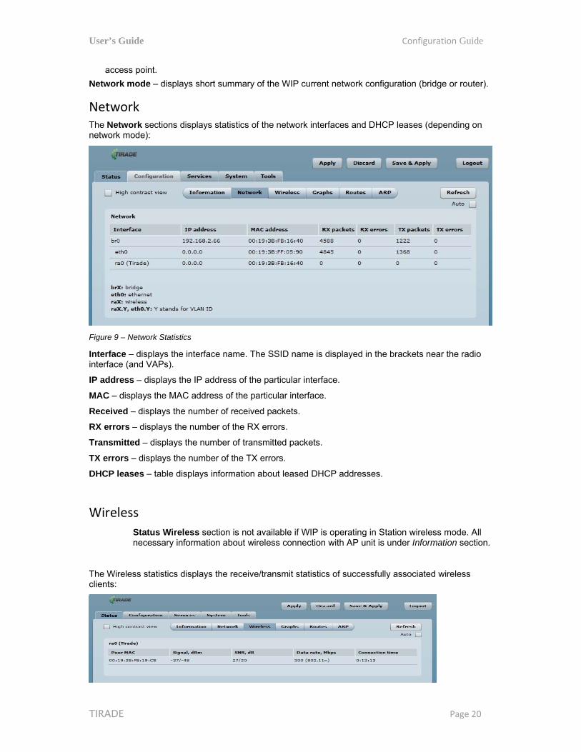
Network The Network sections displays statistics of the network interfaces and DHCP leases (depending on network mode):
Figure 9 – Network Statistics
Interface – displays the interface name. The SSID name is displayed in the brackets near the radio interface (and VAPs).
IP address – displays the IP address of the particular interface.
MAC – displays the MAC address of the particular interface.
Received – displays the number of received packets.
RX errors – displays the number of the RX errors.
Transmitted – displays the number of transmitted packets.
TX errors – displays the number of the TX errors.
DHCP leases – table displays information about leased DHCP addresses.
Wireless
Status Wireless section is not available if WIP is operating in Station wireless mode. All necessary information about wireless connection with AP unit is under Information section.
The Wireless statistics displays the receive/transmit statistics of successfully associated wireless clients:

User’s Guide Configuration Guide
TIRADE Page 21
Figure 10 - Access Point's Wireless Statistics
In case the access point has more than one wireless interface (VAPs), the appropriate number of tables with information about connected wireless clients will be displayed.
Peer MAC – displays MAC address of the successfully connected wireless client.
Signal – indicates the signal strength of the access point main and auxiliary antennas that the station communicates with displayed dBm.
Noise – displays the noise level in dBm.
IEEE mode – displays the IEEE mode at which the access point communicates with the particular station.
Data rate – displays the data rate at which the access point communicates with the particular station.
Connection time – displays the duration of the session.
Routes The Routes page displays the routing table for each interface:
Figure 11 – Routes Table
ARP The ARP page displays the ARP (Address Resolution Protocol) table currently recorded on the device. Use Refresh button to reload ARP table results.
Figure 12 – ARP Table Records

User’s Guide Configuration Guide
TIRADE Page 22
Configuration
Network The Configuration | Network page allows you to control the network configuration and settings of the device. First, the device operation mode must be defined to work as a bridge or router. The content of the window varies depending on your selection:
Figure 13 – Network Mode Options
Network mode - choose the device operating mode [bridge/router]
Bridge – in this mode the device works as transparent bridge interconnecting wireless network and LAN port. The Firewall related functions and NAT are not available in this mode.
Router – in this mode the device works as router between wireless network and all LAN ports.
Ethernet speed – configures the Ethernet link speed and the duplex mode of the Ethernet port. Choose "auto" for automatic detection of link speed and duplex mode.
Network settings will vary according to the selected Network mode. The Bridge mode allows configuring device LAN IP settings, while the Router mode requires more parameters such as LAN network settings, WAN network settings, LAN DHCP settings.
Bridge Mode
Port forwarding and Static routes are not available on Bridge mode.
When device is configured to operate in Bridge mode, only device LAN settings should be configured on the Network page:
Figure 14 – Bridge Mode Settings
User’s Guide Configuration Guide
TIRADE Page 23
IP Settings
When assigning IP address make sure that the chosen IP address is unused and belongs to the same IP subnet as your wired LAN, otherwise you will lose the connection to the device from your current PC. If you enable the DHCP client, the browser will lose the connection after saving, because the IP address assigned by the DHCP server is not predictable.
Method – specify IP reception method: IP addresses can either be retrieved from a DHCP server or configured manually:
Static IP – the IP address must be specified manually. Dynamic IP – the IP address for this device will be assigned from the DHCP server. If DHCP
server is not available, the device will try to get an IP. If has no success, it will use a fallback IP address (default fallback IP is 192.168.2.66). The fallback IP settings can be changed to custom values.
IP Address – specify IP address for device
Subnet mask – specify a subnet mask for device.
Default gateway – specify a gateway IP address for device.
DNS server – specify the Domain Naming Server.
Enable IP alias – specify the alternative IP address and the netmask for WIP unit management.
VLAN to SSID Mapping
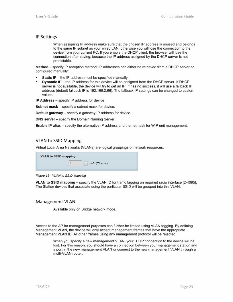
Virtual Local Area Networks (VLANs) are logical groupings of network resources.
Figure 15 - VLAN to SSID Mapping
VLAN to SSID mapping – specify the VLAN ID for traffic tagging on required radio interface [2-4095]. The Station devices that associate using the particular SSID will be grouped into this VLAN.
Management VLAN
Available only on Bridge network mode.
Access to the AP for management purposes can further be limited using VLAN tagging. By defining Management VLAN, the device will only accept management frames that have the appropriate Management VLAN ID. All other frames using any management protocol will be rejected.
When you specify a new management VLAN, your HTTP connection to the device will be lost. For this reason, you should have a connection between your management station and a port in the new management VLAN or connect to the new management VLAN through a multi-VLAN router.

User’s Guide Configuration Guide
TIRADE Page 24
Figure 16 – Management VLAN Settings
Enable – select to enable a VLAN tagging for management traffic.
Management VLAN ID – specify the VLAN ID [2-4095]. When device interfaces are configured with a specific VLAN ID value, only management frames that matching configured VLAN ID will be accepted by device.
Restrict management to interfaces – select interfaces that will be restricted with management VLAN.

User’s Guide Configuration Guide
TIRADE Page 25
Router Mode This section allows customizing parameters of the Router to suit the needs of network, including ability to use the built-in DHCP server. When device is configured to operate as Router, the following sections should be specified: WAN network settings, LAN network settings and LAN DHCP settings.
Figure 17 – Router Settings
Enable NAT – select to enable NAT (Network Address Translation), that functions by transforming the private IP address of packets originating from hosts on your network so that they appear to be coming from a single public IP address and by restoring the destination public IP address to the appropriate private IP address for packets entering the private network, the multiple PCs on your network would then appear as a single client to the WAN interface.

User’s Guide Configuration Guide
TIRADE Page 26
WAN Settings
WAN network settings include settings related to the WAN interface. The access type of the WAN interface can be configured as: Static IP, Dynamic IP, PPPoE client.
WAN mode – choose Static IP to specify IP settings for device WAN interface
Figure 18 – Router WAN Settings: Static IP
MAC address – specify the clone MAC address if required. The ISPs registers the MAC address of the router, and allows only that MAC address to connect to their network. In such case if there is need to change hardware (router), you need to notify your ISP about MAC address change, or simply set the router’s MAC address to the MAC address of the previously router/computer.
VLAN ID – specify the VLAN ID for traffic tagging on required radio interface [2-4095]. The Station devices that associate using the particular SSID will be grouped into this VLAN.
WAN mode – choose Static IP to specify IP settings manually. This option needs parameters listed below:
IP address – specify static IP address.
Subnet mask – specify a subnet mask.
Default gateway – specify a gateway.
DNS server – specify primary and/or secondary DNS server
Enable IP alias – specify the alternative IP address and the netmask for WIP unit management.
User’s Guide Configuration Guide
TIRADE Page 27
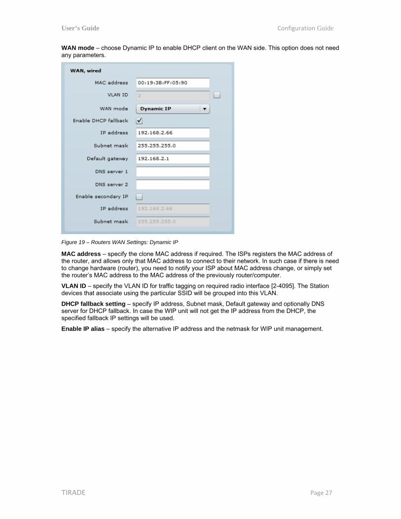
WAN mode – choose Dynamic IP to enable DHCP client on the WAN side. This option does not need any parameters.
Figure 19 – Routers WAN Settings: Dynamic IP
MAC address – specify the clone MAC address if required. The ISPs registers the MAC address of the router, and allows only that MAC address to connect to their network. In such case if there is need to change hardware (router), you need to notify your ISP about MAC address change, or simply set the router’s MAC address to the MAC address of the previously router/computer.
VLAN ID – specify the VLAN ID for traffic tagging on required radio interface [2-4095]. The Station devices that associate using the particular SSID will be grouped into this VLAN.
DHCP fallback setting – specify IP address, Subnet mask, Default gateway and optionally DNS server for DHCP fallback. In case the WIP unit will not get the IP address from the DHCP, the specified fallback IP settings will be used.
Enable IP alias – specify the alternative IP address and the netmask for WIP unit management.

User’s Guide Configuration Guide
TIRADE Page 28
WAN mode – choose PPPoE to configure WAN interface to connect to an ISP via a PPPoE:
Figure 20 – Routers WAN Settings: PPPoE
MAC address – specify the clone MAC address if required. The ISPs registers the MAC address of the router, and allows only that MAC address to connect to their network. In such case if there is need to change hardware (router), you need to notify your ISP about MAC address change, or simply set the router’s MAC address to the MAC address of the previously router/computer.
VLAN ID – specify the VLAN ID for traffic tagging on required radio interface [2-4095]. The Station devices that associate using the particular SSID will be grouped into this VLAN.
User name – specify the user name for PPPoE.
Password – specify the password for PPPoE.
MTU – specify the MTU (Maximum Transmission Unit). The default value is 1500 bytes.
DNS settings – allows selecting if automatically assigned or alternative DNS servers should be used.
Enable IP alias – specify the alternative IP address and the netmask for WIP unit management.
LAN Network Settings
LAN network settings includes settings related to the LAN interface
Figure 21 – Router LAN Settings

User’s Guide Configuration Guide
TIRADE Page 29
IP address – specify the IP address of the device LAN interface.
Subnet mask – specify the subnet mask of the device LAN interface.
LAN DHCP Settings
DHCP mode – choose disabled to disable DHCP on LAN interface.
Figure 22 – Router LAN Settings: DHCP Disabled
DHCP mode – choose relay to enable DHCP relay. The DHCP relay forwards DHCP messages between subnets with different sublayer broadcast domains.
Figure 23 – Router LAN Settings: DHCP Relay
DHCP mode – choose server to enable DHCP server on LAN interface.
Figure 24 – Router LAN Settings: DHCP Server
IP address from – specify the starting IP address of the DHCP address pool.
IP address to – specify the ending IP address of DHCP address pool.
Subnet mask – specify the subnet mask.
Default gateway – specify DHCP gateway IP address.
Lease time – specify the expiration time in seconds for the IP address assigned by the DHCP server.
DNS server – specify the DNS server IP address.

User’s Guide Configuration Guide
TIRADE Page 30
Wireless The Wireless tab is divided in three sections: Basic, Security and Advanced configuration sections. The Basic section contains all parameters that required to configure in order have working wireless link. Security section is used to select authentication and encryption settings. Advanced section contains parameters allowing optimizing the link capacity.
Before changing radio settings manually verify that your settings will comply with local government regulations. At all times, it is the responsibility of the end-user to ensure that the installation complies with local radio regulations.
The WIP device can operate in four wireless modes: Access Point, Station, Station WDS, iPoll Access Point and iPoll Station.
Figure 25 – Device Wireless Operating Mode
Depending on the wireless operation mode selection some of the displayed configuration parameters will differ (e.g. security or advanced wireless settings).
Wireless mode – select wireless operation mode:
Access Point (auto WDS)) – enables the WIP radio function as an access point. When in AP mode, wireless clients can see the AP broadcast and associate to it if settings are configured correctly.
Station – sets the radio to run in client mode. In this mode wireless station does not broadcast an SSID and clients cannot connect to it. Station mode allows the WIP radio to connect to other radios functioning as an AP.
Station WDS – a wireless station will communicate with access point in WDS mode. Station WDS mode enables packet forwarding at layer 2 level.
iPoll Access Point – enables WIP radio function as access point for point-to-multipoint solution. The iPoll Access Point accepts only iPoll Station requests.
iPoll Station – enables WIP radio function as wireless station for point-to-multipoint solution. The iPoll Station can establish a link only with iPoll Access point.
Be sure that both ends of the link have the appropriate wireless mode, otherwise the connection will be not established (e.g. iPoll Station is able to establish a connection only with iPoll AP).
Country – choose from the drop-down list the country in which the WIP will operate. The channel list, transmit power limits, IEEE 802.11 mode will be adjusted according to the regulations of the selected country.

User’s Guide Configuration Guide
TIRADE Page 31
Wireless Mode: Access Point (auto WDS) Use Basic Wireless Settings to setup radio interface of the device.
Figure 26 – Access Point Wireless Settings
Basic Wireless Settings
SSID – specify the SSID of the wireless network device.
Broadcast SSID – enables or disables the broadcasting of the SSID for AP.
IEEE mode – specify the wireless network mode.
Channel width – The default channel bandwidth for 802.11 radio is 20MHz. The 802.11n allow channel bonding in such way the total channel width becomes 40MHz.
Channel – select the channel from the drop-down list or option Auto for autochannel. Automatic channel selection allows Access Point to select a channel which is not used by any other wireless device or, if there are no free channels available - to select a channel which is least occupied.
Channel list – select the channels to create a channel list for autochannel.
User’s Guide Configuration Guide
TIRADE Page 32
Security Settings
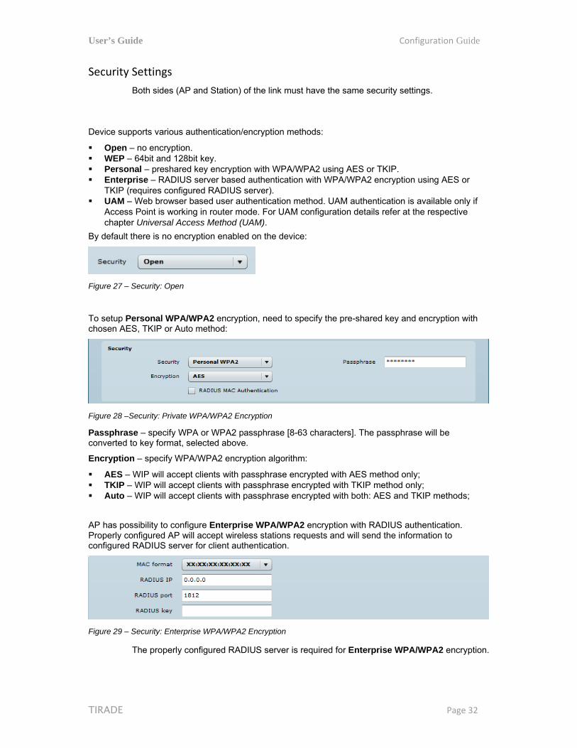
Both sides (AP and Station) of the link must have the same security settings.
Device supports various authentication/encryption methods:
Open – no encryption. WEP – 64bit and 128bit key. Personal – preshared key encryption with WPA/WPA2 using AES or TKIP. Enterprise – RADIUS server based authentication with WPA/WPA2 encryption using AES or
TKIP (requires configured RADIUS server). UAM – Web browser based user authentication method. UAM authentication is available only if
Access Point is working in router mode. For UAM configuration details refer at the respective chapter Universal Access Method (UAM).
By default there is no encryption enabled on the device:
Figure 27 – Security: Open
To setup Personal WPA/WPA2 encryption, need to specify the pre-shared key and encryption with chosen AES, TKIP or Auto method:
Figure 28 –Security: Private WPA/WPA2 Encryption
Passphrase – specify WPA or WPA2 passphrase [8-63 characters]. The passphrase will be converted to key format, selected above.
Encryption – specify WPA/WPA2 encryption algorithm:
AES – WIP will accept clients with passphrase encrypted with AES method only; TKIP – WIP will accept clients with passphrase encrypted with TKIP method only; Auto – WIP will accept clients with passphrase encrypted with both: AES and TKIP methods;
AP has possibility to configure Enterprise WPA/WPA2 encryption with RADIUS authentication. Properly configured AP will accept wireless stations requests and will send the information to configured RADIUS server for client authentication.
Figure 29 – Security: Enterprise WPA/WPA2 Encryption
The properly configured RADIUS server is required for Enterprise WPA/WPA2 encryption.
User’s Guide Configuration Guide
TIRADE Page 33
Encryption – specify WPA/WPA2 encryption algorithm:
AES – AP will accept clients with passphrase encrypted with AES method; TKIP – AP will accept clients with passphrase encrypted with TKIP method; Auto – AP will accept clients with passphrase encrypted with both: AES and TKIP methods;
RADIUS authentication settings:
RADIUS IP – specify the IP address of the authentication RADIUS server where the authentication requests will be send to.
RADIUS port – specify the network port used to communicate with the RADIUS authentication server. Default: 1812 for authentication.
RADIUS key – specify the secret key of the authentication server [string]. The shared secret is used to encrypt data packets transmitted between RADIUS server and client.
Shared secrets must be the same on the RADIUS servers and the RADIUS client.
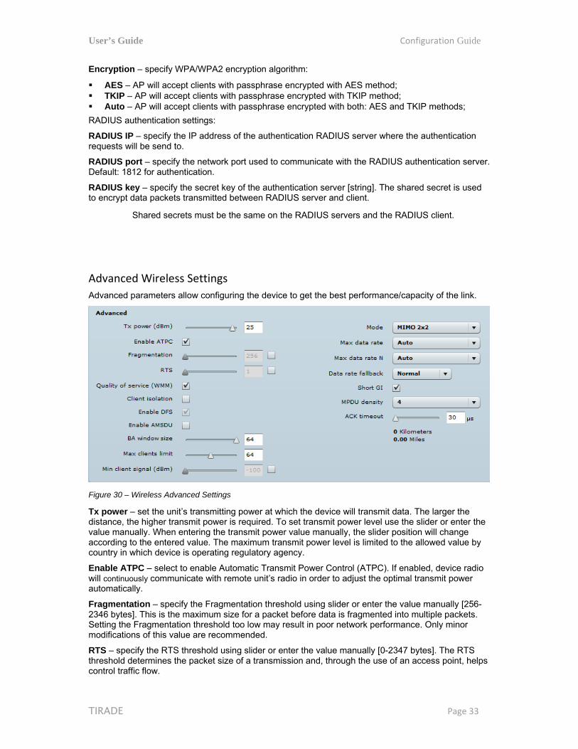
Advanced Wireless Settings
Advanced parameters allow configuring the device to get the best performance/capacity of the link.
Figure 30 – Wireless Advanced Settings
Tx power – set the unit’s transmitting power at which the device will transmit data. The larger the distance, the higher transmit power is required. To set transmit power level use the slider or enter the value manually. When entering the transmit power value manually, the slider position will change according to the entered value. The maximum transmit power level is limited to the allowed value by country in which device is operating regulatory agency.
Enable ATPC – select to enable Automatic Transmit Power Control (ATPC). If enabled, device radio will continuously communicate with remote unit’s radio in order to adjust the optimal transmit power automatically.
Fragmentation – specify the Fragmentation threshold using slider or enter the value manually [256-2346 bytes]. This is the maximum size for a packet before data is fragmented into multiple packets. Setting the Fragmentation threshold too low may result in poor network performance. Only minor modifications of this value are recommended.
RTS – specify the RTS threshold using slider or enter the value manually [0-2347 bytes]. The RTS threshold determines the packet size of a transmission and, through the use of an access point, helps control traffic flow.
User’s Guide Configuration Guide
TIRADE Page 34
Quality of service (WMM) – enable to support quality of service for traffic prioritizing.
Client isolation – select to enable the layer 2 isolation that blocks clients from communicating with each other. Client isolations is available only in Access Point (auto WDS) mode.
Enable DFS – select to enable radar detection. With enabled DFS, WIP unit monitors the operating frequency for radar signals. If radar signals are detected on the channel, the WIP unit randomly selects a different channel.
Enable AMSDU – enable the AMSDU packet aggregation. If enabled, the maximum size of the 802.11 MAC frames will be increased.
Mode – choose the AP antenna operating mode:
SISO – single input single output. The device will use only one antenna for data transfer. The antenna will be chosen automatically.
MIMO – multiple input multiple output. The device will use two antennas for data transfer (two simultaneous streams).
Max data rate – choose the maximum data rate in Mbps at which should transmit packets. The WIP will attempts to transmit data at the highest data rate set. If there will be an interference encountered, the WIP will step down to the highest rate that allows data transmission.
Max data rate N – choose the data rates in Mbps at which should transmit packets for the selected 802.11n mode. The WIP will attempts to transmit data at the highest data rate set. If there will be an interference encountered, the WIP will step down to the highest rate that allows data transmission.
Disable data rate fallback – when this option is selected, the constant Max data rate will be set without a step back to the next highest data rate for WIP data transmission.
Short GI – enable short guard interval. If selected, then 400ns value will be used, else 800ns.
MPDU density – define minimum time between PPDU’s.
ACK timeout – specify the ACK timeout using slider or enter the value manually. Ack timeout can be entered by defining the link distance or specifying time value. Too low value of the ACK timeout will give very low throughput. A high value may slow down the link in noisy environment. A low value is far worse than a value slightly too high. ACK Timeout value should be tuned to the optimal value for the maximum link throughput.

User’s Guide Configuration Guide
TIRADE Page 35
Wireless Mode: Station
Station WDS has the same wireless settings.
The Station wireless settings a bit differ from the Access Point’s settings: there is possibility to scan SSID of the surrounding APs and choose the required one.
Use Wireless Settings to setup radio interface of the device.
Figure 31 – Station Basic Wireless Settings
Basic Wireless Settings
SSID – specify the SSID of the wireless network device.
Scan – click this button to scan for surrounding wireless networks. Found network SSID’s will be available in drop down menu.
IEEE mode – specify the wireless network mode.
Channel width - The default channel bandwidth for 802.11 radio is 20MHz. The 802.11n allow channel bonding in such way the total channel width becomes 40MHz.
Security Settings
Both sides (AP and Station) of the link must have the same security settings.
Device supports various authentication/encryption methods:
Open – no encryption. WEP – 64bit and 128bit key. Personal – preshared key encryption with WPA/WPA2 using AES or TKIP. Enterprise – RADIUS server based authentication with WPA/WPA2 encryption using AES or
TKIP (requires configured RADIUS server).
By default there is no encryption enabled on the device:
Figure 32 – Security: Open
WEP encryption can be either 64bit or 128bit:
Figure 33 – Security: WEP Encryption

User’s Guide Configuration Guide
TIRADE Page 36
WEP passkey – specify the passkey, for the chosen WEP security:
For WEP 64bit encryption – 5 HEX pairs (e.g. aa:bb:cc:dd:ee), or 5 ASCII characters (e.g. abcde);
For WEP 128bit encryption – 13 HEX pairs (e.g. aa:bb:cc:dd:ee:ff:gg:hh:00:11:22:33:44), or 13 ASCII characters (e.g. abcdefghijklm);
Personal WPA/WPA2 encryption must be specified with the pre-shared key, encrypted with chosen AES or TKIP method (Auto mode on Station is not available):
Figure 34 –Security: Private WPA/WPA2 Encryption
Passphrase – specify the WPA or WPA2 passphrase [8-63 characters]. The passphrase will be converted to key format, selected above.
Encryption – specify the encryption algorithm:
AES – passphrase encrypted with AES method. TKIP – passphrase encrypted with TKIP method.
WIP has possibility to use Enterprise WPA/WPA2 encryption with RADIUS authentication. Station will send requests to AP, which will redirect authentication parameters to required RADIUS server.
Figure 35 – Security: Enterprise WPA/WPA2 Encryption
Encryption – choose WPA/WPA2 encryption type:
AES – data encrypted with AES method; TKIP – data encrypted with TKIP method;
EAP method – choose EAP method:
EAP-TTLS-MSCHAPv2 PEAP/ MSCHAPv2
Identity – specify the identity of the authentication to the RADIUS server.
Password – specify the password of the authentication to the RADIUS server.
Identity and Password on the WIP must match the identity and password running on the RADIUS server's user list.

User’s Guide Configuration Guide
TIRADE Page 37
Advanced Wireless Settings
Advanced parameters allow configuring the device to get the best performance/capacity of the link.
Figure 36 – Wireless Advanced Settings
Tx power – set the unit’s transmitting power at which the device will transmit data. The larger the distance, the higher transmit power is required. To set transmit power level use the slider or enter the value manually. When entering the transmit power value manually, the slider position will change according to the entered value. The maximum transmit power level is limited to the allowed value by country in which device is operating regulatory agency.
Enable ATPC – select to enable Automatic Transmit Power Control (ATPC). If enabled, device radio will continuously communicate with remote unit’s radio in order to adjust the optimal transmit power automatically.
Fragmentation – specify the Fragmentation threshold using slider or enter the value manually [256-2346 bytes]. This is the maximum size for a packet before data is fragmented into multiple packets. Setting the Fragmentation threshold too low may result in poor network performance. Only minor modifications of this value are recommended.
RTS – specify the RTS threshold using slider or enter the value manually [0-2347 bytes]. The RTS threshold determines the packet size of a transmission and, through the use of an access point, helps control traffic flow.
Quality of service (WMM) – enable to support quality of service for traffic prioritizing.
Enable DFS – select to enable radar detection. With enabled DFS, WIP unit monitors the operating frequency for radar signals. If radar signals are detected on the channel, the WIP unit randomly selects a different channel.
Enable AMSDU – enable the AMSDU packet aggregation. If enabled, the maximum size of the 802.11 MAC frames will be increased.
Mode – choose the AP antenna operating mode:
SISO – single input single output. The device will use only one antenna for data transfer. The antenna will be chosen automatically.
MIMO – multiple input multiple output. The device will use two antennas for data transfer (two simultaneous streams).
Max data rate – choose the maximum data rate in Mbps at which should transmit packets. The WIP will attempts to transmit data at the highest data rate set. If there will be an interference encountered, the WIP will step down to the highest rate that allows data transmission.
Max data rate N – choose the data rates in Mbps at which should transmit packets for the selected 802.11n mode. The WIP will attempts to transmit data at the highest data rate set. If there will be an interference encountered, the WIP will step down to the highest rate that allows data transmission.
Disable data rate fallback – when this option is selected, the constant Max data rate will be set without a step back to the next highest data rate for WIP data transmission.
User’s Guide Configuration Guide
TIRADE Page 38
Short GI – enable short guard interval. If selected, then 400ns value will be used, else 800ns.
MPDU density – define minimum time between PPDU’s.
ACK timeout – specify the ACK timeout using slider or enter the value manually. Ack timeout can be entered by defining the link distance or specifying time value. Too low value of the ACK timeout will give very low throughput. A high value may slow down the link in noisy environment. A low value is far worse than a value slightly too high. ACK Timeout value should be tuned to the optimal value for the maximum link throughput.
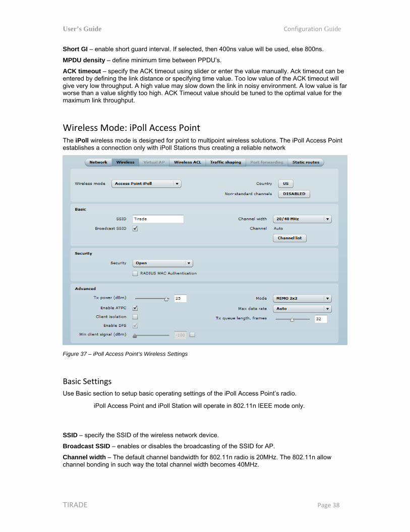
Wireless Mode: iPoll Access Point The iPoll wireless mode is designed for point to multipoint wireless solutions. The iPoll Access Point establishes a connection only with iPoll Stations thus creating a reliable network
Figure 37 – iPoll Access Point’s Wireless Settings
Basic Settings
Use Basic section to setup basic operating settings of the iPoll Access Point’s radio.
iPoll Access Point and iPoll Station will operate in 802.11n IEEE mode only.
SSID – specify the SSID of the wireless network device.
Broadcast SSID – enables or disables the broadcasting of the SSID for AP.
Channel width – The default channel bandwidth for 802.11n radio is 20MHz. The 802.11n allow channel bonding in such way the total channel width becomes 40MHz.

User’s Guide Configuration Guide
TIRADE Page 39
Channel – select the channel from the drop-down list or option Auto for autochannel. Automatic channel selection allows iPoll Access Point to select a channel which is not used by any other wireless device or, if there are no free channels available - to select a channel which is least occupied.
Channel list – select the channels to create a channel list for autochannel.
Security Settings
Both sides (iPoll Access Point and iPoll Station) of the link must have the same security settings.
The WIP device working, in iPoll Access Point wireless mode, supports authentication/encryption methods listed below:
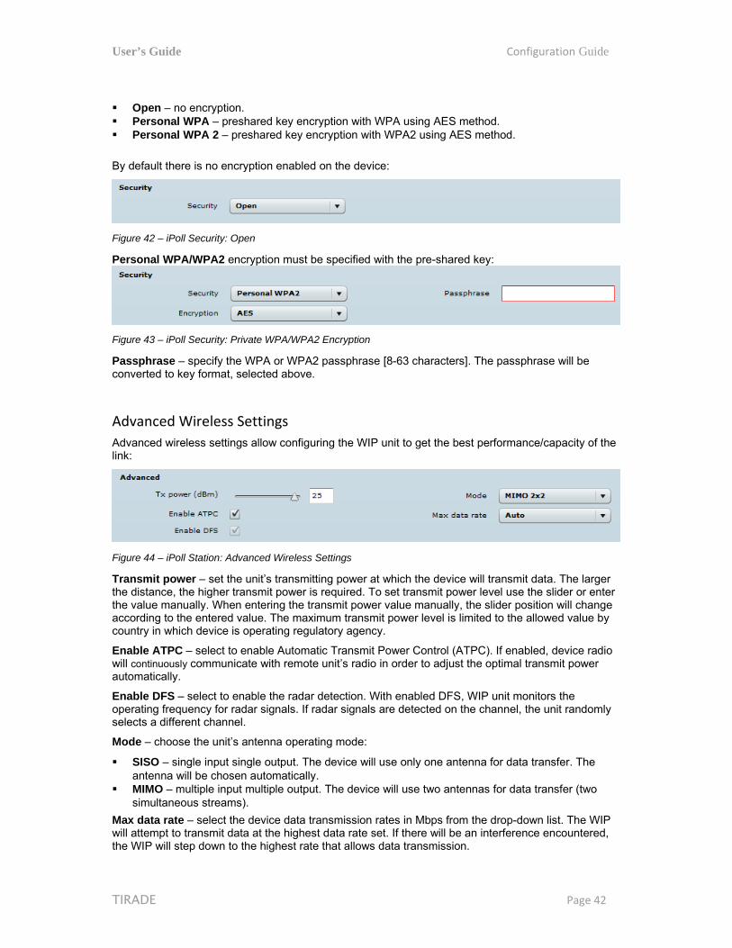
Open – no encryption. Personal WPA – preshared key encryption with WPA using AES method. Personal WPA 2 – preshared key encryption with WPA2 using AES method.
By default there is no encryption enabled on the device:
Figure 38 – iPoll Security: Open
Personal WPA/WPA2 encryption must be specified with the pre-shared key:
Figure 39 – iPoll Security: Private WPA/WPA2 Encryption
Passphrase – specify the WPA or WPA2 passphrase [8-63 characters]. The passphrase will be converted to key format, selected above.
User’s Guide Configuration Guide
TIRADE Page 40
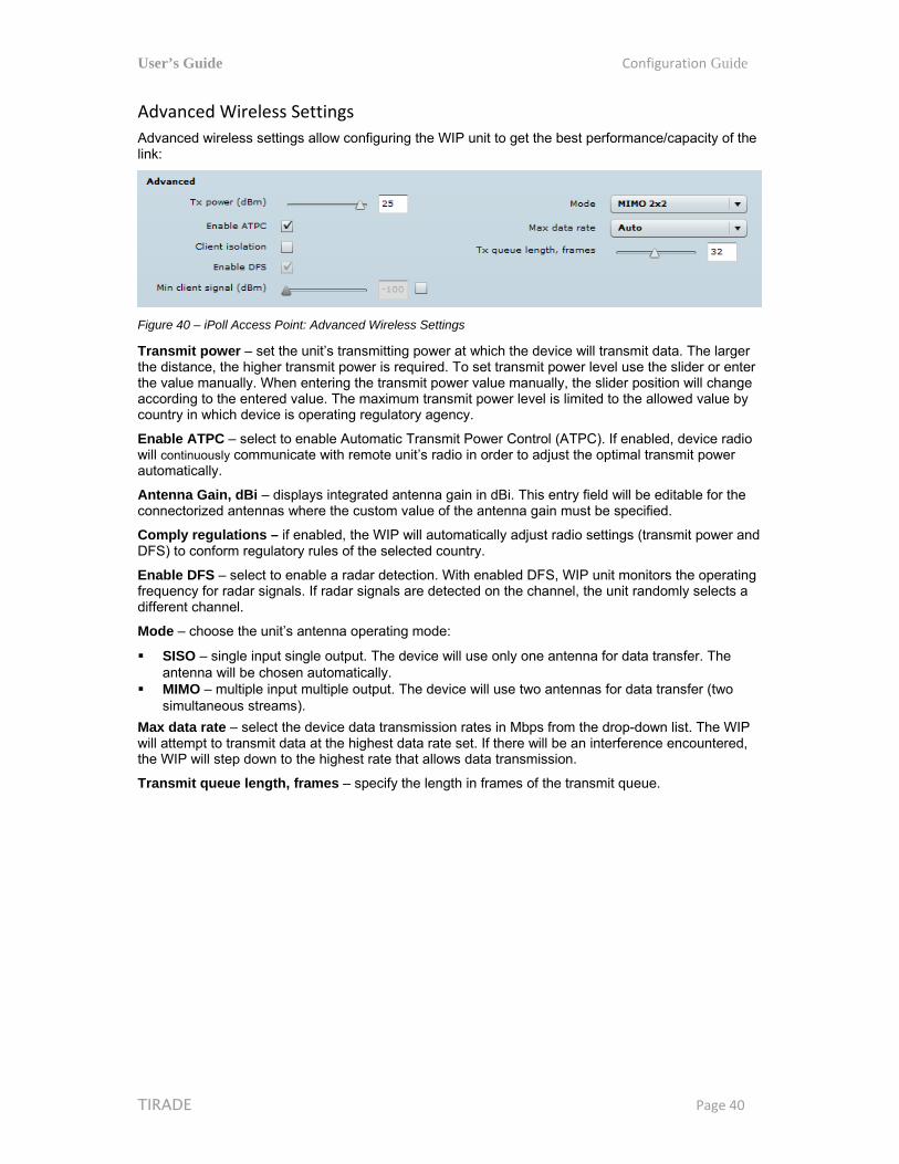
Advanced Wireless Settings
Advanced wireless settings allow configuring the WIP unit to get the best performance/capacity of the link:
Figure 40 – iPoll Access Point: Advanced Wireless Settings
Transmit power – set the unit’s transmitting power at which the device will transmit data. The larger the distance, the higher transmit power is required. To set transmit power level use the slider or enter the value manually. When entering the transmit power value manually, the slider position will change according to the entered value. The maximum transmit power level is limited to the allowed value by country in which device is operating regulatory agency.
Enable ATPC – select to enable Automatic Transmit Power Control (ATPC). If enabled, device radio will continuously communicate with remote unit’s radio in order to adjust the optimal transmit power automatically.
Antenna Gain, dBi – displays integrated antenna gain in dBi. This entry field will be editable for the connectorized antennas where the custom value of the antenna gain must be specified.
Comply regulations – if enabled, the WIP will automatically adjust radio settings (transmit power and DFS) to conform regulatory rules of the selected country.
Enable DFS – select to enable a radar detection. With enabled DFS, WIP unit monitors the operating frequency for radar signals. If radar signals are detected on the channel, the unit randomly selects a different channel.
Mode – choose the unit’s antenna operating mode:
SISO – single input single output. The device will use only one antenna for data transfer. The antenna will be chosen automatically.
MIMO – multiple input multiple output. The device will use two antennas for data transfer (two simultaneous streams).
Max data rate – select the device data transmission rates in Mbps from the drop-down list. The WIP will attempt to transmit data at the highest data rate set. If there will be an interference encountered, the WIP will step down to the highest rate that allows data transmission.
Transmit queue length, frames – specify the length in frames of the transmit queue.

User’s Guide Configuration Guide
TIRADE Page 41
Wireless Mode: iPoll Station The iPoll Station is a wireless client mode which can connect to the iPoll Access Points.
Figure 41 – iPoll Station's Wireless Settings
Basic Settings
Use this section to setup basic operating settings of the iPoll Station radio.
iPoll Access Point and iPoll Station will operate in 802.11n IEEE mode only.
SSID – specify the SSID of the wireless network device manually, or use Scan functionality.
Scan – click this button to scan for surrounding iPoll Access Points. Found network SSID’s will be available in drop down menu.
Channel width – The default channel bandwidth for 802.11 N radio is 20/40MHz. The 802.11n allow channel bonding in such way the total channel width becomes 40MHz.
Security Settings
Both sides (iPoll Access Point and iPoll Station) of the link must have the same security settings.
The WIP device working, in iPoll Station wireless mode, supports authentication/encryption methods listed below:
User’s Guide Configuration Guide
TIRADE Page 42
Open – no encryption. Personal WPA – preshared key encryption with WPA using AES method. Personal WPA 2 – preshared key encryption with WPA2 using AES method.
By default there is no encryption enabled on the device:
Figure 42 – iPoll Security: Open
Personal WPA/WPA2 encryption must be specified with the pre-shared key:
Figure 43 – iPoll Security: Private WPA/WPA2 Encryption
Passphrase – specify the WPA or WPA2 passphrase [8-63 characters]. The passphrase will be converted to key format, selected above.
Advanced Wireless Settings
Advanced wireless settings allow configuring the WIP unit to get the best performance/capacity of the link:
Figure 44 – iPoll Station: Advanced Wireless Settings
Transmit power – set the unit’s transmitting power at which the device will transmit data. The larger the distance, the higher transmit power is required. To set transmit power level use the slider or enter the value manually. When entering the transmit power value manually, the slider position will change according to the entered value. The maximum transmit power level is limited to the allowed value by country in which device is operating regulatory agency.
Enable ATPC – select to enable Automatic Transmit Power Control (ATPC). If enabled, device radio will continuously communicate with remote unit’s radio in order to adjust the optimal transmit power automatically.
Enable DFS – select to enable the radar detection. With enabled DFS, WIP unit monitors the operating frequency for radar signals. If radar signals are detected on the channel, the unit randomly selects a different channel.
Mode – choose the unit’s antenna operating mode:
SISO – single input single output. The device will use only one antenna for data transfer. The antenna will be chosen automatically.
MIMO – multiple input multiple output. The device will use two antennas for data transfer (two simultaneous streams).
Max data rate – select the device data transmission rates in Mbps from the drop-down list. The WIP will attempt to transmit data at the highest data rate set. If there will be an interference encountered, the WIP will step down to the highest rate that allows data transmission.

User’s Guide Configuration Guide
TIRADE Page 43
Virtual AP
Virtual AP functionality is available only in Access Point (auto WDS) wireless mode.
Use the Configuration | Virtual AP page to configure to create up to 3 additional Virtual AP interfaces. The Virtual AP defines a logical wireless network, and the WIP can be configured to provide additional 3 wireless networks on each device radio. All the VAPs may be active at the same time meaning that client devices can associate to the WIP using any of the VAP SSID.
The Virtual AP table displays a summary of all virtual radio interfaces running on the WIP:
Figure 45 – VAP Table
To create a new Virtual AP, click on + button to add new entry on the VAP table, then select this entry and specify required parameters:
Figure 46 – VAP Settings:
SSID – specify the unique name for the VAP [string].
Broadcast SSID – when this option is selected the particular SSID is visible during network scans on a wireless station. When unselected, the VAP SSID is not visible and not broadcasted to wireless stations.
Quality of service (WMM) – enable to support quality of service for prioritizing traffic.
User isolation – enable the user Layer 2 isolation. The Layer 2 isolation blocks the wireless clients from communicating with each other.
Each VAP security is configured by default as an “open system”, which broadcasts a beacon signal including the configured SSID. For more secure network choose one of the security mechanisms for each VAP interface.
Security – choose the wireless security and encryption method from the drop-down list (for detailed security configuration, refer to the respective section Access Point (auto WDS) Security Settings).
Open – no encryption. WEP – 64bit and 128bit key. Personal – preshared key encryption with WPA/WPA2 using AES or TKIP. Enterprise – RADIUS server based authentication with WPA/WPA2 encryption using AES or
TKIP (requires configured RADIUS server). UAM – Web browser based user authentication method. UAM authentication is available only if

User’s Guide Configuration Guide
TIRADE Page 44
Access Point is working in router mode. For UAM configuration details refer at the respective chapter Universal Access Method (UAM).
Wireless clients must be able to process the WPA or WPA2 information element and respond with a specific security configuration.
Wireless ACL
Wireless ACL is active only in Access Point (auto WDS) and iPoll Access Point wireless mode.
Access Control provides the ability to limit associations wirelessly based on MAC address to an AP by creating an Access Control List (ACL).
Figure 47 – Wireless ACL Configuration
Policy – define the policy:
Open – no rules applied Allow MAC in the list – only listed MAC clients can connect to the AP (white list). Deny MAC in the list – only listed MAC clients can NOT connect to the AP (black list).
To add new rule, press the “+” button.
To remove the rule, first select the rule then press the “–” button.
To edit the rule double click on the field.
Traffic Shaping Use Traffic Shaping to control download or upload bandwidth in order to optimize or guarantee performance. There are two methods to control network traffic:
Limit all traffic – limits overall WIP upload and download traffic. Limit per IP traffic – limits upload and download traffic for a specified IP addresses.
Figure 48 – Traffic Shaping Configuration

User’s Guide Configuration Guide
TIRADE Page 45
Limit all traffic
Enable download shaping – select to enable limitation of the download traffic.
Download limit, kbps – specify the maximum download (from wireless interface to Ethernet interface) bandwidth value in Kbps.
Download burst, kbytes – specify the download burst size in kbytes.
Enable upload shaping – select to enable limitation of the upload traffic.
Upload limit, kbps – specify the maximum upload (from Ethernet interface to wireless interface) bandwidth value in Kbps.
Upload burst, kbytes – specify the upload burst size in kbytes
Limit per IP traffic
Use + button to create new traffic limitation rules
Figure 49 – Traffic Shaping: Per IP Limitation
IP address – specify IP address for which the traffic will be limited.
Down rate, kbps – specify the maximum download (from wireless interface to Ethernet interface) bandwidth value in Kbps.
Down burst, kbytes – specify the download burst size in kbytes.
UP rate, kbps – specify the maximum upload (from Ethernet interface to wireless interface) bandwidth value in Kbps.
UP burst, kbytes – specify the download burst size in kbytes
Port Forwarding
Port forwarding is active only in Router network mode..
Port Forwarding, UPnP and DMZ is effective only if NAT is enabled.
The Port forwarding section gives the ability to pass traffic behind an interface that has NAT enabled. For instance if the unit is in router mode with NAT enabled on the WAN interface, no devices on the outside of the WAN interface can see any private IPs on the LAN side of the unit. By using port forwarding or DMZ it is possible to pass traffic through to these private IP addresses.

User’s Guide Configuration Guide
TIRADE Page 46
Figure 50 – Port Forwarding Configuration
Enable UPnP – select to enable UPnP (Universal Plug and Play connectivity) service. The UPnP enables WIP communicate with other network devices automatically opening required ports, without manual intervention.
Enable DMZ – select to enable DMZ. DMZ opens all TCP/UDP ports to particular IP address. It allows setting up servers behind the WIP. The feature is used commonly for setting up VoIP or Multi-Media servers.
Public port – specify the port that will be accessed externally using the public IP address.
Private host – specify the IP address behind NAT that public traffic will get forwarded to.
Private port – specify the listening port on private computer behind NAT.
Protocol – select type of forwarding traffic: TCP or UDP.
User’s Guide Configuration Guide
TIRADE Page 47
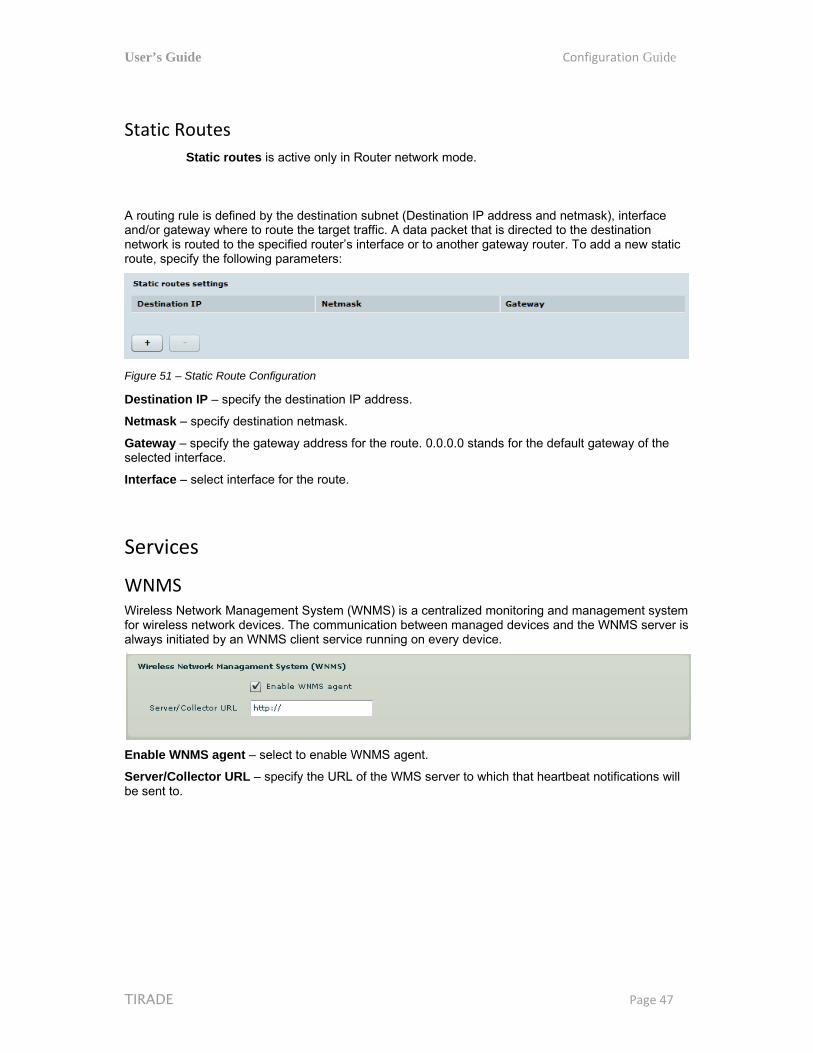
Static Routes
Static routes is active only in Router network mode.
A routing rule is defined by the destination subnet (Destination IP address and netmask), interface and/or gateway where to route the target traffic. A data packet that is directed to the destination network is routed to the specified router’s interface or to another gateway router. To add a new static route, specify the following parameters:
Figure 51 – Static Route Configuration
Destination IP – specify the destination IP address.
Netmask – specify destination netmask.
Gateway – specify the gateway address for the route. 0.0.0.0 stands for the default gateway of the selected interface.
Interface – select interface for the route.
Services
WNMS Wireless Network Management System (WNMS) is a centralized monitoring and management system for wireless network devices. The communication between managed devices and the WNMS server is always initiated by an WNMS client service running on every device.
Enable WNMS agent – select to enable WNMS agent.
Server/Collector URL – specify the URL of the WMS server to which that heartbeat notifications will be sent to.

User’s Guide Configuration Guide
TIRADE Page 48
System alerts The device is able to send external alerts when there are system errors. The alerts can be sent via SNMP Traps or/and SMTP notifications.
Figure 52 – Device Alerts
Enable alerts – select to enable alert notifications on the system.
System check interval, s – specify interval in seconds at which the device will send notifications of unexpected system behavior.
System alerts:
Wireless link status change – system will send notification on Wireless link status change.
Ethernet link status change – system will send notification on Ethernet link status change.
RSSI level lower than – system will send notification when RSSI reach value lower than specified. Default: 25
Noise level greater than – system will send notification when signal noise will reach value greater than specified. Default: -60 dBm.
RX drop greater than – system will send notification when percent of RX dropped packets become higher than specified value. Default: 250 packets per seconds.
TX retry greater than – system will send notification when percent of TX retries becomes higher than specified value. Default: 250 packets per seconds.
Device reboot – system will send notification about unexpected or administrator initiated device reboot.
Figure 53 – Device Alerts: SNMP Traps and SMTP Configuration
User’s Guide Configuration Guide
TIRADE Page 49
SNMP Traps Settings
Manager address – specify the IP address or hostname of SNMP Trap receiver.
Manager port – specify the port number of the Trap receiver. Default port number is 162.
Trap community - specify the SNMP community string. This community string acts as password between SNMP manager and device by default Trap community string is "public".
Use inform – select to wait for an acknowledgment from SNMP manager that trap was received.
Retry count – specifies maximum number of times to resend an inform request [1-10]. Default: 5.
Retry timeout – specifies number in seconds to wait for an acknowledgment before resending request [1-10]. Default: 1.
SMTP Settings
Server address – specify the IP address or hostname of the networked SMTP server.
Server port – specify the SMTP Port Number is the port number used by the networked SMTP server. By default the port number is 25.
Source e-mail address – specify the e-mail address that will be used by the device.
Destination e-mail address – specify the e-mail address where the device will send the alert messages.
E-mail notification interval – specify interval in seconds at which the e-mail notification will be sent from the device [0-86400]. If 0 specified, then device will send an e-mail notification immediately after unexpected system behavior.
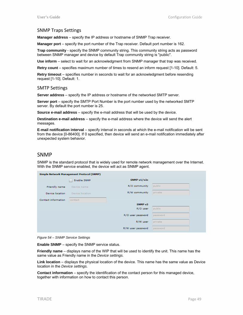
SNMP SNMP is the standard protocol that is widely used for remote network management over the Internet. With the SNMP service enabled, the device will act as SNMP agent.
Figure 54 – SNMP Service Settings
Enable SNMP – specify the SNMP service status.
Friendly name – displays name of the WIP that will be used to identify the unit. This name has the same value as Friendly name in the Device settings.
Link location – displays the physical location of the device. This name has the same value as Device location in the Device settings.
Contact information – specify the identification of the contact person for this managed device, together with information on how to contact this person.

User’s Guide Configuration Guide
TIRADE Page 50
R/O community – specify the read-only community name for SNMP version 1 and version 2c. The read-only community allows a manager to read values, but denies any attempt to change values.
R/O user – specify the user name for read-only SNMPv3 access. The read-only community allows a manager to read values, but denies any attempt to change values.
R/O user password – specify the password for read-only SNMPv3 access [string].
Clock/NTP Use this section to manage the system time and date on the device automatically, using the Network Time Protocol (NTP), or manually, by setting the time and date on the device.
The NTP (Network Time Protocol) client synchronizes the clock of the device with the defined time server. Choose NTP from the configuration menu, select your location time zone and enter NTP server in order to use the NTP service.
Figure 55 – Device Clock: NTP Configuration
Configuration – choose the system clock configuration mode [NTP/Manual].
Timezone – select the timezone. Time zone should be specified as a difference between local time and GMT time.
Save last known time – select to recall the timestamp that was saved on last reboot. When NTP is enabled, this option will set system clock to last reboot time if no NTP servers are available.
NTP server – specify the trusted NTP server IP or hostname for synchronizing time with [IP address].
To adjust the clock settings manually, choose the configuration mode as Manual and specify the following settings:
Figure 56 – Device Clock: Manual Configuration
Configuration – choose the system clock configuration mode [NTP/Manual].
Timezone – select the timezone. Time zone should be specified as a difference between local time and GMT time.
Save last known time – select to recall the timestamp that was saved on last reboot.
Date – specify the new date value in format MM/DD/YYYY
Time – specify the time in format hh:mm.
SSH Use this menu to manage access to the device via SSH port:

User’s Guide Configuration Guide
TIRADE Page 51
Figure 57 – SSH Port Configuration
Enabled – enable or disable SSH access to device.
Port – the SSH service port. By default SSH port is 22.
HTTP Use this menu to control HTTP connection on device web management:
Figure 58 – HTTP Settings
Enable management through HTTP – select tis option to enable or disable HTTP access to the device management.
Port – specify HTTP port. Standard HTTP port is 80.
HTTPS connection via the standard port 8080 is always enabled.

User’s Guide Configuration Guide
TIRADE Page 52
System
Administration
For security reasons it is recommended to change the default administrator username and password as soon as possible.
System menu allows you to manage main system settings and perform main system actions (reboot, restore configuration, etc.). The section is divided into further three sections: Device settings, Account settings and system functions.
Figure 59 – Device Administration Settings
Device settings
Friendly name – specify name of the WIP that will be used to identify the unit.
Device location – describe the location of the device [maximum 255 ASCII characters].
Longitude – specify the longitude coordinates of the device [specific decimal format, e.q. 54.869446].
Latitude – specify the latitude coordinates of the device [specific decimal format, e.q. 23.891058]. Both coordinates helps indicate accurate location of the device.
Account settings
The Administrative Account menu is for changing the administrator’s password.
Default administrator logon settings are: Username: admin Password: admin01
Username – change the administrator’s username.
Old password – enter the old administrator password.
New password – enter the new administrator password for user authentication.
Verify password – re-enter the new password to verify its accuracy.
The only way to gain access to the web management if you forget the administrator password is to reset the unit to factory default settings.

User’s Guide Configuration Guide
TIRADE Page 53
System functions
Reboot device – reboot device with the last saved configuration.
Reset device to factory defaults – click to restore unit's factory configuration.
Resetting the device is an irreversible process. Current configuration and the administrator password will be set back to the factory default.
Download troubleshooting file – click to download the troubleshooting file. The troubleshooting file contains valuable information about device configuration, routes, log files, command outputs, etc. When using the troubleshooting file, the device quickly gathers troubleshooting information automatically, rather than requiring you to gather each piece of information manually. This is helpful for submitting problems to the support team.
Backup configuration file – click to save the current configuration file. The saved configuration file is useful to restore a configuration in case of a device misconfiguration or to upload a standard configuration to multiple devices without the need to manually configure each device through the web interface.
Restore configuration from file – click to upload an existing configuration file to the device.
Log Use the log tab to configure device to view or save log messages to the local or remote server using standard syslog facility:
Figure 60 – Device System Log
View system log – click to view current trace messages. The system log viewer utility provides debug information about the system services and protocols. If the device's malfunction occurs recorded messages can help operators to locate misconfiguration and system errors.
Message level – specify system's message tracing level. The level determines the importance of the message and the volume of messages generated by the device. The levels are in increased importance order [emergency, alert, critical, error, warning, notice, information, debug]. Default: info.
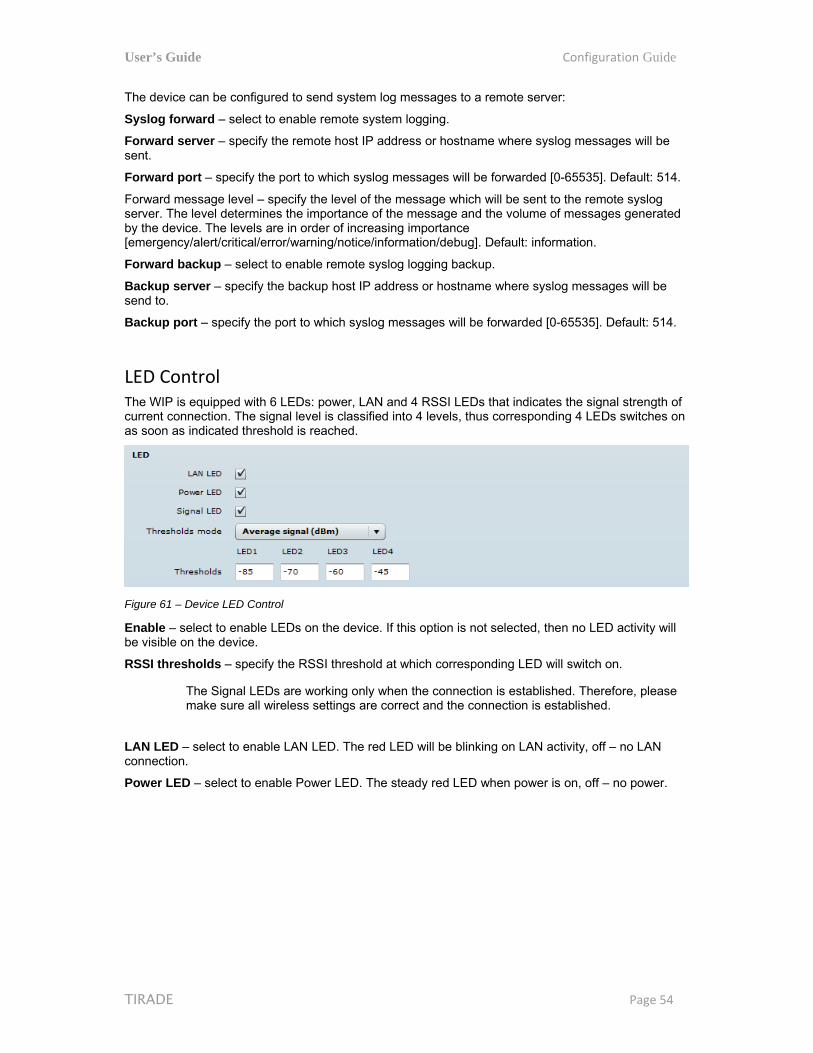
User’s Guide Configuration Guide
TIRADE Page 54
The device can be configured to send system log messages to a remote server:
Syslog forward – select to enable remote system logging.
Forward server – specify the remote host IP address or hostname where syslog messages will be sent.
Forward port – specify the port to which syslog messages will be forwarded [0-65535]. Default: 514.
Forward message level – specify the level of the message which will be sent to the remote syslog server. The level determines the importance of the message and the volume of messages generated by the device. The levels are in order of increasing importance [emergency/alert/critical/error/warning/notice/information/debug]. Default: information.
Forward backup – select to enable remote syslog logging backup.
Backup server – specify the backup host IP address or hostname where syslog messages will be send to.
Backup port – specify the port to which syslog messages will be forwarded [0-65535]. Default: 514.
LED Control The WIP is equipped with 6 LEDs: power, LAN and 4 RSSI LEDs that indicates the signal strength of current connection. The signal level is classified into 4 levels, thus corresponding 4 LEDs switches on as soon as indicated threshold is reached.
Figure 61 – Device LED Control
Enable – select to enable LEDs on the device. If this option is not selected, then no LED activity will be visible on the device.
RSSI thresholds – specify the RSSI threshold at which corresponding LED will switch on.
The Signal LEDs are working only when the connection is established. Therefore, please make sure all wireless settings are correct and the connection is established.
LAN LED – select to enable LAN LED. The red LED will be blinking on LAN activity, off – no LAN connection.
Power LED – select to enable Power LED. The steady red LED when power is on, off – no power.
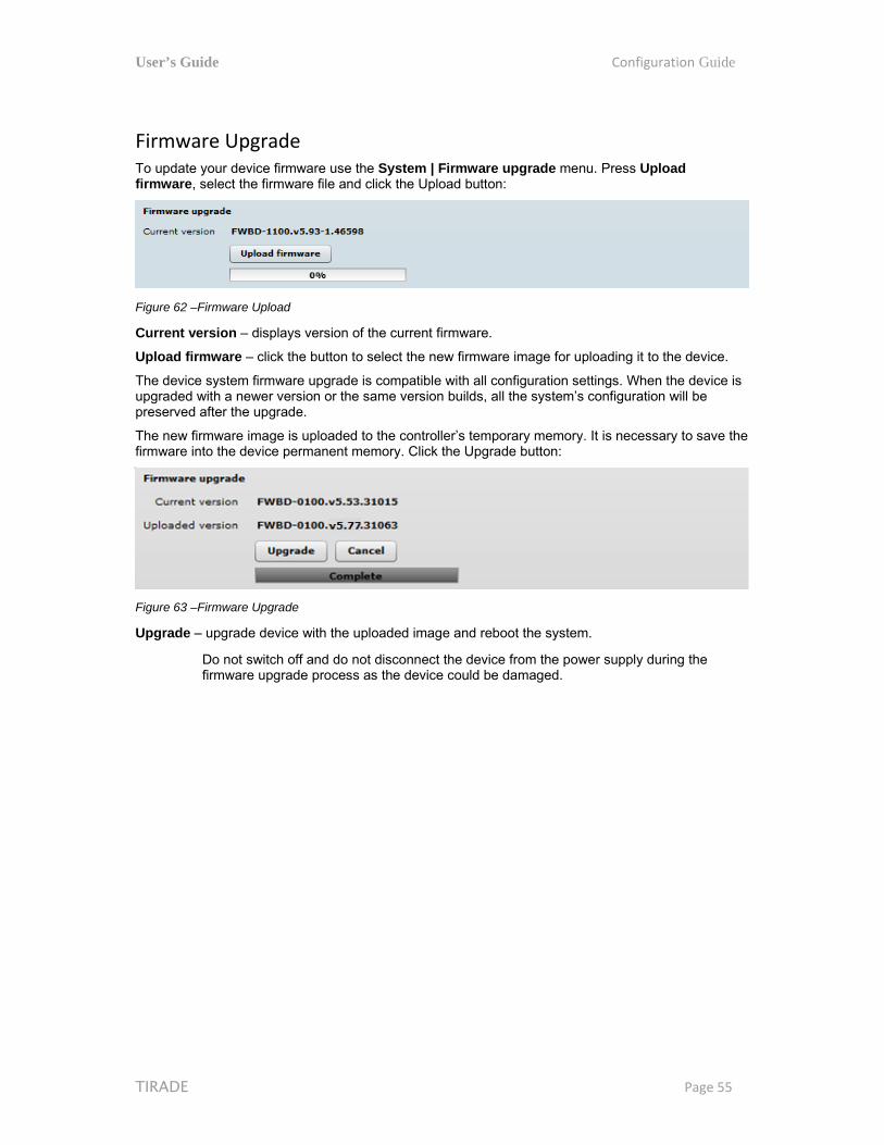
User’s Guide Configuration Guide
TIRADE Page 55
Firmware Upgrade To update your device firmware use the System | Firmware upgrade menu. Press Upload firmware, select the firmware file and click the Upload button:
Figure 62 –Firmware Upload
Current version – displays version of the current firmware.
Upload firmware – click the button to select the new firmware image for uploading it to the device.
The device system firmware upgrade is compatible with all configuration settings. When the device is upgraded with a newer version or the same version builds, all the system’s configuration will be preserved after the upgrade.
The new firmware image is uploaded to the controller’s temporary memory. It is necessary to save the firmware into the device permanent memory. Click the Upgrade button:
Figure 63 –Firmware Upgrade
Upgrade – upgrade device with the uploaded image and reboot the system.
Do not switch off and do not disconnect the device from the power supply during the firmware upgrade process as the device could be damaged.

User’s Guide Configuration Guide
TIRADE Page 56
Tools
Antenna Alignment The Antenna Alignment tool measures signal quality between the Station and AP. For best results during the antenna alignment test, turn off all wireless networking devices within range of the device except the device(s) with which you are trying to align the antenna. Watch the constantly updated display in the Alignment Test window as you adjust the antenna.
Figure 64 – Antenna Alignment
Start – press this button to start antenna alignment.
Stop – press this button to stop antenna alignment.
Average – if this option selected, the graph will display the average RSSI of both antennas.
Site Survey The Site Survey tool shows overview information for wireless networks in a local geographic area. Using this test, an administrator can scan for working access points, check their operating channels, encryption and see signal/noise levels.
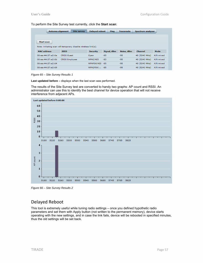
User’s Guide Configuration Guide
TIRADE Page 57
To perform the Site Survey test currently, click the Start scan:
Figure 65 – Site Survey Results 1
Last updated before – displays when the last scan was performed.
The results of the Site Survey test are converted to handy two graphs: AP count and RSSI. An administrator can use this to identify the best channel for device operation that will not receive interference from adjacent APs.
Figure 66 – Site Survey Results 2
Delayed Reboot This tool is extremely useful while tuning radio settings – once you defined hypothetic radio parameters and set them with Apply button (not written to the permanent memory), device starts operating with the new settings, and in case the link fails, device will be rebooted in specified minutes, thus the old settings will be set back.
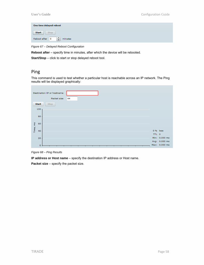
User’s Guide Configuration Guide
TIRADE Page 58
Figure 67 – Delayed Reboot Configuration
Reboot after – specify time in minutes, after which the device will be rebooted.
Start/Stop – click to start or stop delayed reboot tool.
Ping This command is used to test whether a particular host is reachable across an IP network. The Ping results will be displayed graphically:
Figure 68 – Ping Results
IP address or Host name – specify the destination IP address or Host name.
Packet size – specify the packet size.

User’s Guide Configuration Guide
TIRADE Page 59
Traceroute This tool is a route-tracing utility used to determine the path that an IP packet has taken to reach a destination. This is useful when trying to find out why destination is unreachable, as you will be able to see where the connection fails.
Figure 69 – Traceroute Results
Destination IP or Hostname – specify hostname or IP address of the target host.
Max Hops –Specifies the maximum number of hops to search for target.
Start/Stop – click to start or stop traceroute tool.
Spectrum Analyzer The Spectrum analyzer test displays detailed information about signal level of each WIP unit’s antenna on each available frequency. This enables administrator choose the best available frequency/channel for the unit operation. The frequency list depends on the Country at which the unit is operating, and chosen channel width.
Do not use the Spectrum analyzer on the remote unit of the link, as the connection to the device will be lost during the test.
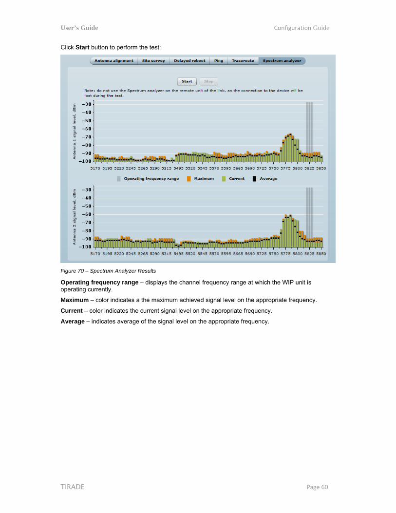
User’s Guide Configuration Guide
TIRADE Page 60
Click Start button to perform the test:
Figure 70 – Spectrum Analyzer Results
Operating frequency range – displays the channel frequency range at which the WIP unit is operating currently.
Maximum – color indicates a the maximum achieved signal level on the appropriate frequency.
Current – color indicates the current signal level on the appropriate frequency.
Average – indicates average of the signal level on the appropriate frequency.
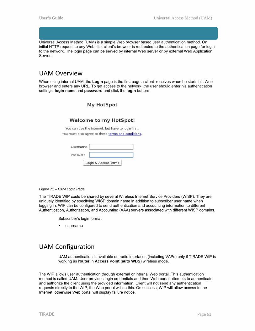
User’s Guide Universal Access Method (UAM)
TIRADE Page 61
Universal Access Method (UAM) Universal Access Method (UAM) is a simple Web browser based user authentication method. On initial HTTP request to any Web site, client’s browser is redirected to the authentication page for login to the network. The login page can be served by internal Web server or by external Web Application Server.
UAM Overview When using internal UAM, the Login page is the first page a client receives when he starts his Web browser and enters any URL. To get access to the network, the user should enter his authentication settings: login name and password and click the login button:
Figure 71 – UAM Login Page
The TIRADE WIP could be shared by several Wireless Internet Service Providers (WISP). They are uniquely identified by specifying WISP domain name in addition to subscriber user name when logging in. WIP can be configured to send authentication and accounting information to different Authentication, Authorization, and Accounting (AAA) servers associated with different WISP domains.
Subscriber’s login format:
username
UAM Configuration
UAM authentication is available on radio interfaces (including VAPs) only if TIRADE WIP is working as router in Access Point (auto WDS) wireless mode.
The WIP allows user authentication through external or internal Web portal. This authentication method is called UAM. User provides login credentials and then Web portal attempts to authenticate and authorize the client using the provided information. Client will not send any authentication requests directly to the WIP, the Web portal will do this. On success, WIP will allow access to the Internet; otherwise Web portal will display failure notice.

User’s Guide Universal Access Method (UAM)
TIRADE Page 62
Use Security section on Wireless or VAP (depending on the interface on which the UAM will be configured) page for UAM configuration: choose the security option UAM:
Figure 72 – UAM Settings
RADIUS Settings
NAS ID – specify the NAS identifier.
RADIUS server 1 – specify the name or IP address of the primary RADIUS server.
RADIUS server 2 – specify the name or IP address of the secondary RADIUS server.
RADIUS Secret – specify the RADIUS shared secret.
RADIUS authentication port – specify the UDP port number to use for radius authentication requests, default 1812
RADIUS accounting port – specify the UDP port number to use for radius accounting requests, default 1813
RADIUS WEB page type – choose the authentication Web portal type:
Internal – use the built in authentication Web page. If selected, then when a users first tries to access the Internet, they will be blocked, and re-directed to the built-in login page. The logon data will be sent to the Radius Server for authentication.
External – specify the external authentication Web page URL and settings. If selected, then when a user first tries to access the Internet, they will be blocked, and re-directed to the URL specified below.
Custom internal – upload a customized internal page.
Use HTTPS – enable to use the HTTPS protocol for connection and authentication.
Key – upload a PEM formatted private key file. Certificate – upload a PEM formatted certificate file.

User’s Guide Universal Access Method (UAM)
TIRADE Page 63
WISPr Settings
WISPr location name – specify the WISPr location name.
Operator name – specify the operator’s name
Network name – specify the network name
ISO country code – specify the country code in ISO standard.
E.164 country code – specify the country code in E.164 standard.
E.164 area code – specify the area code in E.164 standard.
WISPr default max bandwidth – specify the default bandwidth limitation for clients. Note that if the external RADIUS server has traffic limitations preconfigured, then RADIUS overrides these settings.
Download, kbps – specify max download bandwidth in kbps.
Upload, kbps – specify the max upload bandwidth in kbps.
Interface IP address – specify the LAN interface IP address. Note that LAN settings on Network menu will be disabled if UAM is enabled.
DHCP settings – specify the dynamic IP settings for the connected users:
Network – specify the network for IP address pool.
Subnet mask – specify the subnet mask for the DHCP.
DNS server – specify the primary and the secondary DNS servers.
Data encryption settings – choose the data encryption method:
Open – no encryption. Personal WPA – preshared key encryption with WPA using AES method. Personal WPA 2 – preshared key encryption with WPA2 using AES method.
White/Black List The white and black access lists control user access to Web content through the WIP. The unauthenticated users will be allowed to access sites from white list while access to the sites from black list will be denied even for authenticated users.
Figure 73 – White List and Black List
Use “+” sign to add new entry to the list, and “–” sign to remove required one.
White list
Host/IP address – specify the IP addresses or hosts for free access even for unauthenticated users.
Notes – add a description for the specified host or IP address.
Black list
Host/IP address – specify the IP addresses or hosts that will be not accessible even for the authenticated users.
Notes – a description for the specified host or IP address.

User’s Guide Appendix
TIRADE Page 64
Appendix
A) Resetting Device to Factory Defaults Device has the capability of being reset to defaults by pinging the device with a certain packet size when the radio is booting. During the startup of the device, when the drivers of the Ethernet interfaces are loaded, the discovery daemon is started. The daemon suspends startup process for 3 seconds and waits for ICMP "echo request" packet of length 369 bytes. If the packet received, the discoveryd resets the device to default configuration.
It is recommended to connect PC to the device via switch, as depending on PC OS settings, the ARP table might be flushed during wired link status change (connecting the device that will be reset).
Steps to reset to default settings:
Step 1. Power off the WIP device.
Step 2. Obtain the device MAC address.
Step 3. Connect a PC to the same physical subnet as the device.
Step 4. Execute 'arp -s' command to assign the IP address (IP address should be from the same subnet as PC) to the device MAC address:
arp -s <IP address to assign> <device MAC address>
Note that syntax of MAC address differs depending on OS:
Linux OS: AA:BB:CC:DD:EE:FF Windows OS: AA-BB-CC-DD-EE-FF
Step 5. Start ping the device:
For Linux users: ping <IP address> -s 369
For Windows users: ping <IP address> -l 369 -t -w 0.2
Step 6. Power up WIP device and wait about 30sec or more (depending on device hardware).
Step 7. Stop pinging the device, and let the device boot as usual. The device should start up with factory default settings.
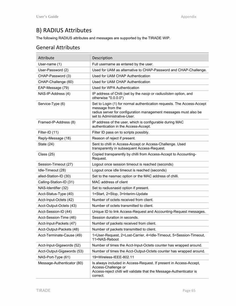
User’s Guide Appendix
TIRADE Page 65
B) RADIUS Attributes The following RADIUS attributes and messages are supported by the TIRADE WIP.
General Attributes
Attribute Description
User-name (1) Full username as entered by the user.
User-Password (2) Used for UAM as alternative to CHAP-Password and CHAP-Challenge.
CHAP-Password (3) Used for UAM CHAP Authentication
CHAP-Challenge (60) Used for UAM CHAP Authentication
EAP-Message (79) Used for WPA Authentication
NAS-IP-Address (4) IP address of Chilli (set by the nasip or radiuslisten option, and otherwise "0.0.0.0")
Service-Type (6) Set to Login (1) for normal authentication requests. The Access-Accept message from the radius server for configuration management messages must also be set to Administrative-User.
Framed-IP-Address (8) IP address of the user, which is configurable during MAC authentication in the Access-Accept.
Filter-ID (11) Filter ID pass on to scripts possibly.
Reply-Message (18) Reason of reject if present.
State (24) Sent to chilli in Access-Accept or Access-Challenge. Used transparently in subsequent Access-Request.
Class (25) Copied transparently by chilli from Access-Accept to Accounting-Request.
Session-Timeout (27) Logout once session timeout is reached (seconds)
Idle-Timeout (28) Logout once idle timeout is reached (seconds)
alled-Station-ID (30) Set to the nasmac option or the MAC address of chilli.
Calling-Station-ID (31) MAC address of client
NAS-Identifier (32) Set to radiusnasid option if present.
Acct-Status-Type (40) 1=Start, 2=Stop, 3=Interim-Update
Acct-Input-Octets (42) Number of octets received from client.
Acct-Output-Octets (43) Number of octets transmitted to client.
Acct-Session-ID (44) Unique ID to link Access-Request and Accounting-Request messages.
Acct-Session-Time (46) Session duration in seconds.
Acct-Input-Packets (47) Number of packets received from client.
Acct-Output-Packets (48) Number of packets transmitted to client.
Acct-Terminate-Cause (49) 1=User-Request, 2=Lost-Carrier, 4=Idle-Timeout, 5=Session-Timeout, 11=NAS-Reboot
Acct-Input-Gigawords (52) Number of times the Acct-Input-Octets counter has wrapped around.
Acct-Output-Gigawords (53) Number of times the Acct-Output-Octets counter has wrapped around.
NAS-Port-Type (61) 19=Wireless-IEEE-802.11
Message-Authenticator (80) Is always included in Access-Request. If present in Access-Accept, Access-Challenge or Access-reject chilli will validate that the Message-Authenticator is correct.
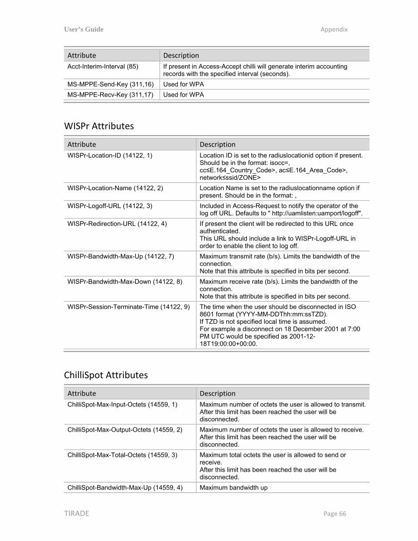
User’s Guide Appendix
TIRADE Page 66
Attribute Description
Acct-Interim-Interval (85) If present in Access-Accept chilli will generate interim accounting records with the specified interval (seconds).
MS-MPPE-Send-Key (311,16) Used for WPA
MS-MPPE-Recv-Key (311,17) Used for WPA
WISPr Attributes
Attribute Description
WISPr-Location-ID (14122, 1) Location ID is set to the radiuslocationid option if present. Should be in the format: isocc=, cc≤E.164_Country_Code>, ac≤E.164_Area_Code>, network≤ssid/ZONE>
WISPr-Location-Name (14122, 2) Location Name is set to the radiuslocationname option if present. Should be in the format: ,
WISPr-Logoff-URL (14122, 3) Included in Access-Request to notify the operator of the log off URL. Defaults to " http://uamlisten:uamport/logoff".
WISPr-Redirection-URL (14122, 4) If present the client will be redirected to this URL once authenticated. This URL should include a link to WISPr-Logoff-URL in order to enable the client to log off.
WISPr-Bandwidth-Max-Up (14122, 7) Maximum transmit rate (b/s). Limits the bandwidth of the connection. Note that this attribute is specified in bits per second.
WISPr-Bandwidth-Max-Down (14122, 8) Maximum receive rate (b/s). Limits the bandwidth of the connection. Note that this attribute is specified in bits per second.
WISPr-Session-Terminate-Time (14122, 9) The time when the user should be disconnected in ISO 8601 format (YYYY-MM-DDThh:mm:ssTZD). If TZD is not specified local time is assumed. For example a disconnect on 18 December 2001 at 7:00 PM UTC would be specified as 2001-12-18T19:00:00+00:00.
ChilliSpot Attributes
Attribute Description
ChilliSpot-Max-Input-Octets (14559, 1) Maximum number of octets the user is allowed to transmit. After this limit has been reached the user will be disconnected.
ChilliSpot-Max-Output-Octets (14559, 2) Maximum number of octets the user is allowed to receive. After this limit has been reached the user will be disconnected.
ChilliSpot-Max-Total-Octets (14559, 3) Maximum total octets the user is allowed to send or receive. After this limit has been reached the user will be disconnected.
ChilliSpot-Bandwidth-Max-Up (14559, 4) Maximum bandwidth up

User’s Guide Appendix
TIRADE Page 67
Attribute Description
ChilliSpot-Bandwidth-Max-Down (14559, 5) Maximum bandwidth down
ChilliSpot-Config (14559, 6) Configurations passed between chilli and back-end as name value pairs
ChilliSpot-Lang (14559, 7) Language selected in user interface
ChilliSpot-Version (14559, 8) Version of Chilli sending this AccessRequest

User’s Guide Index
TIRADE Page 68
Index
A abbrevations, 5 access point, 29 access point WDS, 29 ACK timeout, 33, 36 ACL, 5, 37 AES, 5, 30, 33, 37 alerts, 41
SNMP traps, 42 antenna alignment, 50 antenna mode
MIMO, 33, 35 SISO, 32, 35
AP, 5, 7, 10, 13, 14, 19
B black list, 37 broadcast
SSID, 30 broadcast SSID, 10, 36
C clock, 43 configuration backup, 47 configuration restore, 47 CPE, 5
D data rates, 33, 35 default administrator login, 9 default IP, 9 default login, 46 default settings, 9, 12 DFS, 32 DHCP, 5, 28
client, 16, 25 server, 13
DMZ, 39 dynamic IP, 13
E EAP, 5, 34 Ethernet link duplex, 22 Ethernet link speed, 22
F firmware upgrade, 49 fragmentation threshold, 32, 35
G GMT, 5, 44
I IEEE, 5, 10, 13, 30, 33
802.11n, 7 802.a/b/g, 7
initial AP setup, 9 initial Station setup, 12 IP, 5 IP settings
dynamic IP, 23, 25 static IP, 23, 25
isolation L2 user isolation, 36
ISP, 5
L LAN, 5, 10, 16 latitude, 46 layer 2 isolation, 32 LED, 5, 48 Limit per IP traffic, 37 longitude, 46
M
MAC, 5 management VLAN, 23 MIMO, 6 MPDU density, 33, 36 MSCHAPv2, 6, 35
N NAT, 6, 10, 16, 39 network mode
bridge, 16, 22 router, 10, 16, 22, 38, 39
NTP, 43, 44
P PC, 6, 9 PDA, 6 PEAP, 6, 35 port, 39 port forwarding, 22, 39 PPPoE, 16, 26 PSK, 6
Q QoS, 6, 32, 35

User’s Guide Index
TIRADE Page 69
Quality of service (WMM), 36
R radar detection, 32 RADIUS, 31, 34 RADIUS server, 30, 34, 37 reboot device, 47 reset to defaults
ping reset, 54 web management, 47
RSSI, 6 RTS threshold, 32, 35
S scan SSID, 33, 50 SGI, 33, 36 SISO, 6 site survey, 50 SMTP, 6, 42 SNMP, 6 SNMP service, 43 SSID, 6, 10, 13, 30, 33, 36 Static IP, 16 static routes, 22, 39 station, 7, 19 Station, 29 Station WDS, 29 syslog, 47
T TCP, 6, 39 timestamp, 44 timezone, 44 TKIP, 6, 30, 33, 34, 37 traffic limitation, 37 traffic shaping, 37 troubleshooting file, 47 TTLS, 6 TX power, 32, 35
U UDP, 6, 39 UPnP, 39
V Virtual AP, 36 VLAN, 6 VoIP, 6
W
WAN, 10, 16 WDS, 6 web management, 17, 19 WEP, 6, 30, 33, 37
white list, 37 WLAN, 6 WNMS, 41 WPA, 6, 30, 33, 37 WPA2, 6, 30, 33, 37

User’s Guide Index
TIRADE Page 70


![Point-to-Multipoint and Multipoint-to-Multipoint · PDF filedefined by IEEE 802.1Qay [2] is representative carrier Ethernet . Abstract — We have implemented point-to-multipoint (PtMP)](https://img.dokumen.tips/doc/110x75/5a75c0147f8b9a4b538cb6cd/point-to-multipoint-and-multipoint-to-multipoint-defined-by-ieee-8021qay.jpg)