Embed Size (px)
Citation preview

Winpact Bench-Top Fermenter
Instruction ManualFS-01-B Series(Single wall dish bottom
vessel)
Version: V2.4Revised on: 2012.09.13

Table of Contents
Section 1 Packing list .................................................................................. .. 3
Section 2 Warning ................................................................................. ........ 5
2.2Safety Information ................................................................................... . 5
2.3Environmental Conditions ................................................................... ..... 5
2.4Avoiding Electrical Shock ........................................................................ . 6
2.5Avoiding Damage to the Instrument ....................................................... .. 6
2.6Equipment Operation ........................................................................... .... 6
Section 3 Warranty Agreements and Customer Service ............................ 8
3.1Warranty agreements ............................................................................. .. 8
3.2Return policy ......................................................................................... ... 8
Section 4 Introduction ................................................................................ . 10
Section 5 Specifications ................................................................... .......... 11
Section 6 Delivery & Installation .......................................................... ...... 28
6.1Unpacking and Parts Check ................................................................ ... 28
6.2Installing the fermentation system, space requirements ........................ 28
2

6.3Utility Requirements ............................................................................. .. 28
Section 7 Component description .................................................... ......... 30
7.1Control unit layout .............................................................................. .... 30
7.2Temperature control system ................................................................... 36
7.3Culture vessel .................................................................................. ...... 38
Section 8 Control interface ...................................................................... ... 38
1.1Monitor ................................................................................................ ... 39
8.2Pump ................................................................................................... ... 40
8.3Control ........................................................................................... ........ 42
8.4Setting .................................................................................................... 43
8.5Chart ................................................................................................. ..... 55
8.6Calibration .............................................................................................. 56
8.7Maint. ................................................................................................ ..... 58
8.8Help ..................................................................................................... ... 59
Section 1 Operating the system .............................................................. ... 60
1.1Preparation and connection of the control unit ....................................... 60
9.2Prepare the Culture Vessel and Accessories ................................... ...... 61
9.3Prepare the Fermentation Run ............................................................. .. 63
Section 10 Remote control setting ......................................................... .. 66
3

10.1Connecting your PC to the Winpact controller ..................................... 66
10.2Controlling the Winpact system on your PC ......................................... 68
Section 11 Cleaning and Maintenance ...................................................... . 72
11.1Vessel Cleaning ................................................................................. ... 72
11.2Control Station Cleaning ............................................................. ......... 72
11.3DO electrode information and maintenance .................................... .... 72
11.4pH probe information and maintenance ..................................... ......... 73
4

Section 1 Packing list
When the unit arrives, please make sure that all items are included in the package. Use the following packing list to check the items. If an item is missing, please contact local major science representative or [email protected]
Item Description Qty
1 Controller 1
2 Culture vessel (Single wall dish bottom) 1
DO/pH probe adaptor 2
10mm blind Stopper (Only for 5L, 7L, 10L vessel) 3
3 Brushless motor 1
Accessories
4 pH probe (225mm for 3L; 325mm for 5L,7L,10L) 1
5 pH probe cable 1
6 DO probe (220mm for 3L; 320mm for 5L,7L,10) 1
7 DO probe cable 1
8 Temp. probe 1
9 PT-100 Temp. probe cable 1
5

10 Antifoam probe cable 1
11 Power cord (EU x1, US x1) 1
12 Winpact instruction manual 1
Start-up kit
13 250 ml glass bottle (includes 2 ports Stainless Steel Connecting set)
4
14 500 ml glass bottle (includes 2 ports Stainless Steel Connecting set)
1
15 45 mm 0.2mm Autoclavable disc type air filter , 10 each/pk 1
16 Stainless Steel Connecting Tube, 15 ea/pk 1
17 Handy Burner 1
18 Silicon tubing Clamp, 12 ea/pk 1
19 #16 (inner diameter – 3.2mm) silicon tube – 25 ft 1
20 2mm Hex Wrench 1
21 12mm and 14mm Double Open-End Wrench 1
22 Philips (+) Screwdriver 1
6

Signed by: Date:
Winpact is liable for all missing or damaged parts / accessories within 7 days after customer received this instrument package. Please contact Major Science immediately regarding this issue. If no response within such time period from consignee party, that will be consignee party’s whole responsibility.
7

Section 2 Warning
This equipment has been tested and verified to comply with safety limits. These limits are designed to provide reasonable protection against harmful interference when the equipment is operated in a commercial environment. This equipment may generate, use, and radiate radio frequency energy, and if not installed and used in accordance with the instruction manual, may cause harmful interference with radio communications. Operation of this equipment in a residential area is likely to cause harmful interference in which case the user will be required to correct the interference at their expense. Changes or modifications not expressly approved by the party responsible for compliance could void the user’s authority to operate the equipment. It is strongly recommended that the user carefully read the following prints before operating any equipment.
8

1.A.A.1. Read and follow the manual instructions thoroughly.
1.A.A.2. Do not alter the equipment. Failure to adhere to these directions could result in personal and/or laboratory hazards, as well as invalidate equipment warranty.
1.A.A.3. Use a properly grounded electrical outlet of correct voltage and current handling capacity.
1.A.A.4. Disconnect from power supply before maintenance and servicing. Refer servicing to qualified personnel.
1.A.A.5. In the event that solution is accidentally spilled into the instrument, disconnect grounded plug and the user must carry out appropriate decontamination. Replace damaged parts.
1.A.A.6. Do not use in the presence of flammable or combustible material; fire or explosion may result. This device contains components that can ignite such materials.
1.A.A.7. Refer maintenance and servicing to qualified personnel.
1.A.A.8. Ensure that the system is connected to electrical service according to local and national electrical codes. Failure to properly connect may create a fire or shock hazard.
1.A.A.9. Ensure the use of appropriate materials and correct operation to avoid possible hazards of explosion, implosion or release of toxic or flammable gases arising from the heated materials.
9

1.A.A.10. Handle the culture vessel with cares to prevent any damages or crashes to the glass vessel, especially before and after autoclave / sterilization.
1.A.A.11. Always use the supplied handle or appropriate protection to handle culture vessel in order to prevent against heat burning your hands, especially after autoclave/sterilization.
ATTENTION: Hot surface!
2.2 Safety Information
Use high levels of precaution when using any electrical device. Before connecting the electric supply, check to see if the supply voltage is within the range stated on the rating label, and see to it that the device be seated firmly. Place the unit in a safe and dry location, it MUST NOT touch any surrounding objects. Follow the safety precautions for chemicals/dangerous materials, and hot surfaces (after autoclave/sterilization). If needed, contact a qualified service representative or [email protected].
2.3 Environmental Conditions
Ensure the instrument is installed and operated strictly under the following conditions:
10

3.A.A.1. Indoor use only
3.A.A.2. ≤95% RH
3.A.A.3. 75 kPa – 106 kPa
3.A.A.4. Altitude must not exceed 2000 meters
3.A.A.5. Ambient to 40°C operating temperature
3.A.A.6. Pollution degree: 2
3.A.A.7. Mains supply voltage fluctuations up to ±10% of the normal voltage
2.4 Avoiding Electrical Shock
Follow the guidelines below to ensure safe operation of the unit.The Bench Top Programmable Fermentation System has been designed for use with shielded wires thus minimizing any potential shock hazard to the user. Major Science recommends against the use of unshielded wires.
11

1.A.A.1. Dry out for a period of time and restored to NORMAL CONDITION before operation.
4.A.A.1. NEVER connect or disconnect wires leading from the power jacks when the red indicator light on the Start/Stop key is on or when “RUNNING” is displayed on the screen.
4.A.A.2. WAIT at least 5 seconds after stopping a run before handling output leads or connected apparatus.
4.A.A.3. ALWAYS make sure that your hands, work area, and instruments are clean and dry before making any connections or operating the power supply.
4.A.A.4. ONLY connect the power cord to a properly grounded AC outlet.
12

2.5 Avoiding Damage to the Instrument
5.A.A.1. Do not attempt to operate the device if damaged.
5.A.A.2. Protect this unit from physical damage, corrosive agents and extreme temperatures (direct sunlight etc).
5.A.A.3. For proper ventilation, leave at least 10 cm of space behind the instrument, and at least 5 cm of space on each side.
5.A.A.4. Do not operate the instrument in high humidity environments (> 95%), or where condensation may occur.
5.A.A.5. Before using any cleaning or decontamination method except those recommended by the manufacturer, users should check with the manufacturer that the proposed method will not damage the equipment.
2.6 Equipment Operation
6.A.A.1. Check that the culture and all the accessories are assembled well and not damaged before starting the autoclave and fermentation process.
6.A.A.2. Ensure all other associated instruments and equipment, such as the Autoclave and Cooling Water Bath are in normal condition and their specifications meet the fermentation process needs. These instruments and equipment must be operated according to their instruction manual. Furthermore, the assembly and connection between themselves and the fermentation system must be carried out correctly.
6.A.A.3. NEVER access any HAZARDOUS LIVE parts that violate International Biosafety Regulations.
13

6.A.A.4. When operating other fermentation system-associated instruments, use the same level of precaution to prevent potential damage and ensure the fermentation performance.
The symbols used on the Bench Top Programmable Fermentation System are explained below.
Indicates an area where a potential shock hazard may exist.Indicates a warning. Consult the manual to avoid possible personal injury or instrument damage.ATTENTION: Hot surface!
14

Section 3 Warranty Agreements and
Customer Service
3.1 Warranty agreements
Major Science warrants its products against defects in materials and workmanship, under normal service, for a period of 12 months from the shipping date to purchaser, unless other terms are agreed upon in writing. The date of reference is the date of the delivery, which must be evidenced by presenting the corresponding delivery confirmation.The guarantee is given against defects in manufacture and against malfunctioning, but not for parts subject to wear and tear (O-ring, seals, membrane filter), defects or damages caused by improper handling, or defects and malfunctions caused by corrosion (due to lack of resistance against solvents, etc., which are used for fermentation).
The warranty does not cover parts subject to wear and tear or damages caused by improper handling. In addition, it does not cover the following:
15

1.A.A.1. Corrosion/damage to the tubing clamps on the peristaltic pump, which is caused by contact with strong acid/base or chemicals
1.A.A.2. Damage to the fermenter controller, vessel and cables caused by negligence during installation or adjustment
1.A.A.3. All probes (pH, DO; excluding DO probe membrane) are covered by the warranty for six months starting from date of completion of installation
1.A.A.4. O-rings, mechanical seals and start-up kits components (silicone tubing, clamp, feeding bottles, etc.)
1.A.A.5. All glass parts are excluded from the warranty
Note: Before first use or use under specific environmental conditions in the laboratory and/or together with special nutrients or additional solutions, you must test the resistance of all parts.
Major Science’s obligation under this warranty is limited to repairing parts or providing replacement parts at no charge, which prove to be defective during the warranty period. A part shall be considered defective after inspection of Major Science’s technical staff. At Major Science’s option, we will repair or replace any defective part, which is returned to our facilities. The cost of shipping the repaired or replacement part will be borne by Major Science. Any unit where repair or modification has been performed by anyone other than Major Science or an appointed distributor/representative is no longer under warranty from the time the unit was modified.
3.2 Return policy
A local Major Science representative can repair defects and damages. Defective appliances can also be returned to a local Major Science
16

representative. It will be the customer’s liability to pay all carriage charges. The repairs will be carried out and charged in accordance with our terms of maintenance.
Note: Upon return, the equipment must be clean, in good hygienic condition and carefully packed. Contagious parts must be disinfected or sterilized, according to chemical, biological, biotechnological or genetic safety regulations. The sender has to prove compliance with corresponding safety regulations. The sender will be charged for repair or damages due to transport and for necessary cleaning and disinfection of any parts.
For returning any equipment, please notify your local major science representative or contact Major Science directly:
No. 37, Wuquan 5th Rd., Wugu Dist., New Taipei City 24888 Taiwan, R.O.C.TEL: 886-2-2298-1055FAX: 886-2-2299-7871
19959 Sea Gull Way, Saratoga, CA 95070, U.S.A.TEL:1-408-366-9866FAX:1-408-446-1107
E-mail: [email protected]
17

Section 4 Introduction
Winpact Scientific is a product brand under Major Science, an innovative, R&D-basedmanufacturer supplying a broad product portfolio to the life science market. Winpact provides a comprehensive and innovative line of cultivation products designed for different cell culture experiments and applications. It comes in a benchtop scale and has a large, color touch-screen panel with a user-friendly interface. Its distinctive functions include various programming operations to control the pump speed, pH levels, temperature, and more. Winpact Fermentation System is equipped with a full connection device to connect to any PC for real-time recording and control within the vessel
Features
-10”4 color touch screen & graphical user interface
-Ethernet remote control and data logging function
-Flexible optional device selections
-Storage program: Up to 59,994 programs for different kind of conditions
-Data storage: Up to 100 data files
-Data export interface: USB port
-Modular system for easy upgrade & maintenance
-Full accessory as a package
18

Section 5 Specifications
Single wall (Dish bottom)
Vessel Max. Working volume
3L 5L 7L 10L
Total volume(Liter
)
3.8 6.8 8.9 12.5
Inner diameter(m
m)
130 160 180 190
Inner height(mm)
310 365 370 430
Overall diameter(m
m)
200 230 250 270
Height without
condenser(mm)
520 570 580 630
Height with
condenser(mm)
640 640 650 700
Material Borosilicate glass / 316L stainless steel for headplate and all fittings
19

Control unit Control panel 10.4” Color Touch-screen Interface(Resolution: 800 x 600 pixels)
Communication port Remote control through Ethernet
Storage program Up to 59,994 programs for different kinds of condition
Data storage Up to 100 data files
Data storage interface
USB port
Cabinet material ABS front panel and painted iron housing
Dimension Footprint: 400 x 500 mm (W x D) ; Height: 740 mm
Rated voltage 110V or 220V ; 50/60 Hz
Aeration Inlet Gas Flow-meter
0, 1 – 10 LPM
0, 2 – 20 LPM
Sparger Orifice ring
Baffle Removable 316L stainless steel baffles
Temperature
Heating Built-in heat exchanger
Cooling Cooling coil valve
Range ℃ ℃5 above coolant up to 60
Probe Platinum RTD probe (Pt-100)
Control mode Programmable 15 steps PID controller
20

Agitation Drive Removable Top brushless motor
Speed Range 30 – 1200 rpm (3L~7L) ; 30-1000rpm (10L)
Impeller Three adjustable Rushton-type impellers (standard);Two Pitched-blade impellers (optional)
Control mode Programmable 15 steps PID controller
pH Range 2 -14 pH
Probe Gel-filled electrode; Autoclavable
Control mode PID, one point control with adjustable deadband
DO Range 0 – 200%
Probe Polarographic DO sensor; Autoclavable
Control mode PID; Cascade function to response toa. Increase or decrease agitation speedb. Oxygen Enrichment module (Optional)c. Gas Mixing Station module (Optional)Start substrate feeding program
ORP(Optional)
Transmitter -/+ 2000 mV
Resolution 1 mV
Probe Gel-filled electrode; Autoclavable
Foam Probe 316L stainless steel detector with insulated teflon tube; On/Off control
21

Peristaltic pump
Pump number Four built-in pumps; One external pump (Optional)
Motor type Precise stepping motor; minimum speed is 1 rpm
Speed range 0 – 65 rpm
Control mode Programmable 15 steps feeding control; Pump can be assigned for Acid, Base, Antifoam and Substrate
Exhaust Device type 316L Stainless steel condenser
Utility requirement
Power supply 100-120V 50/60 Hz or 210-230V 50/60 Hz with electrical safety cutoff switch
Water 2 Bar maximum (29 psi)
Air 1 Bar maximum, must be dry, oil-free and filtered
Autoclave For sterilization
22

Section 6 Delivery & Installation
6.1 Unpacking and Parts Check
Please pay attention to the following advice:
1.A.A.1. Carefully check the outer packaging, the packaging of the single components, as well as the parts themselves for damage.
Warning: Do not use culture vessel when damage is suspected. In such a case, the glass vessel might burst during sterilization in the autoclave.
1.A.A.2. Check if the delivery is complete. To prevent scratching, please handle with care when using sharp objects to unwrap the packaging.
1.A.A.3. Please use caution when loading or unloading to prevent damage due to collision.
1.A.A.4. When moving or positioning the controller, take care not to lift it by holding the peristaltic pump heads. They are not designed to be used as handles, and can be damaged by lifting a heavy load.
1.A.A.5. If parts are missing or damage occurs in transit, please inform your local Major Science representative.
23

6.2 Installing the fermentation system, space requirements
2.A.A.1. The system will require an area of approximately W x D = 1,500 x 600 mm (including the space for the culture vessel and the cooling circulating water bath)
2.A.A.2. You may vary the arrangement of the components according to the lengths of the connecting lines. It is recommended to consider some additional space for convenient handling of the equipment.
2.A.A.3. Use the (+) Screwdriver to open the back panel for gas pressure adjustment before first use (Screwdriver is provided in the standard package). Detailed instructions are given below.
6.3 Utility Requirements
3.A.A.1. Gas Source: the incoming gas must be reduced to at least 2 bar (29psi) before entering the air inlet (Fig. 1). If you are using an air compressor or a cylinder, please be sure to use an external regulator to reduce the gas pressure. The inlet gas must be further adjusted to 0.5 bar (approx. 7psi) using the built-in pressure gauge (Fig. 2), the back panel must be opened for access). The built-in pressure gauge will be fully shut off when the fermentation system first arrives, which means no air flow will be observed in the rotameter. Open the back panel and lift up the pressure gauge knob to adjust. Turn counterclockwise to open the pressure valve and turn clockwise to close the pressure valve. After adjusting to 0.5 bar, push the knob down to lock and close the back panel.
24

Fig. 1 Fig. 2
3.A.A.2. Coolant Source: Please make sure your water quality is clean (50 micron filter). The hardness of water should be below 12 German Degree of Hardness in order to prevent calcareous deposits. The water pressure must be reduced to 1 bar (14.5psi) to prevent damage to the valve. To achieve a good cooling efficiency, we recommend setting the coolant temp. at least 15 – 20 º C below the desired culture temp. Using tap water is not recommended but workable. Please tighten the main water inlet connection to prevent leaking or bursting. Damage caused by impure water quality will not be covered by the warranty.
Suggested tubing size for coolant & air connection (Fittings might be needed for connecting to your air & coolant source):For chiller (Main water inlet & Main water outlet port): 3/8” (9.6mm)For Air (Gas outlet, Air inlet & O2 inlet): 3/16” (4mm)
25

Section 7 Component description
The system is comprised of three main functional units: The Control unit, the Culture vessel, and the Heating blanket / Heating base unit. This chapter introduces the functions of each unit and gives general guidance for the machine operation.
7.1 Control unit layout
No. Description Function
1 10.4” color touch screen Graphical interface (Resolution: 800x600 pixels)
26
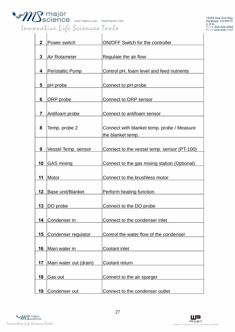
2 Power switch ON/OFF Switch for the controller
3 Air Rotameter Regulate the air flow
4 Peristaltic Pump Control pH, foam level and feed nutrients
5 pH probe Connect to pH probe
6 ORP probe Connect to ORP sensor
7 Antifoam probe Connect to antifoam sensor
8 Temp. probe 2 Connect with blanket temp. probe / Measure the blanket temp.
9 Vessel Temp. sensor Connect to the vessel temp. sensor (PT-100)
10 GAS mixing Connect to the gas mixing station (Optional)
11 Motor Connect to the brushless motor
12 Base unit/Blanket Perform heating function
13 DO probe Connect to the DO probe
14 Condenser in Connect to the condenser inlet
15 Condenser regulator Control the water flow of the condenser
16 Main water in Coolant inlet
17 Main water out (drain) Coolant return
18 Gas out Connect to the air sparger
19 Condenser out Connect to the condenser outlet
27

20 Water out Connect to cooling coil (Jacket) outlet
21 Water in Cooling to cooling coil (Jacket) inlet
22 O2 in Connect to the oxygen source (Optional)
23 Air in Connect to the air source (External air pump or house air)
24 USB port For data export
25 Power socket Power supply
26 Ethernet port Connect to the Ethernet and perform remote control function
27 RS-485 For system expansion
28 Pump 5 For external 5th pump
29 AUX 1 For system expansion
30 AUX 2
31 O2 flowmeter (Optional) Control the oxygen flow (Only available with O2
enrichment purchase)
28
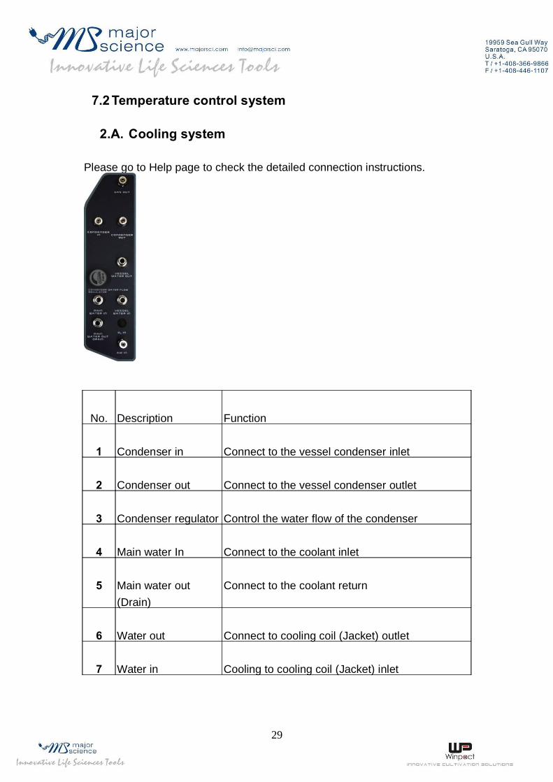
7.2 Temperature control system
2.A. Cooling system
Please go to Help page to check the detailed connection instructions.
No. Description Function
1 Condenser in Connect to the vessel condenser inlet
2 Condenser out Connect to the vessel condenser outlet
3 Condenser regulator Control the water flow of the condenser
4 Main water In Connect to the coolant inlet
5 Main water out (Drain)
Connect to the coolant return
6 Water out Connect to cooling coil (Jacket) outlet
7 Water in Cooling to cooling coil (Jacket) inlet
29
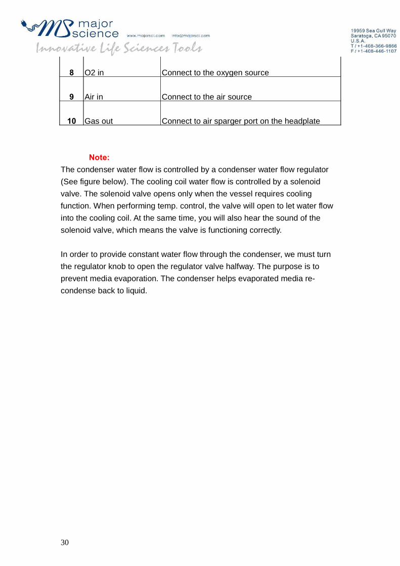
8 O2 in Connect to the oxygen source
9 Air in Connect to the air source
10 Gas out Connect to air sparger port on the headplate
Note:The condenser water flow is controlled by a condenser water flow regulator (See figure below). The cooling coil water flow is controlled by a solenoid valve. The solenoid valve opens only when the vessel requires cooling function. When performing temp. control, the valve will open to let water flow into the cooling coil. At the same time, you will also hear the sound of the solenoid valve, which means the valve is functioning correctly.
In order to provide constant water flow through the condenser, we must turn the regulator knob to open the regulator valve halfway. The purpose is to prevent media evaporation. The condenser helps evaporated media re-condense back to liquid.
30

2.B. Heating systems
No. Name Description
1 Coolant valve Control the coolant inlet flow
2 Heat exchanger Built-in heater to provide heating function
3 Circulation pump Help water circulate in the vessel
31

2.B.A.1. The minimum operating temperature in the culture ℃vessel will be 5 above the coolant. To provide an
efficient cooling control, the chiller temp. is normally set at ℃least 10 below the culturing temperature.
2.B.A.2. The water must be clean and free of particles.
2.B.A.3. The hardness of water should be below 12 German Degree of Hardness in order to prevent calcareous deposits.
Defects and damage caused by dirty water or calcareous deposits will not be covered by our warranty!
32

7.3 Culture vessel
3.A. Headplate Arrangement
No.
Name Function
12345
Feeding portInoculation portTo air spargerSeptum portAntiFoam probe
For Acid/Base/Antifoam/Substrate additionTo introduce the inoculumIntroduce air into the culture mediaSmall volume sample injectionDetect the foam level
33

6789
10111213
Spare port for DO/pH probeThermowellCooling coil inCooling coil outCondenserSampling portT-hand lifterScrew nut
For installing the DO/pH probeFor Pt-100 temp. probe insertionConnect to “Water in” port on the controllerConnect to the “Water out” port on the controllerPrevent culture media evaporationSampling/harvesting the culture mediaFor vessel transferFor headplate fixation
3.B. Vessel body
34

No.
Name Function
123456
78
Glass bodyHeadplateSupporting rodsImpeller(Pitched-blade type)SpargerBaffle
Condenser in portCondenser out port
Made from borosilicate glassArrange each port on the top plateSupport/Protection for the vessel bodyPerform mixing and agitationSparge gas into the culture vesselDisturb vortex and increase aeration efficiencyCondenser coolant inletCondenser coolant outlet
Section 8 Control interface
The control interface can be structured into 8 display screens depending on the functions:
35

1.A.A.1. Monitor: Shows the status and readings from the sensor
1.A.A.2. Pump: Controls the peristaltic pump speed and movement
1.A.A.3. Control: Performs manual or automatic control of each parameter
1.A.A.4. Setting: Sets up a schedule for the automatic process
1.A.A.5. Chart: Plots and records the trend of a fermentation process
1.A.A.6. Calibration: Performs sensor calibration
1.A.A.7. Maint.: For service and maintenance only
1.A.A.8. Help: Instruction for cooling system and tubing connections
1.1 Monitor
Once you start the system, monitor page will be shown as the first screen. Detailed descriptions are classified into nine areas (Area A - I).
36

Area A: Indicates the system condition. If this area shows a green light and “ON-LINE”, the system is working under normal condition. If it shows a red light and “OFF-LINE”, there may be a problem, and you should consult with a Winpact service operatorArea B: This area allows you to switch between each pageArea C: Displays the readings from sensors such as DO (Dissolved oxygen), pH, Temp. and optional devices such as ORP or CO2/O2 Analyzer. Also shows the set value for your control process (SV: set value; PV: present value). If the optional device is selected, the readings will also be displayed (Ex. CO2/O2, O2 Flow)
Area D: System login button. Provides access for different usersArea E: Displays the condition of each device. If the device is currently operating, the color will change to flashing red
Circulation pump Solenoid valve Heat exchanger
37

Area F: When the system is logged in via remote control, this area will display the remote IP addressArea G: Timer for process time calculationArea H: Displays the system operation mode. In this case, the screen display is “MANUAL” to indicate the system is operating under manual mode. Area I: This area shows the status of the fermentation process. When entering the automatic mode from the manual mode, the message will switch from the ellipsis “…” to the running table message to indicate the automatic process.Note 1: If your system is equipped with the O2 enrichment device (optional), your monitor screen will show an additional O2 solenoid valve icon (Boxed area). You can use this to manually control oxygen flow. Note 2: Your vessel display will change according to your System Setup selection on Maintenance page (please see section 8.7)
38

1.B. How to control the oxygen gas flow(Optional device)
1.B.A.1. Connect your oxygen source to the O2 in port on the controller. Please go to Section 6.3 for more details.
1.B.A.2. Open the controller back panel and you will find two pressure gauges (see figure below). The upper one is for oxygen, lower one is for air. Open the oxygen source and manually adjust the pressure gauge to the desired value. The pressure limit for the culture vessel 1 bar (14.5 psi). If you are using a cylinder as the O2 source, please be sure to use an external regulator to reduce your inlet gas pressure (see Section 6.3).
1.B.A.3. On the front panel, press the button to manually open the oxygen valve. Adjust the flow rate using the oxygen rotameter.
39

1.C. How to login to the system
1.C.A.1. Please login before you start system operation
1.C.A.2. Press and the login dialog will pop out
1.C.A.3. Select “Supervisor” and key in “1234” (Default password) as the password
1.C.A.4. Press “OK” then system will enter the monitor page
1.C.A.5. To log out of the system, press
Note: Users can access the system using different user names and user levels. Factory mode is for manufacturer and system maintenance purposes. The user can only choose “Supervisor” and “User” as the user ID. The difference between these two user ID’s will be explained in detail in Section 8.4. To change the password, also see Section 8.4.
40

8.2 Pump
2.A.A.1. How to change the pump speed:
Assign pump speed from the rpm column
Peristaltic pump speed range: 1 – 65 rpm. Increment: 1 rpm
2.A.A.2. How to change the pump direction
Use and to switch the pump direction forward or backward.
41

2.A.A.3. Switch between manual/automatic mode
Use to switch between Manual and Automatic control.
2.A.A.4. Pump 5 is for the optional external pump
Four silicon tubing sizes are available. Please check the table below for the nominal flow rate.
Nominal flow rate at 1 rpm (ml/min)
Tube inner diameter
0.8mm 1.6mm 3.2mm 4.8mm
Flow rate at 1 rpm 0.06 0.21 0.8 2.8mm
2.A.A.5. How to turn off the peristaltic pump
In automatic mode:
Go to setting page, press and enter the pump application page, choose
which pump you want to switch off and switch the pump application to . This assigns the specific pump to no application.
42

8.3 Control
You can either manually control each parameter or run automatic control of your fermentation process
Area A: Automatic mode
3.A.A.1. Start an automatic fermentation process
Press the button. The system will start running the process
according to the Set Temperature / Stirring table and pump-feeding schedule. To set up the table and schedule, go to the Section 8.4 setting page.
3.A.A.2. ACID Start function
If you use the function, the automatic mode will only be
43

triggered when the pH reaches the set value. To set the pH start point, go to the Section 8.4 setting page for Acid-Start setup.
Note: This function is specifically designed for lactobacillus culture. The cells produce acidic metabolite as they grow and the pH drops continuously. When the pH drops to the set points, the automatic mode will activate and the whole operation turns to automatic mode by running the rpm table, Temp. table, Feeding table and controls the pH within the set range (pH Auto-setup).
3.A.A.3. Stop an automatic fermentation process
Press to terminate an automatic fermentation process.
Area B: Manual control mode
1.A.A.1. Agitation control
-Change the agitation speed from the RPM column.
-Press to start manual agitation.
-To stop agitation, press again.
44

3.A.A.4. Temperature control
-Change the temp. from the temp. column
.
-Press to perform temp. control
-Press to disable temp. control
3.A.A.5. pH control parameter Setting
-Change the pH value from the pH column
-Press to start pH control
-Press to stop pH control
Note: Before using the pH control function, please assign pump applications for pumping Acid or Base. You can also define the dead-band (pH control range) and pulse interval for pumping the reagents. The detailed settings will be mentioned in Section 8.7 maintenance page.
45

3.A.A.6. DO Cascade
-Press to start DO cascade control.
-Before using the DO cascade function, go to the setting page to change the DO cascade parameters. The detailed setting will be mentioned in the next section.
8.4 Setting
In this page, you can program the automatic fermentation process and set up the DO cascade parameters
46

4.A. Automatic Agitation Program
Press to program the automatic agitation schedule.
Fill in the table according to the desired settings.
Note: You can set up 15 steps. In this case, the first step will run at 25 rpm for 60min., then 200rpm for next 60min, and so on.
Note: To fully stop agitation under programmable mode, you will need to set two step settings. For the first step, set RPM to 0, and MIN. to 1, then on the second step, set RPM to 0 and MIN. to 0 (The program stops at the previous step indefinitely, which in this case would be 0 RPM).
47

4.B. Automatic Temperature Program
Press to program temp. setting. The process of the temperature
program is basically the same as agitation program.
℃Note: There are 15 steps available. In this case, the temp. is kept at 50 for ℃the first 60 mins, 60 for the next 60 mins, and so on.
Note: You cannot stop temperature control fully under programmable mode.
48

4.C. Peristaltic Pump setting page
4.C.A.1. Press and enter the pump application page.
Assign an application for each peristaltic pump. You can assign the peristaltic pump to pump Acid, Base, Antifoam or Substrate. You can also assign one to four pumps for the substrate feeding:
Acid:
Base:
Antifoam:Substrate feeding:
Note: When using CO2 gas as acid control, acid pump will be disabled.
49

4.C.A.2. To set up a feeding schedule, use the table above to run the specific schedule you need. You can set up the pulse interval using the table.
Example:If you need to program Feeding for continuously feeding for 2 hours, you could set the feeding pump ON for 60 seconds, OFF for 0 seconds and 120 cycles in step 1; or set ON for 60 minutes, OFF for 0 minutes and 2 cycles in step 1.
In this page, pump 1 is assigned for pumping Feed 1, pump 2 for Antifoam, pump 3 for Base and pump 4 for Acid. The feeding pump is set at ON for 5 seconds, OFF for 2 seconds and 10 cycles in step 1. When finishing step 1, the feeding pump will start entering step 2. Up to 15 steps are available in this table.
You can set up the feeding schedule based on your tubing flow rate. With this table, you can calculate how much volume can be pumped into the vessels.You can change the time unit by switching the Second/Minute button
4.C.A.3. To cancel pump applications, switch the pump application to
4.D. DO cascade Setting
4.D.A.1. DO (Dissolved Oxygen) Cascade
Our DO cascade program is specifically designed to meet most of your experimental needs when running a fermentation/bio-reaction experiment. DO control usually does not come online until bacteria/yeast starts to grow exponentially, which consumes tremendous oxygen in a short period of time. So the purpose of the DO Cascade program is to maintain the DO level within the system once the DO set point value has dropped to a significant
50

level which may affect the result of the experiment. If DO level never reaches the set value, the DO cascade program will not initiate hence it will not be activated. For example, if your DO set point (SV) is set at 40% and the present value (PV) is 65%, DO cascade will not activate since PV has not dropped below 40%. No action will be taken by the DO Cascade program because it has not been triggered or activated.
4.D.A.2. DO Set point
DO set point acts as an activator for the DO cascade program (as explained in the previous section) and also acts as a control point for your DO level.
This is the set value you require for the DO level during your experiment.For example, DO level is set at 40.0%, which means when DO Cascade is triggered, it will maintain DO level at 40.0%.
This setting here allows you to add substrates through your pump feeding when DO level drops below the set value (e.g. 40.0%). You could select the feeding pump you assigned on (using the pump setting). Once the feeding program is triggered, it will run to completion.
4.D.A.3. Setting Menu
51

The DO Cascade setting menu is located under the Setting page. Its feature can be divided into two sections: Control Strategy and Feeding Strategy.
Control Strategy (1):
Settings in the black box, this strategy accommodates majority of the user needs. These settings allow you to adjust DO level using Agitation, O2 enrichment module, O2 with mass flow controller enrichment or Gas Mixing Station.
Feeding Strategy (2):
Settings in the red box, this is commonly used for any user who wants to harvest secondary metabolites during the experiment or needs to activate a feeding program at a specific DO condition. Hence with the First Trigger and Second Trigger options, whereas Second Trigger will not activate
52

unless First Trigger condition has been met and is true. Details of this strategy are explained on page 7.
4.D.A.4. Control Strategy
After setting your DO value, let’s continue to the right side of the screen, you should see there are 2 stages available for your DO control. When DO Cascade is in motion, the program will run stage 1 first, if stage 1 method fails to maintain the DO level, the system will proceed to stage 2.
Selecting the right method to use:
By pressing the rectangular button, you could select which specific method you prefer to run for each stage.
Different Methods and related input values:
b.1 StirrSelect this to use agitation to increase or decrease your DO level
53
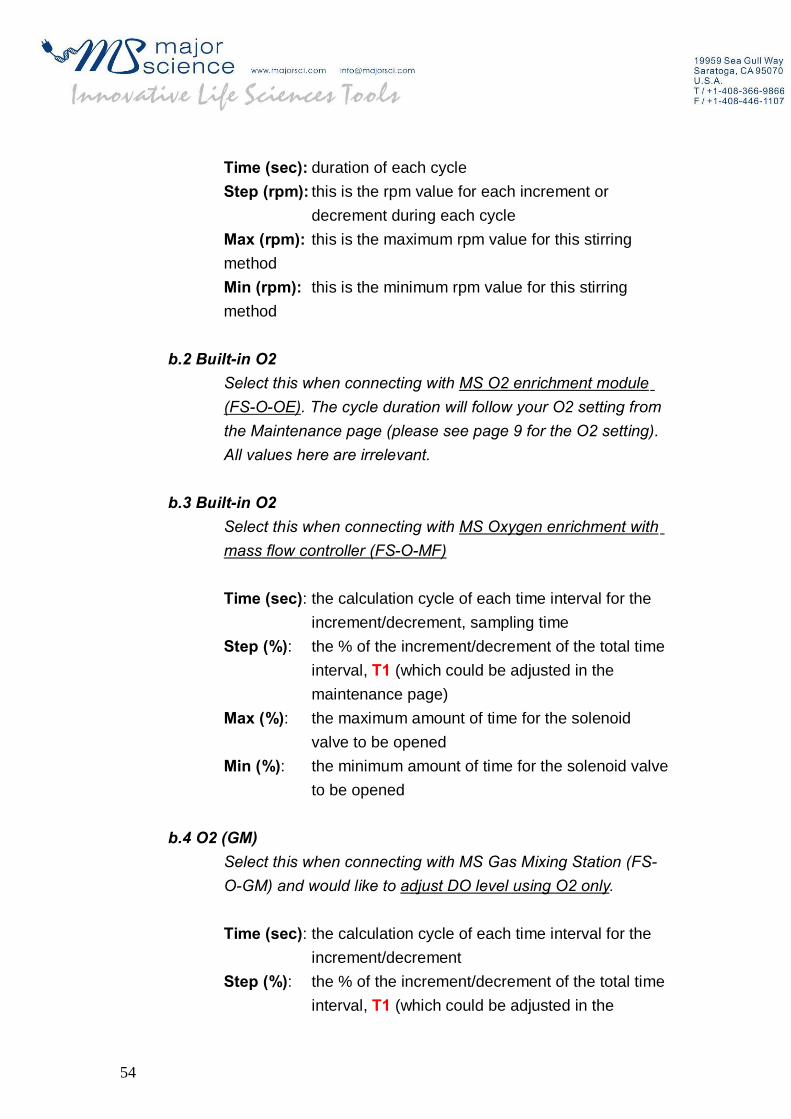
Time (sec): duration of each cycleStep (rpm): this is the rpm value for each increment or
decrement during each cycleMax (rpm): this is the maximum rpm value for this stirring methodMin (rpm): this is the minimum rpm value for this stirring method
b.2 Built-in O2Select this when connecting with MS O2 enrichment module (FS-O-OE). The cycle duration will follow your O2 setting from the Maintenance page (please see page 9 for the O2 setting). All values here are irrelevant.
b.3 Built-in O2Select this when connecting with MS Oxygen enrichment with mass flow controller (FS-O-MF)
Time (sec): the calculation cycle of each time interval for the increment/decrement, sampling time
Step (%): the % of the increment/decrement of the total time interval, T1 (which could be adjusted in the maintenance page)
Max (%): the maximum amount of time for the solenoid valve to be opened
Min (%): the minimum amount of time for the solenoid valve to be opened
b.4 O2 (GM)Select this when connecting with MS Gas Mixing Station (FS-O-GM) and would like to adjust DO level using O2 only.
Time (sec): the calculation cycle of each time interval for the increment/decrement
Step (%): the % of the increment/decrement of the total time interval, T1 (which could be adjusted in the
54

maintenance page)Max (%): the maximum amount of time for the solenoid
valve to be openedMin (%): the minimum amount of time for the solenoid valve
to be opened
b.5 O2/N2 (GM): (FS-O-GM)Select this when connecting with MS Gas Mixing Station (FS-O-GM) and would like to adjust DO level using O2 for increasing DO and N2 for decreasing DO.
Time (sec): the calculation cycle of each time interval for the increment/decrement
Step (%): the % of the increment/decrement of the total time interval, T1 (which could be adjusted in the maintenance page)
Max (%): the maximum amount of time for the solenoid valve to be opened
Min (%): the minimum amount of time for the solenoid valve to be opened
Operating procedure using Control Strategy
The control strategy allows you to maintain your DO using the two methods of your choice.
For the setting given above, stage 1 is using the Stirr method and stage 2 is using the Built-in O2 method. Once the DO level drops below 40%,
55

DO Cascade will activate the Stirr method by increasing the agitation speed by 20 rpm per cycle. If the current setting is 200, for every 5 seconds, it will increase 20 rpm to 220 rpm, and check the DO level again, if another increment is required, it will increase another 20 rpm to 240 by the next 5 seconds, and if the system reaches your set max RPM value (in this case, 500 rpm) and still unable to adjust the DO level to 40%, it will proceed to Stage 2.
For Stage 2, as the example given below, this setting is using the Built-in O2 enrichment module, as previous stated, if you have purchased Gas Mixing station, Oxygen enrichment with mass flow controller, or simply the oxygen enrichment module, you need to select it appropriately in order for the setting to work properly.
c.1 Flow chart of increasing DO
56

c.2 Flow chart of decreasing DO
4.D.A.5. Feeding Strategy
Once your DO level falls/reaches your set value (First Trigger value, in %), it will activate your second Trigger Value, once the DO raises up to the set value, the feeding schedule (by selecting the Feed you want) will initiate. The feeding strategy is designed for experienced user who understands his experience thoroughly and would like to schedule a feeding schedule based on the metabolic process of his bacteria such as lactobacillus. This feature allows you to add substrates feeding based on the changes of the DO level.
Operating procedure using Feeding Strategy (red box)
57

As the setting given above, when the DO level drops from 40% to 20%, it will active the first trigger, which is still in idle mode but waiting for the second trigger value to be active. Once the DO level rises from 20% to 50%, if a feeding schedule is selected, it will be activate.Note: if DO level rise directly from 40% to 50%, it will not activate the feeding strategy because the first trigger value (20%) was not reached.
4.D.A.6. Finding your T1 (total time interval)
Go to Maintenance page, on this page you should be able to locate the total time interval for the oxygen valve. (for FS-O-OE and FS-O-MF)
58

T1 = the cycle duration in time for the oxygen valve
T2 = the duration in time the valve will open during each cycle.
Note: when selecting your O2 source, these values (values in blue box from the picture below) will not apply to O2 enrichment module. Instead, Cascade will only use the pulse interval of the oxygen cycle (T1 and T2 in red box from the picture above) to adjust your DO level. All values are irrelevant.
59

Example: In the settings given below:
Once the first stage of the DO cascade has failed to maintain the dissolved oxygen level, the system will automatically enters the second stage and introduce pure oxygen to raise the DO value. Make sure to have the Oxygen selection set to ON in order to have this feature to work properly.
In this case, the Oxygen valve will open every 10 seconds, with increment of 1 second (10% of 10 seconds [T1] = 1 second) with maximum opening valve time as 10 seconds (100% of 10 seconds [T1] = 10 seconds) and minimum opening valve time as 1 second (10% of 10 seconds [T1] = 1 second).
So the system will start with opening valve for 1 second, and close for 9 seconds, if it failed to maintain the DO level, it will proceed with opening valve for 2 second (1 second initial with increment of 1 second), and close for 8 seconds, and so on.
For every 10 seconds (Time), the system will monitor the DO level to calculate the increment or decrement of the solenoid valve.
60

4.D.A.7. The Restore Delay
The minimum duration in time (only in digits, not decimal points) for which the system will evaluate before it de-activate the program. (This is to make sure DO level reaches the set point and is stabilized)
4.D.A.8. The Response dead-band value
As our system’s standard value, the response dead-band is 5 %. This value is the neutral buffer area where no action occurs. The purpose of the response dead-band value is to prevent oscillation or repeated activation-deactivation cycles of DO cascade, which may cause great fluctuation of the DO level and shorten the life of the solenoid valve. This means that if your DO set point is at 40%, the DO cascade program will not initiate and until the DO level reaches 35% (40 % - 5% [dead-band value]); vice-versa the program will sustain in the idle when the DO level reaches 45% (40% + 5% [dead-band value]).
Note: Response dead-band could be adjusted according to your need,
61

minimum setting is 1.5 %.
4.E. File Management
We use different parameters for different growth conditions. To save and manage these files, you can use the New/Open/Copy/Rename/Delete function.
4.E.A.1. Open a new file: Press the New button then the following dialog will show up. Choose a file name title (LAB1 ~ LAB5) and key in a number (0001 ~ 9999). Then press OK to establish a new file. You can save up to 59994 programs for different conditions.
62

4.E.A.2. Open a previously saved file: Press the Open button to open an existing file. Select the file you want to open and press OK.
4.E.A.3. Copy a file: You can copy an existing file using copy function. The copied file allows you to further fine-tune each parameter if the growth conditions are similar.
4.E.A.4. Rename a file: Rename an existing file using rename function.
4.E.A.5. Delete a file: Delete saved files from the system memory.
4.E.A.6. Display a file name:
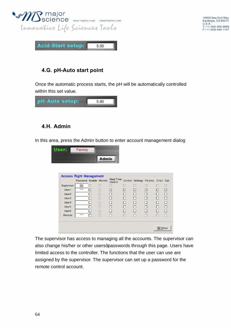
4.F. Acid-start setup
This function is primarily used for Lactobacillus fermentation. To use this function, the user must input a pH value for Acid-Start setup, and then push
the on the control page. Instead of immediately starting the
automatic process, the controller will wait for the pH in the media to drop to the desired level, and then begin fermentation.
63
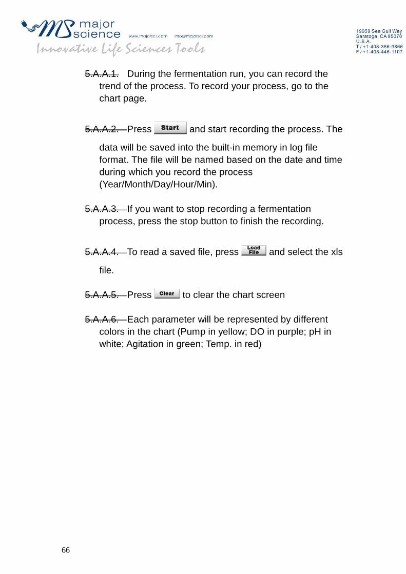
4.G. pH-Auto start point
Once the automatic process starts, the pH will be automatically controlled within this set value.
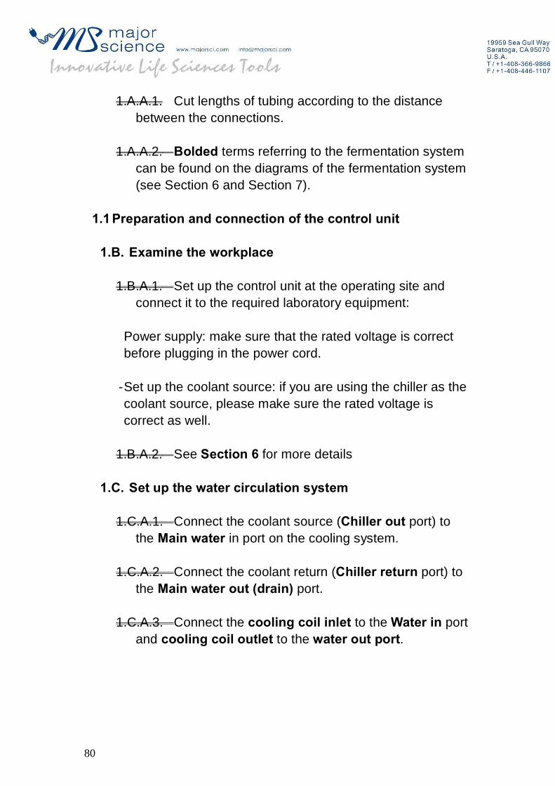
4.H. Admin
In this area, press the Admin button to enter account management dialog
The supervisor has access to managing all the accounts. The supervisor can also change his/her or other users’ passwords through this page. Users have limited access to the controller. The functions that the user can use are assigned by the supervisor. The supervisor can set up a password for the remote control account.
64

8.5 Chart
65
5.A.A.1. During the fermentation run, you can record the trend of the process. To record your process, go to the chart page.
5.A.A.2. Press and start recording the process. The
data will be saved into the built-in memory in log file format. The file will be named based on the date and time during which you record the process (Year/Month/Day/Hour/Min).
5.A.A.3. If you want to stop recording a fermentation process, press the stop button to finish the recording.
5.A.A.4. To read a saved file, press and select the xls
file.
5.A.A.5. Press to clear the chart screen
5.A.A.6. Each parameter will be represented by different colors in the chart (Pump in yellow; DO in purple; pH in white; Agitation in green; Temp. in red)
66

5.A.A.7. You can change the scale for each parameter in
the setting.
67

-Sample rate: Recording frequency. For example, if the sample rate is 10 seconds, the system will collect data points every 10 seconds.
-Temp.: Set the temp. display range
-Rpm: Set the agitation speed display range
-pH: Set the pH display range
-PO2: Set the dissolved oxygen display range
-ORP: Set the oxidation-reduction potential display range
-CO2: Set the carbon dioxide display range
-O2: Set the oxygen display range
In order to help the user monitor the trend of a fermentation, we have the “Long Curve” and “Short Curve” displays. The purpose is to zoom in and zoom out of the curve. The data points of a short curve are fewer than those of a long curve.(6) X Scroll Gap: Scrolls the increments 20 units forward or backward every
button.
(8) X Marker: 50 stands for the X-axis coordinate displays. It goes in increments of 50 such as 0, 50, 100, 150, and so on.Data can be exported to an external disk for further analysis using the USB ports.Press “Save to USB” to export the files.
8.6 Calibration
68

6.A. DO probe calibration
6.A.A.1. Press and enter the DO calibration page.
6.A.A.2. Disconnect the cable from the DO probe. Press for Zero calibration.
6.A.A.3. Place the probe into the vessel and connect the cable. Start the air pump and agitation to saturate the media dissolved oxygen.
6.A.A.4. Press to set the DO 100% point when the sensor is fully polarized.
6.A.A.5. Press to complete DO calibration.
69

6.B. pH probe calibration
pH calibration should be performed before sterilization.
70

6.B.A.1. Press and start pH calibration
6.B.A.2. Place the pH probe into the pH 7 standard solution. Wait until the pH value becomes stable, then press
for Zero calibration.
6.B.A.3. Clean the pH electrode with pure water, then dry it with Kimwipe tissue.
6.B.A.4. Place the pH probe into the pH 4 standard solution and wait until the pH value is stabilized, and then press
for Span calibration.
6.B.A.5. Press to complete pH calibration.
6.B.A.6. Clean the electrode again with pure water and dry it afterward. Disconnect the probe and install the probe into the vessel.
6.C. Touch screen calibration: Use this function to align the screen position
6.C.A.1. Press the “Touch Calibration” button. A green screen will appear.
6.C.A.2. A flashing cross will appear in the corner for the first calibration point. Press and hold it down until the circle fills blue.
6.C.A.3. Repeat with the remaining 3 points
6.D. System time: Change the Year/Month/Hour/Min settings and press “Set” to correct the system time
71

72

8.7 Maint.
This page is for mainly for manufacturer maintenance purposes and users have limited access.
73

7.A.A.1. Antifoam Detected Value: Foam level detection sensitivity can be increased/decreased by changing this value. This value has been optimized in the factory. There is no need to change the value. Default setting is 1800.
7.A.A.2. Antifoam pulse interval: Settings for antifoam addition duration. T1 stands for pump on interval and T2 stands for total duration.
7.A.A.3. Oxygen pulse interval: If your system comes with an oxygen enrichment device(Model no.: FS-O-OE), you can set up this parameter. T1 stands for oxygen valve pulse cycle, T2 stands for on time.
7.A.A.4. pH PID control: Set up the deadband (pH control range) for a pH control process. For example, if you want to control the pH between 7.2 and 6.8, set the deadband value at 0.2.
74

7.A.A.5. TCP/IP: Remote control internet settings (Please go to Section 10 for detailed settings)
7.A.A.6. System logs: help users trace system profiles. The system log records a power failure, calibration raw data or error messages. Also, the system log records the user login time and info.
-The calibration A/D value can be checked from calibration parameters dialog
75

7.A.A.7. System Setup: Option to designate your controller according to your vessel model and the accessories that come with it. Choose motor 1 (M1 105 Watt) for vessels under 7 Liters, and choose motor 2 (M2 180 Watt) for 10, 15 and 20 Liters. Choose DO probe type according to the probe you receive. Check the [CO2/O2 Gas Analyzer] box if you have the optional gas analyzer installed. System will automatically restart when the settings are applied.
Note: After selecting and changing “System Setup”, the system will reboot automatically once you hit the “Apply” button
Note: The PID value has been optimized before shipping. There is no need to change the PID settings.
76

7.A.A.8. Restore cali.: This function allows you restore the factory settings. If you accidentally mess up your calibration profile, you can press this button to restore the factory settings.
77

8.8 Help
The help screen guides the user set up the cooling and air system after the vessel sterilization
Section 9
78

Section 1 Operating the system
Note:
79
1.A.A.1. Cut lengths of tubing according to the distance between the connections.
1.A.A.2. Bolded terms referring to the fermentation system can be found on the diagrams of the fermentation system (see Section 6 and Section 7).
1.1 Preparation and connection of the control unit
1.B. Examine the workplace
1.B.A.1. Set up the control unit at the operating site and connect it to the required laboratory equipment:
Power supply: make sure that the rated voltage is correct before plugging in the power cord.
-Set up the coolant source: if you are using the chiller as the coolant source, please make sure the rated voltage is correct as well.
1.B.A.2. See Section 6 for more details
1.C. Set up the water circulation system
1.C.A.1. Connect the coolant source (Chiller out port) to the Main water in port on the cooling system.
1.C.A.2. Connect the coolant return (Chiller return port) to the Main water out (drain) port.
1.C.A.3. Connect the cooling coil inlet to the Water in port and cooling coil outlet to the water out port.
80

1.C.A.4. Connect the condenser in to the condenser inlet and condenser out to the condenser outlet. (Please refer to the 8.8 Help and the picture on 7.2 Cooling system)
81

9.2 Prepare the Culture Vessel and Accessories
2.A. Check the Equipment
While installing the culture vessel and fitting the probes and accessories, carefully check all parts for damage. Pay special attention to any potential cracks in the glass vessel, split in the O-rings (especially the one on the bottom of the head-plate), and any possible harm done to the seals on the rotating shaft.
Warning:
82
2.A.A.1. When a damaged glass vessel no longer has the bursting strength required for sterilization in the autoclave or running fermentation, it must be replaced immediately.
2.A.A.2. Damage to the seal can cause contamination of the culture during the fermentation process. Seals-on accessories which are often removed and refitted should be replaced regularly.
2.B. Vessel assembly and head-plate arrangements
2.B.A.1. Unscrew the screws on top of the head-plate and remove the head-plate.
2.B.A.2. Attach all parts (not including tubing) meant to be mounted onto the head-plate:
2.B.A.3. O-ring seal: make sure the O-ring is properly fitted onto the bottom of the headplate
2.B.A.4. Any port where there are no accessories part attached must be fitted with a blind port to prevent leakage.
2.B.A.5. If an O-ring is damaged, it must be replaced. You may grease the O-rings (especially the one between glass vessel and headplate) with silicon grease to prevent the O-ring from deforming over time and to stop air from escaping from the vessel.
2.C. Set up the air supply
2.C.A.1. Attach two pieces of silicon tubing to either side of a 0.2 micron air filter (provided). Make sure the tubing lengths are long enough to reach from the controller to the vessel. Use clamps to close the tubing on each side of the filter.
83

2.C.A.2. Secure one end onto the To air sparger port on the vessel and the other onto the “Gas out” port on the controller
2.C.A.3. With a storage bottle, connect one port with silicon tubing to the exhaust port on the top of the condenser.
2.C.A.4. Connect the other port to a filter (an exhaust filter) with a short piece of silicon tubing.
2.D. Set up the feeding port
2.D.A.1. Fill the 250 ml storage bottles with acid, base, antifoam reagent, or nutrient.
2.D.A.2. Connect them each with silicon tubing to the feeding ports on the head-plate. The tubing should be of sufficient length to allow for passage through the peristaltic pump in the control unit.
2.D.A.3. If no acid/base/antifoam/nutrient is used, then use a shorter piece of silicon tubing to connect the two feeding ports in order to prevent air leakage.
2.E. Media preparation
2.E.A.1. Attach a piece of silicon tubing to the sampling port and clamp the other end.
2.E.A.2. Adjust the height of the antifoam probe according the projected working volume. It is recommended that the user use at least 50 mm of tubing.
2.E.A.3. Prepare the media and reagents.
2.E.A.4. Pour the now mixed and ready-to-use media and water into the vessel.
84

2.F. pH calibration
2.F.A.1. Connect the pH probe to the pH probe port on the controller.
2.F.A.2. On the screen, select the Calibration tab and then select pH.
2.F.A.3. Stick the probe into a pH 7 standard solution and wait until stable.
2.F.A.4. Select Zero.
2.F.A.5. Clean and dry the probe.
2.F.A.6. Place the probe in pH 4 standard solution and wait until stable.
2.F.A.7. Select Span Set.
2.F.A.8. Press Finish then clean and dry the electrode again. (For more details in Section 8.6 calibration)
2.G. DO calibration
2.G.A.1. Select DO under the calibration tab.
2.G.A.2. Make sure the DO probe and the DO probe port on the controller are not connected and then select Zero.
2.G.A.3. Place the probe into the vessel and connect the cable.
2.G.A.4. Start the air pump and agitation.
2.G.A.5. Press Span Set when the sensor is fully polarized.
85

2.G.A.6. Press Finish. (For more details on 8.6 calibration)
2.H. Final details
2.H.A.1. Check all ports for proper connections.
2.H.A.2. Secure the head-plate back onto the vessel by tightening the four or six screws.
2.H.A.3. Make sure the o-ring on the bottom of the head-plate is fitted well.
2.H.A.4. Perform air leakage tests. If leakage happens, check again the possible leakage site.
2.H.A.5. Wrap any exposed electrode part of the sensor (DO and pH) with aluminum foil to protect against the impact of steam.
2.I.Sterilization of the culture vessel
2.I.A.1. Take care that all open ports on the head-plate of the culture vessel are closed.
2.I.A.2. Double-check that the electrode plugs are covered with aluminum foil.
2.I.A.3. Completely disconnect the water circulation system.
2.I.A.4. LOOSEN THE EXHAUST BOTTLE CAPS BEFORE STERILIZATION (Half-turn).
2.I.A.5. Put the culture vessel with all storage and 500 ml exhaust bottle into the autoclave.
86
2.I.A.6. For single wall vessels, proper sterilization requires a temperature of 121°C for 40 minutes. For jacket vessels, the time required for sterilization is 60 minutes.
9.3 Prepare the Fermentation Run
3.A. Post-sterilization
3.A.A.1. After sterilization, wear heat protective gloves and fasten the caps for all bottles immediately.
3.A.A.2. After culture vessel and all bottles cool down, bring them from the autoclave to your work-place. Take caution during transportation when moving things from the autoclave to prevent the loosening of any tubing or connected assemblies.
3.A.A.3. Place a piece of silicon tubing over the Air out port on the controller and insert the other end through a filter and then connect to the To air sparger port on the vessel.
3.A.A.4. Connect the water in port on the controller to the cooling water in (coolant inlet) port on the vessel.
3.A.A.5. Connect the water out port on the controller to the cooling water out (coolant outlet) port on the vessel.
3.A.A.6. Connect the condenser in port on the controller to the condenser in port on the condenser.
3.A.A.7. Connect the condenser out port on the controller to the condenser in port on the condenser (For more details on 8.6 DO calibration).
3.A.A.8. Remove the protective aluminum foil from the electrode connectors.
87

3.A.A.9. Connect the cable to the electrodes, including the pH probe, the pO2 probe and the foam level probe.
3.A.A.10. Fill up the thermowell with water. Insert the Pt-100 temperature probe.
3.A.A.11. Connect the tubing from the feeding bottle to the feeding port.
3.A.A.12. Place the silicon tubing through the peristaltic pump.
3.B. Priming
Perform “priming” to remove any air from the tubing:
3.B.A.1. Select the Pump tab on the controller.
3.B.A.2. Set the arrow to forward direction.
3.B.A.3. Enter the desired rate at revolutions per minute.
3.B.A.4. Press manual pumping button to perform priming
(For more details on the manually adjusting the peristaltic pump options, please see section 8.2 Pump)
88
3.C. Mount the motor
3.C.A.1. Fit the bumper onto the stirring shaft.
3.C.A.2. Locate the small notch on the motor and on the stirring shaft and place the motor onto the stirring shaft.
3.C.A.3. Secure the motor by matching the latch.
3.D. Cool down
3.D.A.1. Make sure the condenser regulator is open halfway.
3.D.A.2. Start the temperature PID control to the cool down the system (When you press the Temp. control button from the control interface, you will hear the sound of the solenoid valve. After cooling down the vessel to the working temp., wrap the heating blanket onto the culture vessel.
DO NOT WRAP THE BLANKET AROUND THE VESSEL BEFORE IT HAS COOLED FROM STERILIZATION! This could result in the blanket damage (Blanket limitation: 60°C). Damage caused by mishandling will not be covered by our warranty.
89

3.E. Inoculation
3.E.A.1. Use silicon tubing to connect the inoculation bottle to the peristaltic pump (similar to the feeding bottle).
3.E.A.2. Sterilize the feeding port and the silicon tubing. The user may apply a high temperature flame (≥1,200°C) toward the feeding port and silicon tubing opening for 10 seconds.
3.E.A.3. After proper sterilization of the feeding port, connect the silicon tubing to the feeding port.
3.E.A.4. Manually pump the seed cells into the culture vessel. You can change the pump speed in the setup menu to achieve a higher flow rate.
Note:
3.E.A.5. Tubing setup for the water-circulating system: Please go to the Help page to view the detailed connections.
3.E.A.6. Half-turn the condenser water regulator to provide a continuous flow to the condenser
3.E.A.7. Peristaltic pump
-Quick and simple tube change.
-Tubing is available in four sizes and five materials as follows:
Bore x wall
Autoprene Silicone Tygon Viton Prothane II
90

0.8mm x
1.6mm
T0016 SAT 24 T0016 SLT 25
1.6mm x
1.6mm
T0016 SAT 07 T0016 SLT 12 T0016 TYG
12
T0016 VIT
16
T0016 PRO
16
3.2mm x
1.6mm
T0016 SAT 08 T0016 SLT 16 T0016 TYG
13
T0016 VIT
10
T0016 PRO
10
4.8mm x
1.6mm
T0016 SAT 01 T0016 SLT 02 T0016 TYG
10
T0016 VIT
02
T0016 PRO
03
We provide #16 silicone tubing (3.2mm x 1.6mm) as the standard accessory. The silicone tubing is only for general purpose. Please do not use it for strong acid or base. To pump strong acid or base, please choose chemical resistant material (Viton or Tygon). Damage caused by misuse of liquids will not be covered by our warranty.
91
Section 10 Remote control setting
Remote control is achievable using web browser, which is platform free. Additional installation of software is not required.
10.1 Connecting your PC to the Winpact controller
There are two ways to connect your PC to Winpact controller: direct connection from PC to controller, or connecting through a network
1.A. Direct Connection (Controller to PC)
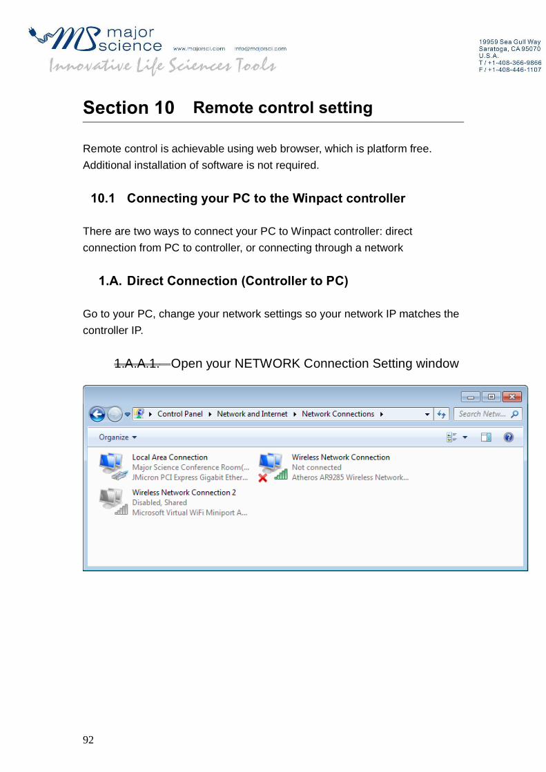
Go to your PC, change your network settings so your network IP matches the controller IP.
1.A.A.1. Open your NETWORK Connection Setting window
92
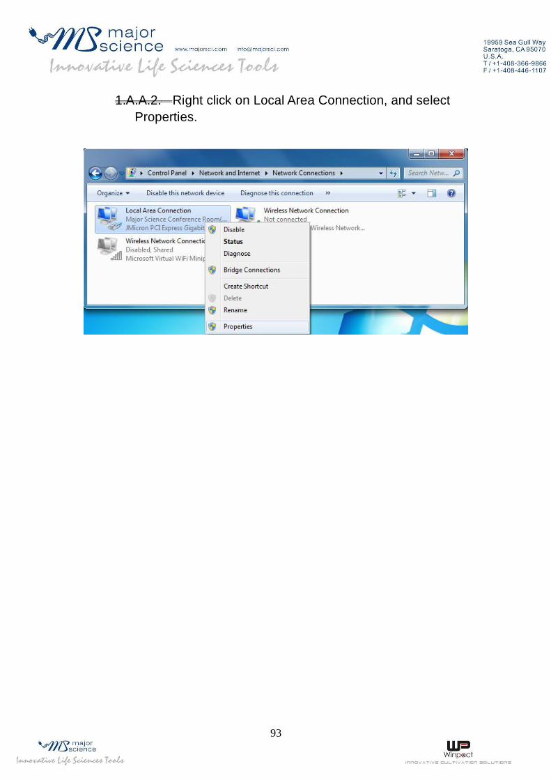
1.A.A.2. Right click on Local Area Connection, and select Properties.
93

1.A.A.3. Choose TCP/IPv4 (this would differ depending on your operating system), and select Properties.
94

1.A.A.4. Change the IP to an IP that’s in the same IP range shown on the controller. For example: default IP on the controller should be 10.0.0.166, change the IP on your PC to 10.0.0.55.
1.B. Indirect Connection (Controller to Network)
To connect through internet (LAN), you will have to setup the IP on the controller.Obtain a set of IP address that is within your network.Make sure that the IP you set for the controller is a FIXED IP, and that it does not conflict with any other IP that is within your network.
95

Make sure to reboot the controller after changing the internet settings.No additional software is required, just make sure that JRE (Java Runtime Environment) is installed on your operating system.
10.2 Controlling the Winpact system on your PC
2.A.A.1. Open your web browser and key in the IP address with Port number. (Default IP is 10.0.0.166, Port: 8080)
2.A.A.2. Click on “Remote Control” and the system will enter the login dialog. Type in the user name and password.
User: admin Password: 0000 (Default password)
96

2.A.A.3. Please skip the security dialog so that the login process can continue.
97

2.B. Program page
Monitor: The current value can be monitored from this page. The schematic diagram shows the working condition of each device. If the device is on, the color will be changed to red.
98

2.C. Chart: Real-time recoding or history data reading can be done in this page. The log file can be saved into the computer disk.
99

2.D. Manual settings: In this page, you are able to perform remote control of agitation speed, temperature and pH. Press SET button to set up the parameters.
100

2.E. Auto settings: In this page, you can set up the schedule for the automatic fermentation process.
Stirring table
Temperature table
101

Feeding table
For security reasons, our remote control function will be disabled if a firewall exists. The remote control works fine within an intranet. If you have any problems with the internet setting, please consult your IT department.
102

2.F. Exporting trend files into the USB hard drive for further analysis
2.F.A.1. In the chart page, press “Load File” and select the file you wish to analyze.
2.F.A.2. Plug the USB hard drive into USB port. Wait until the USB signal is detected, then press “save to USB” button to export the data.
2.F.A.3. On your operating system, open the file to be analyzed.
2.F.A.4. To plot the trend of a fermentation process, select the data you wish to plot. In this example, we select Time and Temp. for analysis.
2.F.A.5. Use scatter plot function to plot the fermentation process (X – axis: time, Y –axis: Temp.).
2.G. Understanding your data table
103
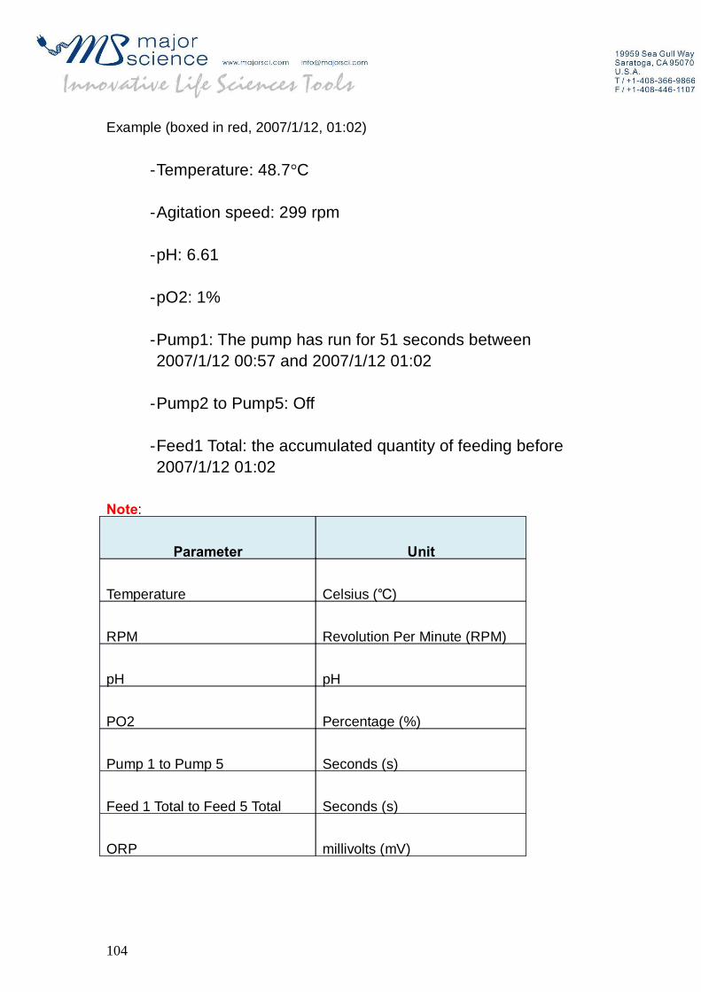
Example (boxed in red, 2007/1/12, 01:02)
-Temperature: 48.7°C
-Agitation speed: 299 rpm
-pH: 6.61
-pO2: 1%
-Pump1: The pump has run for 51 seconds between 2007/1/12 00:57 and 2007/1/12 01:02
-Pump2 to Pump5: Off
-Feed1 Total: the accumulated quantity of feeding before 2007/1/12 01:02
Note:
Parameter Unit
Temperature ℃Celsius ( )
RPM Revolution Per Minute (RPM)
pH pH
PO2 Percentage (%)
Pump 1 to Pump 5 Seconds (s)
Feed 1 Total to Feed 5 Total Seconds (s)
ORP millivolts (mV)
104

CO2 Parts per million (PPM)
O2 Percentage (%)
105

Section 11 Cleaning and Maintenance
11.1 Vessel Cleaning
1.A.A.1. Fill the vessel with a mild detergent and water solution
1.A.A.2. Let the solution stand for 1 hour, and then scrub thoroughly with a soft brush. A toothbrush may be used for smaller parts and hard to reach areas
1.A.A.3. Drain, and rinse several times with tap water
1.A.A.4. Rinse a final time with distilled water, and allow to dry
11.2 Control Station Cleaning
The control station can simply be cleaned by wiping with a damp cloth or towel
11.3 DO electrode information and maintenance
Please follow the instructions below to maintain your D.O. Probe:
3.A. Cleaning the probe
One effective way to remove contamination from the cathode surface is to wash it with a toothbrush and toothpaste. Then rinse with D.I. Water.
3.B. D.O. sensor malfunction
10 probable causes of D.O. sensor malfunction are listed below:
106

3.B.A.1. Punctured membrane
3.B.A.2. Torn or ripple membrane
3.B.A.3. Dirty cathode
3.B.A.4. Dirty or fouled anode surface
3.B.A.5. Damaged O-ring
3.B.A.6. Missing O-ring
3.B.A.7. Damaged cathode
3.B.A.8. Dirty membrane
3.B.A.9. Corroded connector
3.B.A.10. Electrolyte level too low
Reference: Summer 1998 Broadley-James corporation
3.C. Testing the D.O. Sensor membrane
One simple way to test the membrane puncture is to connect the membrane cartridge with a syringe using an adapter. Monitor the bubble formation during pumping (See figure). Bubble formation may indicate leakage of the membrane.
107

3.D. Membrane replacement and electrolyte refill
3.D.A.1. Keep the sensor in an upright orientation, then unscrew the old membrane cap.
3.D.A.2. Remove the membrane, expose the glass body in the air.
3.D.A.3. Clean the tip of the glass body with a soft tissue.
3.D.A.4. Gently introduce 1.5 ml DO solution into the new membrane cap.
3.D.A.5. Carefully screw the new membrane cap onto the sensor shaft.
How to replace the DO solution
108

3.E. Membrane kit
3.E.A.1. DO solution, 20ml
3.E.A.2. Spare O-rings
3.E.A.3. Pipette
3.E.A.4. Polishing strip
3.E.A.5. Membrane cartridge
3.F. Storage and electrolyte replacement
The DO probe can be stored in 3M Potassium Chloride solution. The DO solution is used for inner cartridge electrolyte replacement. After using the probe a few times, you can check the solution condition by nude eye (check if there is precipitation or color change). If precipitation or color change occurs, please replace with new solution.
11.4 pH probe information and maintenance
Please follow the instructions below for your pH electrodes maintenance:
109

4.A. Cleaning the measuring electrode
4.A.A.1. Remove any deposits from the membrane or diaphragm by rinsing the electrode with mild detergents.
4.A.A.2. For calcium deposit, soak the electrode in a 0.1M HCl solution for a few minutes.
4.A.A.3. For proteins, soak the electrode in a solution of 1% pepsin and 0.1M HCl for several hours.
4.A.A.4. Inorganic coatings can be removed using commercially available glass cleaning solution (e.g., Windex).
4.A.A.5. Silver sulphide deposits, caused by the reaction of sulphides containing solution with silver chlorides in most electrodes, can be removed by soaking the electrode in a 0.1 M thiourea/HCl solution until the diaphragm is totally bleached.
4.A.A.6. To remove highly resistant deposits, hydrogen peroxide or sodium hypochlorite is recommended.
4.A.A.7. Rinsing the electrodes in a 0.1M HCl or 0.1M NaOH solution for a few minutes may be able to remove the acid or alkaline soluble deposits.
4.B. After cleaning
After the cleaning process, soak the TrupH electrode in the storage solution (3M KCl) for 12 to 24 hours. Cleaning solution may penetrate the diaphragm during cleaning. It is necessary to calibrate the pH measurement after the hydration process.
110

4.C. Storage of the electrode
For long-term storage, immerse the pH electrode in a 3M KCl solution.
4.D. Aging
Aging is unavoidable. However, proper maintenance can delay the process. Typical symptoms of an “aged” measuring electrode includes:
4.D.A.1. Increased response time
4.D.A.2. Increased membrane resistance
4.D.A.3. Declining slope, especially in the alkaline region
4.D.A.4. Shift of the asymmetry potential (zero point shift)
Lifetime of each electrode depends on the operating and handling conditions. The electrodes have a maximum operating lifespan of 18 months if handled properly. The lifetime may only last 2 months if operated at the temperatures exceeding 90°C. The electrode stops working after only 2 weeks when exposed to strong base (pH > 13) and high temperature (> 90°C). In most cases, we will find that pH electrodes age gradually. An increased response time is the most direct indication of aging. If the response time becomes unacceptable for your fermentation process control, we recommend replacing the pH electrode with a new one.
4.E. Storage solution
To prevent dehydration of the probe, we recommend storing the probe in the 3M Potassium Chloride solution every time after use.
111