Embed Size (px)
Citation preview
Detail Design of Wings
• Wing Structure– Internal Structure
• Ribs
• Spars
• Stringers
– External Structure• Skin : carry shear stress, transfer the aerodynamic
loads to the internal structures
Wing
Aerodynamic Forces: - Lift Distribution - Drag - Bending Moment - Pitching Moment (Torsional Moment)

Wing Structures
Wing structure should have asufficient strength, stiffness,and light weight structure witha minimum of manufacturingproblems.

Spars
• Wing spars are long members which run from theroot to the tip of the wing.
• Typically a wing has two spars, a front spar and aback spar.– Multi-spar designs are used on larger wings and
on military aircraft• Reliability(fail-safe design) and tolerance to battle
damage
• Spars primarily carry the aerodynamic loadsdeveloped by the wing.

Spar Design
• Because of the bending loads on wings, sparsare designed for stiffness in bending.– Spar “cap (flange)” : carry normal stress due to
bending, same idea as an I-beam design– Spar “web” : carry shear stress
• Since the first failure mode is often buckling ofthe web, web stiffeners are often added.
• A “crack stopping joint” is often added forsafety.

Spar designs - Illustrated
Max. normal stress due toshear & bending @ top/bottomof the spar => Cap (Flange)
Max. shear stress due to shear& bending @ middle of spar=> Web

Spar designs - Illustrated
Spar Cap Type :* Simplicity of construction, mostly
used on general aviation aircraft* Skin will buckle at at very low load
In high speed A/C, wing structure isusually made of multiple spars
Torsional moment is primarilyresisted by the skin, front/rearspars => form portion of the“wing torque box”
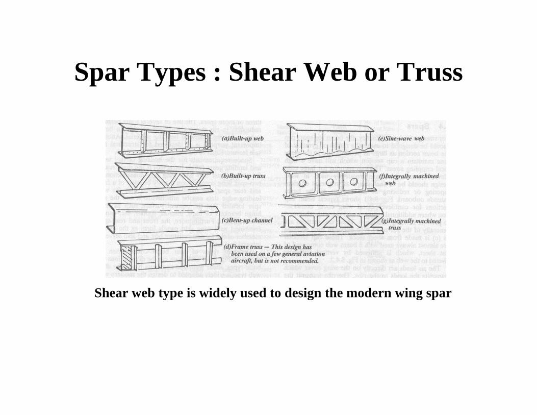
Spar Types : Shear Web or Truss
Shear web type is widely used to design the modern wing spar
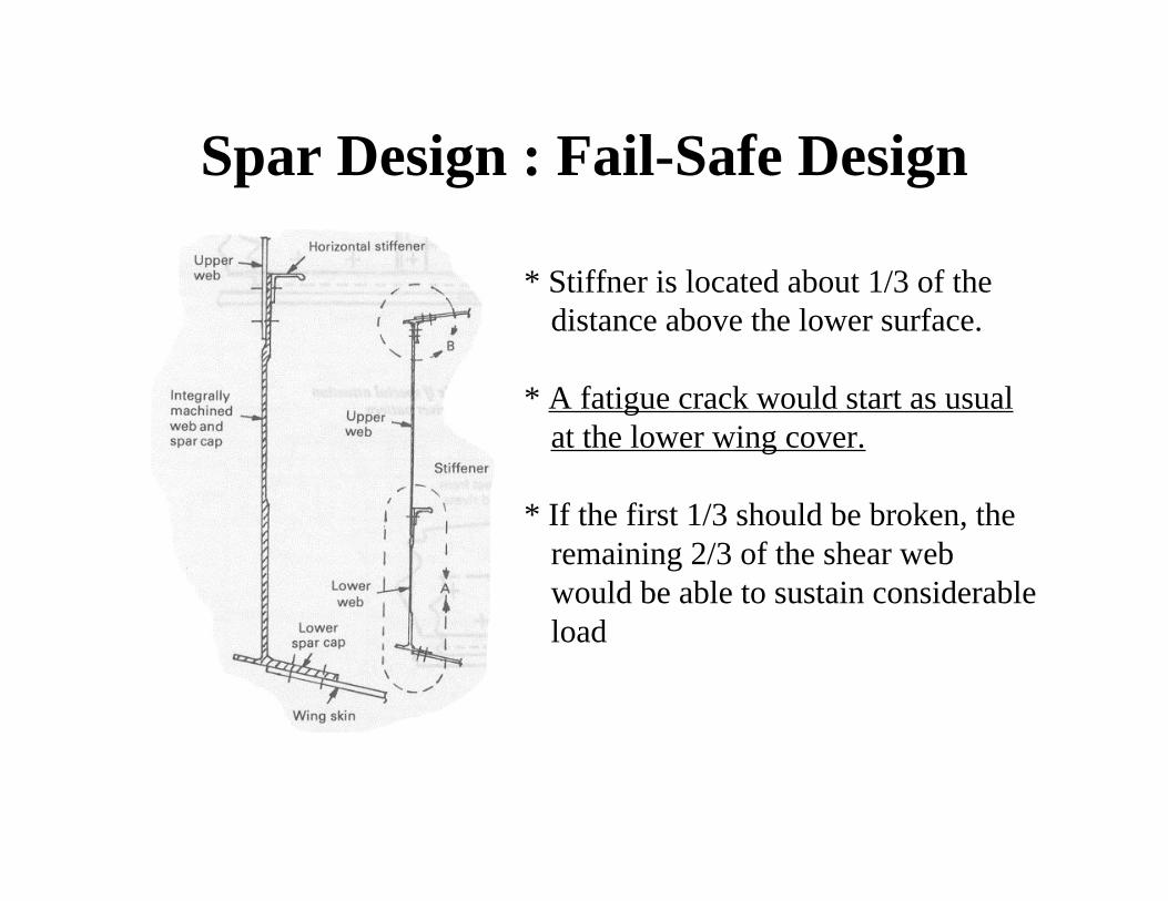
Spar Design : Fail-Safe Design
* Stiffner is located about 1/3 of thedistance above the lower surface.
* A fatigue crack would start as usualat the lower wing cover.
* If the first 1/3 should be broken, theremaining 2/3 of the shear webwould be able to sustain considerableload

Ribs
• Ribs are used to define and produce the airfoilshape
• Support skin, prevent wing skin buckling
• They transfer primary loads from the controlsurfaces and undercarriage, such as externalstores, to the spars and the skin.

Stringers• Z,J,Top Hat shape stringers
• Attached to the wing skin : stiffen the wing skin,prevent buckling– Riveting, or Bonding

Stringers• Machined skin combining with machined stringers
(integral stiffened panel) are the most efficientstructures
• Light weight, high strength construction
• Advantages : skins can be tapered spanwise,thickened around holes and to produce rib lands

Wing Skin
• Gives the wing it’s shape
• Carries loads– Bending and shear loads
– Torsional loads caused by control surfaces andother features attached to the wing
– Portion of the wing “torque box”
• Creates walls for the wing mounted fueltanks

The wing “Torque Box”
• Front and rear spars together with the skinforms a “torque box”, stiffened by the ribs,which resists wing bending

The wing “Torque Box”
• The volume between the ribs can be fittedwith fuel tanks
• Details of torsion box design and analysis -AET 417
Pylons (hardpoints)
• Aircraft wings often carry accessory equipment, weapons,engines, and sometimes landing gear is attached near toroot of the wing. The attachment points are called pylons.– Text refers to landing gear assembly as “undercarriage”
– Additional internal wing structure needed around the pylons.
– “Wet” pylon - contains provisions for externally mounted fueltank.
– Weapons pylons - electronic connections for weapons systems arenecessary.
– . . . .
Flaps and Slats
• Lift enhancement devices for low speeds– Inefficient at cruise speeds, but needed at takeoff
and landing• Flaps are airfoil extensions mounted at the rear of the
airfoil section.• Slats(Leading Edge Flap) are similar extensions
mounted to the front of the wing.• Increase in lift by changing airfoil camber

Flaps and Slats
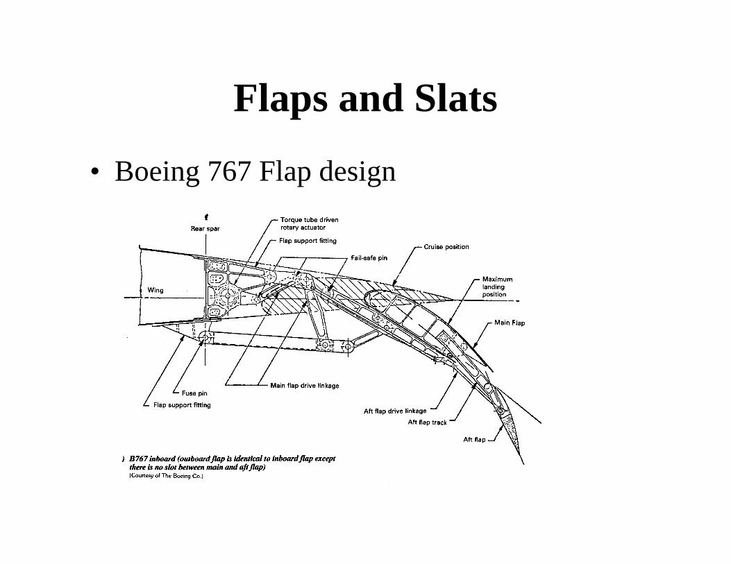
Flaps and Slats
• Boeing 767 Flap design

Flaps and Slats• Boeing 747 Slat Design - Kruger type flap
• Gap between slat and LE of airfoil : - To avoid leading separation by allowing air to flow through
Spoilers• Usually located directly in front of the flaps, and have a
similar span.
• Text differentiates between spoilers, which may bedeployed in flight, and “lift dumpers”, which are onlydeployed on the ground. This distinction is often notmade.– Inboard spoilers are the “lift dumpers”, also called “ground
spoilers,” and can’t be deployed in flight because of possiblebuffeting on the tail section
– Outboard spoilers, when deployed in flight, are sometimes called“speed brakes”.

Spoilers
• Functions of spoilers:– Reduce lift at landing
– Reduce aircraft speed
– Aid in slowing the aircraft after landing by:• Increasing the normal force on the wheels
• Preventing aircraft bouncing back into the air
• Providing additional drag

Ailerons
• Attached to the outer portion of the wing toprovide roll control– On larger aircraft, both inboard and outboard
ailerons are in place• Low speed - outboard ailerons used
• High speed - inboard ailerons used
– On some military aircraft, roll control isprovided on the tail unit, called a “taileron”

Deployment of ailerons

Deployment of ailerons
Frise Aileron is designed toeliminate adverse yaw
+∆∆LMore Drag
-∆∆LLess Drag
Yaw

Aileron EffectivenessControl Reversal
Aileron EffectivenessControl Reversal
• On larger aircraft, both inboard and outboardailerons are in place
• Low speed - outboard ailerons used
• High speed - inboard ailerons used
Summary of wing design• Competing yet coupled factors in wing design
– Structural considerations• Weight• Strength• Stiffness
– Aerodynamic considerations• Cruise• Takeoff and Landing• Maneuverability requirements
– System configuration (fuel storage, weapons, etc.)• Semi-monocoque design meets these requirements
very well