Embed Size (px)
Citation preview

Section One …………………………..Installation Instructions Section Two ………………………….Operational Instructions Section Three …………….Troubleshooting and Adjustments Section Four ……………………………………..Maintenance Section Five …………………………….Warranty Information
Rev. B, 01/11/01
052941-001
Patent number: 5,896,908 Patent Pending
WINDOW AWNING
Owner’s Manual

Page 2
Review this diagram before preceding
Roller Assembly
Motorized side Non-Motorized side
Motor Case Assembly Idler Case Assembly
Roller assembly is Perpendicular to the Arm assemblies
Hub and Hook Assembly (on Alumaguard models only)
Center Line Center Line
Dim ‘A’
Hub and Hook Assembly (on Alumaguard models only)
Carefree ONE-Touch Window Awning 052941-001

Section One Installation Instructions
Step One: Installation Recommendations ONE INSTALLER (One temporary helper is beneficial) TOOLS • Tape Measure • Dr ill Motor • Step Ladder • 1/8" Dr ill Bit • 7/16" Socket/Nut Driver • 3/16" Dr ill Bit 5/16” Nut Driver 7/16” Dr ill Bit • Ratchet or Speed Handle • #2 Phillips Screwdriver • Flat or Round File • Caulking Gun • Wire Crimper • Marking Pen • Diagonal Cutters • Wire St ripper SUPPLIES • Silicone Sealant • Silicone Spray Lubricant • Putty Tape (or equivalent) • Heat Shrink Tubing
Read the entire contents of this manual prior to per-forming any portion of the installation. Use these instructions for the installation of the Carefree ONE-Touch Window Awning only. Follow all cautions, warnings and notes to prevent injury or damage to the awning or the recreation vehicle.
Safety Information Caution: Indicates a hazard that may cause minor or moderate personal injury or physical property damage if the caution is ignored. Warning : Indicates a hazard that may cause serious per-sonal injury or major physical property damage if the warning is ignored. Note: Indicates information that may be helpful within the context of that particular step. Tip: Provides helpful suggestions during the installation procedures or during actual use of the ONE-Touch awning.
Page 3
Determine the optimum positioning of the awning arms on the RV. Be sure the arms will not interfere with any vents, etc. Consider the correct positioning while noting the wir-ing outlet must be installed through the side of the RV in a location 14” to 16” below the slot of the awning rail and 1” to 4” to the right of the right side arm of the awning. Note: (1) The size of a roller assembly indicates the exact footage between the centers of each bottom bracket and arm assembly once installed. For example, a 6-foot roller assembly requires the centers of the bottom brackets to be 6 feet apart when installed on the RV.
Step Two: Installation Preparation
IMPORTANT NOTE: BEFORE BEGINNING INSTALLATION, BE SURE TO READ ALL STEPS BELOW TO ENSURE THAT THE WINDOW AWNING IS THE CORRECT SIZE AND WILL MEET THE FOLLOWING INSTALLATION CRITERIA.
• Measure the width of the window including frame. Add an extra (2-1/4”) to each side of the frame (4-1/2” total) to allow space for the mounting brackets. (Figure 1.)
• Window awnings are available in six inch increments from three feet to seven feet, and in one foot increments from 8’ to 15’. Choose an awning length one size above the measured length. Example: Window and frame measures 35” plus 4-1/2” bracket allowance equals 39-1/2” total. A three and one-half foot (42”) awning is the
figure 1
2-1/4” 2-1/4”
Window
Awning Rail
Recommended Distance for mounting Awning Rail
3”
Carefree ONE-Touch Window Awning 052941-001

Step Three: Attaching the Arms to the Roller Assembly A. Carefully remove the roller assembly and ONE-Touch hardware from their packaging. Note: For Alumaguard models only, place the Hub and Hook assembly on first before proceeding with step C. As shown in figure 2 . B. Lay awning arms face down on a clean protected sur-face. Align the black safety catch on the motor drive c oupler with the black mark on the roller bar . Figure 3. Insert the motor drive couple into the roller bar at that point while depressing the black safety catch on the coupler . Once the coupler is partially inserted, depress the black safety catch again and continue to side the coupler into the roller bar until it is completely inserted. C. Secure Motorized assembly to Roller Bar assembly by using one #8-18 x 3/8” Phillips head thread cutting screw through the access hole on the back of the cover as shown in figure 4 . IMPORTANT: Make sure screw head is deep enough in so that it does not interfere with the case. A 12-V DC power source will be necessary to do this on the Motorized side. D. Install the Rubber Bumper stem into the access hole. E. Repeat steps 3C through 3D for the non-motorized arm assembly. F. Carefully slide the awning polyrod or the Alumaguard rail into the awning rail, on longer models this may be easier with a helper. G. Mount the two bottom brackets appropriately using four fasteners per side (#10 x 3/4" stainless steal sheet metal screws for metal siding, or anchor rivets for fiberglass siding). Tip: Silicone spray lubricant applied to the awning rail will allow for easier installation during step 3F. H. When the awning arms are attached to the roller assembly they should closely match figure 5 showing the window awning assembled. Tip: For best results, pre-drill the holes. Inject silicone sealant into the holes before installing the screws or rivets. I. It is now safe to remove the Cotter Pin holding the spring loaded arms to the Bracket as shown in figure 5 .
Page 4
figure 3
#8-18 php thread cutting screw
Bumper
figure 2
Alumaguard
Hub and Hook Orientation
figure 4
Shown with Alumaguard
Cotter Pin with Warning Tags
Carefree ONE-Touch Window Awning 052941-001
Black Safety Catch
Mark On Roller Bar
Insert Coupler
Into Roller Bar
figure 5

Carefree ONE-Touch Window Awning 052941-001
Page 5
Power Control Module Power Control Switch
REVIEW KEY ELECTRICAL COMPONENTS BEFORE PROCEEDING
Wall Bushing Wire Joint
Step Four: Install the Power Control Module and Power Control Switch Tip: For optimum performance, always ensure electrical connections are clean, dry, and tight. When using solderless terminals or other methods of attaching or connecting wires, it is recommended to use heat shrink tubing to reduce corrosion contamination and the possibility of corroded connections or an open circuit. A. Review the wiring diagram in figure 10 . Determine a suitable location to mount the Power Control Module and Power Control Switch Panel that will allow convenient wiring and sufficient view of the ONE-Touch Window Awning dur-ing operation while depressing the Power Control Switch. Typical locations include: adjacent to the window, in an over-head cabinet near the window . The Power Control Switch Panel assembly requires a rough cut-out opening that meas-ures, 1" H x 2-1/4" W. Note : 18” of wire is provided connecting the power Control Module to the Power Control Switch. More could be added depending on whether the installation requires it. Consider the placement of the Power Control Switch while evaluating power control module placement. Caution: Minimum wire length and maximum wire size should be selected to assure adequate voltage to the ONE-Touch Window Awning motor. Warning (1) Do not mount the control box or relay near heat producing elements such as LP appliances or engine exhaust components. B. Once the location of the Power Control Module is determined fasten the control module in place using the screws provided. C. After the location of the Power Control Switch is deter-mined, cut out an opening in the mounting surface that measures, 1" H x 2-1/4" W. Run the wires connected to the Power Control Switch through the opening. Do not fasten the Power Control Switch in place at this time. E. Plug the three pronged connector at the end of the wires running from the power switch into the three pronged outlet in the power control module. F. Run a 16-gauge minimum (10 or 12 gauge preferred for long runs, but no less than 16 gauge) wire from the positive terminal on the RV, power distribution panel (auxiliary bat-tery circuit) to the positive wire (red) running from the three pronged connector plugged into the power control module. Use two of the wire joints provided to connect one lead of the 5 amp fuse holder to the wire from the distribution panel and the other fuse lead to the positive wire (red) running from the three pronged connector.
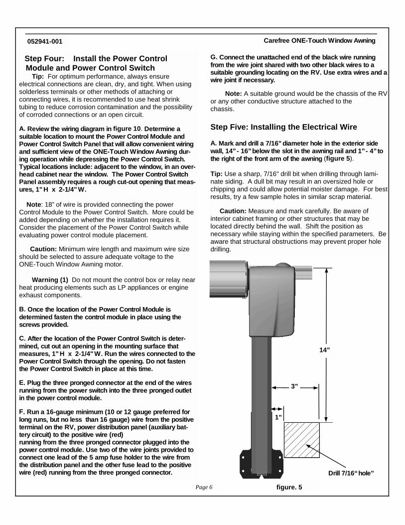
G. Connect the unattached end of the black wire running from the wire joint shared with two other black wires to a suitable grounding locating on the RV. Use extra wires and a wire joint if necessary. Note: A suitable ground would be the chassis of the RV or any other conductive structure attached to the chassis. Step Five: Installing the Electrical Wire A. Mark and drill a 7/16" diameter hole in the exterior side wall, 14” - 16” below the slot in the awning rail and 1” - 4” to the right of the front arm of the awning (figure 5). Tip: Use a sharp, 7/16" drill bit when drilling through lami-nate siding. A dull bit may result in an oversized hole or chipping and could allow potential moister damage. For best results, try a few sample holes in similar scrap material. Caution: Measure and mark carefully. Be aware of interior cabinet framing or other structures that may be located directly behind the wall. Shift the position as necessary while staying within the specified parameters. Be aware that structural obstructions may prevent proper hole drilling.
Carefree ONE-Touch Window Awning 052941-001
figure. 5
14”
Drill 7/16“ hole”
3”
1”
Page 6

Step Six: Verify Operation A. Fully extend the awning until the valance on the roller assembly points down. Note: (1) For Alumaguard models it may be necessary to assist the deployment of the awning away from the RV for steps 6A through 6F. Until the Hub and hook assembly is installed in step 3b. (2) If the motor runs in the reverse direction, it will be necessary to push the switch out of the Power Control Switch panel, flip it upside down and reinstall. (3) The Power Control Switch panel may now be mounted in place. Step Seven: Secure the Canopy Fabric To the Awning Rail A. Secure the canopy fabric or Alumaguard using one, #6 x 3/8" hex head screw at the front and back end of the awning ( figure 6 ). (requires 1/4” Nut Driver B. On Alumaguard awnings only, locate the Hook on the hub using the multiple teeth settings for positioning (as shown in figure 7 ) on each end of the roller assembly. With the awning fully retracted, extend the awning and verify that the Hooks are engaging the Alumaguard properly. When operating properly, the Hooks will engage the end of the Alumaguard cover and move it up and over the roller assembly.
B. Slide grommet over wire. Route the power cord from the motorized side of the awning through the hole in the side wall of the RV to the power control module . Use the wire joints provided to connect the two, 14-gauge wires to the two leads on the two pronged connector. Plug the two pronged connector into the two pronged outlet in the power control module. Tip: Conceal the wires behind corner trim molding or inside cabinets. If surface wiring is the only option, obtain aftermarket concealment raceways to safely route the wires. C. Apply silicon sealant or putty tape to the back of the flange of the Wall Bushing and place the Wall Bushing in the hole . Carefully trim excess sealant from ar ound the outlet Tip: Allow a downward loop to form in the wire from the Arm as it enters the side wall to prevent rainwater from
Page 7
Carefree ONE-Touch Window Awning 052941-001
B. Once position established insert a #6 x 1/2 self drilling screw (as shown in figure 8 ) to secure Hub and Hook in place.
Fabric
Alumaguard
#6 x 3/8" screw
Awning Rail
figure. 6
Polyrod
#6 x 3/8" screw

Section Two Operational Instructions
Tip: For optimum performance, be sure the battery systems are fully charged or the power converter energized.
How the Power Control Module Works To prevent damage to the ONE-Touch motor and circuitry, the Power Control Module monitors the current drawn by the motor. If the current draw exceeds the preset factory level, the power control module shuts off the power to the awning momentarily. This will occur if the power switch continues to be operated after the awning is fully retracted or extended. To reduce wear on the awning and it’s power system do not continuing to operate the power switch after full extension or retraction.
Step One: To Extend or Retract the Awning A. To Extend: Power Switch held in the “ ON” , position, op-erate the direction switch in the “ EXTEND” mode. Extend the window awning until the roller assembly stops turning. Valance position may be set where desired. Note: If the awning is only to be partially extended, simply release the momentary rocker switch when the awning is extended to the point desired. To retract the awning, operate the power switch and the direction switch in the “RETRACT” position until the awn-ing is fully retracted.
figure 9
Power Switch
Hook
Rolled up position
fabric
Alumaguard
Page 8
Carefree ONE-Touch Window Awning 052941-001
figure 7
Hub
figure 8
Slight gap between Hubs and Covers
#6 x 1/2 self drilling screw
Hook
Hub
Fasten Hub & Hook in place using one of the two holes available. Note: screw must be driven through hub and Roll Bar; if screw tip lands in Roll Bar grove use other hole in hook to drive screw.
Roll Bar

Page 9
Carefree ONE-Touch Window Awning 052941-001
figure 10
M
PX
GN
D
+12V
DC
MO
TO
R -
MO
TO
R +

Section Three Troubleshooting
PRODUCT: Carefree ONE-Touch Wi ndow Awning TITLE: ONE-Touch Window Awning Troubleshooting DOCUMENT: 052941-001 - 4/14/00
ONE-Touch Window Awning TROUBLE SHOOTIN G GUIDE PLEASE REVIEW THE FOLLOWING TO OBTAIN INFORMATION REGARDING SYMPTOMS, POSSIBLE CAUSES AND SOLUTIONS TO ONE-Touch AWNING PROBLEMS.
Page 10
SYMPTOM: WINDOW AWNING DOES NOT EXTEND
ž POSSIBLE CAUSE (1): Low battery
♦ PROBABLE SOLUTION (1): Charge battery
ž POSSIBLE CAUSE (2): Blown Fuse between the Power Control Module and the Power Supply.
♦ PROBABLE SOLUTION (2): Replace fuse
ž POSSIBLE CAUSE (3): Battery disconnect ž circuits open
♦ PROBABLE SOLUTION (3): Close battery ♦ disconnect circuits
ž POSSIBLE CAUSE (4): Incorrect wire ž connection, bad connections or bad grounds. ♦ PROBABLE SOLUTION (4): Refer to wiring
diagram for correct connections . Check all wiring connections and grounds and make sure there is good contact . Repair as necessary.
Carefree ONE-Touch Window Awning 052941-001
figure 11

Page 11
Rolled up Position
♦ ž POSSIBLE CAUSE (1): If an Alumaguard Awning, the traction masters may not be installed or are not installed correctly. ♦ PROBABLE SOLUTION (1): Install or adjust traction master as shown.
SYMPTOM: The Roller Assembly spins but will not extend away from the RV.
Alumaguard
Fabric
Hub and Hook Assembly
figure 12
Carefree ONE-Touch Window Awning 052941-001
Page 12
Á Periodically clean the fabric using a mild laundry detergent or an approved aftermarket awning or vinyl cleaner.
Á When using cleaners, be sure to follow the manufacturers instructions carefully.
Á Use only a soft brush for cleaning or scrubbing.
Á Be sure to clean both sides of the fabric and to rinse thoroughly.
Á Allow the fabric to dry completely before retracting the Carefree ONE-Touch Patio Awning. Do not use oil based cleaners or any caustic, granulated, or abrasive type cleaners on your Carefree ONE-Touch Patio Awning.
Á Replace any parts that become damaged.
Á Once per camping season, clean the contacts on the electrical harness and receptacle on the side of the RV.
Á Periodically check all mounting hardware, screws, lags, etc., for tightness. Re-tighten when necessary. Keep the arm assemblies clean and free of debris by periodically flushing them with low pressure water (avoid introducing water into the motorized and non-motorized housings).
ž Periodically apply dry silicone lubricant to both the arm assemblies and hardware beneath the motorized and non-motorized housings. žWhen storing the RV turn the switch key to the “OFF” position and remove the key.
Section Four Maintenance
Section Five Warranty Information CAREFREE OF COLORADO AWNINGS “TWO & FOUR” YEAR LIMITED WARRANTY
1. DURATION: Two years on parts, freight and labor on canopies; and four years parts, freight and labor on spring assemblies (or motors), rollers and hardware. Please retain dated proof of purchase (receipt). Warranty duration is not extended by the length of time the product is not in use or the time which purchaser is deprived the use of the product. The duration of coverage on parts and repairs provided as per this warranty shall be determined by the date of the original product purchase (not by the date of repairs). 2. PRODUCTS:. Warranty covers all Carefree of Colorado ONE-Touch, Spirit, Fiesta, Simplicity, patio awnings and all Carefree Window Awnings installed and operated as per Warrantor’s instructions. 3. WHO GIVES THIS WARRANTY (WARRANTOR); Carefree of Colorado a Scott Fetzer Company Telephone: 1-303-469-1152 Fax: 1-303-460-9106 2145 West 6th Avenue Broomfield, CO 80020 No other person or company is authorized to change or amend the Warrantor’s obligations set forth in this warranty.
4. WHO RECEIVES THIS WARRANTY (ORIGINAL PUR-CHASER): The first (“Original Purchaser”), other than for purposes of resale, of the Carefree of Colorado product that is properly installed and operated within the continental US and Canada. 5. WHAT IS COVERED UNDER THIS WARRANTY: Defects on the manufacturer’s material and workmanship of product under normal use, and which occur within the duration of the warranty period. On all awnings, the following parts are covered only as follows: a) Fabrics, free from quality defects (normal wear and fading are excluded); (b) Roller Tube, against extrusion defects; (c) Springs (or Motor) Assembly(ies), against breakage; and (d) Hardware, against extrusion defects. 6. WHAT IS NOT COVERED UNDER THIS WARRANTY: A. Fabric damage such as pinholes or tears not reported within ten (10) calendar days of purchase; B. Improper installation and/or any damage or failure that results from improper installation of the product, including fabric damage caused by improper installation; C. Product abuse and normal wear .
Carefree ONE-Touch Window Awning 052941-001
Page 13
D. Conditions that are not related to the material or work-manship of the product: including any failure that results from an accident, wind, rain , water pooling, or other acts of God; purchaser’s abuse; neglect; failure to operate, or use or maintain the product in accordance with the instructions provided in the Owner’s Manual supplied with the product; (failure to operate the product(s) in accordance with instructions in the Owner’s Manual and on the product shall also include the removal or alteration of any product component or device. In the event of any such removal or alteration, this warranty is void);
E. ANY INCIDENTAL, INDIRECT, OR CONSEQUENTIAL LOSS, DAMAGE, OR EXPENSE THAT MAY RESULT FROM ANY DEFECT, FAILURE, OR MALFUNCTION OF THE CAREFREE OF COLORADO PRODUCT. Some states do not allow the exclusion or limitation on incidental or consequential damages, so the above limitation or exclusion may not apply to you. F. Any failure that results from the use of another product with a Warrantor’s product that is not specifically approved by the Warrantor. 7. RESPONSIBILITIES OF WARRANTOR UNDER THIS WARRANTY: Repair or replace at Warrantor’s option, of the covered part(s) which Warrantor, in the exercise of its reasonable discretion, determines to be defective; provided that the Warrantor receives notice of the defect within the stated warranty period for that respective product/component . Warrantor w ill also pay the respective servicing dealer or agent for performing any repairs authorized by Warrantor as per the terms of this warranty. 8. RESPONSIBILITIES OF ORIGINAL PURCHASER UNDER THIS WARRANTY: A. Retain dated Proof of Purchase for specific product, and provide it as requested. B. Inspect the awning upon purchase to confirm the condition of the canopy and the proper operation of the product. C. Perform “Periodic Preventative Maintenance” as specified in Owners Manual. D. Deliver any product claimed or found defective during warranty period to the nearest Carefree of Colorado Authorized Service Dealer. The Original Purchaser is responsible for any expenses related to delivery or pick up of product to/from the Service Dealer . Visit carefreeofcolorado.com for the name of nearest Authorized Service Dealer, or call Carefree at the phone number shown above.
E. Use reasonable care in the operation and maintenance of the products as described in the Owner’s Manual sup-plied with the product(s). 9. WHEN WARRANTOR WILL PERFORM REPAIR OR REPLACEMENT UNDER WARRANTY. A. Repair or replacement w ill be scheduled and performed according to normal work flow at the nearest Authorized Service Dealer, and depending on the availability of replacement parts. B. If the purchaser does not receive satisfactory results from the Authorized Service Dealer, the purchaser should contact the Carefree of Colorado Customer Service Department (see paragraph 2). THIS WARRANTY GIVES YOU SPECIFIC LEGAL RIGHTS AND YOU MAY ALSO HAVE OTHER RIGHTS WHICH VARY FROM STATE TO STATE. No action to enforce this warranty shall be commenced later than ____30___ days expiration of the warranty period. The Duration of this Limited Warranty also limits the duration of any implied warranty such as warranty of merchantability or fitness for a particular use or purpose . Some states do not allow such limitations so the implied warranty limitation may not apply to you. Carefree of Colorado reserves the right to change the specifications and design of any product without notice and with no obligation to make corresponding changes to products previously manufactured.
Carefree ONE-Touch Window Awning 052941-001


![Algebra II - Quadratics Update [Read-Only] · Graphing Quadratic Function ... You have made a rectangular stained glass window that is 2 feet by 4 feet. You have 7 square feet of](https://img.dokumen.tips/doc/110x75/5e94481472569840496355db/algebra-ii-quadratics-update-read-only-graphing-quadratic-function-you-have.jpg)