Embed Size (px)
Citation preview

de Einbau- und Betriebsanleitung
en Installation and operating instructions
fr Notice de montage et de mise en service
nl Inbouw- en bedieningsvoorschriften
Wilo-SiBoost Smart 1Wilo-Comfort-Vario COR-1 ...-GE, .../VR
2 5
35
45
9-E
d.0
2 /
20
13
-0
7-
Wilo
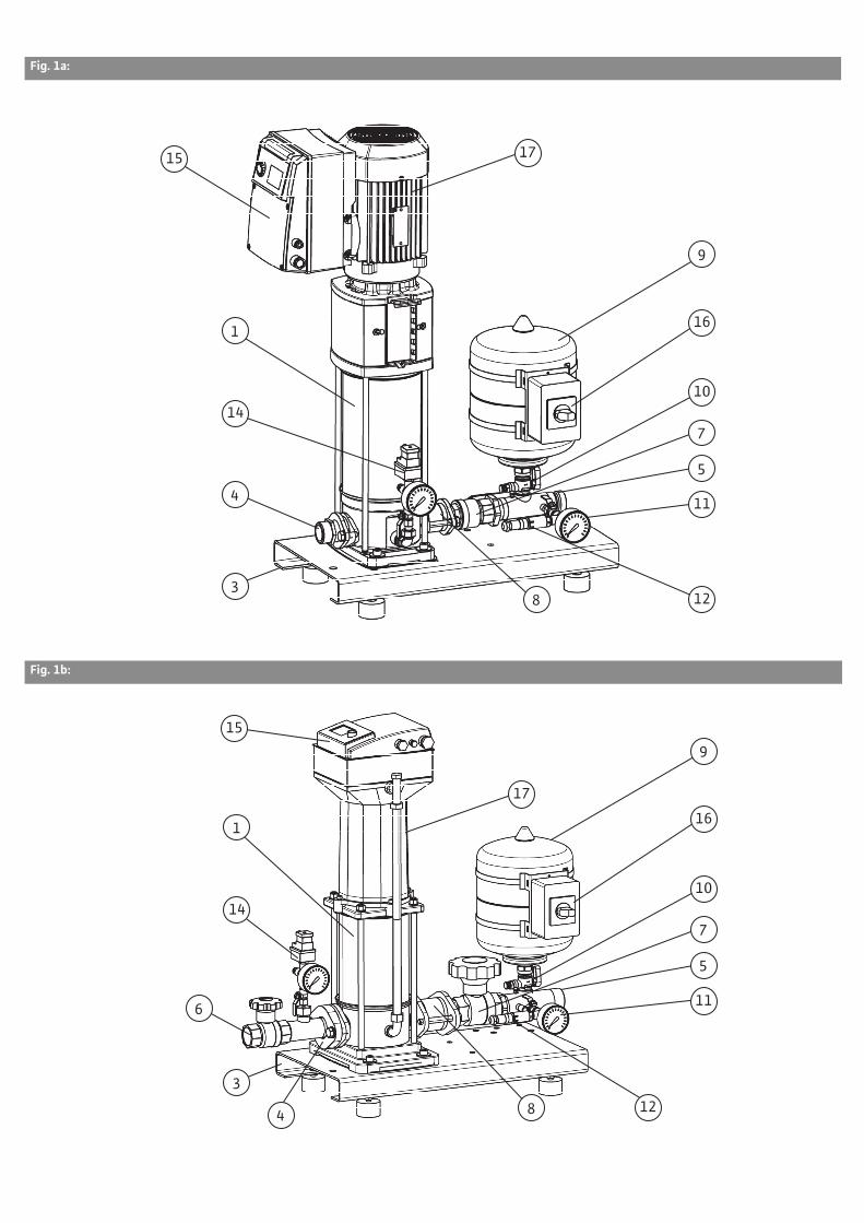
Fig. 1a:
Fig. 1b:
3
1
4
5
7
8
9
12
11
14
15 17
10
16
3
1
4
5
7
8
9
12
11
14
15
17
10
16
6

Fig. 1c:
3
1
4
5
7
8
9
12
11
14
15 17
10
16
Fig. 1d:
3
1
5 7
8
9
12
11
14
15
17
10
16
4
6
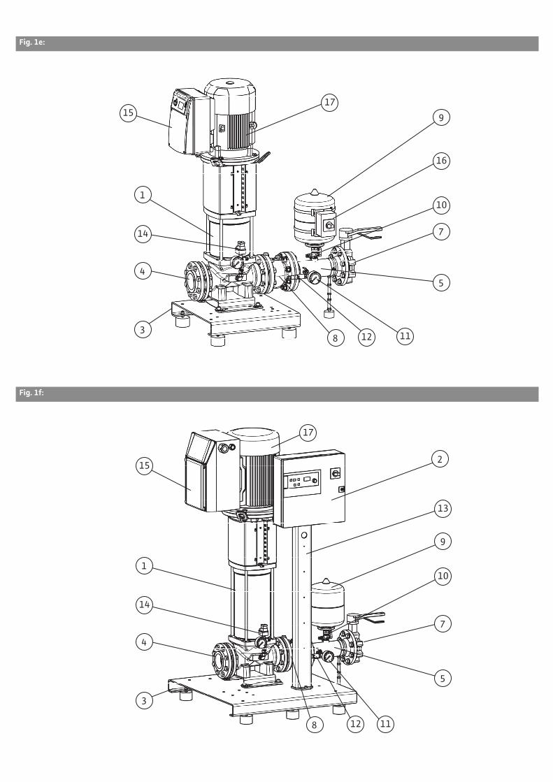
Fig. 1e:
3
1
4 5
7
8
9
12 11
14
15 17
10
16
Fig. 1f:
3
1
4
5
7
8
9
12 11
14
15
17
10
13
2

Fig. 2:
11
18
12a
19
9
1012b
12b

Fig. 3:
OPEN
CLOSED
9
10
A
B
C

Fig. 4:
Fig. 5a:
14a
14b
14-1
14-4
14-2
14-3
14-5
14-6
14-814-914-7
14-10
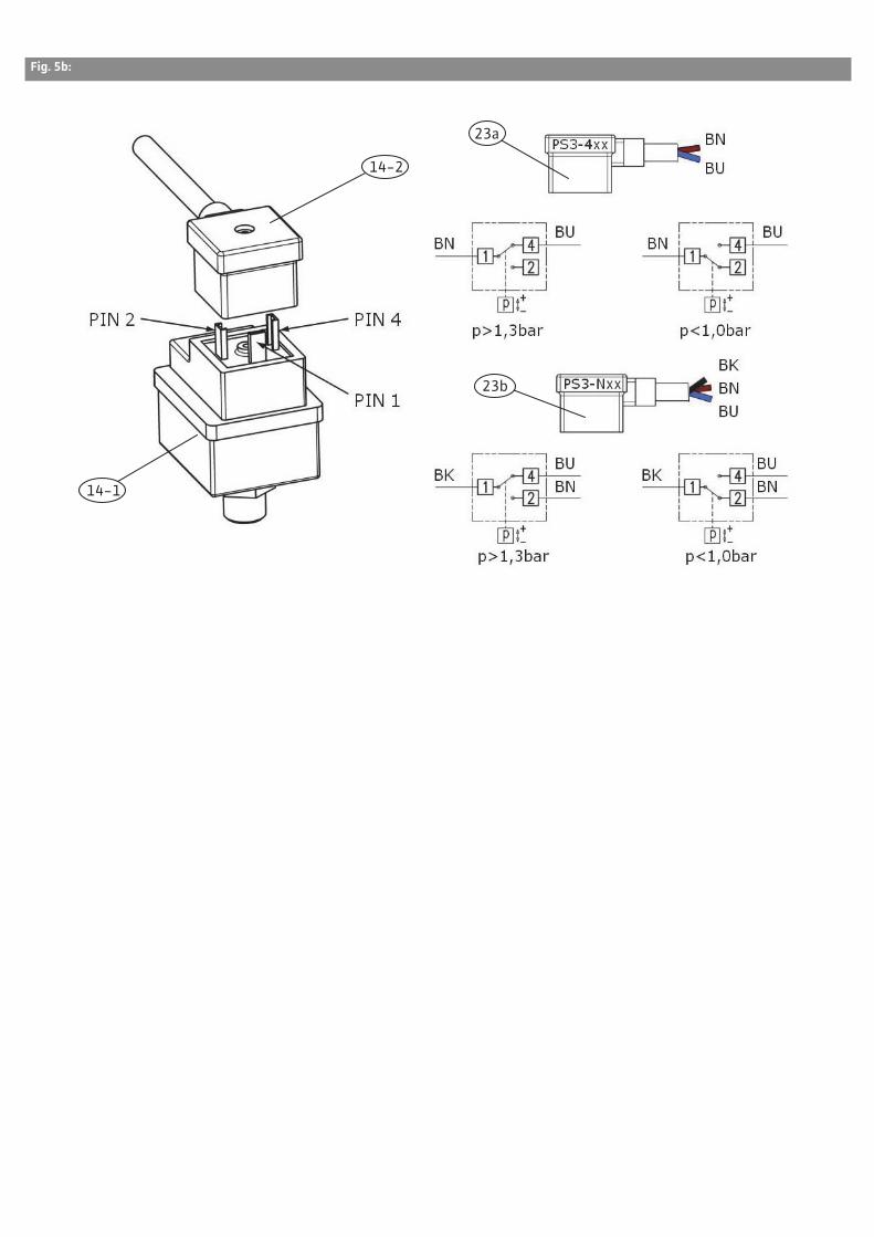
Fig. 5b:
14-2
23a
23b
14-1
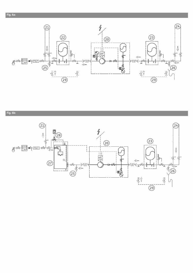
Fig. 6a:
20
21 24
22 23
25 26
29 29
Fig. 6b:
20 23
27
28
25 26
29
21 24

Fig. 7:
RB
30
31
32
30
32 34
333133
16
16

Fig. 8a:
x2
36
37
38
39
42
41
40
35

Fig. 8b:
x4
x4
x4 oder
x6
36
37 42
2
38
35
39
34
35
41
40

Fig. 9a:
44 45 49 50
43
50
47
48
46

Fig. 9b:
52


de Einbau- und Betriebsanleitung7
en Installation and operating instructions31
fr Notice de montage et de mise en service53
nl Inbouw- en bedieningsvoorschriften77

English
26 WILO SE 07/2013
Captions
Fig. 1a Example SiBoost Smart
1HELIX VE606
Fig. 1b Example COR-1MVISE806-
2G-GE
Fig. 1c Example COR-
1MVIE204EM2-GE
Fig. 1d Example COR-1MHIE406-
2G-GE
Fig. 1e Example COR-1HELIX
VE5202-GE
Fig. 1f Example COR-1HELIX
VE5204/VR
1 Pump
2 Control device (for some types)
3 Base frame
4 Inlet connection
5 Pressure pipe
6 Shut-off device on inlet side (optionally for some types)
7 Shut-off device on pressure side
8 Non-return valve
9 Diaphragm pressure vessel
10 Throughflow fitting
11 Pressure gauge
12 Pressure sensor
13 Mounting bracket for the fixation of the control device (for some types)
14 Low-water cut-out switch-gear (WMS) (optional)
15 Frequency converter
16 Main switch (MS) (optional)
17 Motor
Fig. 2 Pressure sensor and
diaphragm pressure vessel
kit
9 Diaphragm pressure vessel
10 Throughflow fitting
11 Pressure gauge
12a Pressure sensor
12b Electrical connection, pres-sure sensor
18 Draining/venting
19 Stop valve
Fig. 3 Operation of throughflow
fitting/pressure test
Diaphragm pressure vessel
9 Diaphragm pressure vessel
10 Throughflow fitting
A Opening/closing
B Drain
C Checking the supply pres-sure
Fig. 4 Information table: nitrogen
pressure, diaphragm
pressure vessel (example)
a Nitrogen pressure according to the table
b Switch-on pressure, base-load pump, in bar PE
c Nitrogen pressure in bar PN2
d Nitrogen measurement without water
e Important! Introduce nitro-gen only
Fig. 5a Low-water cut-out
switchgear kit (WMS)
Fig. 5b Electric connection options /
switching logic WMS
14-a WMS kit
14-1 PS3 pressure switch
14-2 PS3-Nxx or PS3-4xx plug
14-3 Pressure gauge
14-4 Distributor
14-5 Ventilation valve
14-6 Stop valve
14-b WMS connection kit
14-7 Screwed connection
14-8 Fitting
14-9 Pump drainage screw
14-10 O-ring seals
PS3-4xx Two-core connection cable, normally-closed function (opens when pressure drops)
PS3-Nxx Three-core connection cable, two-way-switch function
BN Brown
BU Blue
BK Black
Connection in control device (see supplied terminal dia-gram)

English
Installation and operating instructions Wilo-SiBoost Smart 1, Wilo-Comfort-Vario COR-1 ...-GE, .../VR 27
Fig. 6a Example of a direct
connection (hydraulic
diagram)
Fig. 6b Example of an indirect
connection (hydraulic
diagram)
20 SiBoost Smart1/COR-1… system
21 Consumer connections upstream of the system
22 Diaphragm pressure vessel (accessory) on the inlet side with bypass
23 Diaphragm pressure vessel (accessory) on the pressure side with bypass
24 Consumer connections downstream of the system
25 Infeed connection for flush-ing the system
26 Drainage connection for flushing the system
27 Non-pressurised break tank (accessory) on the inlet side
28 Flushing apparatus for inlet connection of the break tank
29 Bypass for inspection/main-tenance only (not perma-nently installed)
Fig. 7 Installation example
16 Main switch (MS) (optional)
30 Compensator with exten-sion limiters (accessory)
31 Flexible connection pipe (accessory)
32 Floor fixation with struc-ture-borne noise insulation (by the customer)
33 Fixation of pipes, e.g. with pipe clips (by the customer)
34 Screw the vibration absorb-ers (included in scope of delivery) into the threaded inserts provided and secure them with counter nuts
BW Bend angle for flexible con-nection pipe
RB Bend radius for flexible con-nection pipe
Fig. 8a Transport information
example for system
without control device
(up to 7.5 kW)
Fig. 8b Transport information
example for system with
control device
(> 7.5 kW)
2 Control device
34 Screw the vibration absorb-ers (included in scope of delivery) into the threaded inserts provided and secure them with counter nuts
35 Eyebolts/transport eyes for the attachment of lifting gear
36 Transport pallet/transport frame (example)
37 Transport equipment - (example - pallet truck)
38 Transport securing (screws)
39 Transport securing (strap)
40 Lifting device (example – crane gear (Fig. 8a), load bar (Fig. 8b)
41 Securing against overturning (lifting strap example)
42 Carton/bag with accesso-ries/accessories kit (e.g. dia-phragm pressure vessel, counter flanges, vibration absorbers etc.)
Fig. 9a Break tank
(accessory - example)
43 Inlet (with float valve (accessory))
44 Air supply/venting with insect protection
45 Inspection opening
46 Overflow Ensure adequate drainage. Protect siphon or valve against ingress of insects. No direct connection to the sewer system (free drainage according to EN 1717)
47 Draining
48 Extraction (connection for pressure boosting system)
49 Terminal box for low-water signal transmitter
50 Connection for flushing apparatus intake
51 Level display
English
28 WILO SE 07/2013
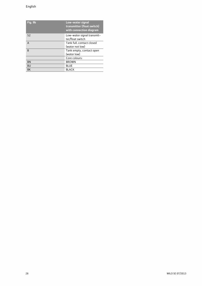
Fig. 9b Low-water signal
transmitter (float switch)
with connection diagram
52 Low-water signal transmit-ter/float switch
A Tank full, contact closed (water not low)
B Tank empty, contact open (water low)
Core colours:
BN BROWN
BU BLUE
BK BLACK

English
Installation and operating instructions Wilo-SiBoost Smart 1, Wilo-Comfort-Vario COR-1 ...-GE, .../VR 29

English
30 WILO SE 07/2013
1 General ..................................................................................................................................................31
2 Safety ....................................................................................................................................................312.1 Indication of instructions in the operating instructions .................................................................................312.2 Personnel qualifications ......................................................................................................................................312.3 Danger in the event of non-observance of the safety instructions ..............................................................312.4 Safety consciousness on the job ........................................................................................................................312.5 Safety instructions for the operator .................................................................................................................312.6 Safety instructions for installation and maintenance work ...........................................................................322.7 Unauthorised modification and manufacture of spare parts ..........................................................................322.8 Improper use ........................................................................................................................................................32
3 Transport and interim storage ...........................................................................................................32
4 Intended use .........................................................................................................................................33
5 Product information ............................................................................................................................345.1 Type key ................................................................................................................................................................345.2 Technical data 355.3 Scope of delivery .................................................................................................................................................365.4 Accessories ...........................................................................................................................................................36
6 Description of the product and accessories .....................................................................................366.1 General description .............................................................................................................................................366.2 Components of the system ................................................................................................................................366.3 Function of the system .......................................................................................................................................376.4 Noise .....................................................................................................................................................................38
7 Setup/installation ................................................................................................................................387.1 Installation site ....................................................................................................................................................387.2 Installation ............................................................................................................................................................387.2.1 Foundation/bearing surface ...............................................................................................................................387.2.2 Hydraulic connection and pipes .........................................................................................................................387.2.3 Hygiene (TrinkwV 2001) .....................................................................................................................................387.2.4 Protection against dry running/low water level (accessory) ..........................................................................397.2.5 Main switch (accessories) ...................................................................................................................................397.2.6 Diaphragm pressure tank (accessory) ...............................................................................................................397.2.7 Safety valve (accessory) .....................................................................................................................................407.2.8 Non-pressurised break tank (accessory) ..........................................................................................................407.2.9 Expansion joints (accessories) ............................................................................................................................407.2.10Flexible connection lines (accessory) ...............................................................................................................417.2.11Pressure reducer (accessory) .............................................................................................................................417.3 Electrical connection ...........................................................................................................................................41
8 Commissioning/decommissioning .....................................................................................................428.1 General preparations and control measures .....................................................................................................428.2 Protection against low water level (WMS) ........................................................................................................428.3 Commissioning the system .................................................................................................................................428.4 Decommissioning the system ............................................................................................................................43
9 Maintenance .........................................................................................................................................43
10 Faults, causes and remedies ...............................................................................................................43
11 Spare parts ...........................................................................................................................................46
English
Installation and operating instructions Wilo-SiBoost Smart 1, Wilo-Comfort-Vario COR-1 ...-GE, .../VR 31
Installation and operating instructions1 General
About this document:
The language of the original operating instruc-
tions is German. All other languages of these
instructions are translations of the original oper-
ating instructions.
These installation and operating instructions are
an integral part of the product. They must be kept
readily available at the place where the product is
installed. Strict adherence to these instructions is
a precondition for the proper use and correct
operation of the product.
These installation and operating instructions cor-
respond to the relevant version of the product and
the underlying safety regulations and standards
valid at the time of going to print.
EC declaration of conformity:
A copy of the EC declaration of conformity is a
component of these operating instructions.
If a technical modification is made on the designs
named there without our agreement or the decla-
rations made in the installation and operating
instructions on product/personnel safety are not
observed, this declaration loses its validity.
2 SafetyThese operating instructions contain basic infor-
mation which must be adhered to during installa-
tion, operation and maintenance. For this reason,
these operating instructions must, without fail, be
read by the service technician and the responsible
specialist/operator before installation and com-
missioning.
It is not only the general safety instructions listed
under the main point “safety” that must be
adhered to but also the special safety instructions
with danger symbols included under the following
main points.
2.1 Indication of instructions in the operating
instructions
Symbols:
General danger symbol
Danger due to electrical voltage
NOTE
Signal words:
DANGER!
Acutely dangerous situation.
Non-observance results in death or the most
serious of injuries.
WARNING!
The user can suffer (serious) injuries. “Warning”
implies that (serious) injury to persons is proba-
ble if this information is disregarded.
CAUTION!
There is a risk of damaging the product/unit.
“Caution” implies that damage to the product is
likely if this information is disregarded.
NOTE:
Useful information on handling the product. It
draws attention to possible problems.
Information that appears directly on the product,
such as:
• Direction of rotation arrow,
• Identification for connections,
• Rating plate,
• Warning sticker,
must be strictly complied with and kept in legible
condition.
2.2 Personnel qualifications
The installation, operating and maintenance per-
sonnel must have the appropriate qualifications
for this work. Area of responsibility, terms of ref-
erence and monitoring of the personnel are to be
ensured by the operator. If the personnel are not in
possession of the necessary knowledge, they are
to be trained and instructed. This can be accom-
plished if necessary by the manufacturer of the
product at the request of the operator.
2.3 Danger in the event of non-observance of the
safety instructions
Non-observance of the safety instructions can
result in risk of injury to persons and damage to
the environment and the product/unit. Non-
observance of the safety instructions results in
the loss of any claims to damages.
In detail, non-observance can, for example, result
in the following risks:
• Danger to persons from electrical, mechanical and
bacteriological influences
• Damage to the environment due to leakage of
hazardous materials
• Property damage
• Failure of important product/unit functions
• Failure of required maintenance and repair proce-
dures
2.4 Safety consciousness on the job
The safety instructions included in these installa-
tion and operating instructions, the existing
national regulations for accident prevention
together with any internal working, operating and
safety regulations of the operator are to be com-
plied with.
2.5 Safety instructions for the operator
This appliance is not intended for use by persons
(including children) with reduced physical, sensory
or mental capabilities, or lack of experience and
knowledge, unless they have been given supervi-
sion or instruction concerning use of the appliance
by a person responsible for their safety.
Children should be supervised to ensure that they
do not play with the appliance.

English
32 WILO SE 07/2013
• If hot or cold components on the product/the unit
lead to hazards, local measures must be taken to
guard them against touching.
• Guards protecting against touching moving com-
ponents (such as the coupling) must not be
removed whilst the product is in operation.
• Leakages (e.g. from the shaft seals) of hazardous
fluids (which are explosive, toxic or hot) must be
led away so that no danger to persons or to the
environment arises. National statutory provisions
are to be complied with.
• Highly flammable materials are always to be kept
at a safe distance from the product.
• Danger from electrical current must be eliminated.
Local directives or general directives [e.g. IEC, VDE
etc.] and instructions from local energy supply
companies must be adhered to.
2.6 Safety instructions for installation and
maintenance work
The operator must ensure that all installation and
maintenance work is carried out by authorised and
qualified personnel, who are sufficiently informed
from their own detailed study of the operating
instructions.
Work on the product/unit must only be carried out
when at a standstill. It is mandatory that the pro-
cedure described in the installation and operating
instructions for shutting down the product/unit
be complied with.
Immediately on conclusion of the work, all safety
and protective devices must be put back in posi-
tion and/or recommissioned.
2.7 Unauthorised modification and manufacture of
spare parts
Unauthorised modification and manufacture of
spare parts will impair the safety of the product/
personnel and will make void the manufacturer's
declarations regarding safety.
Modifications to the product are only permissible
after consultation with the manufacturer. Original
spare parts and accessories authorised by the
manufacturer ensure safety. The use of other
parts will absolve us of liability for consequential
events.
2.8 Improper use
The operating safety of the supplied product is
only guaranteed for conventional use in accord-
ance with Section 4 of the operating instructions.
The limit values must on no account fall under or
exceed those specified in the catalogue/data
sheet.
3 Transport and interim storageThe pressure boosting system is supplied on one
or more pallets or wooden transport frames (see
examples in Fig. 8a and 8b), on transport boards or
in a crate and is film-wrapped to protect it against
moisture and dust. Transport and storage instruc-
tions applied to the packaging must be observed.
CAUTION! Risk of property damage!
Use approved lifting gear to transport the unit
(Fig. 8a and 8b). Ensure the stability of the load
since, with this particular pump design, the cen-
tre of gravity is shifted to the top (top-heavy).
Connect transport slings or ropes to the trans-
port eyes provided (see Fig. 8a and 8b - item 35)
or around the base frame. The pipes are not suit-
able to withstand loads and should not be used
to secure loads in transit.
CAUTION! Risk of damage!
Subjecting the pipes and valves to loads while in
transit can result in leakages!
The transport dimensions, weights and necessary
passageways and transport areas of the system
can be taken from the supplied installation plan or
other documentation.
CAUTION! Risk of detriment or damage!
The system must be protected by means of suit-
able measures against moisture, frost and heat
and also mechanical damage!
When receiving and unpacking the pressure
boosting system and the supplied accessories,
first check the packaging for damage.
If damage is found which may have been caused
by dropping the system or the like:
• Check the pressure boosting system and accesso-
ries for possible damage.
• Inform the delivery company (forwarding agent)
or our customer service even if you do not find any
obvious damage to the system or its accessories.
After removing the packaging, store or install the
system according to the described installation
conditions (see section titled Installation).
English
Installation and operating instructions Wilo-SiBoost Smart 1, Wilo-Comfort-Vario COR-1 ...-GE, .../VR 33
4 Intended useWilo pressure boosting systems of the WILO
SiBoost-Smart -1… and COR-1MVIE… series are
designed for water-supply systems which do
without a standby pump. They are used for pres-
sure boosting and pressure maintenance in com-
mercial and private areas, such as for:
• Domestic water supply and cooling systems.
• Industrial water supply and cooling systems.
• Fire water supply systems for self-help without
any normative specifications.
• Irrigation and sprinkling installations.
• The following standards and directives should be
observed during planning and installation:
• DIN 1988 (for Germany)
• DIN 2000 (for Germany)
• EU directive 98/83/EC
• Potable water ordinance - TrinkwV2001
(for Germany)
• DVGW directives (for Germany),
Make sure that the fluid to be pumped in the
system will not corrode the materials used in
the system either chemically or mechanically
and that it does not contain any abrasive or
long-fibre constituents.
Automatically controlled pressure boosting sys-
tems are supplied from the public potable water
supply network either directly (connected
directly) or indirectly (connected indirectly) via
a break tank. These break tanks are sealed but
are not pressurised, i.e. they are under only
atmospheric pressure.

English
34 WILO SE 07/2013
5 Product information
5.1 Type key
Example: SiBoost Smart 1HELIX VE606
Wilo Brand name
SiBoost Product family: pressure boosting systems
Smart Series designation
1 Number of pumps
HELIX Pump series designation (see sup-plied pump documentation)
-VE Pump design, vertical standard ver-sion
6 Rated flow rate of pump Q [m3/h]
06 Number of pump stages
Example: COR-1MVIE406-2G-GE
CO COmpact pressure boosting system
R Regulation (control) by frequency converter
1 With one pump
MVIE Pump series designation (see also supplied pump documentation)
4 Rated flow rate of pump Q [m3/h]
06 Number of pump stages
-2G Generation specification
GE GrundEinheit (basic unit), i.e. without an additional control deviceControlled by the pump's integrated frequency converter
Example: COR-1MVISE806-2G-GE
CO COmpact pressure boosting system
R Regulation (control) by frequency converter
1 With one pump
MVISE Pump series designation (see also supplied pump documentation)
8 Rated flow rate of pump Q [m3/h]
06 Number of pump stages
-2G Generation specification
GE GrundEinheit (basic unit), i.e. without an additional control deviceControlled by the pump's integrated frequency converter
Example: COR-1HELIX VE5203/3/VR
CO COmpact pressure boosting system
R Regulation (control) by frequency converter
1 With one pump
HELIX-VE Pump series designation (see also supplied pump documentation)
52 Rated flow rate of pump Q [m3/h]
03 Number of pump stages
/3 Number of reduced stages
VR Control device, in this case Vario Regler (controller)
Example: COR-1MHIE406-2G-GE
CO COmpact pressure boosting system
R Regulation (control) by frequency converter
1 With one pump
MHIE Pump series designation (see alsosupplied pump documentation)
4 Rated flow rate of pump Q [m3/h]
06 Number of pump stages
-2G Generation specification
GE GrundEinheit (basic unit), i.e. without an additional control deviceControlled by the pump's integrated frequency converter
Example: COR-1MVIE204EM2-GE
CO COmpact pressure boosting system
R Regulation (control) by frequency converter
1 With one pump
MVIE Pump series designation (see also supplied pump documentation)
2 Rated flow rate of pump Q [m3/h]
04 Number of pump stages
EM2 Single-phase version with preset operating mode 2 – pressure control mode
GE GrundEinheit (basic unit), i.e. without an additional control deviceControlled by the pump's integrated frequency converter
Additional designations for additional options
pre-installed at the factory
WMS Including WMS kit (low-water cut-out switchgear for operation with supply pressure)
HS Including main switch for switching the system on and off (power cut-off switch)
English
Installation and operating instructions Wilo-SiBoost Smart 1, Wilo-Comfort-Vario COR-1 ...-GE, .../VR 35
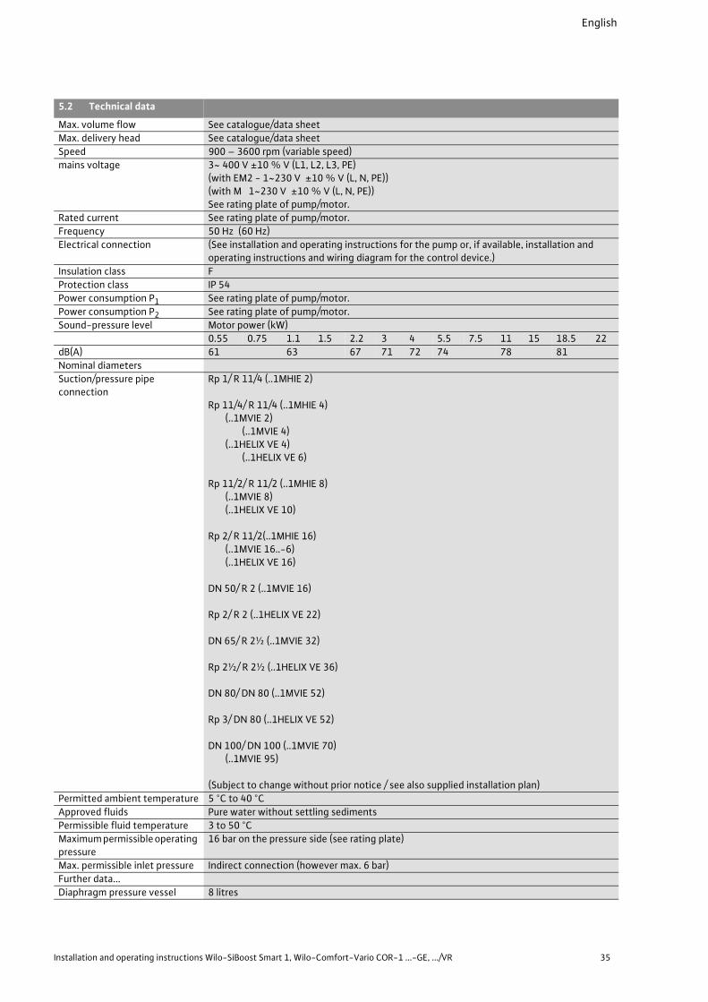
5.2 Technical data
Max. volume flow See catalogue/data sheet
Max. delivery head See catalogue/data sheet
Speed 900 – 3600 rpm (variable speed)
mains voltage 3~ 400 V ±10 % V (L1, L2, L3, PE)(with EM2 - 1~230 V ±10 % V (L, N, PE))(with M 1~230 V ±10 % V (L, N, PE))See rating plate of pump/motor.
Rated current See rating plate of pump/motor.
Frequency 50 Hz (60 Hz)
Electrical connection (See installation and operating instructions for the pump or, if available, installation and operating instructions and wiring diagram for the control device.)
Insulation class F
Protection class IP 54
Power consumption P1 See rating plate of pump/motor.
Power consumption P2 See rating plate of pump/motor.
Sound-pressure level Motor power (kW)
0.55 0.75 1.1 1.5 2.2 3 4 5.5 7.5 11 15 18.5 22
dB(A) 61 63 67 71 72 74 78 81
Nominal diameters
Suction/pressure pipe connection
Rp 1/ R 11/4 (..1MHIE 2)
Rp 11/4/ R 11/4 (..1MHIE 4) (..1MVIE 2)
(..1MVIE 4) (..1HELIX VE 4)
(..1HELIX VE 6)
Rp 11/2/ R 11/2 (..1MHIE 8)(..1MVIE 8)(..1HELIX VE 10)
Rp 2/ R 11/2(..1MHIE 16)(..1MVIE 16..-6)(..1HELIX VE 16)
DN 50/ R 2 (..1MVIE 16)
Rp 2/ R 2 (..1HELIX VE 22)
DN 65/ R 2½ (..1MVIE 32)
Rp 2½/ R 2½ (..1HELIX VE 36)
DN 80/ DN 80 (..1MVIE 52)
Rp 3/ DN 80 (..1HELIX VE 52)
DN 100/ DN 100 (..1MVIE 70)(..1MVIE 95)
(Subject to change without prior notice / see also supplied installation plan)
Permitted ambient temperature 5 °C to 40 °C
Approved fluids Pure water without settling sediments
Permissible fluid temperature 3 to 50 °C
Maximum permissible operating pressure
16 bar on the pressure side (see rating plate)
Max. permissible inlet pressure Indirect connection (however max. 6 bar)
Further data...
Diaphragm pressure vessel 8 litres

English
36 WILO SE 07/2013
5.3 Scope of delivery
• Pressure boosting system,
• Box with accessories/accessories kit/add-on parts
(Fig. 8a and 8b, item 42) if applicable
• Installation and operating instructions for the
pressure boosting system
• Installation and operating instructions for the
pumps
• Factory acceptance test certificate (in accordance
with EN 10204 3.1.B)
• Installation and operating instructions for the
control device if applicable
• Installation plan if applicable
• Electrical wiring diagram if applicable
• Installation and operating instructions for the fre-
quency converter if applicable
• Additional sheet with the factory setting of the
frequency converter if applicable
• Installation and operating instructions for the sig-
nal transmitter if applicable
• Spare parts list if applicable
5.4 Accessories
Accessories must be ordered separately as
required. The accessories from the Wilo range
include the following:
• Open break tank (example Fig. 10a),
• Larger diaphragm pressure vessel (on the suction
or discharge side)
• Safety valve
• Dry-running protection system:
• Protection against low water level (WMS) (Fig.
5a and 5b) in inlet mode (at least 1.0 bar) (sup-
plied fitted to the pressure boosting system if
part of the order)
• Float switch
• Low-water warning electrodes with level con-
trol relay
• Electrodes for tank operation (special accesso-
ries on request)
• Main switch (Fig. 1a to 1f ; Fig. 8 – 16;)
• Flexible connection lines (Fig. 7 – 31)
• Expansion joints (Fig. 7 – 30)
• Threaded flanges
• Sound-insulating casing (special accessories on
request)
6 Description of the product and accessories
6.1 General description
The system with its non-self-priming, vertically
(MVIE, MVISE or Helix VE) or horizontally (MHIE)
mounted high-pressure multistage centrifugal
pump is supplied with all pipework installed as a
compact unit ready for connection. The only con-
nections that have to be made are for the inlet and
pressure pipes and the electrical mains connec-
tion. Systems of the COR-1 and SiBoost Smart-1..
series (examples in Fig.1a to 1f) are installed on a
galvanized steel base frame (3) with vibration
absorbers (34).
It may also be necessary to install the supplied
accessories ordered separately.
The systems can be connected to the water sup-
ply network either directly (diagram in Fig. 6a) or
indirectly (diagram in Fig. 6b). When supplied with
a self-priming pump (special version), it may be
connected to the public water supply network
only indirectly (system separation by a non-pres-
surised break tank). Information on the pump type
used can be taken from the supplied installation
and operating instructions for the pump.
Observe the relevant, applicable regulations and
standards when using the potable water supply
and/or fire extinguishing supply. The systems
must be operated and maintained in accordance
with the relevant provisions (according to DIN
1988 (DVGW) in Germany) to ensure the perma-
nent operational reliability of the water supply
and prevent neither the public water supply nor
other consumer installations from being detri-
mentally affected. The respective applicable
standards or directives (see application under sec-
tion “Intended use”) on the connection and type
of connection to public water supply networks are
to be observed. They may be supplemented by
regulations of the water supply companies
(WVU) or the responsible fire protection author-
ity. In addition, the local conditions (e.g. a supply
pressure that is too high or fluctuating considera-
bly and which might require the installation of a
pressure relief) must also be observed.
6.2 Components of the system
The system comprises several main components,
which are described in the following. The scope of
delivery includes separate installation and operat-
ing instructions for the relevant operating parts/
components (see also supplied installation plan).
Mechanical and hydraulic system components
(Fig. 1a to 1f):
The system is installed on a base frame(3) with
vibration absorbers (34). It comprises a high-pres-
sure multistage centrifugal pump (1) with a three-
phase AC motor with an integrated frequency
converter (15), with a shut-off device (7) and a
non-return valve (8) installed on the pressure side.
There is also an assembly that can be shut off with
a pressure sensor (12) and pressure gauge (11) as
well as an 8-litre diaphragm pressure vessel (9)
with a throughflow fitting (10) that can be shut off
(for throughput according to DIN 4807, part 5).
A low-water cut-out switchgear (WMS) (14) can
be optionally installed or retrofitted on the pump's
drainage port or on the inlet pipe (see also Fig. 5a
and 5b).
An optional main switch (16) is pre-installed at the
factory and pre-wired with the motor of the pump
for systems of the COR-1…GE-HS or SiBoost
Smart1..-HS series. In this case the electrical con-
nection must be established by means of this
switch (see section “Electrical connection”).

English
Installation and operating instructions Wilo-SiBoost Smart 1, Wilo-Comfort-Vario COR-1 ...-GE, .../VR 37
The scope of delivery of systems of the COR-
1…VR series includes a control device (2) which is
installed on the base frame by means of a standing
console and ready wired with the electrical com-
ponents of the system.
These installation and operating instructions
describe the overall system in general only with-
out going into a detailed description of the opera-
tion of the optional control device (see Section 7.3
and the accompanying documentation for the
control device).
High-pressure multistage centrifugal pump (1)
with three-phase AC motor (17) and frequency
converter (15):
Different types of high-pressure multistage cen-
trifugal pumps are installed in the system depend-
ing on the application and the performance
parameters required. Information on the pump
and the setting and operation of the frequency
converter is provided by the supplied installation
and operating instructions.
Pressure sensor/diaphragm pressure vessel kit
(Fig. 2):
Consists of:
• Diaphragm pressure vessel (9) with throughflow
fitting (10)
• Pressure gauge (11)
• Pressure sensor (12a)
• Electrical connection, pressure sensor (12b)
• Draining/venting (18)
• Stop valve (19)
Control device VR (2):
The VR CVV control device is used to control and
regulate some types of systems. Information on
this control device is provided by the separate
installation and operating instructions supplied
for this purpose.
• Systems of series COR-1...GE or SiBoost Smart-1…
do not have a separate control device. The system
is controlled by the pump's integrated frequency
converter (15). You can find out how to operate
and handle the pump in the respective installation
and operating instructions.
6.3 Function of the system
Systems of the Wilo-Comfort-Vario or Wilo-
SiBoost-Smart-1… series are equipped as a stand-
ard with a non self-priming horizontal or vertical
high-pressure multistage centrifugal pump with
three-phase AC motor(17) and integrated fre-
quency converter (15). The pump is supplied with
water via the inlet connection (4).
For suction mode from lower-lying tanks, a sepa-
rate, vacuum-proof and pressure-resistant suc-
tion line with a foot valve should be installed. It
should be positioned at a constant upward incli-
nation from the tank to the pump connection.
The pump increases the pressure and pumps the
water to the consumer through the pressure pipe
(5). It is switched on and off and controlled pres-
sure-dependently for this purpose. A pressure
sensor (12) (see also Fig. 2) is used to monitor the
pressure. The pressure sensor continuously meas-
ures the actual pressure value, converts it into an
analogue current signal and transmits it to the fre-
quency converter (15) of the pump or to the exist-
ing control device (2). Depending on the demand
and the control mode, the frequency converter or
control device switches the pump on or off or
changes the speed of the pump until the set con-
trol parameters are reached For a more precise
description of the control mode, control process
and setting options, refer to the installation and
operating instructions for the pump or control
device.
The diaphragm pressure vessel installed (9) (total
capacity of approx. 8 litres) exercises a certain
buffer effect on the pressure sensor and prevents
oscillation of the control when switching the
pump on and off. However, it also allows small
amounts of water to be extracted (e.g. due to
smallest leakages) from the available storage vol-
ume without switching on the pump. This reduces
the switching frequency and stabilises the operat-
ing state of the system.
CAUTION! Risk of damage!
To protect the mechanical seal or plain bearings,
do not allow the pumps to run dry. Leakages may
be caused by a pump running dry.
A device for protection against low water level
(WMS) (14) (for details, see Fig. 5a and 5b) is pro-
vided as an accessory for direct connection to the
public water supply network. It monitors the
existing supply pressure and sends a switching
signal which is processed by the frequency con-
verter or control device. The WMS kit is installed
on the pump's drainage opening (an additional
WMS connection kit (Fig. 5a, 14b) from the acces-
sories range is required here) or at an installation
point to be provided in the inlet pipe.
In the case of an indirect connection (system sep-
aration by non-pressurised break tank), a level-
dependent signal transmitter must be provided
and installed in the break tank as a dry-running
protection device. If a Wilo break tank is used, a
float switch (Fig. 9 a and 9b) is already included in
the scope of delivery. For tanks provided by the
customer, you can find various signal transmitters
for subsequent installation in the Wilo range (e.g.
WA65 float switch or low-water electrodes with
level relays).
WARNING! Health hazard!
Only materials that have no adverse effects on
the quality of the water may be used for potable
water systems!
An additional main switch is provided optionally,
which can be retrofitted on systems of the COR-
1…GE and SiBoost Smart-1.. series (see Fig 1a-1f
and Fig. 8, item 16). This main switch is used to

English
38 WILO SE 07/2013
disconnect the mains supply for maintenance and
repair work on the system.
6.4 Noise
Depending on the power requirements, the sys-
tem is supplied with a wide variety of pumps
which may vary considerably in terms of their
noise and vibration characteristics. You can find
the relevant data in Section 5.2, in the installation
and operating instructions for the pump or in the
catalogue specifications for the pump.
WARNING! Health hazard!
In the event of sound-pressure levels of above
80 dB(A), the operating personnel and persons
who are nearby must wear suitable hearing pro-
tection.
7 Setup/installation
7.1 Installation site
• The pressure boosting system is installed in the
technical control room or in a dry, well ventilated
and frost-proof, separate room that can be locked
(e.g. as required by DIN 1988).
• Adequately dimensioned floor drainage (drain
connection or similar) must be provided in the
installation room.
• No harmful gases may enter the room or be
present there.
• Provide adequate space for maintenance work.
The main dimensions can be found in the supplied
installation plan. The system should be freely
accessible from at least two sides.
• The installation surface must be horizontal and
flat. A slight adjustment in height of the vibration
absorber in the base frame may be necessary to
achieve stabilisation. If this is necessary, undo the
counter nuts and unscrew the respective the
vibration absorber slightly. Then re-tighten the
counter nuts.
• The system is designed for a maximum ambient
temperature of +0°C to 40°C at relative humidity
of 50%.
• Installation and operation in the vicinity of living
rooms and bedrooms is not recommended.
• To avoid the transmission of structure-borne
noise and to ensure a stress-free connection to
the upstream and downstream pipes, expansion
joints (Fig. 7 - 30) with extension limiters or flexi-
ble connection lines (Fig. 7 – 31) should be used.
7.2 Installation
7.2.1 Foundation/bearing surface
The pressure boosting system is designed for
installation on a flat concrete floor. The base
frame is mounted on height-adjustable vibration
absorbers as means of insulation against struc-
ture-borne noise.
NOTE!
For transport reasons, the vibration absorbers may
not be installed upon delivery. Before installing
the system, make sure all the vibration dampers
are installed and locked by the threaded nuts (see
also Fig. 7; 8a and 8b – 34).
In the event of additional fixation to the floor by
the customer (similar to the example in Fig. 8–32),
make sure suitable measures are taken to avoid
structure-borne noise transmission.
7.2.2 Hydraulic connection and pipes
All hydraulic connection opening are sealed with
protective caps or plugs at the factory. They are to
be removed before beginning the connection
work.
CAUTION! Risk of detriment or damage!
Protective caps or plugs which have not been
removed can cause blocking and damage the
pump!
For connections to the public potable water sup-
ply network, the requirements of the responsible
local water supply company must be met.
First perform all the welding and soldering work
and the necessary flushing and, if necessary, dis-
infect the pipework and the supplied system (see
7.2.3) before connecting the system.
The customer’s pipes must be installed without
tension. Expansion joints with extension limiters
or flexible connection lines are recommended for
this purpose in order to avoid stress at the pipe
connections and minimise the transmission of
system vibrations to the building installation. In
order to prevent transmission of structure-borne
noise to the building, do not secure the piping to
the system pipework (see Fig. 7 for example).
The flow resistance of the suction line must be
kept as low as possible (i.e. short pipe, few elbows
and shut-off devices of sufficient size), otherwise
the protection against low water level may be
activated in the event of high flow rates due to
severe pressure losses. (Observe the NPSH of the
pump and avoid pressure losses and cavitation).
7.2.3 Hygiene (TrinkwV 2001)
The supplied pressure boosting system meets the
standards of current technology and in particular
satisfies DIN 1988. It has been checked at the fac-
tory to make sure it functions correctly. Please
remember that when used in the potable water
applications, the complete potable water supply
has to be handed over to the operator in a perfect
state of hygiene.
Also observe the corresponding specifications in
DIN 1988 Part 2 section 11.2 and the comments
on the DIN. TwVO § 5. paragraph 4 requires that
this also includes microbiological requirements,
flushing if necessary and under some circum-
stances also disinfecting. The limit values to be
observed can be taken from TwVO § 5.
English
Installation and operating instructions Wilo-SiBoost Smart 1, Wilo-Comfort-Vario COR-1 ...-GE, .../VR 39
WARNING! Contaminated potable water is a
health hazard!
Flushing the pipes and system reduces the risk
of impairing the quality of the potable water!
The water must be completely replaced after a
long system standstill.
Once the system has been delivered, install it in
the intended installation location as soon as pos-
sible.
Always flush the system.
For simple flushing of the system, we recommend
the installation of a T-connector on the consumer
side of the system (if there is a diaphragm pressure
vessel on the discharge side, directly downstream
of it) upstream of the next shut-off device. Its
branch, which is provided with a shut-off device,
is used to drain into the waste water system dur-
ing the flushing process and must be dimensioned
according to the maximum flow rate of the pump
(see also diagram in Fig. 6a and 6b). If it is not pos-
sible to achieve free drainage, the requirements of
DIN 1988 T5 must be observed when connecting a
hose, for example.
7.2.4 Protection against dry running/low water level
(accessory)
To install the dry-running protection:
• In the event of a direct connection to the public
water supply network: screw in and seal the
low-water protection device (WMS) on one of
the connecting pieces provided for that purpose
in the suction line (in the of retrofitting) or on
the drainage connection of the pump (Fig. 5a).
Additionally use the WMS connection kit for
CO-1... for this purpose. Establish the electrical
connection in accordance with the installation
and operating instructions for the pump or in
accordance with the installation and operating
instructions and wiring diagram for the control
device.
• In the event of an indirect connection using a
Wilo break tank, a float switch for level monitor-
ing is likewise already installed as a standard
means of dry-running protection. All that is
needed is the electrical connection to the con-
trol device of the system in accordance with the
installation and operating instructions and wir-
ing diagram for the control device. Also observe
the operating instructions for the break tank.
• In the event of an indirect connection, i.e. for
operation with tanks provided by the customer:
install the float switch in the tank so that the
“low water” switching signal is transmitted if the
water level drops to approximately 100 mm
above the draw-off connection. Establish the
electrical connection in accordance with the
installation and operating instructions for the
pump or in accordance with the installation and
operating instructions and wiring diagram for
the control device.
• Alternative: you can use a level controller and
install three submersible electrodes in the break
tank. The arrangement is as follows:
1. electrode should be positioned as an earth
electrode just above the base of the tank (must
always be submerged), for the lower switching
level (low water).
• 2. electrode approximately 100 mm above the
draw-off connection. For the upper switching
level (low water rescinded),
• 3. electrode at least 150 mm above the lower
electrode.
• The electrical connection between the level
control device and the frequency converter of
the pump or control device should be estab-
lished in accordance with the installation and
operating instructions and the wiring diagram
for the level control device for the pump or con-
trol device.
7.2.5 Main switch (accessories)
An optional manually operated main switch (16)
which belongs to the scope of delivery (for sys-
tems of the COR-1…GE-HS or SiBoost Smart-
1…HS series) is used to connect and disconnect
the electrical power supply for maintenance work
on the pump or other components which need to
be temporarily removed from service.
7.2.6 Diaphragm pressure tank (accessory)
For transportation and hygienic reasons, the (8-
litre) diaphragm pressure vessel which belongs to
scope of delivery of the pressure boosting system
may be delivered unmounted as accessories kit in
the box (Fig. 10a and 10b – 42). Install the dia-
phragm pressure vessel (9) on the throughflow
fitting (10) before commissioning (see Fig. 2
and 3).
NOTE
Make sure the throughflow fitting is not twisted.
The fitting is installed correctly when the drain
valve (see also Fig. 3) or the flow direction arrows
printed on it are parallel to the manifold pipe.
If an additional larger diaphragm pressure vessel
has to be installed, observe the corresponding
installation and operating instructions.
A throughflow diaphragm pressure vessel accord-
ing to DIN 4807 must be installed for potable
water installations. When installing a diaphragm
pressure vessel, also make sure there is enough
room for maintenance or replacement work.
NOTE
Diaphragm pressure vessels require regular
testing according to the directive 97/23/EC
(in Germany, also take into account the Operating
Safety Ordinance §§ 15(5) and 17 as well as
Annex 5).
Shut-off devices must be provided upstream and
downstream of the vessel for tests and inspection
and maintenance work on the piping. To prevent
system downtimes, connections for a bypass can
be provided upstream and downstream of the dia-
phragm pressure vessel. Such a bypass (as for

English
40 WILO SE 07/2013
example in the diagrams Fig. 6a and 6b, item 29)
must be completely removed at the end of the
work to avoid stagnation of the water. Special
maintenance and test instructions can be taken
from the installation and operating instructions
for the diaphragm pressure vessel concerned.
The system conditions and pumping data of the
system must be taken into account when select-
ing the size of the diaphragm pressure vessel.
When doing so, ensure there is sufficient flow
through the diaphragm pressure vessel. The max-
imum flow rate of the pressure boosting system
must not exceed the maximum permissible flow
rate of the diaphragm pressure vessel connection
(see table 1 or the specifications on the rating
plate, and the installation and operating instruc-
tions for the vessel).
7.2.7 Safety valve (accessory)
A component-tested safety valve must be
installed on the discharge side if the sum of the
maximum possible supply pressure and the maxi-
mum delivery pressure of the pressure boosting
system may exceed the permissible operating
pressure of an installed system component. The
safety valve must be designed to drain off the flow
rate of the pressure boosting system when the
operating pressure is 1.1 times the permissible
level (design data can be taken from the data
sheets/characteristic curves of the system). The
outflowing water current must be safely drained
away. The corresponding installation and operat-
ing instructions and the relevant provisions must
be observed for the installation of the safety
valve.
7.2.8 Non-pressurised break tank (accessory)
To connect the pressure boosting system indi-
rectly to the public potable water supply network,
it must be installed together with a non-pressu-
rised break tank according to DIN 1988 (example
in Fig. 10a). The same rules apply to the installa-
tion of the break tank as to the pressure boosting
system (see 7.1). The entire base of the tank must
be in contact with a solid bearing surface. The
maximum volume of the tank concerned must be
considered when designing the bearing capacity
of the bearing surface. When installing, make sure
there is sufficient space for inspection work (at
least 600 mm above the tank and 1000 mm on the
connection sides). The tank must not slant when
full, because an uneven load can cause destruc-
tion.
The non-pressurised (i.e. under atmospheric pres-
sure) closed PE tank which we supply as an acces-
sory must be installed according to the transport
and installation instructions supplied with the
tank. In general, the following procedure applies:
connect the tank without mechanical tension
before commissioning. This means that the con-
nection must be made using flexible components,
like expansion joints or hoses. The tank overflow
must be connected according to the applicable
regulations (DIN 1988/T3 or 1988-300 (draft) in
Germany). Take suitable measures to prevent heat
transmission through the connection lines. PE
tanks of the WILO range are only designed to
accommodate clean water. The maximum tem-
perature of the water must not exceed 50 °C.
Caution! Risk of property damage!
The tanks are designed statically for their nom-
inal capacity. Subsequent changes can affect
the static forces and cause impermissible defor-
mations or even destruction of the tank.
The electrical connection (protection against low
water level) to the system’s control device must
also be established before the system is commis-
sioned (see details in the installation and operat-
ing instructions for the pump or control device).
NOTE!
The tank must be cleaned and flushed before it is
filled.
Caution! Health hazard and risk of damage!
You must not walk on plastic tanks. Walking on
the cover or subjecting it to loads can cause
accidents resulting in damage.
7.2.9 Expansion joints (accessories)
For the stress-free installation of the system, the
pipes must be connected with expansion joints
(see example in Fig. 7, 30). The expansion joints
must be equipped with a structure-borne noise-
insulating extension limitation to absorb the reac-
tion forces that occur. The expansion joints must
be installed without tension in the pipes. No align-
ment errors or pipe displacement must be com-
pensated for with expansion joints. The screws
should be tightened evenly crosswise during the
installation. The ends of the screws must not
project beyond the flange. In the event of welding
work the expansion joints, they must be covered
for protection (sparks, radiated heat). The rubber
parts of expansion joints must not be painted and
must be protected from oil. The expansion joints
must be accessible for inspection within the sys-
tem at any time and must therefore not be cov-
ered by the pipe insulation.
Maximum permissible volume flow of diaphragm pressure vessel connection
Nominal diameter DN 20 DN 25 DN 32 DN 50 DN 65 DN 80 DN 100
Connection (Rp 3/4") (Rp 1") (Rp 11/4") Flange Flange Flange Flange
Max. volume flow (m3/h)
2.5 4.2 7.2 15 27 36 56
Table 1
English
Installation and operating instructions Wilo-SiBoost Smart 1, Wilo-Comfort-Vario COR-1 ...-GE, .../VR 41
NOTE!
Expansion joints are subject to wear. It is neces-
sary to regularly check for cracks or blisters,
exposed fabric or other defects (see recommen-
dations in DIN 1988).
7.2.10 Flexible connection lines (accessory)
In the case of pipes with threaded connections,
flexible connection lines can be used for stress-
free installation of the pressure boosting system
and in the event of slight pipe displacement (Fig. 7
- 31). The flexible connection lines from the Wilo
range consist of a high quality stainless steel cor-
rugated hose, sheathed with stainless steel braid-
ing. A flat-sealing stainless steel screwed
connection with a female thread is provided at one
end for installation on the pressure boosting sys-
tem. A male pipe thread is provided at the other
end to connect to further pipework. Depending on
the size, certain maximum permissible deforma-
tion limits are to be met (see table 2 and Fig. 7).
Flexible connection lines are not suitable for
absorbing axial vibrations and compensating the
corresponding movements. A suitable tool must
be used to prevent kinking or twisting during the
installation. In the event of angular displacement
of the pipes, it is necessary to fixate the system to
the floor, taking into account suitable measures to
reduce the structure-borne noise. The flexible
connection lines in the system must be accessible
for inspection at any time and must therefore not
be covered by the pipe insulation.
Table 2
NOTE!
Flexible connection lines are subject to wear in
operation. Regular checks for leakages or other
defects are necessary (see recommendations of
DIN 1988).
7.2.11 Pressure reducer (accessory)
The use of a pressure reducer is necessary in the
event of pressure fluctuations in the inlet pipe of
more than 1 bar or if the supply pressure fluctua-
tion is so high that the deactivation of the system
is necessary or the total pressure (supply pressure
and pump delivery head at the zero volume point
- see characteristic curve) of the system exceeds
the rated pressure. The pressure reducer can only
perform its function if there is a minimum pressure
gradient of approx. 5 m or 0.5 bar. The pressure
downstream of the pressure reducer (back-pres-
sure) is the basis for the total delivery head calcu-
lation of the pressure boosting system. When
installing a pressure reducer, there should be an
installation section of approximately 600 mm on
the supply pressure side.
7.3 Electrical connection
DANGER! Risk of fatal injury!
The electrical connection must be established in
compliance with the local regulations (VDE reg-
ulations) by an electrical installation engineer
approved by the local energy supply company.
The corresponding installation and operating
instructions and the supplied electrical wiring dia-
grams for the pump or control device must be
observed for the electrical connection.
Systems of the COR-1…GE -HS or SiBoost
Smart.1..HS series with optionally integrated main
switch are connected to the mains supply by
means of the main switch. Also observe the sup-
plied installation instructions for the main switch.
General points to be considered are listed in the
following:
• The current type and voltage of the mains con-
nection must comply with the details on the rating
plate and wiring diagram of the pump and control
device.
• The electrical connection line is to be dimensioned
sufficiently according to the overall power of the
system (see installation and operating instruc-
tions and the supplied electrical wiring diagrams
for the pump or control device).
• The external fuse protection is to be implemented
in accordance with DIN 57100/ VDE0100 part 430
and part 523 (see installation and operating
instructions and the supplied electrical wiring dia-
grams for the pump or control device).
• As a protective measure, the system must be
earthed according to regulations (i.e. according to
the local regulations and conditions). The connec-
tions intended for this purpose are identified
accordingly (see also wiring diagram).
DANGER! Risk of fatal injury!
As a protective measure against dangerous con-
tact voltages:
• If the pressure boosting system is equipped with
a frequency converter, a universal-current-
sensitive residual-current device with a trigger
current of 300 mA must be installed,
• The protection class of the system and of the
individual components can be taken from the
rating plates and/or data sheets.
• Further measures/settings etc. can be taken
from the installation and operating instructions
as well as the wiring diagram for the pump and/
or control device and/or main switch.
Nominal diameterof connection
Threadedscrewed connection
Conicalmale thread
Permissible bend radius ∞up to RB in mm
Max. bend angle0 to BA in °
DN 32 Rp 11/4" R 11/4" 220 75
DN 40 Rp 11/2" R 11/2" 260 60
DN 50 Rp 2" R 2" 300 50
DN 65 Rp 21/2" R 21/2" 370 40

English
42 WILO SE 07/2013
8 Commissioning/decommissioning We recommend that the initial commissioning of the system is performed by Wilo’s customer serv-ice. Contact your dealer, your nearest WILO repre-sentative or contact our central customer service department directly for details.
8.1 General preparations and control measures
• Check that all on-site wiring has been performed correctly, in particular the earthing, prior to the initial start-up.
• Check that the pipes joints are not under stress.• Fill the system and subject it to a visual inspection
for leakages,• Open the shut-off devices at the pumps and in the
suction and pressure piping.• Open the pump venting screws and fill the pumps
slowly with water to allow the air to escape com-pletely.Caution! Risk of property damage!
Do not allow the pump to run dry. Dry running
destroys the mechanical seal and leads to motor
overloading.
• In suction mode (i.e. negative level difference between the break tank and pump), fill the pump and the suction line via the opening in the venting screw (use a funnel if necessary).
• If a diaphragm pressure vessel (optional or acces-sory) is installed, check whether it is set to the correct supply pressure (see Fig. 3 and 4).
• To do so:• depressurise the vessel on the water side (close
the flow-through fixture (A, Fig. 3) and allow the residual water to drain (B, Fig. 3)),
• Check the gas pressure at the air valve (top; remove protective cap) of the diaphragm pres-sure vessel with an air pressure gauge (C, Fig. 3). If necessary, correct the pressure if too low (PN 2 = pump switch-on pressure pmin less 0.2-0.5 bar) or value given in the table on the vessel (see also Fig. 3) by adding nitrogen (contact Wilo customer service).
• If the pressure is too high, release nitrogen from the valve until the required value is reached. Reapply the protective cap,
• Close the drain valve on the flow-through fix-ture and open the flow-through fixture.
• In the event of system pressures > PN 16, the manufacturer’s filling instructions should be observed for the diaphragm pressure vessel in accordance with the installation and operating instructions.DANGER! Risk of fatal injury!
Excessive supply pressure (nitrogen) in the dia-
phragm pressure vessel can lead to damage or
destruction of the vessel and thereby also to
personal injury.
The safety measures for the handling of pressu-
rised vessels and technical gases must be
observed.
The pressure specifications in this documenta-
tion (Fig. 4) are made in bar(!). If other units of
pressure measurement are used, always be sure
to convert the figures correctly!
• In the case of an indirect connection, check that
the water level in the storage tank is adequate, or
with a direct connection, that the inlet pressure is
adequate (minimum inlet pressure 1 bar)
• Correct installation of the correct dry-running
protection (Section 7.2.4.)
• Position the float switch or electrodes for protec-
tion against low water level in the break tank to
ensure the system is switched off at the minimum
water level (Section 7.2.4).
• Check the motor protection switch in the control
device (COR-1…VR only) to make sure the correct
nominal current is set according to the specifica-
tions of the motor rating plate. Observe the instal-
lation and operating instructions for the control
device when doing so.
• The pumps should run only briefly against the
closed gate valve on the pressure side.
• Check and set the required operating parameters
at the frequency converter of the pump and or
control device in accordance with the supplied
installation and operating instructions.
8.2 Protection against low water level (WMS)
The pressure switch (14-1) for the protection
against low water level (WMS) (Fig. 5a and 5b) for
monitoring the supply pressure is permanently
factory-set to the thresholds 1 bar (deactivates if
pressure below this value) and about 1.3 bar
(starts up again when pressure goes above this
value). It is not possible to change these settings.
8.3 Commissioning the system
Once all preparations have been made and all con-
trol measures taken in accordance with Section
8.1:
• The system is to be switched on by means of the
optional main switch in the event of COR-1..GE-
HS or SiBoost Smart-1…HS systems.
• The system is to be switched on by means of the
main switch on the control device and the control
set to automatic mode in the event of systems
with VR CVV control device.
• The system is to be switched on by means of a
separate main switch to be provided by the cus-
tomer in the event of COR-1...GE systems (with-
out main switch installed at the factory).
The pressure control system switches on the
pump until the consumer piping is filled with
water and the set pressure has been built up. It the
pressure no longer changes (no consumer require-
ment within a preset time), the control switches
off the pump. A precise description in this respect
can be found in the installation and operating
instructions for the pump or control device.
Warning! Health hazard!
If the system has not been flushed up to now, it
should be flushed thoroughly at the latest now
(see Section 7.2.3).

English
Installation and operating instructions Wilo-SiBoost Smart 1, Wilo-Comfort-Vario COR-1 ...-GE, .../VR 43
8.4 Decommissioning the system
If the pressure boosting system has to be taken
out of service for maintenance, repairs or other
measures, proceed as follows.
• Switch off the voltage supply and secure it against
being switched on again by unauthorised persons.
• Close the shut-off devices upstream and down-
stream of the system
• Shut off the diaphragm pressure vessel at the
throughflow fitting and drain it
• Drain the system completely if necessary
9 MaintenanceTo guarantee maximum operational reliability at
the lowest possible operating costs, we recom-
mend that the system is checked and maintained
regularly (see DIN 1988 standard). It is advisable to
conclude a maintenance contract with a specialist
company or with our central customer service. The
following checks should be made regularly:
• Inspection of the operational readiness of the
pressure boosting system
• Inspection of the mechanical seal of the pump.
The mechanical seals require water for lubrication,
that can leak out of the seal slightly. If this is
noticeable, replace the mechanical seal.
• Inspection of the diaphragm pressure vessel
(every 3 months is recommended) to make sure
the correct supply pressure is set (see Fig. 3 and
Fig. 4).
Caution! Risk of property damage!
If the supply pressure is incorrect, the function
of the diaphragm pressure vessel is not guaran-
teed, which increases the diaphragm wear and
can cause system faults.
• In this case, depressurise the vessel on the water
side (close the flow-through fixture
(A, Fig. 3) and allow the residual water to drain
(B, Fig. 3)).
• Check the gas pressure at the diaphragm pres-
sure vessel valve (top; remove protective cap)
with an air pressure gauge (C, Fig. 3)
• If necessary, correct the pressure by filling nitro-
gen (PN2 = pump start-up pressure pmin minus
0.2–0.5 bar or value specified in the table on the
vessel (Fig. 4) - Wilo customer service).
• If the pressure is too high, discharge nitrogen
from the valve.
Caution!
Excessive supply pressure (nitrogen) in the dia-
phragm pressure vessel can lead to damage or
destruction of the vessel and thereby also to
personal injury.
The safety measures for the handling of pressu-
rised vessels and technical gases must be
observed.
The pressure specifications in this documenta-
tion (Fig. 5) are made in bar. If other units of
pressure measurement are used, always be sure
to convert the figures correctly!
• In the case of installations with a frequency con-
verter, the inlet and outlet filter of the fan must be
cleaned if they are very dirty.
If the system is decommissioned for a long period,
proceed as described in 8.4 and drain the pump by
opening the drain plug at the pump base. (Also
observe the corresponding section in the supplied
installation and operating instructions for the
pump)
10 Faults, causes and remediesFaults, particularly those affecting the pumps or
the control system, should only be remedied by
Wilo’s customer service or a specialist company.
NOTE!
The general safety instructions must be observed
during any maintenance or repair work. Please also
observe the installation and operating instruc-
tions for the pump and control device, in particular
for the display of error messages!
The faults specified here are general faults. If
errors are displayed on the display of the fre-
quency converter or control device, make sure you
observe the installation and operating instruc-
tions for these devices.
Fault Cause Remedy
Pump does not start No mains voltage Check the fuses, cables and connections.
Main switch “OFF” Switch on the main switch
Water level in break tank too low, i.e. low-water level reached
Check the break tank's inlet valve/supply line.
Low-water level switch has triggered Check the inlet pressure.
Low-water level switch defective Check and, if necessary, replace the low-water level switch.
Electrodes connected incorrectly or sup-ply pressure switch set incorrectly
Check the installation or setting and cor-rect it.
Inlet pressure is above start-up pressure. Check the default values and correct them if necessary.
Shut-off device closed at pressure sen-sor/switch
Check and open the shut-off device if nec-essary.
Start-up pressure set too high Check the setting and correct it if neces-sary.

English
44 WILO SE 07/2013
Fuse defective Check fuses and replace if necessary
Motor protection has triggered Check the default values against the pump or motor data, measure the current values and correct the setting if necessary. Check the motor for defects and replace it if nec-essary.
Contactor defective Check it and replace it if necessary.
Turn-to-turn fault in the motor Check, if necessary replace motor or have repaired.
Pump does not shut down. Strongly fluctuating inlet pressure Check the inlet pressure and take measures to stabilise the inlet pressure if necessary (e.g. pressure reducers).
Intake pipe blocked or shut off Check the inlet pipe and remove the block-age or open the shut-off device if neces-sary.
Nominal diameter of the inlet pipe too small
Check the inlet pipe and increase the cross-section of the inlet pipe if necessary.
Inlet pipe installed incorrectly Check the inlet pipe and change the pipe routing if necessary.
Air in the inlet Check and shut off the piping and vent the pumps if necessary.
Impellers blocked Check the pump and replace it or have it repaired if necessary.
Non-return valve leaking Check and replace the seal or non-return valve if necessary.
Non-return valve blocked Check and remove the blockage or replace the non-return valve if necessary.
Gate valve in the system closed or not sufficiently open
Check and open the shut-off device com-pletely if necessary.
Flow rate too high Check the pump data and default values and correct them if necessary.
Shut-off device closed at pressure sensor Check and open the shut-off device if nec-essary.
Switch-off pressure set too high Check the setting and correct it if neces-sary.
Incorrect direction of rotation of the motor
Check the direction of rotation and repair or replace the frequency converter module if necessary.
Switching frequency too high or flut-tering
Major fluctuations of the inlet pressure Check the inlet pressure and take measures to stabilise the inlet pressure if necessary (e.g. pressure reducers).
Intake pipe blocked or shut off Check the inlet pipe and remove the block-age or open the shut-off device if neces-sary.
Nominal diameter of the inlet pipe too small
Check the inlet pipe and increase the cross-section of the inlet pipe if necessary.
Inlet pipe installed incorrectly Check the inlet pipe and change the pipe routing if necessary.
Shut-off device closed at pressure sensor Check and open the shut-off device if nec-essary.
Incorrect supply pressure at diaphragm pressure vessel
Check the supply pressure and correct it if necessary.
Valve at diaphragm pressure vessel closed
Check the valve and open it if necessary.
Switching difference set too low Check the setting and correct it if neces-sary.
Pump not stable and/or making unusual noises
Major fluctuations of the inlet pressure Check the inlet pressure and take measures to stabilise the inlet pressure if necessary (e.g. pressure reducers).
Intake pipe blocked or shut off Check the inlet pipe and remove the block-age or open the shut-off device if neces-sary.
Fault Cause Remedy

English
Installation and operating instructions Wilo-SiBoost Smart 1, Wilo-Comfort-Vario COR-1 ...-GE, .../VR 45
Nominal diameter of the inlet pipe too small
Check the inlet pipe and increase the cross-section of the inlet pipe if necessary.
Inlet pipe installed incorrectly Check the inlet pipe and change the pipe routing if necessary.
Air in the inlet Check and shut off the piping and vent the pumps if necessary.
Air in the pump Vent the pump, check the suction line for leakages and seal it if necessary.
Impellers blocked Check the pump and replace it or have it repaired if necessary.
Flow rate too high Check the pump data and default values and correct them if necessary.
Incorrect direction of rotation of the motors
Check the direction of rotation and repair or replace the frequency converter module if necessary.
Mains voltage: a phase is missing Check the fuses, cables and connections.
Pump not adequately secured to base frame
Check the fixation and re-tighten the fas-tening screws if necessary.
Bearing damage Check the pump/motor and replace it or have it repaired if necessary.
Motor or pump become too warm Air in the inlet Check and shut off the piping and vent the pumps if necessary.
Gate valve in the system closed or not sufficiently open
Check and open the shut-off device com-pletely if necessary.
Impellers blocked Check the pump and replace it or have it repaired if necessary.
Non-return valve blocked Check and remove the blockage or replace the non-return valve if necessary.
Shut-off device closed at pressure sensor Check and open the shut-off device if nec-essary.
Switch-off point set too high Check the setting and correct it if neces-sary.
Bearing damage Check the pump/motor and replace it or have it repaired if necessary.
Turn-to-turn fault in the motor Check, if necessary replace motor or have repaired.
Mains voltage: a phase is missing Check the fuses, cables and connections.
Current consumption too high Non-return valve leaking Check and replace the seal or non-return valve if necessary.
Flow rate too high Check the pump data and default values and correct them if necessary.
Turn-to-turn fault in the motor Check, if necessary replace motor or have repaired.
Mains voltage: a phase is missing Check the fuses, cables and connections.
Motor protection switch triggers Non-return valve defective Check and replace the non-return valve if necessary.
Flow rate too high Check the pump data and default values and correct them if necessary.
Contactor defective Check it and replace it if necessary.
Turn-to-turn fault in the motor Check, if necessary replace motor or have repaired.
Mains voltage: a phase is missing Check the fuses, cables and connections.
Pump generates no or insufficient power
Major fluctuations of the inlet pressure Check the inlet pressure and take measures to stabilise the inlet pressure if necessary (e.g. pressure reducers).
Intake pipe blocked or shut off Check the inlet pipe and remove the block-age or open the shut-off device if neces-sary.
Nominal diameter of the inlet pipe too small
Check the inlet pipe and increase the cross-section of the inlet pipe if necessary.
Inlet pipe installed incorrectly Check the inlet pipe and change the pipe routing if necessary.
Fault Cause Remedy

English
46 WILO SE 07/2013
NOTE!
You can find information on pump or control
device faults not dealt with here in the supplied
documentation for the components concerned.
If the operating fault cannot be remedied,
please consult a specialist company or your
nearest Wilo customer service or representa-
tive.
11 Spare partsSpare parts or repairs may be ordered from local
specialist retailers or Wilo customer service.
To avoid queries and incorrect orders, all data of
the rating plate should be submitted for each
order.
Subject to change without prior notice!
Air in the inlet Check and shut off the piping and vent the pumps if necessary.
Impellers blocked Check the pump and replace it or have it repaired if necessary.
Non-return valve leaking Check and replace the seal or non-return valve if necessary.
Non-return valve blocked Check and remove the blockage or replace the non-return valve if necessary.
Gate valve in the system closed or not sufficiently open
Check and open the shut-off device com-pletely if necessary.
Low-water level switch has triggered Check the inlet pressure.
Pump generates no or insufficient power
Incorrect direction of rotation of the motor
Check the direction of rotation and repair or replace the frequency converter module if necessary.
Turn-to-turn fault in the motor Check, if necessary replace motor or have repaired.
Dry-running protection switches off although water is present
Major fluctuations of the inlet pressure Check the inlet pressure and take measures to stabilise the inlet pressure if necessary (e.g. pressure reducers).
Nominal diameter of the inlet pipe too small
Check the inlet pipe and increase the cross-section of the inlet pipe if necessary.
Inlet pipe installed incorrectly Check the inlet pipe and change the pipe routing if necessary.
Flow rate too high Check the pump data and default values and correct them if necessary.
Electrodes connected incorrectly or sup-ply pressure switch set incorrectly
Check the installation or setting and cor-rect it.
Low-water level switch defective Check and, if necessary, replace the low-water level switch.
Dry-running protection does not switch off in spite of low water
Electrodes connected incorrectly or sup-ply pressure switch set incorrectly
Check the installation or setting and cor-rect it.
Low-water level switch defective Check and, if necessary, replace the low-water level switch.
Fault Cause Remedy

English
Installation and operating instructions Wilo-SiBoost Smart 1, Wilo-Comfort-Vario COR-1 ...-GE, .../VR 47


DE EG � Konformitätserklärung EN EC � Declaration of conformity FR Déclaration de conformité CE
(gemäß 2006/42/EG Anhang II,1A und2004/108/EG Anhang IV,2,according 2006/42/EC annex II,1A and2004/108/EC annex IV,2,
conforme 2006/42/CE appendice II,1A et 2004/108/CE appendice IV,2) Hiermit erklären wir, dass die Nassläufer-Umwälzpumpen der Baureihe : CO(R)- � Helix V � Herewith, we declare that the glandless circulating pumps of the series: COR- � Helix VE � Par le présent, nous déclarons que les circulateurs des séries : SiBoost Smart Helix V(E) SiBoost Smart Helix EXCEL (Die Seriennummer ist auf dem Typenschild des Produktes angegeben. / The serial number is marked on the product site plat. / Le numéro de série est inscrit sur la plaque signalétique du produit.)
in der gelieferten Ausführung folgenden einschlägigen Bestimmungen entspricht:in its delivered state complies with the following relevant provisions:est conforme aux dispositions suivantes dont il relève:
EG-Maschinenrichtlinie 2006/42/EG EC-Machinery directive Directives CE relatives aux machines Die Schutzziele der Niederspannungsrichtlinie 2006/95/EG werden gemäß Anhang I, Nr. 1.5.1 der Maschinenrichtlinie 2006/42/EG eingehalten / The protection objectives of the low-voltage directive 2006/95/EC are realized according annex I, No. 1.5.1 of the EC-Machinery directive 2006/42/EC / Les objectifs protection de la directive basse-tension 2006/95/CE sont respectées conformément à appendice I, no 1.5.1 de la directive CE relatives aux machines 2006/42/CE.
Elektromagnetische Verträglichkeit - Richtlinie 2004/108/EG Electromagnetic compatibility - directive Compatibilité électromagnétique- directive
angewendete harmonisierte Normen, insbesondere: EN ISO 12100, EN 60204-1,as well as following harmonized standards: EN 61000-6-1, ainsi qu�aux normes harmonisées suivantes: EN 61000-6-2, EN 61000-6-3, EN 61000-6-4
Bei einer mit uns nicht abgestimmten technischen Änderung der oben genannten Bauarten, verliert diese Erklärung ihre Gültigkeit. If the above mentioned series are technically modified without our approval, this declaration shall no longer be applicable. Si les pompes mentionnées ci-dessus sont modifiées sans notre approbation, cette déclaration perdra sa validité.
Bevollmächtigter für die Zusammenstellung der technischen Unterlagen ist:Authorized representative for the completion of the technical documentation: Mandataire pour le complément de la documentation technique est :
Pompes Salmson S.A. - Laval Division Pumps & Systems PBU Multistage & Domestic Pumps - Quality 80 Bd de l�Industrie BP 0527 F-52005 Laval Cédex
Dortmund, 13.02.2012
Oliver Breuing
Quality Manager
WILO SE Nortkirchenstraße 100 44263 Dortmund Germany
Document: 2117801.1

NL IT ESEG-verklaring van overeenstemming Dichiarazione di conformità CE Declaración de conformidad CEHiermede verklaren wij dat dit aggregaat in de geleverde uitvoering voldoet aan de volgende bepalingen:
Con la presente si dichiara che i presenti prodotti sono conformi alle seguenti disposizioni e direttive rilevanti:
Por la presente declaramos la conformidad del producto en su estado de suministro con las disposiciones pertinentes siguientes:
EG-richtlijnen betreffende machines 2006/42/EG Direttiva macchine 2006/42/EG Directiva sobre máquinas 2006/42/EGElektromagnetische compatibiliteit 2004/108/EG Compatibilità elettromagnetica 2004/108/EG Directiva sobre compatibilidad electromagnética 2004/108/EGgebruikte geharmoniseerde normen, in het bijzonder: norme armonizzate applicate, in particolare: normas armonizadas adoptadas, especialmente:zie vorige pagina vedi pagina precedente véase página anterior
PT SV NODeclaração de Conformidade CE CE- försäkran EU-OverensstemmelseserklæringPela presente, declaramos que esta unidade no seu estado original, está conforme os seguintes requisitos:
Härmed förklarar vi att denna maskin i levererat utförande motsvarar följande tillämpliga bestämmelser:
Vi erklærer hermed at denne enheten i utførelse som levert er i overensstemmelse med følgende relevante bestemmelser:
Directivas CEE relativas a máquinas 2006/42/EG EG�Maskindirektiv 2006/42/EG EG�Maskindirektiv 2006/42/EGCompatibilidade electromagnética 2004/108/EG EG�Elektromagnetisk kompatibilitet � riktlinje 2004/108/EG EG�EMV�Elektromagnetisk kompatibilitet 2004/108/EGnormas harmonizadas aplicadas, especialmente: tillämpade harmoniserade normer, i synnerhet: anvendte harmoniserte standarder, særlig:ver página anterior se föregående sida se forrige side
FI DA HUCE-standardinmukaisuusseloste EF-overensstemmelseserklæring EK-megfelel�ségi nyilatkozatIlmoitamme täten, että tämä laite vastaa seuraavia asiaankuuluvia määräyksiä:
Vi erklærer hermed, at denne enhed ved levering overholder følgende relevante bestemmelser:
Ezennel kijelentjük, hogy az berendezés megfelel az alábbi irányelveknek:
EU�konedirektiivit: 2006/42/EG EU�maskindirektiver 2006/42/EG Gépek irányelv: 2006/42/EKSähkömagneettinen soveltuvuus 2004/108/EG Elektromagnetisk kompatibilitet: 2004/108/EG Elektromágneses összeférhet�ség irányelv: 2004/108/EKkäytetyt yhteensovitetut standardit, erityisesti: anvendte harmoniserede standarder, særligt: alkalmazott harmonizált szabványoknak, különösen:katso edellinen sivu. se forrige side lásd az el�z� oldalt
CS PL RUProhlá�ení o shod� ES Deklaracja Zgodno�ci WE ��� ���� � ����������� �� ������ �� ���Prohla�ujeme tímto, �e tento agregát v�dodaném provedení odpovídá následujícím p�íslu�ným ustanovením:
Niniejszym deklarujemy z pe�n odpowiedzialnoci, �e dostarczony wyrób jest zgodny z nast�pujcymi dokumentami:
�������� ���������� ��������, ��� �����! �"#�"�� � �"� �$%��� '������� ������������� �����)��� ��#�������� ����������:
Sm�rnice ES pro strojní za�ízení 2006/42/ES dyrektyw� maszynow� WE 2006/42/WE �� ���� EC � �������� ����� 2006/42/EGSm�rnice o elektromagnetické kompatibilit� 2004/108/ES dyrektyw� dot. kompatybilno�ci elektromagnetycznej
2004/108/WE��� ���������� !����"�����# 2004/108/EG
pou�ité harmoniza*ní normy, zejména: stosowanymi normami zharmonizowanymi, a w szczególnoci: +�'��;������ ��"���������� ������#�� � ��#��, � ��������� :
viz p�edchozí strana patrz poprzednia strona ��. '#�������) ��#���<�
EL TR RO$%&'*+ *5779;<'*+= >+= ?? CE Uygunluk Teyid Belgesi EC-Declara@ie de conformitate=>?@JKXY[ \]^ ]K _`K{\J |X]\ }� |X]~ ]>J �|]�}]|}> _|`��K}>� ^�|JK_K^[� ]^� |�\?KX�[� �^|]��[^� :
Bu cihaz�n teslim edildi�i �ekliyle a�a��daki standartlara uygun oldu�unu teyid ederiz:
Prin prezenta declar�m c� acest produs a�a cum este livrat, corespunde cu urm�toarele prevederi aplicabile:
JQ+Y[\= E] Y^_ 7+`_{%7_>_ 2006/42/E] AB-Makina Standartlar| 2006/42/EG Directiva CE pentru ma}ini 2006/42/EG~&\�>;�7_Y{+>^�% *57�_>9>+>_ E]-2004/108/E] Elektromanyetik Uyumluluk 2004/108/EG Compatibilitatea electromagnetic� � directiva 2004/108/EG�J|`YKJ^}Y�J| �`>}^YK_K^K�Y[J| _`\]X_|, ^�^|�][`|: k�smen kullan�lan standartlar için: standarde armonizate aplicate, îndeosebi:�?�_[ _`K>�K�Y[J> }[?��| bkz. bir önceki sayfa vezi pagina precedent�
ET LV LTEÜ vastavusdeklaratsioon EC - atbilst�bas deklar�cija EB atitikties deklaracijaKäesolevaga tõendame, et see toode vastab järgmistele asjakohastele direktiividele:
Ar �o m�s apliecin�m, ka �is izstr�d�jums atbilst sekojo�iem noteikumiem:
�iuo pa�ymima, kad �is gaminys atitinka �ias normas ir direktyvas:
Masinadirektiiv 2006/42/EÜ Ma��nu direkt�va 2006/42/EK Ma�in� direktyv� 2006/42/EBElektromagnetilise ühilduvuse direktiiv 2004/108/EÜ Elektromagn�tisk�s savietojam�bas direkt�va 2004/108/EK Elektromagnetinio suderinamumo direktyv� 2004/108/EBkohaldatud harmoneeritud standardid, eriti: piem�roti harmoniz�ti standarti, tai skait�: pritaikytus vieningus standartus, o b�tent:vt eelmist lk skat�t iepriek��jo lappusi �r. ankstesniame puslapyje
SK SL BGES vyhlásenie o zhode ES � izjava o skladnosti E�-��� ���� �� ����������Týmto vyhlasujeme, �e kon�trukcie tejto kon�truk*nej série v dodanom vyhotovení vyhovujú nasledujúcim príslu�ným ustanoveniam:
Izjavljamo, da dobavljene vrste izvedbe te serije ustrezajo slede*im zadevnim dolo*ilom:
�����#�#���, �� '#�����%� ��"���#� �� �������� ����������:
Stroje - smernica 2006/42/ES Direktiva o strojih 2006/42/ES ������� �� ���� 2006/42/EOElektromagnetická zhoda - smernica 2004/108/ES Direktiva o elektromagnetni zdru�ljivosti 2004/108/ES E�� ��������� ���������� � �� ���� 2004/108/E�pou�ívané harmonizované normy, najmä: uporabljeni harmonizirani standardi, predvsem: ��#������#��� ������#��:pozri predchádzajúcu stranu glejte prej�njo stran ��. '#������ ��#���<�
MT HR SRDikjarazzjoni ta� konformità KE EZ izjava o sukladnosti EZ izjava o uskla�enostiB'dan il-mezz, niddikjaraw li l-prodotti tas-serje jissodisfaw id-dispo�izzjonijiet relevanti li �ejjin:
Ovim izjavljujemo da vrste konstrukcije serije u isporu*enoj izvedbi odgovaraju sljede�im va�e�im propisima:
Ovim izjavljujemo da vrste konstrukcije serije u isporu*enoj verziji odgovaraju slede�im va�e�im propisima:
Makkinarju - Direttiva 2006/42/KE EZ smjernica o strojevima 2006/42/EZ EZ direktiva za ma�ine 2006/42/EZKompatibbiltà elettromanjetika - Direttiva 2004/108/KE Elektromagnetna kompatibilnost - smjernica 2004/108/EZ Elektromagnetna kompatibilnost - direktiva 2004/108/EZb'mod partikolari: primijenjene harmonizirane norme, posebno: primenjeni harmonizovani standardi, a posebno: ara l-pa�na ta' qabel vidjeti prethodnu stranicu vidi prethodnu stranu
WILO SENortkirchenstraße 10044263 DortmundGermany

Wilo – International (Subsidiaries)
Argentina WILO SALMSON ��� ¡¢£¤¢¥�¦§�§� C1295ABI Ciudad Autónoma de Buenos Aires T+ 54 11 4361 5929 ¤¢©ª«¬¥®¬ª¢§¯ª®§¥�
Australia WILO Australia Pty Limited Murrarrie, Queensland, 4172 T +61 7 3907 6900 ¯°�¤¬§±¥²£ª¢«³¤ª§¯ª®§¥´
Austria WILO Pumpen µ¬£¡��¡¤¯°�¶®·¸ 2351 Wiener Neudorf T +43 507 507-0 ª©©¤¯¡«³¤ª§¥£
Azerbaijan WILO Caspian LLC 1014 Baku T +994 12 5962372 ¤¢©ª«³¤ª§¥¹
Belarus WILO Bel OOO 220035 Minsk T +375 17 2535363 ³¤ª«³¤ª§·²
Belgium WILO SA/NV º»¼½�¶¥¢¬°ª�¡¢ T +32 2 4823333 ¤¢©ª«³¤ª§·¡
Bulgaria ¾¿ÀÁ�´ ¥�¤¥�À£±§ 1125 Sofia T +359 2 9701970 ¤¢©ª«³¤ª§·
Brazil WILO Brasil Ltda Jundiaí – São Paulo – Brasil Æ¿Ç�Ȫ±¡É�º½§Êº½Ëº»Ì T +55 11 2923 (WILO) 9456 ³¤ª«³¤ªË·�¥¬¤§¯ª®§·�
Canada ¾¿ÀÁ�È¥¢¥±¥�¿¢¯§� Calgary, Alberta T2A 5L4 T +1 403 2769456 ·¤§ª³¡«³¤ªË¢¥§¯ª®
China ¾¿ÀÁ�È°¤¢¥�À£±§ 101300 Beijing T +86 10 58041888 ³¤ª·Í«³¤ª§¯ª®§¯¢
Croatia ¾¤ª�¸�Î¥£¬Ï¥�±§ª§ª§ 10430 Samobor T +38 51 3430914 ³¤ªË°�Î¥£¬Ï¥«³¤ª§°�
Czech Republic ¾¿ÀÁ�ȦÐ�¬§�§ª§ Ê̺»º�È¡¬£¤¯¡ T +420 234 098711 ¤¢©ª«³¤ª§¯¹
Denmark WILO Danmark A/S 2690 Karlslunde T +45 70 253312 ³¤ª«³¤ª§±Ï
Estonia WILO Eesti OÜ 12618 Tallinn T +372 6 509780 ¤¢©ª«³¤ª§¡¡
Finland WILO Finland OY 02330 Espoo T +358 207401540 ³¤ª«³¤ª§©¤
France ¾¿ÀÁ�¦§�§¦§ Ò¼½Ó»�ª¤¬�±Ô��¯² T +33 1 30050930 ¤¢©ª«³¤ª§©�
Great Britain ¾¿ÀÁ�Õ֧קØ�À£±§ Burton Upon Trent DE14 2WJ T +44 1283 523000 ¬¥¡¬«³¤ª§¯ª§´Ï
Greece ¾¿ÀÁ�¸¡¥¬��¶ 14569 Anixi (Attika) T +302 10 6248300 ³¤ª§¤¢©ª«³¤ª§ �
Hungary ¾¿ÀÁ�Ù¥ ²¥�ª�¬¹Ú �ש£ Ê»ÛÌ�ÝÞ�ÞÏ·Ú¤¢£� (Budapest) T +36 23 889500 ³¤ª«³¤ª§°´
India ¾¿ÀÁ�¿¢±¤¥�Ù¥£°¡��¥¢±�Ç¥££�Ç´®à¬�À£±§ Pune 411019 T +91 20 27442100 ¬¡�Τ¯¡¬«®¥£°¡�ॣ£§¯ª®
Indonesia WILO Pumps Indonesia Jakarta Selatan 12140 T +62 21 7247676 ¯¤£�¥³¤ª«¯·¢§¢¡£§¤±
Ireland WILO Ireland À¤®¡�¤¯Ï T +353 61 227566 ¬¥¡¬«³¤ª§¤¡
Italy ¾¿ÀÁ�¿£¥¤¥�¬§�§§ Ê»»â¼�Ç¡¬¯°¤¡�¥� Borromeo (Milano) T +39 25538351 ³¤ª§¤£¥¤¥«³¤ª§¤£
Kazakhstan WILO Central Asia 050002 Almaty T +7 727 2785961 ¤¢©ª«³¤ª§Ï¹
Korea ¾¿ÀÁ�Ç´®à¬�À£±§� ⺼ËÊÊ»�¶¥¢ ¬¡ªÐ�´¬¥¢ T +82 51 950 8000 ³¤ª«³¤ª§¯ª§Ï�
Latvia ¾¿ÀÁ�Â¥£¤¯�¦¿� 1019 Riga T +371 6714-5229 ¤¢©ª«³¤ª§Î
Lebanon WILO LEBANON SARL 象¤±¡°�ºÊ»Ê�Ê»½»� Lebanon T +961 1 888910 ¤¢©ª«³¤ª§¯ª®§·
Lithuania ¾¿ÀÁ�À¤¡£´Î¥�Ö� 03202 Vilnius T +370 5 2136495 ®¥¤«³¤ª§£�
Morocco WILO MAROC SARL 20600 CASABLANCA T + 212 (0) 5 22 66 09 24/28 ¯ª¢£¥¯£«³¤ª§®¥
The Netherlands ¾¿ÀÁ�ꡱ¡�¥¢±�·§Î§ ºÌ̺�ê��¾¡¬£¹¥¥¢ T +31 88 9456 000 ¤¢©ª«³¤ª§¢
Norway WILO Norge AS 0975 Oslo T +47 22 804570 ³¤ª«³¤ª§¢ª
Poland ¾¿ÀÁ�Ǫ¬Ï¥�¦à§�¹§ª§ª§ »ÌËÌ»â�À¡¬¹¢ª³ª¥ T +48 22 7026161 ³¤ª«³¤ª§à
Portugal Bombas Wilo-Salmson Ǫ�£´ ¥�À±¥§ 4050-040 Porto T +351 22 2080350 ·ª®·¥¬«³¤ª§à£
Romania ¾¿ÀÁ�몮¥¢¤¥�¬§�§§ »ÒÒ»Û»�Ȫ®§�È°¤¥Í¢¥�è´±§�¿©ªÎ T +40 21 3170164 ³¤ª«³¤ª§�ª
Russia WILO Rus ooo ºÊ½ÌÓÊ�Ùª¬¯ª³ T +7 495 7810690 ³¤ª«³¤ª§�´
Saudi Arabia ¾¿ÀÁ�Ùì�Ë�뤲¥±° 뤲¥±°�ººÛâÌ T +966 1 4624430 ³¬°ª´¥«³¥£¥¢¤¥¤¢±§¯ª®
Serbia and Montenegro ¾¿ÀÁ�¡ª �¥±�±§ª§ª§ 11000 Beograd T +381 11 2851278 ª©©¤¯¡«³¤ª§�¬
Slovakia ¾¿ÀÁ�Ȧ�¬§�§ª§Ð�ª� §�ƪïÏ¥ ¼½º»â�Â�¥£¤¬¥Î¥ T +421 2 33014511 ¤¢©ª«³¤ª§¬Ï
Slovenia ¾¿ÀÁ��±�¤¥£¤¯�±§ª§ª§ 1000 Ljubljana T +386 1 5838130 ³¤ª§¥±�¤¥£¤¯«³¤ª§¬¤
South Africa ¦¥®¬ª¢�¦ª´£°��©�¤¯¥ ºâº»�챡¢Î¥¡ T +27 11 6082780 ¡��ª§¯ª�¢¡¤´¬« ¬¥®¬ª¢§¯ª§¹¥
Spain ¾¿ÀÁ�¿·ð�¤¯¥�¦§�§ ʼ¼»â��¯¥Ú�±¡�¸¡¢¥�¡¬�(Madrid) T +34 91 8797100 ³¤ª§¤·¡�¤¯¥«³¤ª§¡¬
Sweden ¾¿ÀÁ�¦Î¡�¤ ¡�� 35246 Växjö T +46 470 727600 ³¤ª«³¤ª§¬¡
Switzerland ìÙÂ�Ç´®à¡¢��¶ Û½º»�ë°¡¤¢©¡±¡¢ T +41 61 83680-20 ¤¢©ª«¡®·Ëമࡢ§¯°
Taiwan ¾¿ÀÁ�Ý¥¤³¥¢�Ȫ®à¥¢²�À£±§ ¦¥¢¯°ª¢ �ñ¤¬£§Ð�ꡳ�Ý¥¤à¡¤�City 24159 T +886 2 2999 8676 ¢¡¬ª¢§³´«³¤ª§¯ª®§£³
Turkey WILO Pompa Sistemleri ¦¥¢§�Ρ�ݤ¯§��§¦ò§ ½ÛÓÌâ�ô¬£¥¢·´ T +90 216 2509400 ³¤ª«³¤ª§¯ª®§£�
Ukraina ¾¿ÀÁ�ÖÏ�¥¤¢¥�£§ª§³§ »º»½½�פ¡³ T +38 044 2011870 ³¤ª«³¤ª§´¥
United Arab Emirates WILO Middle East FZE è¡·¡��¤�÷�¡¡�ƪ¢¡ù¦ª´£° PO Box 262720 Dubai T +971 4 880 91 77 ¤¢©ª«³¤ª§¥¡
USA WILO USA LLC Rosemont, IL 60018 T +1 866 945 6872 ¤¢©ª«³¤ªË´¬¥§¯ª®
Vietnam ¾¿ÀÁ�û¤¡£¢¥®�Ȫ�À£±§ ¸ª�È°¤�Ù¤¢°�Ȥ£²Ð�û¤¡£¢¥® T +84 8 38109975 ¢Ï®¤¢°«³¤ª§Î¢
May 2013÷´�£°¡��¬´·¬¤±¤¥�¤¡¬Ð��¡à�¡¬¡¢£¥£¤ª¢�¥¢±�¬¥¡¬�ª©©¤¯¡¬�ª¢�³³³§³¤ª§¯ª®

WILO SENortkirchenstraße 10044263 DortmundGermanyT 0231 4102-0F 0231 [email protected]
Nord WILO SE Vertriebsbüro Hamburg Beim Strohhause 27 20097 Hamburg T 040 5559490 F 040 55594949 [email protected]
Nord-Ost WILO SE Vertriebsbüro Berlin Juliusstraße 52–53 12051 Berlin T 030 6289370 F 030 62893770 [email protected]
Ost WILO SE Vertriebsbüro Dresden Frankenring 8 01723 Kesselsdorf T 035204 7050 F 035204 70570 [email protected]
Süd-Ost WILO SE Vertriebsbüro München Adams-Lehmann-Straße 44 80797 München T 089 4200090 F 089 42000944 [email protected]
Süd-West WILO SE Vertriebsbüro Stuttgart Hertichstraße 10 71229 Leonberg T 07152 94710 F 07152 947141 [email protected]
Mitte WILO SE Vertriebsbüro Frankfurt An den drei Hasen 31 61440 Oberursel/Ts. T 06171 70460 F 06171 704665 [email protected]
West I WILO SE Vertriebsbüro Düsseldorf Westring 19 40721 Hilden T 02103 90920 F 02103 909215 [email protected]
West IIWILO SEVertriebsbüro DortmundNortkirchenstr. 100 44263 Dortmund T 0231 4102-6560 F 0231 4102-6565 [email protected]
Kompetenz-Team Gebäudetechnik
WILO SENortkirchenstraße 10044263 DortmundT 0231 4102-7516F 0231 4102-7666
Kompetenz-TeamKommuneBau + Bergbau
WILO SE, Werk HofHeimgartenstraße 1-395030 HofT 09281 974-550F 09281 974-551
WerkskundendienstGebäudetechnikKommuneBau + BergbauIndustrie
WILO SENortkirchenstraße 10044263 DortmundT 0231 4102-7900Ý�»º¼»Ì��¾ÿ¿ÿÀÿÁÿ×ÿñ�
ÓÿÛÿÌÿâÿÌÿ½F 0231 [email protected]
Täglich 7-18 Uhr erreichbar24 Stunden Technische Notfallunterstützung
– Kundendienst-Anforderung– Werksreparaturen– Ersatzteilfragen– Inbetriebnahme– Inspektion– Technische
Service-Beratung– Qualitätsanalyse
Wilo-International
ÖsterreichZentrale Wiener Neudorf:WILO Pumpen Österreich GmbH Wilo Straße 1 A-2351 Wiener Neudorf T +43 507 507-0 F +43 507 507-15 [email protected] www.wilo.at
Vertriebsbüro Salzburg:Gnigler Straße 56 A-5020 Salzburg T +43 507 507-13 F +43 662 878470 [email protected] www.wilo.at
Vertriebsbüro Oberösterreich:Trattnachtalstraße 7 A-4710 Grieskirchen T +43 507 507-26 F +43 7248 65054 [email protected] www.wilo.at
SchweizEMB Pumpen AG Gerstenweg 7 CH-4310 Rheinfelden T +41 61 83680-20 F +41 61 83680-21 [email protected] www.emb-pumpen.ch
Erreichbar Mo–Do 7-18 Uhr, Fr 7-17 Uhr.
– Antworten auf – Produkt- und Anwendungsfragen – Liefertermine und Lieferzeiten
– Informationen über Ansprechpartner vor Ort
– Versand von Informationsunterlagen
���»ÐºÛ���Ù¤¢§�¥´¬�±¡®�÷¡¬£¢¡£¹Ð�Ùª·¤©´¢Ï�®¥�§�»ÐÛÊ���Ù¤¢§
Wilo-Vertriebsbüros in Deutschland
Standorte weiterer TochtergesellschaftenDie Kontaktdaten finden Sie unter www.wilo.com.
Stand Mai 2013