Embed Size (px)
Citation preview

NOT FAA POLICY OR GUIDANCE LIMITED RELEASE DOCUMENT
10 NOVEMBER 2014
NOT FAA POLICY OR GUIDANCE LIMITED RELEASE DOCUMENT
10 NOVEMBER 2014
DOT/FAA/TC-xx/xx Federal Aviation Administration William J. Hughes Technical Center Aviation Research Division Atlantic City International Airport New Jersey 08405
Safety Issues with Requirements Definition, Validation, and Verification Processes DISCLAIMER This draft document is being made available as a “Limited Release” document by the FAA Software and Digital Systems (SDS) Program and does not constitute FAA policy or guidance. This document is being distributed by permission by the Contracting Officer’s Representative (COR). The research information in this document represents only the viewpoint of its subject matter expert authors. The FAA is concerned that its research is not released to the public before full editorial review is completed. However, a Limited Release distribution does allow exchange of research knowledge in a way that will benefit the parties receiving the documentation and, at the same time, not damage perceptions about the quality of FAA research. This draft document does not include the Appendices due to scope of topics discussed. Applicability of their inclusion in the final version will be considered.

NOT FAA POLICY OR GUIDANCE LIMITED RELEASE DOCUMENT
10 NOVEMBER 2014
NOT FAA POLICY OR GUIDANCE LIMITED RELEASE DOCUMENT
10 NOVEMBER 2014
NOTICE
This document is disseminated under the sponsorship of the U.S. Department of Transportation in the interest of information exchange. The U.S. Government assumes no liability for the contents or use thereof. The U.S. Government does not endorse products or manufacturers. Trade or manufacturers’ names appear herein solely because they are considered essential to the objective of this report. The findings and conclusions in this report are those of the author(s) and do not necessarily represent the views of the funding agency. This document does not constitute FAA policy. Consult the FAA sponsoring organization listed on the Technical Documentation page as to its use.

NOT FAA POLICY OR GUIDANCE LIMITED RELEASE DOCUMENT
10 NOVEMBER 2014
NOT FAA POLICY OR GUIDANCE LIMITED RELEASE DOCUMENT
10 NOVEMBER 2014
Technical Report Documentation Page 1. Report No.
2. Government Accession No. 3. Recipient's Catalog No.
4. Title and Subtitle
SE2020 Task Order 22Safety Issues with Requirements Definition, Validation, and Verification Processes and Practices, Final Phase 1 Report.
5. Report Date
October 30, 2014
6. Performing Organization Code
7. Author(s)
Peter De Salvo and Daniel Fogarty
8. Performing Organization Report No.
9. Performing Organization Name and Address
BOEING AEROSPACE OPERATION INC 6001 S AIR DEPOT OKLAHOMA CITY, OK 73135- 6601
10. Work Unit No. (TRAIS)
11. Contract or Grant No.
12. Sponsoring Agency Name and Address
U.S. Department of Transportation Federal Aviation Administration Air Traffic Organization Operations Planning Office of Aviation Research and Development Washington, DC 20591
13. Type of Report and Period Covered Phase 1 Final Report
14. Sponsoring Agency Code AIR-134
15. Supplementary Notes
The Federal Aviation Administration Aviation Research Division TOR was Charles Kilgore.
NOT FAA POLICY OR GUIDANCE LIMITED RELEASE DOCUMENT
10 NOVEMBER 2014
NOT FAA POLICY OR GUIDANCE LIMITED RELEASE DOCUMENT
10 NOVEMBER 2014
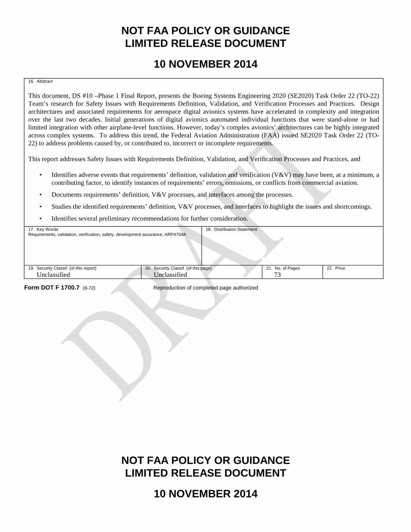
16. Abstract This document, DS #10 –Phase 1 Final Report, presents the Boeing Systems Engineering 2020 (SE2020) Task Order 22 (TO-22) Team’s research for Safety Issues with Requirements Definition, Validation, and Verification Processes and Practices. Design architectures and associated requirements for aerospace digital avionics systems have accelerated in complexity and integration over the last two decades. Initial generations of digital avionics automated individual functions that were stand-alone or had limited integration with other airplane-level functions. However, today’s complex avionics’ architectures can be highly integrated across complex systems. To address this trend, the Federal Aviation Administration (FAA) issued SE2020 Task Order 22 (TO-22) to address problems caused by, or contributed to, incorrect or incomplete requirements. This report addresses Safety Issues with Requirements Definition, Validation, and Verification Processes and Practices, and
• Identifies adverse events that requirements’ definition, validation and verification (V&V) may have been, at a minimum, a contributing factor, to identify instances of requirements’ errors, omissions, or conflicts from commercial aviation.
• Documents requirements’ definition, V&V processes, and interfaces among the processes.
• Studies the identified requirements’ definition, V&V processes, and interfaces to highlight the issues and shortcomings.
• Identifies several preliminary recommendations for further consideration. 17. Key Words Requirements, validation, verification, safety, development assurance, ARP4754A
18. Distribution Statement
19. Security Classif. (of this report) Unclassified
20. Security Classif. (of this page) Unclassified
21. No. of Pages 73
22. Price
Form DOT F 1700.7 (8-72) Reproduction of completed page authorized

NOT FAA POLICY OR GUIDANCE LIMITED RELEASE DOCUMENT
10 NOVEMBER 2014
i NOT FAA POLICY OR GUIDANCE LIMITED RELEASE DOCUMENT
10 NOVEMBER 2014
ACKNOWLEDGEMENTS
The Boeing TO-22 Team would like to acknowledge the use of content from the Australian Transportation Safety Board in regards to Transport Safety Investigation Report, Aviation Occurrence Report - 200503722 for the 2005 Malaysian Airlines 777 in-flight upset event (ref. quoted sentence in sections 4.1.1.1 and 4.3.1.5 of this report). This report identifies that the following notice should also be included:
“Published by: Australian Transport Safety Bureau Postal address: PO Box 967, Civic Square ACT 2608 Office location: 15 Mort Street, Canberra City, Australian Capital Territory Telephone: 1800 621 372; from overseas + 61 2 6274 6590
Accident and serious incident notification: 1800 011 034 (24 hours) Facsimile: 02 6274 6474; from overseas + 61 2 6274 6474 E-mail: [email protected] Internet: www.atsb.gov.au © Commonwealth of Australia 2007. This work is copyright. In the interests of enhancing the value of the information contained in this publication you may copy, download, display, print, reproduce and distribute this material in unaltered form (retaining this notice). However, copyright in the material obtained from non- Commonwealth agencies, private individuals or organisations, belongs to those agencies, individuals or organisations. Where you want to use their material you will need to contact them directly. Subject to the provisions of the Copyright Act 1968, you must not make any other use of the material in this publication unless you have the permission of the Australian Transport Safety Bureau. Please direct requests for further information or authorisation to:
Commonwealth Copyright Administration, Copyright Law Branch Attorney-General’s Department, Robert Garran Offices, National Circuit, Barton ACT 2600 www.ag.gov.au/cca”
NOT FAA POLICY OR GUIDANCE LIMITED RELEASE DOCUMENT
10 NOVEMBER 2014
ii NOT FAA POLICY OR GUIDANCE LIMITED RELEASE DOCUMENT
10 NOVEMBER 2014
TABLE OF CONTENTS
Page EXECUTIVE SUMMARY vii 1. INTRODUCTION. 1
2. BACKGROUND. 4
3. DIGITAL ELECTRONICS AND COMMUNICATION. 4
4. RESEARCH APPROACH, FINDINGS AND RECOMMENDATIONS. 10
4.1 White Paper 1. 10 4.1.1 Research Approach. 11 4.1.2 Findings. 14 4.1.3 Recommendation. 17
4.2 White Paper 2. 18 4.2.1 Research Approach. 18 4.2.2 Preliminary Findings. 19 4.2.3 Preliminary Recommendations. 10
4.3 White Paper 3. 11 4.3.1 Research Approach. 11 4.3.2 Preliminary Findings. 14 4.3.3 Preliminary Recommendations. 26
5. SUMMARY OF WHITE PAPERS, PHASE 1 PRELIMINARY FINDINGS, AND
RECOMMENDATIONS FOR CONTINUATION OF PHASES 2 AND 3. 26
5.1 Summary of Phase 1 Preliminary Findings 27 5.2 Summary of Preliminary Recommendations 27
6. REFERENCES. 29
APPENDICES APPENDIX A— TO-22 STATEMENT OF WORK TASK DESCRIPTIONS FOR
WHITE PAPERS 1, 2, AND 3 (DS #4, 5, AND 6)A-ERROR! BOOKMARK NOT DEFINED.
NOT FAA POLICY OR GUIDANCE LIMITED RELEASE DOCUMENT
10 NOVEMBER 2014
iii NOT FAA POLICY OR GUIDANCE LIMITED RELEASE DOCUMENT
10 NOVEMBER 2014
APPENDIX B— WHITE PAPER 1 EVENTS NOT SELECTED FOR FURTHER RESEARCH B-ERROR! BOOKMARK NOT DEFINED.
APPENDIX C— NEXT GENERATION AIR TRANSPORTATION SYSTEM (NEXTGEN) DISCUSSION C-ERROR! BOOKMARK NOT DEFINED.
APPENDIX D— PROJECT DELIVERABLES D-ERROR! BOOKMARK NOT DEFINED.

NOT FAA POLICY OR GUIDANCE LIMITED RELEASE DOCUMENT
10 NOVEMBER 2014
iv NOT FAA POLICY OR GUIDANCE LIMITED RELEASE DOCUMENT
10 NOVEMBER 2014
LIST OF FIGURES Figure Page 1. Civil Airborne Software Development (Software Lines of Code by Decade) 7 2. Down-Select Method 13 3. Air Worthiness Directives for Additional Analysis 17 4. Interrelationships Between Processes 22 5. Relationship of Advisory Circulars 25 6. Typical OEM Versus Supplier Roles and Responsibilities 26 7. Requirements Decomposition/Derivation Required for Allocation 29 8. FAA Training on ARP4754A Relationship to DO-178/254 [16] 1 9. Systems Engineering “V” Model 2 10. Safety V Model 3 11. Systems Engineering V Model’s Missing Middle 4 12. Federated Versus Integrated, Distributed Systems 5 13. Unacceptable, Cumulative Cascading Failure Effects 7 14. More Federated System 8 15. More Integrated System 8 16. Abstraction/Mental Model to Software 21 17. Integrated Systems 22 18. Vertical Integration of Requirements 23

NOT FAA POLICY OR GUIDANCE LIMITED RELEASE DOCUMENT
10 NOVEMBER 2014
v NOT FAA POLICY OR GUIDANCE LIMITED RELEASE DOCUMENT
10 NOVEMBER 2014
LIST OF TABLES
Table Page 1. Initial Data Sources 11 2. Potential Candidates 14 3. Existing Industry Processes 19 4. Industry Guidance Acceptability for Integral Processes 5

NOT FAA POLICY OR GUIDANCE LIMITED RELEASE DOCUMENT
10 NOVEMBER 2014
vi NOT FAA POLICY OR GUIDANCE LIMITED RELEASE DOCUMENT
10 NOVEMBER 2014
LIST OF ABBREVIATIONS AND ACRONYMS
A/C Aircraft AC Advisory Circular AD Airworthiness Directive ADIRU Air Data Inertial Reference Unit AEH Airborne Electronic Hardware AIR Aerospace Information Report ARP Aerospace Recommended Practice ATC Air Traffic Control ATSB Australian Transport Safety Bureau BCA Boeing Commercial Airplanes BQN Borinquen International Airport CA California CAGE Commercial and Government Entity CAS Caution Advisory System CDU Control Display Unit CIA Change Impact Analysis DC District of Columbia DO Document Order DS Delivery Schedule ECL Electronic Checklist FAA Federal Aviation Administration FHA Functional Hazard Assessment GPS Global Positioning System IMA Integrated Modular Avionics LPT Low Pressure Turbine LRU Line Replaceable Unit MD McDonnell Douglas MIT Massachusetts Institute of Technology MS Microsoft NASA National Aeronautics and Space Administration NEXTGEN Next Generation Air Transportation System OEM Original Equipment Manufacturer PSSA Preliminary System Safety Assessment PVR Puerto Vallarta PWS Performance Work Statement SAE Society of Automotive Engineers

NOT FAA POLICY OR GUIDANCE LIMITED RELEASE DOCUMENT
10 NOVEMBER 2014
vii NOT FAA POLICY OR GUIDANCE LIMITED RELEASE DOCUMENT
10 NOVEMBER 2014
SE2020 Systems Engineering 2020 SME Subject Matter Expert SOW Statement of Work SR Swissair SW Software TO Task Order TO-22 Task Order 22 TSB Transportation Safety Board UTC Universal Coordinated Time V&V Validation and Verification

NOT FAA POLICY OR GUIDANCE LIMITED RELEASE DOCUMENT
10 NOVEMBER 2014
viii NOT FAA POLICY OR GUIDANCE LIMITED RELEASE DOCUMENT
10 NOVEMBER 2014
EXECUTIVE SUMMARY
Design architectures and associated requirements for aerospace digital avionics systems have experienced acceleration in complexity and integration over the last two decades. Where initial generations of digital avionics automated individual functions that were often stand-alone or limited in integration with other airplane-level functions, today’s complex avionics’ architectures can be highly integrated across complex systems. To address this trend, the Federal Aviation Administration (FAA) issued SE-2020 Task Order (TO-22) to address problems caused by, or contributed to, incorrect or incomplete requirements. The TO-22 Statement of Work focuses on requirements definition, validation and verification. The objective of Boeing’s research is to focus where the current requirements development, validation and verification processes are breaking down, identify why problems continue to occur for aircraft with digital systems requirements, and determine approaches that will mitigate such occurrences. To meet the requirements of this task order, the Boeing TO-22 Team conducted research and formulated preliminary recommendations to: • Identify adverse events that requirements’ definition and validation and verification
(V&V) may have been, at a minimum, a contributing factor, as necessary to identify instances of requirements’ errors, omissions, or conflicts from commercial aviation (originally submitted in DS #4, White Paper 1).
• Identify and document requirements’ definition, V&V processes, and interfaces among the processes (originally submitted in DS #5, White Paper 2).
• Study the identified requirements’ definition, V&V processes, and interfaces to highlight the issues and shortcomings (originally submitted in DS #6, White Paper 3).
The Boeing TO-22 Team’s approach to this work was to review events and scenarios where requirements problems may have been a contributing factor. We also reviewed industry guidance for possible gaps for requirements formulation and V&V for complex avionics’ architectures. Based on this research, the Boeing TO-22 Team identified several findings and a

NOT FAA POLICY OR GUIDANCE LIMITED RELEASE DOCUMENT
10 NOVEMBER 2014
ix NOT FAA POLICY OR GUIDANCE LIMITED RELEASE DOCUMENT
10 NOVEMBER 2014
recommendation in White Paper 1, and preliminary findings and recommendations in White Papers 2 and 3. Included were identification of adverse events, evaluation of industry requirements’ definition and V&V processes used by OEMs and suppliers, and identification of several issues and shortcomings, particularly with integration of these processes with complex systems.

NOT FAA POLICY OR GUIDANCE LIMITED RELEASE DOCUMENT
10 NOVEMBER 2014
1 NOT FAA POLICY OR GUIDANCE LIMITED RELEASE DOCUMENT
10 NOVEMBER 2014
1. INTRODUCTION.
The FAA awarded Task Order 22 (TO-22) to Boeing on September 20, 2013 with a period of performance of October 1, 2013 to April 29, 2016 (if options one and two are exercised). TO-22 includes three phases [1]: • Base Phase 1 – October 1, 2013 through October 30, 2014 • Optional Phase 2 –October 31, 2014 through October 30, 2015 • Optional Phase 3 – October 31, 2015 through April 30, 2016 The FAA will determine the awarding of Optional Phases 2 and 3 based on research results from the prior phase. Phase 1 deliverables included three white papers that served as the basis for this report: • Delivery Schedule (DS) #4 – White Paper 1 (submitted February 28, 2014).
Identification of adverse events that requirements’ definition and validation and verification (V&V) may have been, at a minimum, a contributing factor, as necessary to identify instances of requirements’ errors, omissions, or conflicts from commercial aviation.
• DS #5 – White Paper 2 (submitted April 30, 2014). Identification and documentation of requirements’ definition, V&V processes, and interfaces among processes.
• DS #6 – White Paper 3 (submitted June 30, 2014). Identification of requirements’ definition and V&V processes, and interfaces to identify the issues and shortcomings.
To conduct the research for Phase 1, the Boeing TO-22 Team employed a systems engineering approach to identify adverse events and scenarios, and to identify requirements definition and V&V process issues and shortcomings. The Boeing TO-22 Team evaluated selected sources of information based on recommended resources listed in TO-22. The principal sources chosen were: • Review of Boeing Commercial Airplanes (BCA) in-service data fleet service bulletins
NOT FAA POLICY OR GUIDANCE LIMITED RELEASE DOCUMENT
10 NOVEMBER 2014
2 NOT FAA POLICY OR GUIDANCE LIMITED RELEASE DOCUMENT
10 NOVEMBER 2014
• Review of BCA product development flight squawks
• Review of FAA airworthiness directives
• Internal airplane safety events and information databases
• Safety lessons learned
• Discussions/meetings with BCA safety and requirements subject matter experts
• SAE S-18 committee participation, providing a valuable conduit for direct communication with industry and understanding the direction of these guidelines
To address potential process issues and shortcomings, the Boeing TO-22 Team reviewed the following industry process documents: • SAE ARP4754A/EUROCAE ED-79A, “Guidelines for Development of Civil Aircraft
and Systems,” December 21, 2010, covering development assurance processes [2]
• SAE ARP4754/EUROCAE ED-79, “Certification Considerations for Highly Integrated or Complex Aircraft Systems,” 1996, likewise covering development assurance processes [3]
• SAE ARP 4761, “Guidelines and Methods for Conducting the Safety Assessment Process on Civil Airborne Systems,” 1996, describing safety assessment processes [7]
• DO-178B/C, “Software Considerations in Airborne Systems and Equipment Certification,” RTCA Inc., Washington, DC, 2001, covering software design assurance processes [9]
• DO-254, “Design Assurance Guidance for Airborne Electronic Hardware,” RTCA Inc., Washington, DC, April 19, 2000, covering airborne electronic hardware design assurance processes [10]
The principal results of the Phase 1 research are to (1) clarify roles and responsibilities between OEMs and suppliers, (2) work to a complete and correct set of requirements, (3) potentially
NOT FAA POLICY OR GUIDANCE LIMITED RELEASE DOCUMENT
10 NOVEMBER 2014
3 NOT FAA POLICY OR GUIDANCE LIMITED RELEASE DOCUMENT
10 NOVEMBER 2014
identify and address process gaps in industry V&V guidance material, and (4) to improve the integration of V&V processes.

NOT FAA POLICY OR GUIDANCE LIMITED RELEASE DOCUMENT
10 NOVEMBER 2014
4 NOT FAA POLICY OR GUIDANCE LIMITED RELEASE DOCUMENT
10 NOVEMBER 2014
2. BACKGROUND.
During the last two decades, the complexity and integration of design architectures and associated requirements for aerospace digital avionics systems have increased. While initial generations of digital avionics automated individual functions that were often stand-alone or limited in integration with other functions, today’s complex avionics’ architectures are highly integrated across complex systems. Furthermore, emerging next generation air traffic management systems are further integrating platform-level complex systems into a broader system of systems, where data is shared across aircraft and air traffic management resources without pilot/controller intervention. Integrating complex systems has resulted in increased systems interdependence and integration. Compelling questions before both industry and regulators alike are • What are commonly accepted industry guidelines and practices used in requirements
capture, definition and V&V processes?
• What does the trend of accelerated growth of systems’ complexity mean to our design and V&V practices?
• What changes are required in our approaches to address this trend?
Realization of this trend was one of the key drivers for the creation of the new Aerospace Recommended Practice 4754 Revision A (ARP4754 Rev A [2]). ARP4754 Rev New (and later Rev A) was originally developed in response to a request from the FAA to the Society of Automotive Engineers (SAE) to define an acceptable development assurance process for highly integrated and complex avionics systems [3]. The issuance of ARP4754 Rev A provides industry with guidance toward a framework that addresses the growth of increased integration and complexity. In addition, the industry and regulators are potentially considering further steps. 3. DIGITAL ELECTRONICS AND COMMUNICATION.
Minimizing developmental errors and ensuring integration of highly integrated, safety critical systems has become more challenging on several fronts—namely due to increasing system

NOT FAA POLICY OR GUIDANCE LIMITED RELEASE DOCUMENT
10 NOVEMBER 2014
5 NOT FAA POLICY OR GUIDANCE LIMITED RELEASE DOCUMENT
10 NOVEMBER 2014
integration and increasing data management complexity. There is generally universal recognition that systems are becoming more complex. In addition, integrating these complex systems with other complex systems results in increased interdependence and integration. As airplane systems have become more complex and interdependent, the challenge of building well-behaved systems becomes more difficult. Throughout most industries, systems architectures have evolved to combine functionality from previous physically separate systems into integrated, software intensive systems. Examining the evolution of communications technologies provides informative comparisons to the evolution of complex digital aviation systems. Early versions of telegraph systems provided a seminal link to long distance communications over wire. Early wireless systems provided the ability to communicate by one-way transmitters/receivers (radios) and two-way transceivers. These systems evolved and later supported voice communications (telephone) and video communications (television). Early cellular phones provided a mobile telephone to those who could afford their cost. However, each of these technologies remained separate and were not integrated. Fast-forward 25 years, and we have a single digital device that combines all of these capabilities and more into a single smart phone that provides voice and text communications, on-screen video playback and recording, Global Positioning System (GPS) location, and access to the Internet, all at a price that falls well below that of early cell phones. There has been a trend across most industries to combine functionality from previously separate physical systems into integrated systems. While this is certainly the case with the aviation industry, systems architecture evolution may not be as immediately obvious to the flying public. The Boeing 767 and 787 both serve the same middle market; both aircraft have a similar external appearance. However, the difference between their digital avionics architecture is as significant as the difference between early cell phones and today’s smart phones. With the issuance of ARP4754A, regulators have taken a first step in addressing requirements identification and V&V processes that were formulated for federated systems. Yet, the question of whether more is needed to ensure equivalent safety of complex integrated system architectures has arisen. The fundamental course of study for TO-22 will address this question by seeking to identify potential gaps in the current requirements formulation and V&V process. To highlight the implications of architecture changes on the requirements process, aircraft such as the piston-engine Boeing 377 had systems that were functionally and physically separate. The

NOT FAA POLICY OR GUIDANCE LIMITED RELEASE DOCUMENT
10 NOVEMBER 2014
6 NOT FAA POLICY OR GUIDANCE LIMITED RELEASE DOCUMENT
10 NOVEMBER 2014
1949 flight deck of a Boeing 377 Stratocruiser represents a federated architecture. It was relatively easy for a single designer to define the interfaces. The integration effort was correspondingly simple. There were very limited cross-functional cascading effects, making failure behavior easier to understand. From an individual designer’s perspective, it was relatively easy to design, validate, integrate, and test. However, there were also some disadvantages to this design. It required significant effort for the crew to process the information displayed while maintaining situational awareness. The workload was so great that a third person was required to perform the navigation function so the pilots could focus on basic flight activities. Modern aircraft like the Boeing 787 that employ complex digital systems enjoy increased functionality, performance, and integration. The 787 Dreamliner is an example of the latest flight deck evolution. It has incorporated an integrated modular avionics (IMA) architecture and a distributed electrical power system architecture. Moving to IMA architecture and introducing more electrically powered systems helped improve performance and reduced overall airplane weight, but these design decisions also increased the importance of managing system interfaces. For the IMA architecture, airplane functions traditionally supported in a federated manner were now integrated on a common platform. The electrical system moved from a traditional centralized bus design to a remote distribution design. There are numerous advantages to this type of architecture, primarily in the increased functionality and performance of the aircraft. In this flight deck, it is much easier for the crew to maintain situational awareness. Examples of some of the integrated systems that enable improved situational awareness and help create an easy-to-manage flight deck include: • Weather radar • Terrain collision avoidance • Thrust management system • Flight management system • Heads-up displays However, this integrated architecture drives a corresponding increase in complexity and in cross-functional allocation. Interfaces tend to be defined by many inputs and outputs, resulting in increased integration efforts. Failure behavior can be more opaque, so the effort to understand cascading effects becomes very important. As shown in figure 1, airplanes with highly integrated modular avionics architectures have measureable increases in complexity and integration, as is

NOT FAA POLICY OR GUIDANCE LIMITED RELEASE DOCUMENT
10 NOVEMBER 2014
7 NOT FAA POLICY OR GUIDANCE LIMITED RELEASE DOCUMENT
10 NOVEMBER 2014
apparent by the number of interfaces or software lines of code (this data is for illustrative purposes only and does not represent an actual aircraft).
Figure 1. Civil Airborne Software Development (Software Lines of Code by Decade)
The requirements process for functionally and physically separated systems of federated airplanes may no longer apply to complex integrated airplanes. As systems architectures have evolved to become more complex, integrated, and distributed, an increased focus on requirements development and V&V processes is suggested. V&V efforts become even more important due to the systems architecture evolution from federated to integrated, distributed architectures. The increased integration, data traffic, and network intricacy associated with integrated, distributed systems does have costs related to complications in understanding the operational availability of system services and data flows. System behavior, particularly during system disturbances and failures, for federated architectures may be transparent and easily understood, but system behavior may not be as apparent for complex, integrated systems. In a federated architecture, the failure of a component may result in isolated effects that rarely touch more than one or two systems. With highly integrated architectures, the failure of a single component can propagate to numerous systems and result in diverse failure effects. This increases the challenges of designing well-integrated systems and fully validating that safety is maintained throughout the operational environment.

NOT FAA POLICY OR GUIDANCE LIMITED RELEASE DOCUMENT
10 NOVEMBER 2014
8 NOT FAA POLICY OR GUIDANCE LIMITED RELEASE DOCUMENT
10 NOVEMBER 2014
A key part of understanding the requirements process for complex integrated airplanes is to evaluate cross-functional interfaces and cascading failure effects. A failure in one system could result in some very undesirable effects in another system, which can lead to some very undesirable effects in its redundant systems. As aircraft architectures have evolved to integrated modular avionics, many airplane functions that had been historically supported with federated (i.e., non-integrated) systems are now interrelated and highly integrated. Therefore, many system functions, which typically had been separated with limited interdependence, now are very interrelated and highly integrated. The possibility exists that certain failure modes, which in a federated system may have had limited effect on other systems, may now have a cascading effect on other systems. There is a need to validate that failures do not have unintended, unacceptable cascading effects. In addition to understanding the cascading effects and ensuring that an acceptable level of safety is maintained during degraded performance, we must also consider how information is presented to the flight crew, to ensure that they can take appropriate actions. The FAA has noted that “(i)n previous certifications of aircraft with IMA architecture, and some with remotely distributed electrical architecture, unique IMA or electrical system distribution failures have manifested which presented rather new and unique failure presentations and problems to aircrews. Specifically, instances of • Partial or complete failure of an IMA system causing significant cascading failure effects
on numerous aircraft functions. The result was numerous, confusing and at times unrelated Caution Advisory System (CAS) messages, quite often in no certain order with no indication as to the root cause of the problem. Recognizing and dealing with these multiple failure indications and CAS messages require extra crew training (e.g., pattern recognition), knowledge, and workload. In some cases, electronic checklists could not effectively handle the actual failure situation. The aircrew had to resort to manual paper checklist procedures specifically developed to troubleshoot the failure using a fault-tree methodology for determining the root cause and how to deal with it.
• Critical cascading failure indications (i.e., cabin pressurization) requiring relatively prompt crew attention. Sometimes such critical failure indications were buried among other failure indications.
• Loss of all displays due to an anomalous IMA process.
NOT FAA POLICY OR GUIDANCE LIMITED RELEASE DOCUMENT
10 NOVEMBER 2014
9 NOT FAA POLICY OR GUIDANCE LIMITED RELEASE DOCUMENT
10 NOVEMBER 2014
• Partial failure on two IMA systems (one channel of each unit) causing all primary flight deck displays to revert to a non-functional display presentation, forcing pilots to go to the standby flight displays.
• Uncommanded and inappropriate display reversions.
• Instances of simple failures (generator or engine loss) having a significant failure effect—disruption of power to a portion of the IMA architecture, and loss of all displays on one side of the cockpit.
• Complete loss of CAS capability under certain failure scenarios.
• Complete loss of Electronic Checklist (ECL) capability under certain failure scenarios.
• Electronic checklist not robust enough to deal with certain complex, multiple-system cascading failure scenarios.
• Generation of unnecessary checklists in the ECL system during cascading failure scenarios, adding to crew workload. Often, each unnecessary ECL had to be either individually worked or individually overridden.
• Degraded braking performance during landing or a rejected takeoff because of how inertial deceleration data was handled in the IMA or by the IMA during certain failure scenarios.
• Failure of single elements of the electrical distribution architecture causing wholesale loss of sensor or system information and the removal of such information from the cockpit systems synoptic. In some cases, certain aircraft systems may continue to operate, but any information on the health and performance of such systems was unavailable to the aircrew. Also, in some cases, secondary systems (i.e., aircraft pressurization) were negatively affected requiring the aircrew to take precautionary measures (i.e., descent to a safe altitude for pressurization) because of uncertainties over system functionality and performance.” [4]
Restated, the essence of TO-22 is to identify where requirements definition V&V processes fail, why problems occur, and approaches to mitigate the problem occurrences.
NOT FAA POLICY OR GUIDANCE LIMITED RELEASE DOCUMENT
10 NOVEMBER 2014
10 NOT FAA POLICY OR GUIDANCE LIMITED RELEASE DOCUMENT
10 NOVEMBER 2014
4. RESEARCH APPROACH, FINDINGS AND RECOMMENDATIONS.
The Performance Work Statement (PWS) for TO-22 states: “Phase 1 requires the contractor to identify possible issues and shortcomings with the current process used by the commercial aviation industry regarding requirements’ definition, validation, and verification for aircraft digital system requirements. Processes that must be considered include, but are not limited to: • Processes used for initial identification and documentation of system level requirements,
including inter-system behavior and desired operation during failure conditions. This is referred to as “definition of requirements” in this task.
• Processes used to ensure that system-level requirements are correct. This is included in the term “validation of requirements” in this task.
• Processes used to ensure that system-level requirements are complete. This is included in the term “validation of requirements” in this task.
• Processes used to ensure that definition of requirements is consistent across multiple systems, for normal operation and for failure conditions, and that the multiple systems do not work at cross-purposes to each other. This is included in the term “validation of requirements” in this task.
• Processes used to ensure that the aircraft systems, both individually and collectively, operate per the defined requirements. This is referred to as “verification of requirements” in this task” [1].
For reference, the TO-22 PWS task descriptions for White Papers 1, 2, and 3 (DS #6, 7, and 8) are provided in appendix A of this document. 4.1 WHITE PAPER 1.
White Paper 1 was the first of three white papers that addressed the TO-22 Phase 1 PWS “Identify adverse events for which requirement definition, V&V may have been, at a minimum, a contributing factor” [1]. The following subsections address the research approach, findings, and recommendations.

NOT FAA POLICY OR GUIDANCE LIMITED RELEASE DOCUMENT
10 NOVEMBER 2014
11 NOT FAA POLICY OR GUIDANCE LIMITED RELEASE DOCUMENT
10 NOVEMBER 2014
4.1.1 Research Approach.
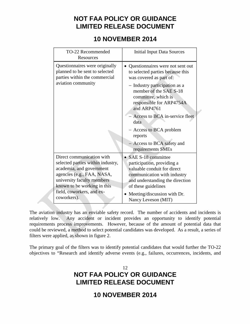
The Boeing TO-22 Team researched internal and external database sources to identify adverse events for which requirements definition and V&V may have been, at a minimum, a contributing factor. Table 1 identifies the initial input data sources that were used. The most productive sources were the discussions with BCA safety and requirements subject matter experts.
Table 1. Initial Data Sources
TO-22 Recommended Resources
Initial Input Data Sources
Personal knowledge and direct experience of contractor
• Review of BCA in-service data fleet advisory directives, service bulletins, and flight squawks
• Internal airplane safety events and information databases
• Safety lessons learned • Discussions/meetings with BCA
safety and requirements subject matter experts
Literature search • Flight Safety Foundation • Aviation Safety Network • Skybrary • Engineering A Safer World:
Systems Thinking Applied to Safety, Nancy Leveson
Investigation of publicly available official reports involving commercial aviation accidents and safety-related incidents
• NTSB • FAA Lessons Learned • TSB Canada • Australian Transport Safety
Bureau • Airworthiness Directives
NOT FAA POLICY OR GUIDANCE LIMITED RELEASE DOCUMENT
10 NOVEMBER 2014
12 NOT FAA POLICY OR GUIDANCE LIMITED RELEASE DOCUMENT
10 NOVEMBER 2014
TO-22 Recommended Resources
Initial Input Data Sources
Questionnaires were originally planned to be sent to selected parties within the commercial aviation community
• Questionnaires were not sent out to selected parties because this was covered as part of: − Industry participation as a
member of the SAE S-18 committee, which is responsible for ARP4754A and ARP4761
− Access to BCA in-service fleet data
− Access to BCA problem reports
− Access to BCA safety and requirements SMEs
Direct communication with selected parties within industry, academia, and government agencies (e.g., FAA, NASA, university faculty members known to be working in this field, coworkers, and ex-coworkers).
• SAE S-18 committee participation, providing a valuable conduit for direct communication with industry and understanding the direction of these guidelines
• Meeting/discussion with Dr. Nancy Leveson (MIT)
The aviation industry has an enviable safety record. The number of accidents and incidents is relatively low. Any accident or incident provides an opportunity to identify potential requirements process improvements. However, because of the amount of potential data that could be reviewed, a method to select potential candidates was developed. As a result, a series of filters were applied, as shown in figure 2. The primary goal of the filters was to identify potential candidates that would further the TO-22 objectives to “Research and identify adverse events (e.g., failures, occurrences, incidents, and

NOT FAA POLICY OR GUIDANCE LIMITED RELEASE DOCUMENT
10 NOVEMBER 2014
13 NOT FAA POLICY OR GUIDANCE LIMITED RELEASE DOCUMENT
10 NOVEMBER 2014
accidents) for which requirements definition and V&V may have been, at a minimum, a contributing factor” [1]. In addition, the filtering criteria were consistent with the guidance provided in TO-22: • This research was limited to those aspects related to the specification of digital systems—
that is, those systems that involve microprocessors, software, digital networks, and other such digitally based system elements.
• It did not investigate issues involving structural, mechanical, hydraulic, pneumatic, or electrical power systems, unless those systems also involved control and monitoring by digital systems.
• The FAA recommended that the Contractor use a window of January 2000 to the present.
Figure 2. Down-Select Method

NOT FAA POLICY OR GUIDANCE LIMITED RELEASE DOCUMENT
10 NOVEMBER 2014
14 NOT FAA POLICY OR GUIDANCE LIMITED RELEASE DOCUMENT
10 NOVEMBER 2014
The primary data sources reviewed were the National Transportation Safety Board (NTSB) database, the FAA lessons-learned data, and the BCA safety databases. The first filter excluded utility, acrobatic, and commuter category airplanes. This was primarily done because of the potential difficulty in getting additional data. The next filter considered the time frame. While the TO-22 SOW recommended starting at year 2000; the research period was extended to Sept. 1998 to include the Swissair MD-11 event. The next filter eliminated cases that appeared to be mostly structurally related. Fatigue is important, but translating these insights to digital avionics systems would be difficult. The next filter considered if the accident/incident was associated with unintended effects for highly integrated systems. As part of this review, candidates were removed that appeared to be operational in nature (e.g., an aircraft landing at the wrong airport). The Task Order identifies the need to “include pilot evaluation of aircraft level operations” [1]. This is where having access to safety and requirements subject matter experts was helpful in identifying potential cases to review in further detail. Throughout this exercise, special attention was paid to how the information could be used from a requirements definition and V&V process. 4.1.2 Findings.
Prior to any literature review or searching of internal and external databases, one candidate immediately stood out as a great candidate. However, the decision was made not to immediately select the case. Each step in this process allowed an evaluation for general trends in requirements definition and V&V. One of the key reasons that the potential candidates, listed in table 2, were reviewed in further detail was to consider the “pilot evaluation of aircraft operation.” It is for this reason that accidents such as the Swissair in-flight fire were included. It was not directly related to digital avionics systems, but it was an opportunity to consider this from an operational and wiring requirements perspective.
Table 2. Potential Candidates
Date Airline A/C Model Location
1998-09-02 Swissair Flight SR 111
MD-11 Nova Scotia

NOT FAA POLICY OR GUIDANCE LIMITED RELEASE DOCUMENT
10 NOVEMBER 2014
15 NOT FAA POLICY OR GUIDANCE LIMITED RELEASE DOCUMENT
10 NOVEMBER 2014
2000-01-31 Alaska Airlines Flight 261
MD-83 Pacific Ocean near Anacapa Island, CA
2007-08-20 China Airlines Flight 120
737-800 Okinawa, Japan
2009-06-01 Air France 447 A330-200 Atlantic Ocean 2010-11-04 Qantas 32 A380-800 Singapore 2005-08-01 Malaysian Airlines
777 777-200 Perth, Australia
After evaluating each of these events for potential TO-22 applicability, all but the 2005 Malaysian Airlines 777 Incident were rejected for reasons listed in appendix B. The 2005 Malaysian Airlines 777 incident occurred on 1 August 2005, at 17:03 Western Standard Time, as a Boeing 777-200 operated by Malaysian Airline System experienced a pitch up about 30 min after takeoff from Perth, Australia, while climbing through 36,000 ft with autopilot on [5]. During the pitch up, the aircraft climbed to 41,000 ft and the indicated airspeed dropped from 270 knots to 158 knots. The stick shaker and the stall warning indicator activated during the event. The flight landed uneventfully back at Perth [5]. On 29 August 2005, the FAA issued emergency Airworthiness Directive (AD) 2005-18-51 [6] to install Air Data Inertial Reference Unit-03 (ADIRU-03) software, stating that faulty ADIRU data could cause anomalies in 777 primary flight controls, autopilot, pilot displays, autobrakes, and autothrottles. The Australian Transport Safety Bureau (ATSB), Transport Safety Investigation Report, Aviation Occurrence Report - 200503722 concluded that a contributing safety factor was “an anomaly existed in the component software hierarchy that allowed inputs from a known faulty accelerometer to be processed by the ADIRU and used by the primary flight computer, autopilot and other aircraft systems” [5]. The potential TO-22 applicability included: • Requirements definition and V&V (particularly related to fault handling requirements)

NOT FAA POLICY OR GUIDANCE LIMITED RELEASE DOCUMENT
10 NOVEMBER 2014
16 NOT FAA POLICY OR GUIDANCE LIMITED RELEASE DOCUMENT
10 NOVEMBER 2014
• Cascading system failure effects and crew workload
• This case was selected because it would allow an in-depth review, particularly from a requirements definition and V&V perspective, of the integration between the different industry standards listed below:
− ARP4761, “Guidelines and Methods for Conducting the Safety Assessment Process on Civil Airborne Systems” [7]
− ARP4754A, “Guidelines for Development of Civil Aircraft and Systems” [2]
− Document Order-297 (DO-297), “Integrated Modular Avionics (IMA) Development Guidance and Certification Considerations” [8]
− DO-178B/C, “Software Considerations in Airborne Systems and Equipment Certification” [9]
− DO-254, “Design Assurance Guidance for Airborne Electronic Hardware” [10]
The Boeing TO-22 Team also conducted a review of problem reports (from pre-flight systems architecture analyses and flight-test squawks) of recent product development programs. Specifically, Boeing looked at requirements changes, systems architecture changes, and software changes. To review possible linkages between ADs and TO-22, the Boeing TO-22 Team reviewed 46 ADs that addressed software involving Boeing aircraft. Three were selected for additional analysis, as shown in figure 3.

NOT FAA POLICY OR GUIDANCE LIMITED RELEASE DOCUMENT
10 NOVEMBER 2014
17 NOT FAA POLICY OR GUIDANCE LIMITED RELEASE DOCUMENT
10 NOVEMBER 2014
AD # AD Summary2005-18-51 This document publishes in the Federal Register an amendment adopting airworthiness directive (AD) 2005-18-51
that was sent previously to all known U.S. owners and operators of Boeing Model 777 airplanes by individual notices. This AD supersedes an existing AD that applies to certain Boeing Model 777-200 and ''300 series airplanes. The existing AD currently requires modification of the operational program software (OPS) of the air data inertial reference unit (ADIRU). This new AD requires installing a certain OPS in the ADIRU, and revising the airplane flight manual to provide the flightcrew with operating instructions for possible ADIRU heading errors and for potential incorrect display of drift angle. This AD results from a recent report of a significant nose-up pitch event. We are issuing this AD to prevent the OPS from using data from faulted (failed) sensors, which could result in anomalies of the fly-by-wire primary flight control, autopilot, auto-throttle, pilot display, and auto-brake systems. These anomalies could result in high pilot workload, deviation from the intended flight path, and possible loss of control of the airplane.
2014-06-04 We are adopting a new airworthiness directive (AD) for certain The Boeing Company Model 747-8 and 747-8F series airplanes powered by certain General Electric (GE) engines. This AD requires removing certain defective software and installing new, improved software. This AD was prompted by a determination that the existing electronic engine control (EEC) software logic can prevent stowage of the thrust reversers (TRs) during certain circumstances, which could cause the TRs to move back to the deployed position. We are issuing this AD to prevent in-flight deployment of one or more TRs due to loss of the TR auto restow function, which could result in inadequate climb performance at an altitude insufficient for recovery, and consequent uncontrolled flight into terrain.
2012-21-08 We are superseding an existing airworthiness directive (AD) for certain The Boeing Company Model 737-600, -700, -700C, -800, and -900 series airplanes. That AD currently requires installing and testing an updated version of the operational program software (OPS) of the flight control computers (FCCs). This new AD requires an inspection for part numbers of the operational program software of the flight control computers, and corrective actions if necessary. This AD was prompted by reports of undetected erroneous output from a single radio altimeter channel, which resulted in premature autothrottle retard during approach. We are issuing this AD to detect and correct an unsafe condition associated with erroneous output from a radio altimeter channel, which could result in premature autothrottle landing flare retard and the loss of automatic speed control, and consequent loss of control of the airplane.
Figure 3. Air Worthiness Directives for Additional Analysis
AD 2005-18-51 [6] stems from the Malaysian Airlines 777 pitch-up incident that occurred on 2 August 2005 as summarized above. AD 2014-06-04 [11] and AD 012-21-08 [12] were also considered for additional research but were later determined not to be required since additional scenarios for White Paper 3 were introduced to support the research. 4.1.3 Recommendation.
Based on the findings in section 4.1.2, Boeing recommended that the Malaysian Airline 777 pitch-up incident be utilized for further research in TO-22. To ensure an adequate quantity of cases were identified to complete the research, additional scenarios were evaluated as part of White Paper 3 (see scenario sections beginning with 4.3.2.3 and ending with 4.3.2.10 within this report for further information).

NOT FAA POLICY OR GUIDANCE LIMITED RELEASE DOCUMENT
10 NOVEMBER 2014
18 NOT FAA POLICY OR GUIDANCE LIMITED RELEASE DOCUMENT
10 NOVEMBER 2014
4.2 WHITE PAPER 2.
White Paper 2 was the second of three white papers that addressed the TO-22 Phase 1 PWS “Identify and document requirement definition, validation & verification processes, and interfaces among the processes” [1]. The following subsections address the research approach, preliminary findings, and preliminary recommendations. 4.2.1 Research Approach.
The following research approach was used for White Paper 2: • Identified existing industry guidelines for requirements definition and V&V processes
• Identified shortcomings in current processes in ARP4754A [2]
• Identified additional processes that are currently not part of ARP4754 [3]/ARP4754A [2] or industry best practices. This included:
− Identified existing industry guidelines for interfaces between:
o Airplane
o System/subsystem
o Software
o Airborne Electronic Hardware (AEH)
• Identified potential shortcomings in current process interfaces
• Identified additional process interface clarifications (particularly transition to and from ARP4754A [2] and DO-178 [9])
To identify potential shortcomings in industry guidelines, scenario(s) were considered in which following these industry guidelines perfectly could potentially fail to identify a potentially catastrophic condition.
NOT FAA POLICY OR GUIDANCE LIMITED RELEASE DOCUMENT
10 NOVEMBER 2014
19 NOT FAA POLICY OR GUIDANCE LIMITED RELEASE DOCUMENT
10 NOVEMBER 2014
Both nominal and failure modes were considered in the evaluation of potential requirements process deficiencies. Understanding the intrasystem and intersystem behavior and validating an acceptable level of safety is maintained in the presence of cascading failure effects was an integral part of this evaluation.
4.2.2 Preliminary Findings.
4.2.2.1 Overview of Existing Processes Related to Requirements Definition, Validation and Verification.
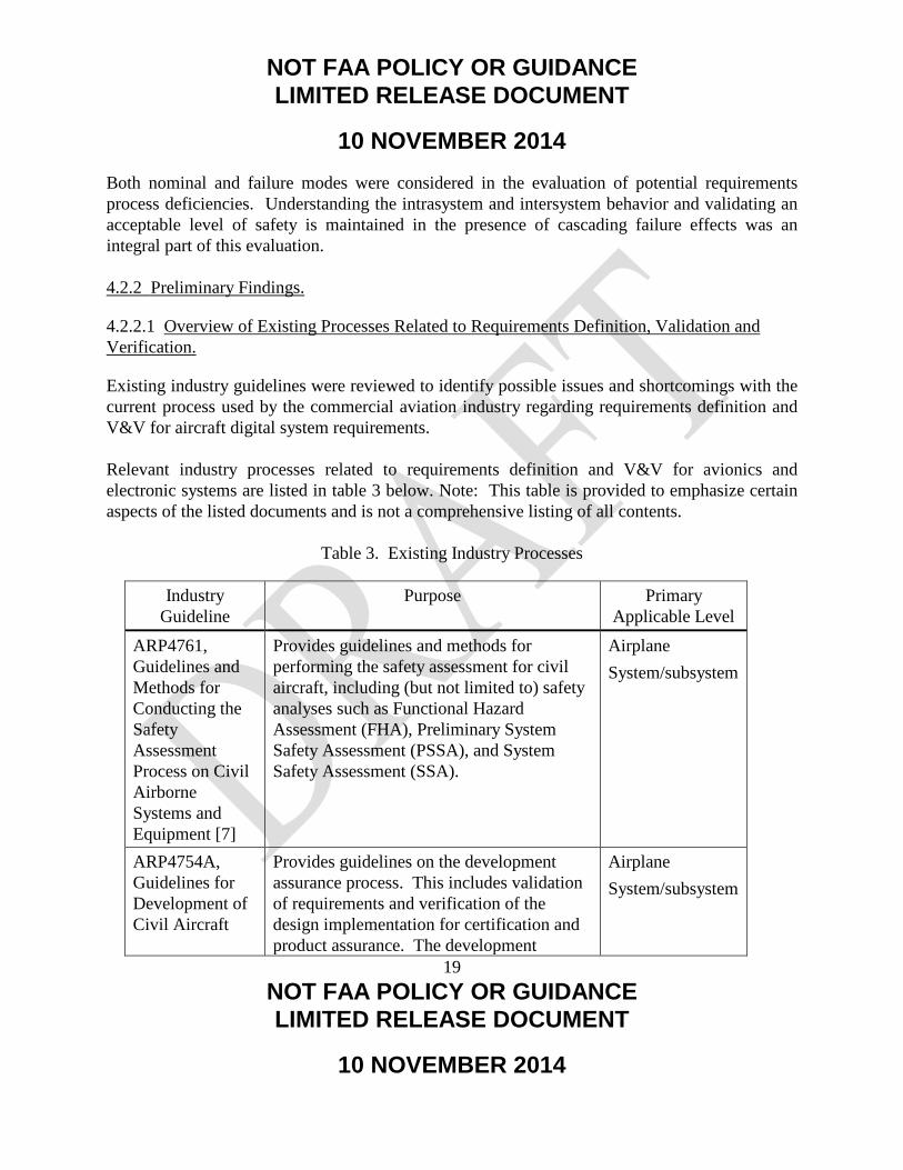
Existing industry guidelines were reviewed to identify possible issues and shortcomings with the current process used by the commercial aviation industry regarding requirements definition and V&V for aircraft digital system requirements. Relevant industry processes related to requirements definition and V&V for avionics and electronic systems are listed in table 3 below. Note: This table is provided to emphasize certain aspects of the listed documents and is not a comprehensive listing of all contents.
Table 3. Existing Industry Processes
Industry Guideline
Purpose Primary Applicable Level
ARP4761, Guidelines and Methods for Conducting the Safety Assessment Process on Civil Airborne Systems and Equipment [7]
Provides guidelines and methods for performing the safety assessment for civil aircraft, including (but not limited to) safety analyses such as Functional Hazard Assessment (FHA), Preliminary System Safety Assessment (PSSA), and System Safety Assessment (SSA).
Airplane System/subsystem
ARP4754A, Guidelines for Development of Civil Aircraft
Provides guidelines on the development assurance process. This includes validation of requirements and verification of the design implementation for certification and product assurance. The development
Airplane System/subsystem

NOT FAA POLICY OR GUIDANCE LIMITED RELEASE DOCUMENT
10 NOVEMBER 2014
20 NOT FAA POLICY OR GUIDANCE LIMITED RELEASE DOCUMENT
10 NOVEMBER 2014
Industry Guideline
Purpose Primary Applicable Level
and Systems [2] planning elements consist of: • Development • Safety Program • Requirements Management • Validation • Implementation Verification • Configuration Management • Process Assurance • Certification
DO-178C, Software Considerations in Airborne Systems and Equipment Certification [9]
Provides design assurance guidance for software of airborne systems and equipment. Key processes include:
• Software planning process • Software requirements process • Software design process • Software coding process • Software integration process • Software configuration management • Software quality assurance process • Certification liaison
Software
DO-254, Design Assurance Guidance for Airborne Electronic Hardware [10]
Provides design assurance guidance for the development of airborne electronic hardware. Key processes include:
• Hardware safety assessment • Requirements capture process • Validation • Verification
AEH
NOT FAA POLICY OR GUIDANCE LIMITED RELEASE DOCUMENT
10 NOVEMBER 2014
21 NOT FAA POLICY OR GUIDANCE LIMITED RELEASE DOCUMENT
10 NOVEMBER 2014
Industry Guideline
Purpose Primary Applicable Level
• Configuration management • Process assurance • Certification liaison
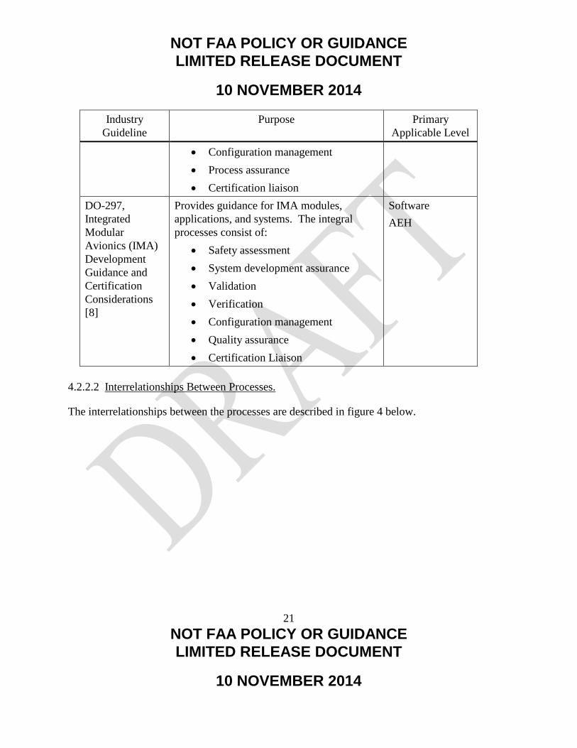
DO-297, Integrated Modular Avionics (IMA) Development Guidance and Certification Considerations [8]
Provides guidance for IMA modules, applications, and systems. The integral processes consist of:
• Safety assessment • System development assurance • Validation • Verification • Configuration management • Quality assurance • Certification Liaison
Software AEH
4.2.2.2 Interrelationships Between Processes.
The interrelationships between the processes are described in figure 4 below.

NOT FAA POLICY OR GUIDANCE LIMITED RELEASE DOCUMENT
10 NOVEMBER 2014
22 NOT FAA POLICY OR GUIDANCE LIMITED RELEASE DOCUMENT
10 NOVEMBER 2014
Figure 4. Interrelationships Between Processes
Figure 4 illustrates the flow between safety assessment processes covered by ARP4761 [7], development assurance processes covered by ARP4754 [3], and design assurance processes covered by DO-178 [9] and DO-254 [10]. For the purpose of this document, DO-178 and DO-254 will be referred to as “design assurance activities.” Function, failure, and safety information (particularly, derived safety requirements) flow from the ARP4761 processes to the ARP4754A processes. System design information flows from the ARP4754A processes to the ARP4761 processes. The transition from development assurance processes to software and hardware design assurance processes occurs when the requirements are allocated to hardware and software items. This is when the transition occurs from ARP4754/ARP4754A to DO-178 and DO-254. 4.2.2.3 Information Flow From System Development Assurance Processes and Software and AEH Design Assurance Processes.
Requirements are allocated to the following elements:
ARP4761
ARP4754
DO-297
DO-178 DO-254

NOT FAA POLICY OR GUIDANCE LIMITED RELEASE DOCUMENT
10 NOVEMBER 2014
23 NOT FAA POLICY OR GUIDANCE LIMITED RELEASE DOCUMENT
10 NOVEMBER 2014
• Hardware • Software • Development assurance level(s) and descriptions of Failure Condition(s), if applicable • Hardware allocated failure rates and exposure intervals • System description • Design constraints • System verification activities • Verification evidence ARP4754A [2] provides guidance in each of these areas. 4.2.2.4 Information Flow From Hardware/Software Processes to System Development Assurance Processes.
The hardware and software processes pass the following information to the system development assurance process: • Derived requirements • Hardware/software/system architecture description • Verification evidence • Failure rates and fault detection • Problem and change reports • Deficiencies or limitations of intended functionality • Installation drawings, schematics, part lists, etc. • System level verification plans
ARP4754A [2] provides guidance in each of these areas. 4.2.2.5 Information Flow Between Hardware and Software Processes.
The following information is passed between software and hardware processes: • Derived requirements • Hardware and software verification • Hardware and software incompatibilities ARP4754A [2] provides guidance in each of these areas.
NOT FAA POLICY OR GUIDANCE LIMITED RELEASE DOCUMENT
10 NOVEMBER 2014
24 NOT FAA POLICY OR GUIDANCE LIMITED RELEASE DOCUMENT
10 NOVEMBER 2014
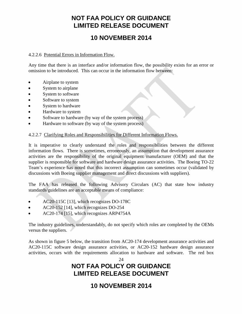
4.2.2.6 Potential Errors in Information Flow.
Any time that there is an interface and/or information flow, the possibility exists for an error or omission to be introduced. This can occur in the information flow between: • Airplane to system • System to airplane • System to software • Software to system • System to hardware • Hardware to system • Software to hardware (by way of the system process) • Hardware to software (by way of the system process)
4.2.2.7 Clarifying Roles and Responsibilities for Different Information Flows.
It is imperative to clearly understand the roles and responsibilities between the different information flows. There is sometimes, erroneously, an assumption that development assurance activities are the responsibility of the original equipment manufacturer (OEM) and that the supplier is responsible for software and hardware design assurance activities. The Boeing TO-22 Team’s experience has noted that this incorrect assumption can sometimes occur (validated by discussions with Boeing supplier management and direct discussions with suppliers). The FAA has released the following Advisory Circulars (AC) that state how industry standards/guidelines are an acceptable means of compliance: • AC20-115C [13], which recognizes DO-178C • AC20-152 [14], which recognizes DO-254 • AC20-174 [15], which recognizes ARP4754A
The industry guidelines, understandably, do not specify which roles are completed by the OEMs versus the suppliers. As shown in figure 5 below, the transition from AC20-174 development assurance activities and AC20-115C software design assurance activities, or AC20-152 hardware design assurance activities, occurs with the requirements allocation to hardware and software. The red box

NOT FAA POLICY OR GUIDANCE LIMITED RELEASE DOCUMENT
10 NOVEMBER 2014
25 NOT FAA POLICY OR GUIDANCE LIMITED RELEASE DOCUMENT
10 NOVEMBER 2014
indicates the focus area for the requirements allocation process. This step is key to ensuring that hardware and software design assurance activities start with a complete and correct set of requirements.
Figure 5. Relationship of Advisory Circulars
The importance of clarifying the OEM and suppliers’ roles and responsibilities was highlighted in discussions with different programs and suppliers. This becomes particularly true for business
NOT FAA POLICY OR GUIDANCE LIMITED RELEASE DOCUMENT
10 NOVEMBER 2014
26 NOT FAA POLICY OR GUIDANCE LIMITED RELEASE DOCUMENT
10 NOVEMBER 2014
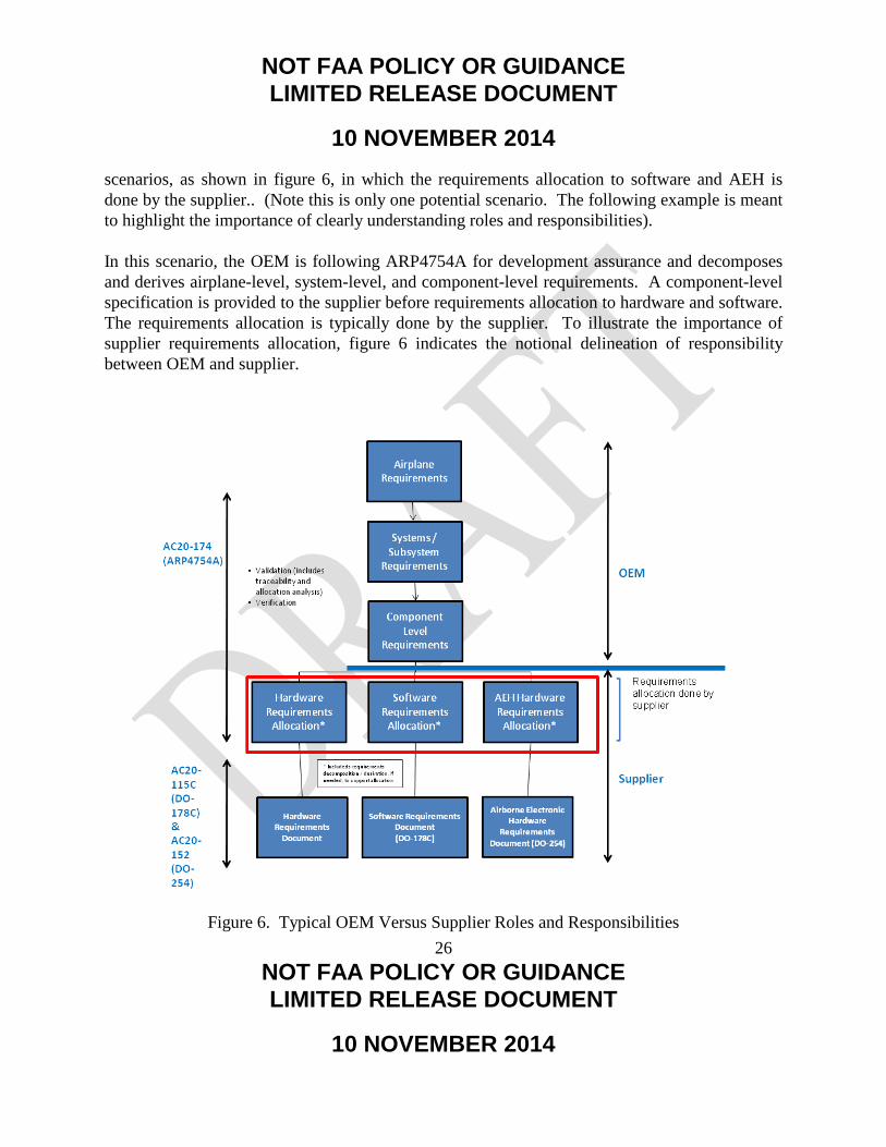
scenarios, as shown in figure 6, in which the requirements allocation to software and AEH is done by the supplier.. (Note this is only one potential scenario. The following example is meant to highlight the importance of clearly understanding roles and responsibilities). In this scenario, the OEM is following ARP4754A for development assurance and decomposes and derives airplane-level, system-level, and component-level requirements. A component-level specification is provided to the supplier before requirements allocation to hardware and software. The requirements allocation is typically done by the supplier. To illustrate the importance of supplier requirements allocation, figure 6 indicates the notional delineation of responsibility between OEM and supplier.
Figure 6. Typical OEM Versus Supplier Roles and Responsibilities

NOT FAA POLICY OR GUIDANCE LIMITED RELEASE DOCUMENT
10 NOVEMBER 2014
27 NOT FAA POLICY OR GUIDANCE LIMITED RELEASE DOCUMENT
10 NOVEMBER 2014
In figure 6 above, this means that the supplier would have some development assurance activities. Figure 7 shows this same concept from a slightly different perspective. If the requirements can be directly allocated to hardware and/or software (i.e., no further requirements’ decomposition or derivation is required to do the allocation), then the supplier can transition to DO-178 software design assurance processes or DO-254 hardware design assurance processes. If the supplier is required to conduct requirements decomposition or derivation before the requirements can be allocated to hardware and/or software, then the supplier has development assurance activity. In particular, the supplier would need to validate that the decomposed requirements have been validated to be complete and correct.

NOT FAA POLICY OR GUIDANCE LIMITED RELEASE DOCUMENT
10 NOVEMBER 2014
28 NOT FAA POLICY OR GUIDANCE LIMITED RELEASE DOCUMENT
10 NOVEMBER 2014

NOT FAA POLICY OR GUIDANCE LIMITED RELEASE DOCUMENT
10 NOVEMBER 2014
29 NOT FAA POLICY OR GUIDANCE LIMITED RELEASE DOCUMENT
10 NOVEMBER 2014
Figure 7. Requirements Decomposition/Derivation Required for Allocation
1 NOT FAA POLICY OR GUIDANCE LIMITED RELEASE DOCUMENT
10 NOVEMBER 2014
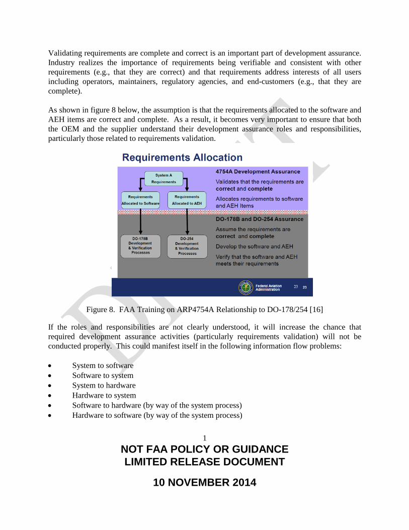
Validating requirements are complete and correct is an important part of development assurance. Industry realizes the importance of requirements being verifiable and consistent with other requirements (e.g., that they are correct) and that requirements address interests of all users including operators, maintainers, regulatory agencies, and end-customers (e.g., that they are complete). As shown in figure 8 below, the assumption is that the requirements allocated to the software and AEH items are correct and complete. As a result, it becomes very important to ensure that both the OEM and the supplier understand their development assurance roles and responsibilities, particularly those related to requirements validation.
Figure 8. FAA Training on ARP4754A Relationship to DO-178/254 [16]
If the roles and responsibilities are not clearly understood, it will increase the chance that required development assurance activities (particularly requirements validation) will not be conducted properly. This could manifest itself in the following information flow problems: • System to software • Software to system • System to hardware • Hardware to system • Software to hardware (by way of the system process) • Hardware to software (by way of the system process)

2 NOT FAA POLICY OR GUIDANCE LIMITED RELEASE DOCUMENT
10 NOVEMBER 2014
Based on the Boeing TO-22 Team’s experiences, this transition to and from ARP4754A [2] and DO-178 [9]/DO-254 [10] is an important clarification. Discussions with multiple organizations led to the conclusion that there is a certain amount of confusion regarding this topic. As shown in figure 8, the handoff between development assurance activities (covered by ARP4754A) and the design assurance activities (covered by DO-178 and DO-254) occurs after the requirements allocation to hardware and software. It is important to clearly establish the development assurance roles and responsibilities between the OEM and the suppliers. It should not always be assumed that a supplier has no development assurance activities. As a broad generalization, it appears that this incorrect assumption sometimes occurs because it is assumed that the contractual work statement is directly aligned to the transition between development assurance and design assurance (i.e., the OEM will be responsible for all ARP4754A type development assurance type activities, including requirements allocation to hardware and software). Boeing has found figures 5, 6, and 7 to be effective in clarifying the different roles and responsibilities. It should never be assumed that the OEM will be solely responsible for all development assurance activities and that the suppliers will only be responsible for DO-178 software design assurance processes and DO-254 hardware design assurance processes. 4.2.2.8 Classic Systems Engineering Validation and Verification
To a certain extent, the existing industry guidelines follow the classic systems engineering validation and verification model, shown in figure 9.
Figure 9. Systems Engineering “V” Model
Starting with ARP4754A on the left side of the V, aircraft functions and requirements are developed and derived. There is the further decomposition or derivation of requirements at

3 NOT FAA POLICY OR GUIDANCE LIMITED RELEASE DOCUMENT
10 NOVEMBER 2014
subsequently lower levels. From an ARP4754A perspective, a large part of the left side of the V is the validation of the requirements. The right side of the V involves the implementation verification of requirements at progressively higher levels. Similarly, ARP4761 follows a systems engineering V model as shown in figure 10.
Figure 10. Safety V Model
The left leg of the V represents a top-down requirement development and validation process. This includes the airplane FHA, the Preliminary Aircraft Safety Assessment, the System FHAs, the PSSA, and the preliminary (qualitative) Fault Tree Analyses. The inner V of figure 10 represents the common-cause analyses steps used to validate that no common threats or failure modes violate the redundancy designed into the systems. The right leg represents a bottom-up verification process. It includes the Failure Modes and Effects Analyses, Quantitative FTAs, SSAs, and Airplane Safety Assessment. In and of itself, there is nothing incorrect with the V model (as modeled in either ARP4754A or ARP4761). However, it is not adequate, particularly when systems move from being federated to highly integrated. For highly integrated systems, it is important that the “missing middle” of the classic systems engineering V model be filled in as shown figure 11.
4 NOT FAA POLICY OR GUIDANCE LIMITED RELEASE DOCUMENT
10 NOVEMBER 2014
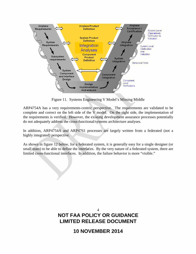
Figure 11. Systems Engineering V Model’s Missing Middle
ARP4754A has a very requirements-centric perspective. The requirements are validated to be complete and correct on the left side of the V model. On the right side, the implementation of the requirements is verified. However, the existing development assurance processes potentially do not adequately address the cross-functional/systems architecture analyses. In addition, ARP4754A and ARP4761 processes are largely written from a federated (not a highly integrated) perspective. As shown in figure 12 below, for a federated system, it is generally easy for a single designer (or small team) to be able to define the interfaces. By the very nature of a federated system, there are limited cross-functional interfaces. In addition, the failure behavior is more “visible.”
5 NOT FAA POLICY OR GUIDANCE LIMITED RELEASE DOCUMENT
10 NOVEMBER 2014
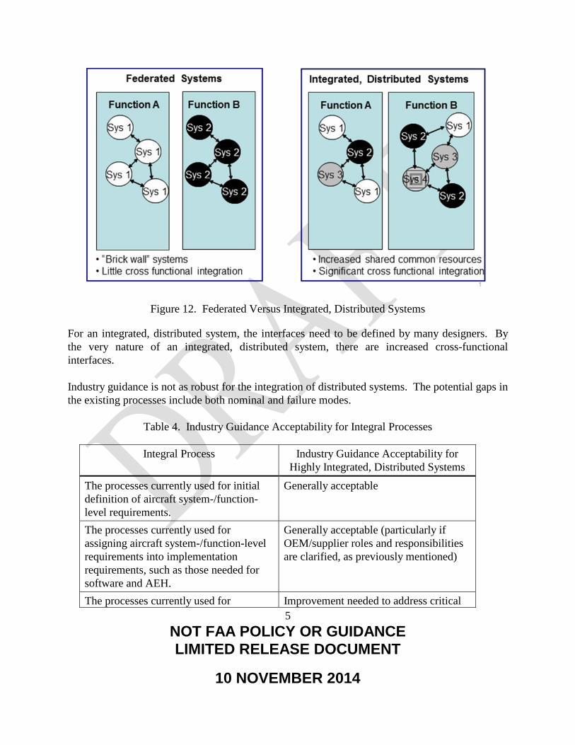
Figure 12. Federated Versus Integrated, Distributed Systems
For an integrated, distributed system, the interfaces need to be defined by many designers. By the very nature of an integrated, distributed system, there are increased cross-functional interfaces. Industry guidance is not as robust for the integration of distributed systems. The potential gaps in the existing processes include both nominal and failure modes.
Table 4. Industry Guidance Acceptability for Integral Processes
Integral Process Industry Guidance Acceptability for Highly Integrated, Distributed Systems
The processes currently used for initial definition of aircraft system-/function-level requirements.
Generally acceptable
The processes currently used for assigning aircraft system-/function-level requirements into implementation requirements, such as those needed for software and AEH.
Generally acceptable (particularly if OEM/supplier roles and responsibilities are clarified, as previously mentioned)
The processes currently used for Improvement needed to address critical

6 NOT FAA POLICY OR GUIDANCE LIMITED RELEASE DOCUMENT
10 NOVEMBER 2014
Integral Process Industry Guidance Acceptability for Highly Integrated, Distributed Systems
validating single system-/function-level requirements, including pilot evaluation of aircraft-level operation.
gaps (ref. section 4.2.2.9 below)
The processes currently used for validating intersystem/cross-function requirements, including pilot evaluation of aircraft-level operation.
Improvement needed to address critical gaps (ref. section 4.2.2.10 below)
The processes currently used for identifying missing requirements.
Improvement needed to address critical gaps (ref. section 4.2.2.11 below)
The processes of using requirements-based testing for verification that the system/function operation is correct and complete.
Generally acceptable
4.2.2.9 Processes for Validating Single System-/Function-Level Requirements, Including Pilot Evaluation of Aircraft-Level Operation.
In general, the processes for validating single system-/function-level requirements are acceptable (from an individual system perspective). However, improvement is needed for the pilot evaluation of the aircraft-level operation for single system-/function-level requirements. This is particularly true for resource systems where the systems architecture is now very interrelated and highly integrated. The possibility exists that certain failure modes, which in a federated system may have had a limited effect on other systems, may now have a cascading effect on other systems. The resulting cascading effects affect the ability of the flight crew to cope with the situation and provide for safe operation of the airplane. The following generic example, as shown in figure 13, illustrates this process gap. This potentially catastrophic situation would not be found if one simply followed the existing industry guidelines (particularly ARP4754A [2] and ARP4761[7]).

7 NOT FAA POLICY OR GUIDANCE LIMITED RELEASE DOCUMENT
10 NOVEMBER 2014
Figure 13. Unacceptable, Cumulative Cascading Failure Effects
The simplified diagram above shows the results of the cascading failure effects of electrical component failures. The purpose is to illustrate how the stack up of the cumulative system-level effects needs to be understood to ensure that an adequate level of safety is maintained in the presence of failures. At each point, all of the failures are acceptable from a systems perspective (acceptable loss of redundancy). However, the cumulative effect of acceptable systems-level effects is catastrophic at the airplane level. (Note: This is for illustrative purposes only; aircraft systems would not be designed and certified this way). 4.2.2.10 Processes Currently Used for Validating Intersystem/Cross-Function Requirements, Including Pilot Evaluation of Aircraft-Level Operation.
There is room for improvement in the process guidance for the validation of intersystem/cross-function requirements. This occurs at multiple levels: • Subsystem-to-subsystem • Component-to-component • Message-to-message
Figure 14 shows the braking system for a more federated system. As expected, there are very few cross-functional interfaces. The basic elements include the spoiler handle, the brake system control unit, and the autobrake solenoid valve.

8 NOT FAA POLICY OR GUIDANCE LIMITED RELEASE DOCUMENT
10 NOVEMBER 2014
Figure 14. More Federated System
Figure 15 shows the same systems functionality, as implemented on a more integrated system. The same basic elements exist: spoiler handle, brake system control unit, and autobrake solenoid valve. However, there are significantly more cross-functional interfaces, for which better process guidance would be helpful.
Figure 15. More Integrated System
Another process gap is that there tends to be an assumption that if all of the airplane-level FHAs are acceptable, then the cumulative airplane-level effects of cascading effects will be acceptable. However, this is not a valid assumption for highly integrated systems.

9 NOT FAA POLICY OR GUIDANCE LIMITED RELEASE DOCUMENT
10 NOVEMBER 2014
4.2.2.11 Process for Validating Missing Requirements.
The process for validating missing requirements can be improved by • Establishing an approach to validate and verify the intrasystem functionality to determine
that functions perform as required:
− System functions within its boundaries, using known definitions of its interfaces/boundaries.
− Describe system behavior to interfacing systems.
• Establishing an approach to verification of the intersystem functionality to determine proper content and performance:
− System functions properly in relation to associated functionality provided by interfacing and/or interacting systems.
− Validation of assumptions made at the intrasystem level.
− Validation and verification of end-to-end functionality and end-to-end signal timing.
• Identifying aircraft-level failure modes and effects considerations:
− Identify single and combination failure conditions to analyze, targeting key integration components/functions to determine that the impacts of failures are as expected and are acceptable.
− Include resource systems:
o Power sources, power distribution systems (engine, electric, hydraulic, pneumatic) and data networks.
o Systems and/or control signals that affect multiple aircraft functions.
4.2.2.12 Process Gaps vs. Implementation Escapes.
It is not possible to have consistent, perpetual flawless execution of any process. The objectives of development assurance processes are to minimize safety errors that could adversely affect safety. However, no development assurance process can guarantee that there will be no development assurance errors.
10 NOT FAA POLICY OR GUIDANCE LIMITED RELEASE DOCUMENT
10 NOVEMBER 2014
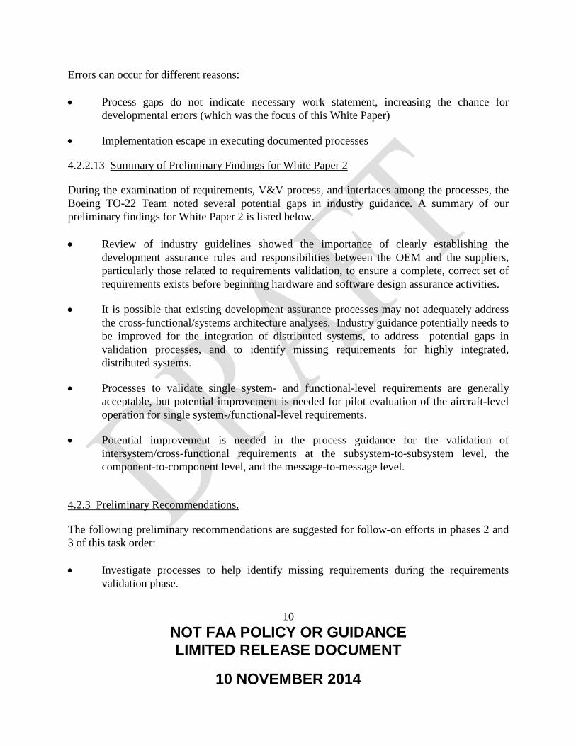
Errors can occur for different reasons: • Process gaps do not indicate necessary work statement, increasing the chance for
developmental errors (which was the focus of this White Paper)
• Implementation escape in executing documented processes
4.2.2.13 Summary of Preliminary Findings for White Paper 2
During the examination of requirements, V&V process, and interfaces among the processes, the Boeing TO-22 Team noted several potential gaps in industry guidance. A summary of our preliminary findings for White Paper 2 is listed below. • Review of industry guidelines showed the importance of clearly establishing the
development assurance roles and responsibilities between the OEM and the suppliers, particularly those related to requirements validation, to ensure a complete, correct set of requirements exists before beginning hardware and software design assurance activities.
• It is possible that existing development assurance processes may not adequately address the cross-functional/systems architecture analyses. Industry guidance potentially needs to be improved for the integration of distributed systems, to address potential gaps in validation processes, and to identify missing requirements for highly integrated, distributed systems.
• Processes to validate single system- and functional-level requirements are generally acceptable, but potential improvement is needed for pilot evaluation of the aircraft-level operation for single system-/functional-level requirements.
• Potential improvement is needed in the process guidance for the validation of intersystem/cross-functional requirements at the subsystem-to-subsystem level, the component-to-component level, and the message-to-message level.
4.2.3 Preliminary Recommendations.
The following preliminary recommendations are suggested for follow-on efforts in phases 2 and 3 of this task order: • Investigate processes to help identify missing requirements during the requirements
validation phase.
11 NOT FAA POLICY OR GUIDANCE LIMITED RELEASE DOCUMENT
10 NOVEMBER 2014
• Examine processes to ensure that OEMs and Suppliers are working to a complete and correct set of requirements to the greatest practical extent.
• Consider the potential need to clarify roles and responsibilities between OEMs and Suppliers potential regarding the transition from development assurance activities to design assurance activities (Note: It is recognized that this will vary based on the different business models).
• Identify potential gaps that may exist with processes to validate requirements for both single-system/function and intersystem/cross-function levels, including pilot evaluation of aircraft-level operation.
• Consider establishment of an approach to validate and verify intrasystem and intersystem functionality to determine that proper function, content, and performance exists. Include consideration of aircraft-level failure modes and effects.
4.3 WHITE PAPER 3.
White Paper 3 was the third and final of three white papers that addressed the TO-22 Phase 1 PWS “Identify issues and shortcomings of identified requirement definition, validation & verification processes, and interfaces” [1]. The following subsections address the research approach, preliminary findings, and preliminary recommendations. 4.3.1 Research Approach.
In its research approach, the Boeing TO-22 team • Identified possible issues and shortcomings with the requirements’ validation and
verification process.
• Classified issues and shortcomings, and determines root causes.
• Identified practical and implementable mitigations for the safe design, development, and V&V of complex, integrated digital aircraft.
The Boeing TO-22 Team also examined the eight potential scenarios listed in TO-22: 1. “The system-level requirement was incorrectly specified initially, and was implemented
per that requirement. The error was not discovered during the validation process, or else

12 NOT FAA POLICY OR GUIDANCE LIMITED RELEASE DOCUMENT
10 NOVEMBER 2014
the validation requirements at that level did not occur. This would be an example of a requirements’ error, as well an error in validation of that requirement.
2. Incorrect translation of a correct system-level requirement when assigning that requirement to a specific implementation. For example, a “+” input into a control law summing junction was incorrectly implemented as a “–” input. This would be an example of a requirement error, as well as an error in verification of that requirement. This differs from item 1, in that an error in the translation or transcription of requirements occurred. The initially defined requirement was correct.
3. A requirement that would have addressed an anomalous system operation was never specified. For example, the power-up process while the aircraft was in the air did not specify certain latches, counters, and inputs that were to be initialized. This would be an example of a requirements’ omission.
4. Requirements were correctly specified for normal operation but were not correctly specified for unexpected operation or for failure conditions (either single or multiple). This could include the situation where the system response to the unexpected operation or failure condition was specified but that response turned out to be undesirable, or the situation where the failure condition (or conditions) was (were) not anticipated, and therefore the system response was undefined. This could be an example of a requirements’ error and/or omission, as well as an error in requirements’ validation.
5. Requirements were correct for operations for an individual system or systems, but the operation of the two or more interfacing systems—during normal operations or during failure conditions—were incompatible with each other. This would be an example of a requirements’ conflict between two systems.
6. Cascading failure condition(s) through multiple aircraft systems or functions due to an initial failure or set of failures was (were) not correctly identified. This would be an example of the requirements for multiple systems not having been adequately validated, or possibly a requirements’ conflict between two or more aircraft systems.
7. System-level requirements did not correctly anticipate flight crew actions or responses to specific conditions or failures. For example, an autopilot design did not anticipate the flight crew making control inputs into the flight control system without first disconnecting the autopilot. This would be an instance of the requirement not being validated or possibly a requirements’ omission.
8. All system-level requirements were initially complete and correct. However, a change was made in one area, such as a specific aircraft system, function, or sub-function, and

13 NOT FAA POLICY OR GUIDANCE LIMITED RELEASE DOCUMENT
10 NOVEMBER 2014
that change was not adequately analyzed, such that the change adversely affected the operation of another aircraft system or function. This would be an instance of a requirements’ conflict. Additionally, although this is not in one of the identified lists of possible requirements’ problems, this is an instance of the system-level change impact analysis (CIA) not being performed completely or correctly.” [1]
In developing the research approach, the following framing questions were used: • What is the correct way to progress from higher level requirements to detailed software
development and ensure safety has been adequately addressed at all levels? (If not done correctly, this could result in requirements process related failures.)
− Was adequate development assurance conducted prior to DO-178 (software) and DO-254 (complex hardware) verification activities?
− What tasks and activities are required to ensure that requirements at all levels are complete and correct (consistent with DO-178 [9] and DO-254 [10] assumptions)?
− Are all system requirements fully and properly allocated to software requirements and software design?
The research approach included the following: • Reviewed flight test squawks, late design changes, and requirements “problems”
− Conducted root cause analysis
o Requirements error
o Requirements omission
o Requirements conflict
− Determined if process was not followed or if “process gap” exists
• Identified process gaps related to horizontal and vertical integration:
− Airplane-level V&V
− Intersystem V&V
− Intrasystem V&V

14 NOT FAA POLICY OR GUIDANCE LIMITED RELEASE DOCUMENT
10 NOVEMBER 2014
− Component-level V&V
− Robustness level of integrated V&V program, including robustness of testing at component, subsystem, system, and system of systems levels
The research focus was placed on the more complex scenarios where requirements were not properly validated or verified, or requirements did not exist at all. A critical part of requirements validation includes the completeness and correctness assessment. If requirements should exist but do not, it will not be possible to do validation and verification on these missing requirements. The robust and rigorous application of systems engineering processes provides an opportunity for the avoidance of missing requirements. It is important to acknowledge some of the more simplistic ways in which requirements errors can occur. • Safety analyses could be conducted, but the derived safety requirements are not captured.
As a result, they are never communicated to the design engineer.
• Relatively straightforward interactions between systems are not accurately captured. For example, line replaceable unit (LRU) B needs data at 50 ms or faster. LRU A is publishing the data at 25 ms. However, LRU A then makes a design change to publish the data at 75 ms. This change is not properly coordinated with LRU B and the result is not acceptable.
4.3.2 Preliminary Findings.
4.3.2.1 Assurance Processes.
The aerospace industry has an excellent safety record. To a large extent, this can be attributed to the safety culture that exists within the different manufacturers and suppliers. In addition, industry guidelines have been developed to help minimize development and design errors that could adversely affect safety. ARP4761 [7] provides a safety assessment process. ARP4754 [3], DO-178 [9], and DO-254 [10] are assurance processes; all use an assurance process with the level of process rigor determined by the failure classification. Assurance processes are implemented for complex and highly integrated systems because it is not possible to test 100% to demonstrate that there are no development errors. The purpose of robust assurance processes is to qualitatively mitigate the likelihood of not discovering and addressing development errors. Recent updates improved the integration of the different guidelines.

15 NOT FAA POLICY OR GUIDANCE LIMITED RELEASE DOCUMENT
10 NOVEMBER 2014
Having a robust development assurance is important. Due to their innate complexity, design architectures for integrated digital avionics systems pose a higher level of risk for development and design errors. As some errors may not be deterministic, suitable development assurance practices may be difficult to accomplish. Existing industry development assurance processes lay a basic framework extending from the system level down to the software and hardware level. ARP4754 Rev A [2] provides a development assurance process from the aircraft level to the item level. DO-178 and DO-254 provide development assurance processes, respectively, for software and airborne electronic hardware. 4.3.2.2 Application of Assurance Processes.
Even when companies use development assurance processes, there are still a number of problems that occur later in the program than desired. These problems occur even though the integral processes are followed: • Safety assessment • Development assurance level assignment • Requirements capture • Requirements validation • Configuration management • Certification and regulatory authority coordination After going through rigorous design, validation, and verification activities, problems can still occur during integration testing (or, after entry into service). This raises the question of whether the problem is due to • Incorrect application of existing guidelines (e.g., guidance is correct, complete and clear;
it simply needs to be consistently followed).
• Existing guidelines do not adequately address the more integrated nature of systems architectures.
The eight scenarios listed in TO-22 were identified as realistic. However, these scenarios should not be misconstrued to suggest there are systemic problems. Commercial aviation has a remarkable safety record.

16 NOT FAA POLICY OR GUIDANCE LIMITED RELEASE DOCUMENT
10 NOVEMBER 2014
4.3.2.3 Scenario #1.
In Scenario #1, the system-level requirement was initially specified incorrectly and implemented per that requirement. The error was not discovered during the validation process, or else the validation requirements at that level did not occur. This would be an example of a requirements error, as well an error in the validation of that requirement. An example is the transition time for the handshake between two systems. The requirement was reviewed by subject matter experts. They were knowledgeable and believed the requirement to be correct. However, during testing, it was determined that the handshake time between the two systems was too long and was adjusted accordingly. (Note: It is not believed that completing the ARP4754A validation questions would have discovered this requirement to be invalid.) 4.3.2.4 Scenario #2.
Scenario #2 involved incorrect translation of a correct system-level requirement when assigning that requirement to a specific implementation. For example, a “+” input into a control law summing junction was incorrectly implemented as a “–” input. This would be an example of a requirement error, as well as an error in the verification of that requirement. This differs from Scenario 1 in that an error in the translation or transcription of requirements occurred. The initially defined requirement was correct. A bug was introduced by way of a coding error when a data field was used without initialization. The data field was associated with the number of flights between operational tests. The data field is typically initialized when a system test is performed, but not otherwise. When a new software data load is performed to update the equipment, the field is not initialized. The coding error was in using an uninitialized space. Errors like this are typically discovered during peer reviews and testing. 4.3.2.5 Scenario #3.
In Scenario #3, a requirement that would have addressed an anomalous system operation was never specified. For example, the power-up process while the aircraft was in the air did not specify certain latches, counters, and inputs that were to be initialized. On 1 August 2005, at 17:03 Western Standard Time, a Boeing 777-200 operated by Malaysian Airline System, experienced a pitch up about 30 min after takeoff from Perth, Australia, while climbing through 36,000 ft with autopilot on.

17 NOT FAA POLICY OR GUIDANCE LIMITED RELEASE DOCUMENT
10 NOVEMBER 2014
During the pitch up, the aircraft climbed to 41,000 ft and the indicated airspeed dropped from 270 knots to 158 knots. The stick shaker and the stall warning indicator activated during the event. The flight landed uneventfully back at Perth. In June 2001, accelerometer #5 failed with erroneous high output values. The ADIRU disregards the accelerometer output values. The power cycle on the ADIRU occurs on each occasion the aircraft electrical system is shut down and restarted. In August 2005, accelerometer #6 fails. The latent software anomaly allows use of the previously failed accelerometer #5 output. The result is the in-flight upset. On 29 August 2005, the FAA issued emergency AD 2005-18-51 [6] to install ADIRU-03 software, stating that faulty ADIRU data could cause anomalies in 777 primary flight controls, autopilot, pilot displays, autobrakes, and autothrottles. The ATSB [5] concluded that a contributing safety factor was “an anomaly existed in the component software hierarchy that allowed inputs from a known faulty accelerometer to be processed by the ADIRU and used by the primary flight computer, autopilot and other aircraft systems.” 4.3.2.6 Scenario #4.
Scenario #4 involved requirements that were correctly specified for normal operation but were not correctly specified for unexpected operation or for failure conditions (either single or multiple). This could include the situation where the system response to the unexpected operation or failure condition was specified but that response turned out to be undesirable, or the situation where the failure condition (or conditions) was (were) not anticipated, and therefore the system response was undefined. This could be an example of a requirements’ error and/or omission, as well as an error in requirements’ validation. An example is pump reservoir rise/fall due to a dip in pump speed resulting from long power interrupts. Long power interrupts lead to dips in pump speed that cause a momentary rise/fall of the pump reservoir, with corresponding dips in pump current and loop pressure. The falling edge of the transient in the reservoir position is quick enough to initiate the leak detection/isolation logic, leading to nuisance leak indications. 4.3.2.7 Scenario #5.
Scenario #5 involved requirements that were correct for operations for an individual system or systems, but the operation of the two or more interfacing systems—during normal operations or

18 NOT FAA POLICY OR GUIDANCE LIMITED RELEASE DOCUMENT
10 NOVEMBER 2014
during failure conditions—were incompatible with each other. This would be an example of a requirements conflict between two systems. This scenario covers cases where the requirements are correct from a siloed systems perspective, but not from an integration perspective. This scenario can result in causing problems for interfacing systems (particularly in the presence of failures) and usually occurs during design changes. For example, if a system makes a design change to its voting algorithm, its effects would need to be understood and clearly communicated to other systems. 4.3.2.8 Scenario #6.
Scenario #6 involved cascading failure condition(s) through multiple aircraft systems or functions due to an initial failure or set of failures was (were) not correctly identified. This would be an example of the requirements for multiple systems not having been adequately validated, or possibly a requirements’ conflict between two or more aircraft systems. As systems architectures become more integrated, many systems functions that were typically separated with limited interdependence are now interrelated and highly integrated. The possibility exists that certain failure modes, which in a federated system may have limited effect on other systems, may now have cascading effects on other systems. It is important to validate that the flight crew will be able to cope with failures that result in multiple flight deck effects. Integration analyses and testing are necessary to validate the acceptability of failure modes, which may result in the following flight deck effects: • Highly integrated (e.g., Integrated Modular Avionics system, Electrical System, etc.) unit
failures that cause multiple, confusing, or cascading effects, alerts, unusable electronic checklists
• Burying time-sensitive alerts
• Display loss or inappropriate reversions
• Cascading effects from “simple” single failures, e.g., generator
• Loss of crew alerting
• Inability of crew to find correct checklist
Boeing developed processes to address gaps in existing industry guidelines. The cascading failure analyses support validation that the systems architecture integration on the airplane meets the airplane-level safety requirements. The implementation of Boeing’s processes identified

19 NOT FAA POLICY OR GUIDANCE LIMITED RELEASE DOCUMENT
10 NOVEMBER 2014
requirements changes, design changes (including software changes), wiring changes, crew procedure changes, and test changes. Boeing does not believe that it would have identified these required changes if it had simply followed ARP4754A and ARP4761. From the March 2011 issue of Boeing’s Frontiers magazine (Volume XI, Issue X), Chief Project Engineer Mike Sinnett described one of the tests that validated the cascading failure analyses:
“Sinnett described one particularly challenging test that demonstrates the overall robustness of the 787 design and its capability to maintain safe conditions in the presence of multiple failures. ‘We intentionally failed one of the three air-data systems that provide key information on speed and altitude,’ Sinnett explained. ‘After that, we caused the remaining two systems to disagree.’ When the two remaining systems disagree, it means there is no known valid source of speed and altitude data. That is when the backup systems kick in. ‘Pilots see an annotation that they are getting this information from backup systems, but they never lose data on the primary flight display,’ Sinnett continued. Altitude is provided from the GPS system. Known conditions from a variety of systems and inputs, including aircraft gross weight, angle of attack, high-lift configuration and other parameters, allow the airplane to back-calculate airspeed from the lift equation and display it on the flight deck. ‘This represents a significant advancement in safety and crew awareness in the presence of multiple failures,’ he said.” [17]
4.3.2.9 Scenario #7.
Scenario #7 involved system-level requirements that did not correctly anticipate flight crew actions or responses to specific conditions or failures. This scenario covers a deliberate action by the flight crew that was not necessarily anticipated by the system designers. (Note: It is understood that the designers can never fully protect an airplane from doing something totally wrong or unexpected, particularly if it is not consistent with crew procedures or training). For example, an autopilot design did not anticipate the flight crew making control inputs into the flight control system without first disconnecting the autopilot. On July 13, 1996, a McDonnell Douglas MD-11 experienced an inflight upset near Westerly, Rhode Island. On June 8, 1997, a different MD-11 experienced an inflight upset near Nagoya, Japan. Per NTSB Recommendations A-99-39-44, these inflight upsets were caused when the flight crewmembers made manual flight control inputs while the autopilot system was engaged. The pilots, per the airplane flight manual, should not have made manual flight control inputs when the autopilot is engaged. Doing so will result in a sudden and abrupt movement of some flight control surfaces; when the autopilot disengages, there will be an unpredictable airplane response.

20 NOT FAA POLICY OR GUIDANCE LIMITED RELEASE DOCUMENT
10 NOVEMBER 2014
In both inflight upsets, the crew members took actions that they believed were appropriate to address their concerns (in one case, concern that the airplane might not level off at assigned altitude, creating need to slow rate of descent; in the other case, concern that the airplane would accelerate beyond the maximum operating airspeed). However, in both cases, the crewmembers made manual control inputs prior to disengaging the autopilot. The NTSB recommendations ranged from revising airplane flight manuals/company flight manuals to improve awareness to requiring all new transport-category airplane autopilot systems to be designed to prevent flight upsets when manual inputs to the flight controls are made. 4.3.2.10 Scenario #8.
In Scenario #8, all system-level requirements were initially complete and correct. However, a change was made in one area, such as a specific aircraft system, function, or sub-function, and that change was not adequately analyzed so that the change adversely affected the operation of another aircraft system or function. This would be an instance of a requirements’ conflict. Additionally, although this is not in one of the identified lists of possible requirements’ problems (in the TO-22 performance work statement), this is an instance of the system-level CIA not being performed completely or correctly. These results are sometimes referred to as “change on change.” After a change is implemented in one system, it has unanticipated, unexpected effects on other systems, resulting in the need to drive additional changes. Having a robust change impact analysis is the best way to mitigate this issue. In general, this tended to happen when there was a subtlety in the design change implementation that was not clearly understood by all impacted systems. 4.3.2.11 Incomplete and Incorrect Requirements.
Extensive literature documents that incomplete and/or incorrect requirements cause or contribute to development errors. A simplistic (and unrealistic) response would be to “just get the requirements right” and that occurrences of the above scenarios (and their associated development errors) will be significantly minimized. However, it is important to acknowledge the difficulty of obtaining a “complete and correct” set of requirements. SAE ARP4754, “Certification Considerations for Highly-Integrated or Complex Aircraft Systems” [3] acknowledged it is virtually impossible to validate that requirements (and assumptions) are complete and correct for complex systems.

21 NOT FAA POLICY OR GUIDANCE LIMITED RELEASE DOCUMENT
10 NOVEMBER 2014
When requirements changes result in late design changes, it adversely affects cost and schedule. There is a vested interest throughout the aviation industry to have complete and correct requirements. However, that is easier said than done. No one intentionally has incorrect or incomplete requirements. Many of the existing guidelines focus on validating the existing requirements set. There are rather extensive guidelines on different methods for validating the completeness and correctness of requirements (e.g., recommended validation matrix questions or attributes). However, there is not a significant amount of guidance on how to identify “missing” requirements. To a certain extent, this becomes axiomatic. If the requirement were known, it would be captured and communicated. However, if the requirement is unknown, it is difficult to capture. Even with existing requirements, the potential exists for the requirement to be misinterpreted or misunderstood. Because most requirements are text based, there is always the possibility that two people will read it and reach different conclusions (i.e., not on the same page). This is one of several reasons why requirements reviews exist. Figure 16 shows a simplistic example in which a Flight Management System expert develops requirements, which, to the best of the individual’s ability, reflect a complete and correct set of requirements. This information is passed to the Flight Management software engineer, who develops the Flight Management software.
Figure 16. Abstraction/Mental Model to Software
The following steps are involved: • Capture • Communicate • Comprehend If there are any gaps in terms of capturing, communicating, or comprehending the requirements, it will increase the chance that requirements will be missed or misinterpreted.

22 NOT FAA POLICY OR GUIDANCE LIMITED RELEASE DOCUMENT
10 NOVEMBER 2014
With the increasing level of integration between aircraft functions and the systems that implement them (figure 17), one system may impose requirements on other systems (e.g., performance, design constraints). If this is not done correctly, it can increase the possibility of a development error.
Figure 17. Integrated Systems
In addition to needing to understand the “horizontal integration,” there is also a need to understand the “vertical integration.” As shown in figure 18, the development assurance processes are defined from a hierarchical system decomposition, going from aircraft to system to item. At each level, requirements are decomposed and derived. Higher level parent requirements are decomposed into lower level children requirements. In addition, some requirements may be derived directly from design decisions and are not directly traceable to higher level requirements. Safety analyses are conducted at each respective level, resulting in derived safety requirements. If there are any errors or omissions at the higher level, these can manifest in lower levels, resulting in undesirable or unpredicted behavior.

23 NOT FAA POLICY OR GUIDANCE LIMITED RELEASE DOCUMENT
10 NOVEMBER 2014
Figure 18. Vertical Integration of Requirements
DO-178 [9] and DO-254 [10] assume that a complete and correct set of requirements have been allocated to the software and airborne electronic hardware. The interactions between different systems, if not properly understood, can be a source of problems. 4.3.2.12 Summary of Preliminary Findings
Anything that involves humans can result in human errors. Discussions with software (SW) and AEH subject matter experts validated that errors can occur in software and AEH that are not related to higher level requirements errors or omissions (i.e., the requirements had been properly allocated to hardware and software, but there were errors in the detailed implementation). • Mistakes can happen anywhere in the development space.

24 NOT FAA POLICY OR GUIDANCE LIMITED RELEASE DOCUMENT
10 NOVEMBER 2014
• Design Assurance reviews can never be 100%.
• Design Assurance reviews still cannot guarantee a perfect product because the reviewer can make mistakes too. The purpose of having the robust processes in place is to minimize errors.
The research also revealed that there could be cases in which higher level requirements/constraints were not identified/communicated to the SW and AEH developers. From an industry guideline perspective, there is some room for improvement to mitigate this from occurring. The purpose of the ARP4754A [2] development assurance process is to address the increased integration of systems. Boeing has practical experience of validating and verifying complex and highly integrated systems. In addition, Boeing participated in the creation of Aerospace Information Report (AIR) 6110, Contiguous Aircraft/System Development Process Example [18]. The purpose of this AIR was to provide a practical example of an implementation of ARP4754A (and its interrelationships with ARP4761 [7]). This AIR, while consistent with ARP4754A guidance, lacked key integration activities. (The systems integration guidance contained in Section 4 of ARP4754A could be improved.) Additional research could examine the horizontal and vertical integration guidance provided in ARP4754A to assess whether additional guidance might be recommended. This research would also include potential process improvements in the direct links between ARP4754A and ARP4761, DO-178 [9], and DO-254 [10]. Stated differently, there is room for process improvement in industry guidelines related to horizontal and vertical integration: • Airplane-level validation and verification • Intersystem validation and verification • Intrasystem validation and verification • Component-level validation and verification From an industry guideline perspective, this could impact the robustness level of integrated V&V programs, including robustness of testing at component, subsystem, system, and system of systems levels. The systems architecture and integration activities are an integral contributor to development assurance. There are interfaces between the systems architecture and integration activities and the safety assessment activities. This interaction is important to identify design constraints for other interfacing systems (and their lower level hardware and software). As systems become

25 NOT FAA POLICY OR GUIDANCE LIMITED RELEASE DOCUMENT
10 NOVEMBER 2014
more integrated, it is more likely that systems will be levying requirements and constraints on other systems (more so than in a federated systems architecture). Improving/clarifying the interactions between system development and the safety assessment process (particularly related to the integration of different systems) could be beneficial. This is not meant to imply that manufacturers and suppliers have not developed internal processes to analyze the systems architecture at its different levels. It just acknowledges that this information is not explicitly or clearly contained in the existing industry guidelines. If this is not done correctly, it increases the likelihood that DO-178 and DO-254 will not begin with a complete and correct set of requirements. As has been observed in numerous articles, the software is generally doing exactly what it was designed to do (which also supports the general adequacy of DO-178). When there are problems, they are usually caused by flawed (incomplete or incorrect) requirements. White Paper 2 contained additional information on methods to help validate missing requirements from an integration perspective. Another area of improvement in ARP4754A is providing additional guidance on the modification of existing systems. The majority of ARP4754A is written as if the system being developed is a “clean sheet” system. However, most systems are either modifying an existing system or using an existing system in a new environment. (Again, this is not meant to imply that manufacturers and suppliers have not developed their internal change impact assessment processes to support this type of activity; it is just an acknowledgement that there is a potential area for improvement in the industry guidelines). The final recommended area for further investigation is identifying when the existing guidelines would not be adequate for the more integrated systems. For example, the Boeing TO-22 Team identified cases in which • All of the failures (first order and cascading effects) are acceptable from a systems
perspective (acceptable loss of redundancy, degraded performance, etc.). However, the cumulative effect of acceptable systems-level effects is catastrophic at the airplane level.
• All of the failures (first order and cascading effects) are acceptable for a given airplane level FHA. Cumulative effect of acceptable, individual airplane level FHA is catastrophic when viewed from a multi-airplane level FHA perspective.
Boeing recognized process gaps in the existing industry guidelines (particularly ARP4754A and ARP4761). It does not believe that it would have found systems architecture deficiencies for highly integrated systems if it had simply followed industry guidelines.

26 NOT FAA POLICY OR GUIDANCE LIMITED RELEASE DOCUMENT
10 NOVEMBER 2014
4.3.3 Preliminary Recommendations.
The following preliminary recommendations are suggested for follow-on efforts in phases 2 and 3 of this task order: • Investigate the potential need to improve horizontal and vertical integration for V&V
processes at the component, intrasystem, intersystem, and airplane level.
• Investigate potential process improvements to facilitate requirements validation for the modification of existing systems.
• Consider potential process improvements to address cumulative effects of otherwise acceptable individual systems-level cascading effects.
5. SUMMARY OF WHITE PAPERS, PHASE 1 PRELIMINARY FINDINGS, AND RECOMMENDATIONS FOR CONTINUATION OF PHASES 2 AND 3.
White Paper 1 researched various information sources to identify adverse events in which the requirements definition and V&V may have been a contributing factor. A number of potential candidates were evaluated and rejected because they did not meet specific criteria. Following this process, Boeing TO-22 Team recommended that the 2005 Malaysian Airlines 777 Incident be used for further research. White Paper 2 examined requirements, V&V processes, and interfaces among the processes. The findings from the research showed there are potential improvements in industry guidance related to the roles and responsibilities of the OEM and supplier related to requirements validation. In addition, there are potential process improvements to address cross-functional/systems architecture analyses from a highly integrated, distributed systems’ perspective. Furthermore, there is a potential need to improve guidance for both single system-level requirements and functional-level requirements. White Paper 3 examined issues and shortcomings related to requirements’ definition, V&V processes, and interfaces, especially in scenarios where requirements were not properly validated or verified, or requirements did not exist at all. The findings showed there may be room for process improvement in industry validation and verification guidelines related to horizontal and vertical integration at the airplane, intersystem, intrasystem, and component levels.

27 NOT FAA POLICY OR GUIDANCE LIMITED RELEASE DOCUMENT
10 NOVEMBER 2014
5.1 SUMMARY OF PHASE 1 PRELIMINARY FINDINGS
• The 2005 Malaysian Airlines 777 Incident has elements of cascading effects across multiple integrated systems that make it an excellent event for further research (White Paper 1 finding).
• Review of industry guidelines showed the importance of clearly establishing the development assurance roles and responsibilities between the OEM and the suppliers, particularly those related to requirements validation, to ensure a complete, correct set of requirements exists before beginning hardware and software design assurance activities (White Paper 2 finding).
• It is possible that existing development assurance processes may not adequately address the cross-functional/systems architecture integration. Industry guidance potentially needs to be improved for the integration of distributed systems to address potential gaps in validation processes and to identify missing requirements for highly integrated, distributed systems (White Paper 2 finding).
• Processes to validate single system-level and functional-level requirements are generally acceptable, but potential improvement is needed for pilot evaluation of the aircraft-level operation for single system-level and functional-level requirements (White Paper 2 finding).
• Potential improvement is needed in the process guidance for the validation of intersystem/cross-functional requirements at the subsystem-to-subsystem level, the component-to-component level, and the message-to-message level (White Paper 2 finding).
• The V&V processes at the component, intrasystem, intersystem, and airplane level may require improvements for horizontal and vertical integration (White Paper 3 finding).
• Existing processes to facilitate requirements validation for the modification of existing systems may have gaps (White Paper 3 finding).
• Existing processes may not address cumulative effects of otherwise acceptable individual systems-level cascading effects (White Paper 3 finding).
5.2 SUMMARY OF PRELIMINARY RECOMMENDATIONS
28 NOT FAA POLICY OR GUIDANCE LIMITED RELEASE DOCUMENT
10 NOVEMBER 2014
The research conducted in Phase 1 led to the following preliminary recommendations: 1. Boeing recommended that the Malaysian Airline 777 pitch-up incident (summarized in
White Paper 1) be utilized for further research in TO-22, along with the additional scenarios evaluated as part of White Paper 3.
2. Investigate processes to help identify missing requirements during the requirements validation phase (summarized in White Paper 2).
3. Examine processes to ensure that OEMs and Suppliers are working to a complete and correct set of requirements to the greatest practical extent (summarized in White Paper 2).
4. Consider the potential need to clarify roles and responsibilities between OEMs and Suppliers potential regarding the transition from development assurance activities to design assurance activities (Note: It is recognized that this clarification will vary based on the different business models) (summarized in White Paper 2).
5. Identify potential gaps that may exist with processes to validate requirements for both single-system/function and intersystem/cross-function levels, including pilot evaluation of aircraft-level operation (summarized in White Paper 2).
6. Consider establishment of an approach to validate and verify intrasystem functionality to determine that proper function, content, and performance exists. Include consideration of aircraft-level failure modes and effects (summarized in White Paper 2).
7. Investigate the potential need to improve horizontal and vertical integration for V&V processes at the component, intrasystem, intersystem, and airplane level (summarized in White Paper 3).
8. Investigate potential process improvements to facilitate requirements’ validation for the modification of existing systems (summarized in White Paper 3).
9. Consider potential process improvements to address cumulative effects of otherwise acceptable individual systems-level cascading effects (summarized in White Paper 3).
Each of these preliminary recommendations suggests that additional research be conducted in optional Phases 2 and 3 of TO-22. Boeing’s approach to the research required by Phase 2 would involve a continuation of the systems engineering approach used in Phase 1 to classify and categorize the identified issues from Phase 1 and identify associated root causes of the requirements’ shortcomings. This work

29 NOT FAA POLICY OR GUIDANCE LIMITED RELEASE DOCUMENT
10 NOVEMBER 2014
would involve an analysis of example scenarios (delineated in Phase 1- DS 6 - White Paper 3) to identify possible gaps and contributing factors and associated root cause(s). Boeing’s approach to the research required by Phase 3 would likewise involve a continuation of the systems engineering approach utilized in Phase 1 to identify recommendations for possible solutions to the root cause(s) identified in Phase 2. This approach would involve an evaluation of current industry guidance and practices (outlined in Phase 1- DS 5 - White Paper 2) to formulate recommendations. The current state would be summarized, followed by a build-up and step-by-step description of implementing the possible solutions. 6. REFERENCES.
1. SE2020-TORP 1380-Task Order 0022-Modification 0001, “Safety Issues with Requirements Definition, Validation, and Verification Processes and Practices,” DTFAWA-10-D-00019, April 11, 2014.
2. SAE ARP4754A/EUROCAE ED-79A, “Guidelines for Development of Civil Aircraft and Systems,” December 21, 2010.
3. SAE ARP4754/EUROCAE ED-79, “Certification Considerations for Highly Integrated or Complex Aircraft Systems.” 1996.
4. Boyd, S., “SA-24 – B787 Unique Flight Deck Failure Modes and Effects,” 787 Issue Paper, Project Number TC6918SE-T, November 18, 2005.
5. Australian Transport Safety Bureau (ATSB), Transport Safety Investigation Report, Aviation Occurrence Report – 200503722 Final, August 1, 2005.
6. AD 2005-18-51, Federal Aviation Administration, September 9, 2005.
7. SAE ARP 4761, “Guidelines and Methods for Conducting the Safety Assessment Process on Civil Airborne Systems,” 1996.
8. DO-297, “Integrated Modular Avionics (IMA) Development Guidance and Certification Considerations,” RTCA Inc., Washington, DC, November 8, 2005.
9. DO-178B/C, “Software Considerations in Airborne Systems and Equipment Certification,” RTCA Inc., Washington, DC, 2001.

30 NOT FAA POLICY OR GUIDANCE LIMITED RELEASE DOCUMENT
10 NOVEMBER 2014
10. DO-254, “Design Assurance Guidance for Airborne Electronic Hardware,” RTCA Inc., Washington, DC, April 19, 2000.
11. AD 2014-06-04, Federal Aviation Administration, June 4, 2014.
12. AD 2012-21-08, Federal Aviation Administration, November 27, 2012.
13. AC20-115C, “Airborne Software Assurance,” Federal Aviation Administration, July 19, 2013.
14. AC20-152, “RTCA, Inc., Document RTCA/DO-254, Design Assurance Guidance for Airborne Electronic Hardware,” Federal Aviation Administration, June 30, 2005.
15. AC20-174, “Development of Civil Aircraft and Systems,” Federal Aviation Administration, September 30, 2011.
16. Skaves, Peter, “Applicability / Compatibility of STPA with FAA Regulations & Guidance,” available at http://psas.scripts.mit.edu/home/get_pdf.php?name=2-9-Skaves-Applicability-Compatibility-of-STPA-with-FAA-Regulations-and-Guidance.pdf (accessed on 08/26/14).
17. Gunter, Lori, 2011, “Dream flights: Extreme measures,” Boeing Frontiers, Vol. IX, Issue X, pp. 34-36.
18. SAE, SAI AIR6110, “Contiguous Aircraft/System Development Process Example,” December 16, 2011.
19. FAA, “Lessons Learned From Transport Airplane Accidents,” available at: http://lessonslearned.faa.gov/ (accessed on 08/26/14).
20. AC25.1701-1, “Certification of Electrical Wiring Interconnection Systems on Transport Category Airplanes,” Federal Aviation Administration, December 4, 2007.
21. AD 2005-19-19, Federal Aviation Administration, September 12, 2005.