Embed Size (px)
Citation preview

WildcatHigh Density Connectors
Innovative Interconnection Solutions

Contents
Introduction 3
Wildcat Micro 4
Contact Arrangement 5
Dimensional Information 5-9
Hermetic Receptacles 8
Triple Start Threaded 9
Contact and Tooling Information 9
Accessories Information 9
Ordering Information 10
Wildcat Series 3 11
Contact Arrangement 12
Dimensional Information 12-13
Contact and Tooling Information 13
Accessories Information 14
Ordering Information 14
Wildcat Capability 15

WildcatWildcat is a range of high performance circularconnectors from Deutsch specifically designedfor harsh environment applications where spaceand weight saving are of critical importance.The extremely high density contact layoutaffords almost double the number ofconnections found in similar sized connectorsyet retains the high performance expected for aerospace and military applications.
The connector housings for the ‘Wildcat Series3’ are based on the proven military standard‘MIL-DTL-38999 Series 3’ with the range further complimented by a miniature sized‘Micro’ series offering a significant reduction in shell size with a number of high densitycontact layouts.
3
Wildcat MicroThese extremely compact connectors are based on the proven
HDJ / JN1003 range and are available in two housing sizes with
four contact layouts with between 3 and 9 contacts.
A robust bayonet mechanism enables quick and positive coupling
with an anti-vibration triple-start threaded option also available.
Various mounting options are available and the rear accessory
feature provides for cable braid and boot termination.
Wildcat Series 3Based on MIL-DTL-38999 Series 3 technology the connectors are
available in four housing sizes with between 11 and 64 contacts
which provide almost double the contact density for a given 38999
connector size. The triple-start threaded interface provides a robust
and high-reliability coupling mechanism with a high level of
resistance to shock and vibration.
Mounting and rear accessory options are available enabling either
backshell or cable braid and boot termination. As with the Micro
series, the connectors are fully sealed with rear removable contacts
and available in various plating and material finishes.

Features
• Robust design and construction
• High density contact spacing
• Lightweight materials
• Material and plating options
• 4 contact layout options
• Bayonet and threaded coupling
• Scalloped / knurled coupling ring
• Scoop proof interface
• 3-5 Amps per contact
• Rear removable crimp and PCB contacts
• Various plating and material options
• Cable braid and boot rear feature
• Fully sealed cable and mating interface
• 7 keying options including ‘Universal’
• Various flange mounting options
Benefits
• High reliability interconnection for demandingapplications including military and aerospace
• Extreme temperature, vibration and corrosion resistance
• Provides space and weight savings over other connectors
• High number of mating cycles
• Bayonet provides quick positive locking
• Easy-grip coupling ring
• Suitable for both signal and low power applications
• Versatility through material and plating options
• Rear feature eliminates need for backshells
• Aggressive fluid and dust ingress prevention
• Keying prevents mating with incorrect connector
General Specification
Performance
• Temperature: -55°C to +170°C
• Durability: >500 cycles of engagement and disengagement
• Dielectric Withstand Voltage: 1000VAC
• Vibration: Sinusoidal 10 to 2000Hz. 30g Max. Random 50 to 2000Hz. 1g2/Hz.
• Fluid resistance: Connectors show no damage whenexposed to a wide range of military and aerospace fluids
• Salt spray resistance: 500 hours (Cadmium finish)
• Sealing: IP67
Housing materials
• Shell and coupling ring: Aerospace grade aluminium alloy as standard
• Plating: Cadmium olive drab as standard
• For other material and plating options see Wildcat Micro ordering information
• Seals: Fluorinated silicone
• Insulators: High performance thermoplastic
Contacts
• Machined from solid bar
• Gold plated copper alloy
• Crimp and PCB types
• Wire size: 22 to 28AWG (see contact table)
• Current: 3 to 5 Amps (see contact table)
Company Quality Approvals
• EASA Part 21
• BS EN 9100 / AS 9100 / ISO 9001
• Military Specification Approvals
• Underwriters Laboratories
• BS EN ISO 14001
• NADCAP Approval
Wildcat Micro
4

06-05 06-0903-03 03-05
Shell size 03 Shell size 06
Contact Arrangement
Square Flange Receptacle – Shell Type 0
Dimensional Information All measurements are supplied in mm and inches. Inches are indicated on all tables by red italic text.
5
Shell Size A Max ØB Max ØC Max D Max E Max F Max G ØH Min ØX ØY Z
0318.20 9.15 8.20 9.10 1.50 16.40 11.46 2.50 11.00 3.10 11.46
0.717 0.360 0.323 0.358 0.059 0.646 0.451 0.098 0.433 0.122 0.451
0620.45 11.15 10.05 11.10 1.50 18.20 12.70 2.50 13.00 3.10 12.70
0.805 0.439 0.396 0.437 0.059 0.717 0.500 0.098 0.512 0.122 0.500
Square Flange Receptacle
Layout P/N Option Contact Part No. A B ØC ØDCode Tail Pins Sockets Max Min Max Max Max
03-03-110 LONG 605679-31 605681
15.03 13.92 3.05 0.70 1.230.592 0.548 0.120 0.028 0.048
-111 SHORT 610292-31 6109449.83 8.72 3.05 0.70 1.230.387 0.343 0.120 0.028 0.048
03-05-120 LONG 610006-31 610008
15.71 14.58 3.05 0.57 0.940.619 0.574 0.120 0.022 0.037
-121 SHORT 610294-31 61094510.71 9.58 3.05 0.57 0.940.422 0.377 0.120 0.022 0.037
06-05-130 LONG 604990-31 604992
14.91 14.12 3.05 0.57 1.260.587 0.556 0.120 0.022 0.050
-131 SHORT 610293-31 6109169.91 8.12 3.05 0.57 1.260.390 0.320 0.120 0.022 0.050
06-09-140 LONG 610006-31 610008
14.92 14.14 3.05 0.57 0.940.587 0.557 0.120 0.022 0.037
-141 SHORT 610294-31 6109459.92 9.14 3.05 0.57 0.940.391 0.360 0.120 0.022 0.037
PCB Tail Dimensions
6
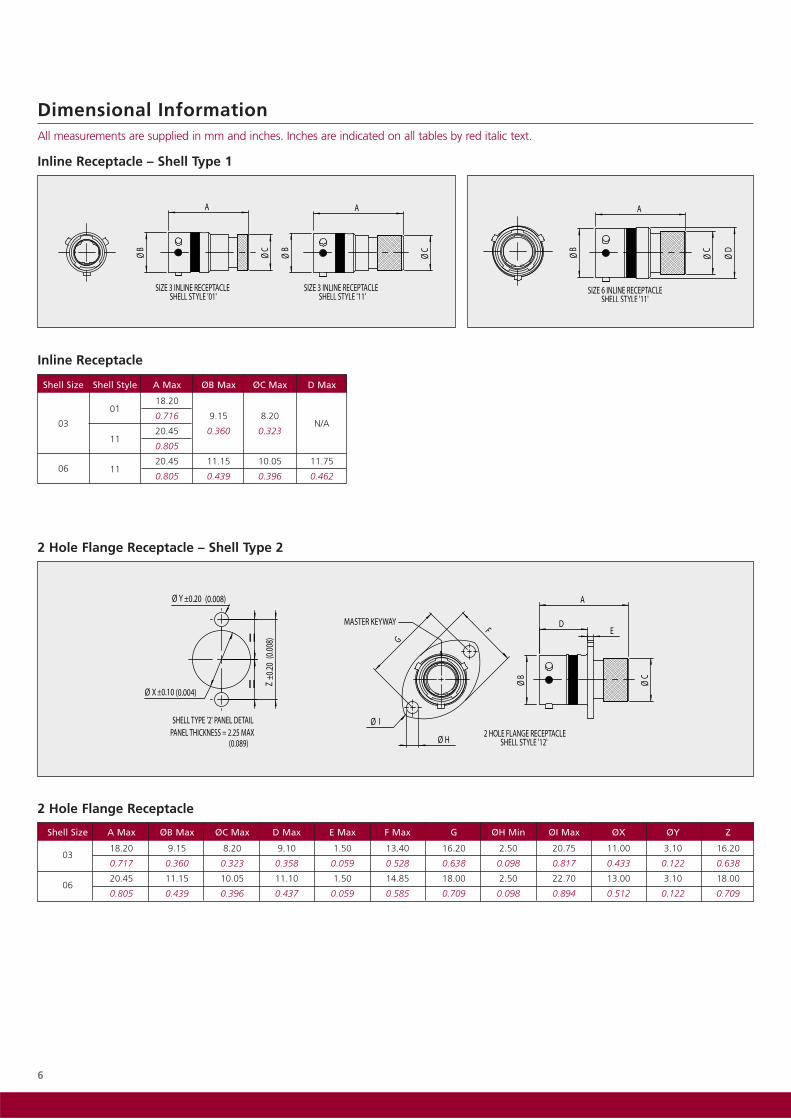
Inline Receptacle
2 Hole Flange Receptacle – Shell Type 2
Shell Size A Max ØB Max ØC Max D Max E Max F Max G ØH Min ØI Max ØX ØY Z
0318.20 9.15 8.20 9.10 1.50 13.40 16.20 2.50 20.75 11.00 3.10 16.20
0.717 0.360 0.323 0.358 0.059 0.528 0.638 0.098 0.817 0.433 0.122 0.638
0620.45 11.15 10.05 11.10 1.50 14.85 18.00 2.50 22.70 13.00 3.10 18.00
0.805 0.439 0.396 0.437 0.059 0.585 0.709 0.098 0.894 0.512 0.122 0.709
2 Hole Flange Receptacle
Shell Size Shell Style A Max ØB Max ØC Max D Max
03
0118.20
N/A0.716 9.15 8.20
1120.45 0.360 0.323
0.805
06 1120.45 11.15 10.05 11.75
0.805 0.439 0.396 0.462
Dimensional Information All measurements are supplied in mm and inches. Inches are indicated on all tables by red italic text.
Inline Receptacle – Shell Type 1

7
Dimensional Information All measurements are supplied in mm and inches. Inches are indicated on all tables by red italic text.
Jam Nut Receptacle – Shell Type 4
Free Plug – Shell Type 6
Jam Nut Receptacle
Shell Size Shell Style A Max ØB Max ØC Max D Max E Max F Max G Max ØH Max ØX Y
03
0418.20
0.717 9.15 8.20 11.60 19.00 17.10 21.15 12.20 11.82
1421.50 0.360 0.323 0.457 0.748 0.673 0.833 0.480 0.465
0.846 2.35
06
0420.45 0.093
0.805 11.15 10.05 11.70 21.00 19.25 23.15 16.57 15.51
1423.75 0.439 0.396 0.461 0.827 0.758 0.911 0.652 0.611
0.935
Free Plug
ØD Max
Shell Size Shell Style A Max ØB Max ØC Max Scalloped Knurled(Standard) (Option Code
‘KCR’)
03
0618.50
0.728 12.50 7.75 12.45 11.40
1622.45 0.492 0.305 0.490 0.449
0.884
06
0619.40
0.764 15.15 10.00 15.10 13.55
1623.00 0.596 0.394 0.594 0.533
0.906
8
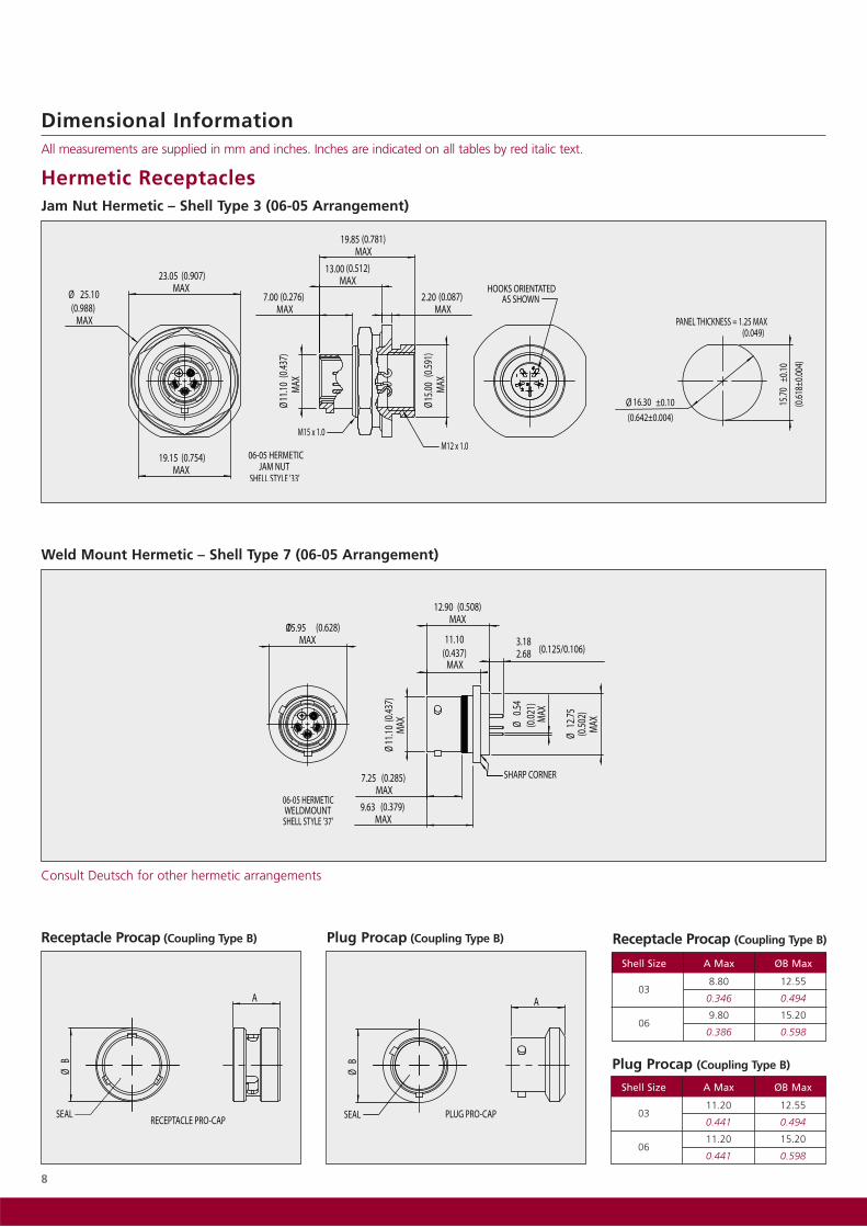
Dimensional Information All measurements are supplied in mm and inches. Inches are indicated on all tables by red italic text.
Receptacle Procap (Coupling Type B) Plug Procap (Coupling Type B)
Shell Size A Max ØB Max
0311.20 12.55
0.441 0.494
0611.20 15.20
0.441 0.598
Shell Size A Max ØB Max
038.80 12.55
0.346 0.494
069.80 15.20
0.386 0.598
Receptacle Procap (Coupling Type B)
Plug Procap (Coupling Type B)
Weld Mount Hermetic – Shell Type 7 (06-05 Arrangement)
Jam Nut Hermetic – Shell Type 3 (06-05 Arrangement)
Hermetic Receptacles
Consult Deutsch for other hermetic arrangements

LayoutContact Current Wire Size Conductor Wire Sealing Range
Filler Plug Ins/Ext Tool Crimp ToolPositioner
Pin Socket Rating (AWG) Min Ømm Max Ømm Min Ømm Max Ømm Pin Socket
03-03 604946-31 604984 5 AMPS 22-260.32 0.79 0.60 1.37
600300-22 M81969/14-01 605463 6054640.013 0.031 0.030 0.054
03-05 605705-31 605704 3 AMPS 24-280.25 0.51 0.60 0.96
600300-24 605837M22520/2-01
605839 6058400.010 0.020 0.024 0.038
06-05 604927-31 604935 3 AMPS 22-260.32 0.79 0.60 1.37
600300-22 M81969/14-01 604972 6049730.013 0.031 0.024 0.054
06-09 605705-31 605704 3 AMPS 24-280.25 0.51 0.60 0.96
600300-24 605837 605839 6058400.010 0.020 0.024 0.038
06-09* 610760 610539 3 AMPS 22-260.25 0.51 0.60 0.96
600300-24 Non-Removable M22520/2-01 610948 6109470.010 0.020 0.024 0.038
9
Dimensional Information All measurements are supplied in mm and inches. Inches are indicated on all tables by red italic text.
Accessories Information
Shell SizeStraight Boot 90˚ Boot
Raychem Hellerman Raychem Hellerman
03 204W221-25-G03 1037-4-G 224W221-25-G03 1182-4-G
06 204W221 1030-4-G 224W221 1181-4-G
ConnectorProtective Cap
Receptacle Plug03-3 way 605684-12 605687-12
03-5 way 605684-12 605687-12
06-5 way 604029-12 604027-12
06-9 way 604029-12 604027-12
Free Plug Threaded – Shell Type 6
Shell Size A Max ØB Max ØC Max
0624.65 16.75 10.05
0.970 0.659 0.396
Plug
Square Flange Receptacle Threaded – Shell Type 0
Triple Start Threaded
Shell Size A Max ØB Max ØC Max D Max E Max F Max G ØH Min
0622.45 13.85 10.05 13.10 1.50 20.20 15.00 2.50
0.884 0.545 0.396 0.516 0.059 0.795 0.590 0.098
Square Flange Receptacle
Contact and Tooling Information
*Specifically for the '-220' option code. -220 option code should be used to order with these contacts for 22 AWG wire (see ordering information).
-12 = Cadmium olive drab, -58 = Nickel

10
Ordering Information
Series:Wildcat Micro
Shell Rear Accessory:0 = Short Knurl - Boot Mounting (Short Knurl not available for Shell Type 0, Type 1 (Shell Size 06) or Type 2)
1 = Long Knurl - Cable Screen Braid and Boot Mounting
3 = No Accessory (e.g. Hermetic Box Mount)
Shell Type:0 = Square Flange Receptacle
1 = In-line Receptacle
2 = 2 Hole Flange Receptacle
3 = Hermetic Jam Nut
4 = Jam Nut Receptacle
6 = Free Plug
7 = Hermetic Weld Mount
Coupling Type:B = Bayonet
T = Triple-start ACME Thread
Class Code:W = Aluminium with Olive Drab Cadmium
F = Aluminium with Electroless Nickel
Z = Aluminium with Zinc Cobalt
D = Aluminium with Zinc Nickel
S = Stainless Steel, Nickel Plated
K = Stainless Steel, Passivated
B = Aluminium Bronze
G = Space Grade
Shell Size - Insert Arrangement:03-03 = Shell Size 3, 3 way
03-05 = Shell Size 3, 5 way
06-05 = Shell Size 6, 5 way
06-09 = Shell Size 6, 9 way
Contact Type:P = Pin
S = Socket
Keying:N = Normal
U = Universal
A, B, C, D, E
Option Code (3 digits) or Modification Code:090 = Supplied without Contacts
1xx = PCB Contact (see PCB option table for code)
220 = Crimp Contacts for #22AWG Wire (non-removable, ordered with 06-09 only)
Sxx = Space Application (consult factory for code)
Part Number Example: WM 0 6 B W 06-05 S N - ****

Features
• Based on proven MIL-DTL-38999 S3
• High density contact spacing
• Lightweight materials
• Material and plating options
• 4 high density contact layout options
• Threaded anti-vibration coupling
• Scoop proof interface
• 3 Amps per contact
• Rear removable crimp and PCB contacts (consult Deutsch for PCB details)
• Various plating and material options
• Backshell or cable braid/boot rear feature
• Fully sealed cable and mating interface
• 7 keying options including ‘Universal’
• RFI mating interface band
Benefits
• High reliability interconnection for demandingapplications including military and aerospace
• Extreme temperature, vibration and corrosion resistance
• Versatility through material & plating options
• Reduce the size or number of connectors with almostdouble the contact density of MIL-DTL-38999 connectors
• High number of mating cycles
• Rapid and positive coupling
• Easy-grip coupling ring
• Suitable for both signal and low power applications
• Boot feature eliminates need for backshells
• Aggressive fluid and dust ingress prevention
• Keying prevents mating with incorrect connector
• EMI screening as per MIL-DTL-38999 S3
General Specification
Performance
• Temperature: -65°C to +175°C (Cadmium)-65°C to +200°C (Nickel)
• Thermal Shock: As per MIL-DTL-38999 S3
• Durability: >500 cycles of engagement and disengagement
• Dielectric Withstand Voltage: 1000VAC
• Vibration: As per MIL-DTL-38999 S3
• Shock: 300g, 3ms in 3 axes
• Fluid resistance: Connectors show no damage whenexposed to a wide range of military and aerospace fluids
• Salt spray resistance: 500 hours (Cadmium finish) per MIL-STD-1344 Method 100 B and NFC93422. 48 hours(Nickel finish)
• Sealing: Up to 30,000 metres/100,000ft altitude
Housing materials
• Shell and coupling ring: Aerospace grade aluminium alloy as standard
• Plating: Cadmium olive drab as standard
• For other material and plating options see Wildcat S3ordering information
• Seals: Fluorinated silicone
• Insulators: High performance thermoplastic
Contacts
• Machined from solid bar
• Gold plated copper alloy
• Crimp type
• Wire size: 24 to 28AWG
• Current rating: 3 Amps
Company Quality Approvals
• EASA Part 21
• BS EN 9100 / AS 9100 / ISO 9001
• Military Specification Approvals
• Underwriters Laboratories
• BS EN ISO 14001
• NADCAP Approval
Wildcat Series 3
11

Shell Size A Max B Max ØC Max D Max E Max
0924.00 11.30
0.945 0.445
1126.40 14.35
1.039 33.80 0.565 19.90 2.50
1328.90 1.331 17.50 0.783 0.098
1.138 0.689
1531.30 20.65
1.232 0.813
12
Contact Arrangement
Dimensional Information All measurements are supplied in mm and inches. Inches are indicated on all tables by red italic text.
Shell size 09 Shell size 11 Shell size 13 Shell size 15
09-11 11-23 13-41 15-64
Square Flange Receptacle – Shell Type 0
Shell Size A Max B Max D Max E Max Thread ‘T’
0924.00
M12x1.0 - 6g0.945
1126.40
M15x1.0 - 6g1.039 31.55 19.90 2.50
1328.90 1.242 0.783 0.098
M18x1.0 - 6g1.138
1531.30
M22x1.0 - 6g1.232
Square Flange Receptacle with Accessory Thread Square Flange Receptacle with Knurled Rear
Jam Nut Receptacle – Shell Type 4

LayoutContact Current Wire Size Conductor Wire Sealing Range
Filler Plug Ins/Ext Tool Crimp ToolPositioner
Pin Socket Rating (AWG) Min Ømm Max Ømm Min Ømm Max Ømm Pin Socket
09-11
605719-31 605721 3 AMPS 24-280.254 0.511 0.600 0.96
600300-24 605837 M22520/2-01 610286 61028711-23
13-41
15-64
0.010 0.020 0.024 0.038
13
Square Flange Panel Cutout Detail
Shell Size ØX YFront mtg Rear mtg Max Min
0913.11 16.66 18.26 15.09
0.516 0.656 0.719 0.594
1115.08 22.22 20.26 18.26
0.594 0.875 0.798 0.719
1319.05 23.42 23.01 20.62
0.750 0.922 0.906 0.812
1523.01 26.59 24.61 23.01
0.906 1.047 0.969 0.906
Dimensional Information All measurements are supplied in mm and inches. Inches are indicated on all tables by red italic text.
Free Plug – Shell Type 6
Shell Size A Max B Max C Max D Max E Max Thread ‘T’
0927.20 23.25
M12x1.0 - 6g1.071 0.915
1132.00 26.30
M15x1.0 - 6g1.260 32.55 1.035 22.40 2.95
1335.10 1.281 32.00 0.882 0.116
M18x1.0 - 6g1.382 1.260
1538.30 36.00
M22x1.0 - 6g1.508 1.417
Jam Nut Receptacle with Accessory ThreadØX Y
Shell Size +/-0.10 +/-0.10
0917.80 16.89
0.700 0.665
1120.98 19.43
0.826 0.765
1325.68 24.16
1.011 0.951
1528.90 27.43
1.138 1.080
Jam Nut Panel Cutout Detail
Shell Size ØA Max B Max ØC Max
0921.30 11.30
0.839 0.445
1123.75 14.35
0.935 33.30 0.565
1329.10 1.311 17.50
1.146 0.689
1532.30 27.00
1.272 1.063
Plug with Accessory Thread
Shell Size ØA Max B Max Thread ‘T’
0921.30
M12x1.0 - 6g0.839
1123.75
M15x1.0 - 6g0.935 31.10
1329.10 1.224
M18x1.0 - 6g1.146
1532.30
M22x1.0 - 6g1.272
Plug with Knurled Rear
Contact and Tooling Information

14
Procaps and Backshells
Wildcat S3 connectors are suitable for use withMIL-DTL-38999 S3 type backshells and procapsor equivalent.
Accessories Information
Shell SizeStraight Boot 90˚ Boot
Raychem Hellerman Raychem Hellerman
09 202K121 152-42-G 222K121 1152-4-G
11 202K132 152-42-G 222K121 1152-4-G
13 202K142 154-42-G 222K132 1154-4-G
15 202K142 155-42-G 222K142 1155-4-G
Ordering Information
Series:Wildcat Series 3
Shell Rear Accessory:1 = Braid and Boot Mounting Feature2 = Rear Accessory Thread, Anti-rotation Teeth
Shell Type:0 = Square Flange Receptacle4 = Jam Nut Receptacle6 = Free Plug
Coupling Type:T = Triple-start ACME Thread
Class Code:W = Aluminium with Olive Drab CadmiumF = Aluminium with Electroless NickelZ = Aluminium with Zinc CobaltD = Aluminium with Zinc NickelS = Stainless Steel, Nickel PlatedK = Stainless Steel, PassivatedB = Aluminium BronzeG = Space Grade
Shell Size - Insert Arrangement:09-11 = Shell Size 9, 11 way11-23 = Shell Size 11, 23 way13-41 = Shell Size 13, 41 way15-64 = Shell Size 15, 64 way
Contact Type:P = PinS = Socket
Keying:N = NormalU = UniversalA, B, C, D, E
Option Code (3 digits) or Modification Code:090 = Supplied without ContactsSxx = Space Application (consult factory for code)
Part Number Example: W3 1 6 T W 09-11 S N - ****
15
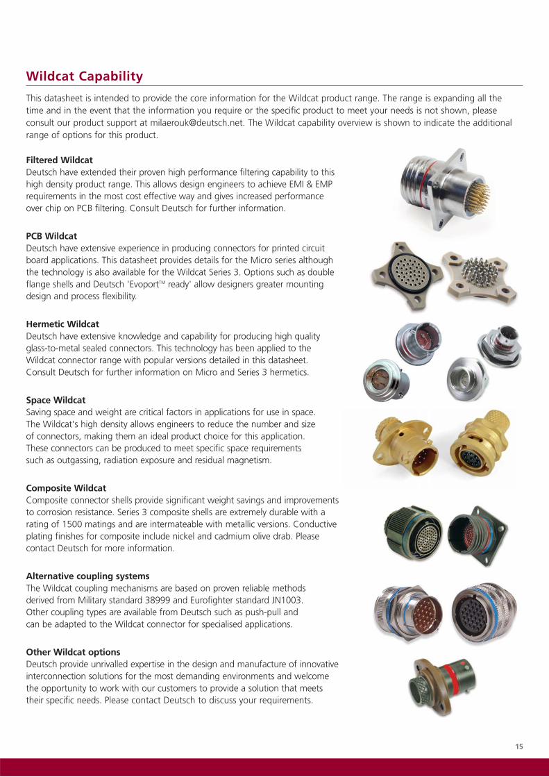
Filtered WildcatDeutsch have extended their proven high performance filtering capability to thishigh density product range. This allows design engineers to achieve EMI & EMPrequirements in the most cost effective way and gives increased performance over chip on PCB filtering. Consult Deutsch for further information.
PCB WildcatDeutsch have extensive experience in producing connectors for printed circuitboard applications. This datasheet provides details for the Micro series althoughthe technology is also available for the Wildcat Series 3. Options such as doubleflange shells and Deutsch 'EvoportTM ready' allow designers greater mountingdesign and process flexibility.
Hermetic WildcatDeutsch have extensive knowledge and capability for producing high quality glass-to-metal sealed connectors. This technology has been applied to the Wildcat connector range with popular versions detailed in this datasheet. Consult Deutsch for further information on Micro and Series 3 hermetics.
Space WildcatSaving space and weight are critical factors in applications for use in space. The Wildcat's high density allows engineers to reduce the number and size of connectors, making them an ideal product choice for this application. These connectors can be produced to meet specific space requirements such as outgassing, radiation exposure and residual magnetism.
Composite WildcatComposite connector shells provide significant weight savings and improvementsto corrosion resistance. Series 3 composite shells are extremely durable with arating of 1500 matings and are intermateable with metallic versions. Conductiveplating finishes for composite include nickel and cadmium olive drab. Pleasecontact Deutsch for more information.
Alternative coupling systemsThe Wildcat coupling mechanisms are based on proven reliable methods derived from Military standard 38999 and Eurofighter standard JN1003. Other coupling types are available from Deutsch such as push-pull and can be adapted to the Wildcat connector for specialised applications.
Other Wildcat optionsDeutsch provide unrivalled expertise in the design and manufacture of innovativeinterconnection solutions for the most demanding environments and welcome the opportunity to work with our customers to provide a solution that meets their specific needs. Please contact Deutsch to discuss your requirements.
Wildcat Capability
This datasheet is intended to provide the core information for the Wildcat product range. The range is expanding all the time and in the event that the information you require or the specific product to meet your needs is not shown, pleaseconsult our product support at [email protected]. The Wildcat capability overview is shown to indicate the additionalrange of options for this product.

AUSTRALIAEP&DE401a Lal Lal StreetBallarat, VIC 3350AUSTRALIATel: +61 3 5331 4700
FRANCEDeutsch CDD8, rue Paul HéroultZAC Sainte-Geneviève92563 Rueil MalmaisonFRANCETel: +33 155 47 25 50
GERMANYCompagnie Deutsch GmbHFraunhoferstrabe, 11b82152 MartinsriedGERMANYTel: +49 89 89 91 570
INDIADeutsch India Power Connectors Private Limited#104, Prestige Omega,EPIP Zone, White Field RoadBangalore, 560 066INDIATel: +91 80 40466 500/513
ISRAELDeutsch ECMP.O. Box 5010Ashkelon 78150Southern Industrial ZoneISRAELTel: +972 8 671 0903
ITALYDeutsch Italia9 Piazzale Lugano20158 MilanoITALYTel: +39 0239 322 240
JAPANDeutsch Japan Ltd.44-10 Ohyamakanai-choItabashi-kuTokyo 173-0024JAPANTel: +81 3 5995 5192
UKDeutsch UKStanier RoadSt Leonards on SeaEast Sussex TN38 9RFUKTel: + 44(0) 1424 852721
USADeutsch DDS250 Eddie Jones WayOceanside, CA 92054USATel: +1 (760) 757 7500
DEUTSCH GLOBAL SALES NETWORKFor your nearest Sales Office visit www.deutsch.net
For more information, technical
assistance or custom solutions:
email [email protected]
www.deutsch.net
Deutsch© 2009. Information contained within this brochure is subject to change without prior notification.
Literature Code Wildcat2009