Embed Size (px)
Citation preview
www.gage-applied.com
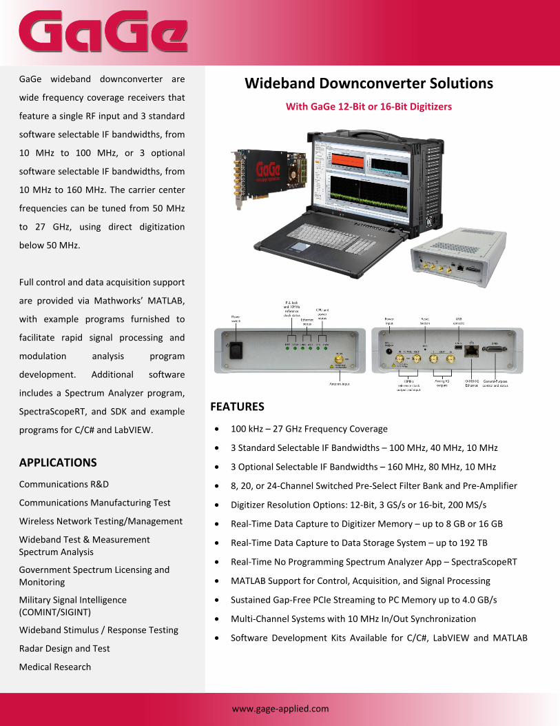
Wideband Downconverter Solutions
With GaGe 12-Bit or 16-Bit Digitizers
FEATURES • 100 kHz – 27 GHz Frequency Coverage
• 3 Standard Selectable IF Bandwidths – 100 MHz, 40 MHz, 10 MHz
• 3 Optional Selectable IF Bandwidths – 160 MHz, 80 MHz, 10 MHz
• 8, 20, or 24-Channel Switched Pre-Select Filter Bank and Pre-Amplifier
• Digitizer Resolution Options: 12-Bit, 3 GS/s or 16-bit, 200 MS/s
• Real-Time Data Capture to Digitizer Memory – up to 8 GB or 16 GB
• Real-Time Data Capture to Data Storage System – up to 192 TB
• Real-Time No Programming Spectrum Analyzer App – SpectraScopeRT
• MATLAB Support for Control, Acquisition, and Signal Processing
• Sustained Gap-Free PCIe Streaming to PC Memory up to 4.0 GB/s
• Multi-Channel Systems with 10 MHz In/Out Synchronization
• Software Development Kits Available for C/C#, LabVIEW and MATLAB
GaGe wideband downconverter are
wide frequency coverage receivers that
feature a single RF input and 3 standard
software selectable IF bandwidths, from
10 MHz to 100 MHz, or 3 optional
software selectable IF bandwidths, from
10 MHz to 160 MHz. The carrier center
frequencies can be tuned from 50 MHz
to 27 GHz, using direct digitization
below 50 MHz.
Full control and data acquisition support
are provided via Mathworks’ MATLAB,
with example programs furnished to
facilitate rapid signal processing and
modulation analysis program
development. Additional software
includes a Spectrum Analyzer program,
SpectraScopeRT, and SDK and example
programs for C/C# and LabVIEW.
APPLICATIONS Communications R&D
Communications Manufacturing Test
Wireless Network Testing/Management
Wideband Test & Measurement Spectrum Analysis
Government Spectrum Licensing and Monitoring
Military Signal Intelligence (COMINT/SIGINT)
Wideband Stimulus / Response Testing
Radar Design and Test
Medical Research

www.gage-applied.com
GaGe Wideband Downconverters – Main Specifications
Downconverter Model
Frequency Coverage
Standard Bandwidth
Optional Bandwidth
Pre-Select Filter Bank
DC8G100 100 kHz – 8 GHz 100 MHz (0 Hz IF), 40 MHz / 10 MHz (35 MHz IF)
160 MHz (0 Hz IF), 80 MHz (55 MHz IF), 10 MHz (35 MHz IF)
8-Channel Switched
DC18G100 100 kHz – 18 GHz 100 MHz (0 Hz IF), 40 MHz / 10 MHz (35 MHz IF)
160 MHz (0 Hz IF), 80 MHz (55 MHz IF), 10 MHz (35 MHz IF)
20-Channel Switched
DC27G100 100 kHz – 27 GHz 100 MHz (0 Hz IF), 40 MHz / 10 MHz (35 MHz IF)
160 MHz (0 Hz IF), 80 MHz (55 MHz IF), 10 MHz (35 MHz IF)
24-Channel Switched
These downconverter models, featuring breakthrough frequency and bandwidth coverage for their size and cost, are available with 3 standard or 3 optional bandwidths, covering three frequency ranges from 100 kHz to 8 GHz, 18 GHz, or 27 GHz. The downconverters feature bandwidths of 100 MHz (standard) or 160 MHz (optional) direct conversion (0 Hz IF) I and Q analog outputs. These wideband versions can be software configured for super heterodyne mode with a bandwidth of either 40 MHz or 10 MHz (standard) on a single IF output centered at 35 MHz IF, or with a bandwidth of either 80 MHz (optional) on a single IF output centered at 55 MHz IF.
These wideband products are engineered for analyzing wideband digital communications - cell phone standards 3G/4G/LTE, WiFi, or general Vector Signal Analysis (VSA) applications involving broadband signals. The Downconverter RF front end is a unique architecture, consisting of both super-heterodyne and direct conversion technologies that are software selectable. The front-end processing blocks utilize up to 24 pre-select filters to mitigate input-related spurs and image responses. The block diagram for the DC27G100 RF front end is shown below.
DC27G100 Block Diagram
www.gage-applied.com
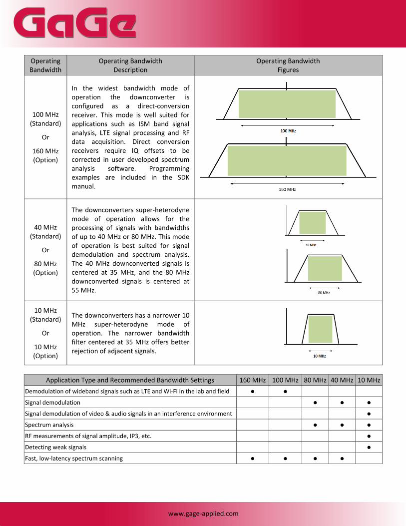
Operating Bandwidth
Operating Bandwidth Description
Operating Bandwidth Figures
100 MHz (Standard)
Or
160 MHz (Option)
In the widest bandwidth mode of operation the downconverter is configured as a direct-conversion receiver. This mode is well suited for applications such as ISM band signal analysis, LTE signal processing and RF data acquisition. Direct conversion receivers require IQ offsets to be corrected in user developed spectrum analysis software. Programming examples are included in the SDK manual.
40 MHz (Standard)
Or
80 MHz (Option)
The downconverters super-heterodyne mode of operation allows for the processing of signals with bandwidths of up to 40 MHz or 80 MHz. This mode of operation is best suited for signal demodulation and spectrum analysis. The 40 MHz downconverted signals is centered at 35 MHz, and the 80 MHz downconverted signals is centered at 55 MHz.
10 MHz (Standard)
Or
10 MHz (Option)
The downconverters has a narrower 10 MHz super-heterodyne mode of operation. The narrower bandwidth filter centered at 35 MHz offers better rejection of adjacent signals.
Application Type and Recommended Bandwidth Settings 160 MHz 100 MHz 80 MHz 40 MHz 10 MHz
Demodulation of wideband signals such as LTE and Wi-Fi in the lab and field Signal demodulation Signal demodulation of video & audio signals in an interference environment Spectrum analysis RF measurements of signal amplitude, IP3, etc. Detecting weak signals Fast, low-latency spectrum scanning
www.gage-applied.com
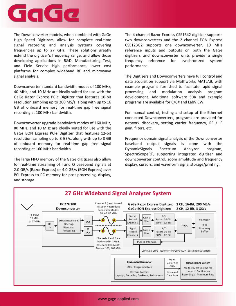
The Downconverter models, when combined with GaGe High Speed Digitizers, allow for complete real-time signal recording and analysis systems covering frequencies up to 27 GHz. These solutions greatly extend the digitizer’s frequency range, and allow those developing applications in R&D, Manufacturing Test, and Field Service high performance, lower cost platforms for complex wideband RF and microwave signal analysis. Downconverter standard bandwidth modes of 100 MHz, 40 MHz, and 10 MHz are ideally suited for use with the GaGe Razor Express PCIe Digitizer that features 16-bit resolution sampling up to 200 MS/s, along with up to 16 GB of onboard memory for real-time gap free signal recording at 100 MHz bandwidth. Downconverter upgrade bandwidth modes of 160 MHz, 80 MHz, and 10 MHz are ideally suited for use with the GaGe EON Express PCIe Digitizer that features 12-bit resolution sampling up to 3 GS/s, along with up to 8 GB of onboard memory for real-time gap free signal recording at 160 MHz bandwidth. The large FIFO memory of the GaGe digitizers also allow for real-time streaming of I and Q baseband signals at 2.0 GB/s (Razor Express) or 4.0 GB/s (EON Express) over PCI Express to PC memory for post processing, display, and storage.
The 4 channel Razor Express CSE1642 digitizer supports two downconverters and the 2 channel EON Express CSE123G2 supports one downconverter. 10 MHz reference inputs and outputs on both the GaGe digitizers and downconverter units provide a single frequency reference for synchronized system performance. The Digitizers and Downconverters have full control and data acquisition support via Mathworks MATLAB, with example programs furnished to facilitate rapid signal processing and modulation analysis program development. Additional software SDK and example programs are available for C/C# and LabVIEW. For manual control, testing and setup of the Ethernet connected Downconverters, programs are provided for network discovery, setting carrier frequency, RF / IF gain, filters, etc. Frequency domain signal analysis of the Downconverter baseband output signals is done with the DynamicSignals Spectrum Analyzer program, SpectraScopeRT, supporting integrated digitizer and downconverter control, zoom amplitude and frequency display, cursors, and waveform signal storage/printing.
27 GHz Wideband Signal Analyzer System

www.gage-applied.com
SpectraScopeRT – Real-Time Spectrum Analyzer Software
The provided real-time Spectrum Analyzer program, SpectraScopeRT, requires no programming and allows for the control of receiver center frequency and bandwidth, plus digitizer selection and functions. This program also features various X,Y display scale viewing options, multiple cursors, averaging, printing, save/recall of setups, and many other useful features for Spectrum Analyzer type functionality. SpectraScopeRT showing:
• IQ Time Domain • I Spectrum • IQ Offset Corrected
100 MHz Power Spectrum
SpectraScopeRT showing:
• A typical WiFi signal using peak hold (red trace) in super-heterodyne mode

www.gage-applied.com
Downconverter Specifications
Tuning and Bandwidth Frequency Range : 100 kHz to 8 GHz, 18 GHz, or 27 GHz
Tuning Resolution with Analog IF Outputs
: 100 kHz
Standard Max. Instantaneous Bandwidth (software selectable)
: 10 MHz, 40 MHz, 100 MHz
Optional Max. Instantaneous Bandwidth (software selectable)
: 10 MHz, 80 MHz, 160 MHz
Spurious Free Dynamic Range (SFDR) @ 100 MHz Bandwidth : ≥ 60 dBc (nominal)
@ 10 / 40 MHz Bandwidth : ≥ 70 dBc (nominal)
Frequency Reference Internal/External : 10 MHz
Internal 10 MHz Oscillator Stability
: ±1 ppm
Phase Coherence : Multi-channel synchronization can be achieved by ordering the external local oscillator inputs option.
Amplitude Accuracy from 100 kHz to 3 GHz, at 25 °C ± 5 °C
: ± 2.00 dB typical
Accuracy from >3 GHz to 8 GHz, at 25 °C ± 5 °C
: ± 2.75 dB typical
Measurement Range : DANL to max. safe input level
Attenuator Range – 8 GHz Model (N/A on 18 or 27 GHz Models)
: 0 or 20 dB
Max. Safe RF Input Level : +10 dBm
RF PLL Phase Noise at 1 GHz (using internal 10 MHz reference)
Frequency Offset 1 kHz 10 KHz 100 kHz 1 MHz RF PLL Phase Noise (dBc/Hz) Typical -90 -105 -115 -143
Displayed Average Noise Level (DANL)
Frequency Without Pre-Amp at 25 °C ± 5 °C 100 MHz -151 dBm/Hz typical 500 MHz -151 dBm/Hz typical
1 GHz -150 dBm/Hz typical 2 GHz -149 dBm/Hz typical 3 GHz -145 dBm/Hz typical 4 GHz -140 dBm/Hz typical 5 GHz -142 dBm/Hz typical 6 GHz -134 dBm/Hz typical 7 GHz -134 dBm/Hz typical 8 GHz -131 dBm/Hz typical
Third Order Intercept (TOI) At 1 GHz : +12 dBm, typical
Gain Control Front-End Attenuator (software selectable)
: 20 dB – 8 GHz model only (N/A for 18 or 27 GHz models)
Pre-Selection Filter Bank 8 GHz Model – DC8G100 : 8-channel switched
18 GHz Model – DC18G100 : 20-channel switched
27 GHz Model – DC27G100 : 24-channel switched
Panel Connectors RF Antenna Input : SMA female, 50 Ω
10 MHz Reference In & Out : SMA female, 50 Ω
Analog I and Q Out : SMA female, 50 Ω
10/100/1000 Ethernet : RJ-45
USB 2.0 Console : Mini-USB
GPIO : 25-pin Male D-Subminiature
Coaxial Power : Type A: 5.5 mm OD, 2.5 mm ID
Physical Power Supply : +12 V DC
Power Consumption : 18 W
Operating Temperature Range : 0°C to +50°C / 32° to 122° F
Storage Temperature Range : -40°C to +85°C / -40° to 185° F
Enclosure Dimensions : 269 (L) x 173 (W) x 55 (H) mm 10.59 (L) x 6.81 (W) x 2.15 (H) inches
Regulatory Compliance RoHS Compliance : RoHS/RoHS 2
Marks : CE European Union
EMC Directive 2014/30/EU : EN 61326-1:2013 Electromagnetic Compatibility
Low Voltage Directive 2006/95/EC
: EN 61010-1:2010 Class 1 Safety

www.gage-applied.com
ORDERING INFORMATION
Hardware Model
Number Frequency Coverage
Standard Bandwidth
Pre-SelectFilter Bank
OrderPart Number
DC8G100 100 kHz – 8 GHz 100 MHz (0 Hz IF), 40 MHz / 10 MHz (35 MHz IF)
8-ChannelSwitched DSD-08G-100
DC18G100 100 kHz – 18 GHz 100 MHz (0 Hz IF), 40 MHz / 10 MHz (35 MHz IF)
20-ChannelSwitched DSD-18G-100
DC27G100 100 kHz – 27 GHz 100 MHz (0 Hz IF), 40 MHz / 10 MHz (35 MHz IF)
24-ChannelSwitched DSD-27G-100
All downconverter models include: power supply, ISM antenna, Ethernet cable, and USB cable
Bandwidth Configuration Upgrade Can be ordered with any of the above downconverter models. Replaces the standard bandwidth for the optional bandwidth configuration as follows:
160 MHz (0 Hz IF), 80 MHz (55 MHz IF), 10 MHz (35 MHz IF) NOTE: This bandwidth configuration upgrade requires the selection of the GaGe 12-bit, 3 GS/s EON Express Digitizer or the Signatec 14-bit, 400 MS/s PX14400D2 Digitizer to be paired with the downconverter unit.
DSD-BWC-160
External Local Oscillator Input Upgrade Radio receiver front-end support for external local oscillator input for direction finding and multi-channel applications. DSD-ELO-100
Accessory Options 19” rackmount shelf that supports two horizontally mounted or six vertically mounted (require separate vertical mounting kit) downconverter units. DSD-RCK-100
Vertical mounting kit for 19” rackmount shelf. Kit contains six vertical mounts including fasteners. Does not include the rackmount shelf. DSD-VMT-100
Wall mount bracket for a single downconverter unit, includes fasteners. DSD-WBK-100
20,000 mAh 12V battery DSD-BAT-100
Software SpectraScopeRT – Real-Time Spectrum Analyzer Software Included
Downconverter Software APIs for C/C++, MATLAB, and LabVIEW Included WARRANTY Standard one year parts and labor. Unless otherwise specified, all dynamic performance specs have been qualified on engineering units. All specifications subject to change without notice. Updated February 11, 2015 GaGe is a product brand of DynamicSignals LLC, an ISO 9001:2008 Certified Company Copyright © 2015 DynamicSignals LLC. All rights reserved.
900 N. State St. Lockport, IL 60441-2200 Toll-Free (USA and Canada): Phone: 1-800-567-4243 Fax: 1-800-780-8411
Direct: Phone: 1-514-633-7447 Fax: 1-514-633-0770
Email: [email protected]
To find your local sales representative or distributor or to learn more about GaGe products visit: www.gage-applied.com


